EP4523829A1 - Horn tip and ultrasonic bonding device - Google Patents
Horn tip and ultrasonic bonding device Download PDFInfo
- Publication number
- EP4523829A1 EP4523829A1 EP23855844.9A EP23855844A EP4523829A1 EP 4523829 A1 EP4523829 A1 EP 4523829A1 EP 23855844 A EP23855844 A EP 23855844A EP 4523829 A1 EP4523829 A1 EP 4523829A1
- Authority
- EP
- European Patent Office
- Prior art keywords
- horn
- tip
- ultrasonic
- bonding
- bottom plate
- Prior art date
- Legal status (The legal status is an assumption and is not a legal conclusion. Google has not performed a legal analysis and makes no representation as to the accuracy of the status listed.)
- Pending
Links
Images


Classifications
-
- B—PERFORMING OPERATIONS; TRANSPORTING
- B23—MACHINE TOOLS; METAL-WORKING NOT OTHERWISE PROVIDED FOR
- B23K—SOLDERING OR UNSOLDERING; WELDING; CLADDING OR PLATING BY SOLDERING OR WELDING; CUTTING BY APPLYING HEAT LOCALLY, e.g. FLAME CUTTING; WORKING BY LASER BEAM
- B23K20/00—Non-electric welding by applying impact or other pressure, with or without the application of heat, e.g. cladding or plating
- B23K20/10—Non-electric welding by applying impact or other pressure, with or without the application of heat, e.g. cladding or plating making use of vibrations, e.g. ultrasonic welding
- B23K20/106—Features related to sonotrodes
Definitions
- the present invention relates to a horn tip used for ultrasonic bonding and an ultrasonic bonding device to which the horn tip is attached when used.
- a tip member in an ultrasonic bonding device of Patent Literature 1, can be freely coupled to and decoupled from an ultrasonic horn for a wide tip.
- a taper part and guide part of the tip member are inserted into a first hole and a second hole of a tip member attachment hole from below the horn and a screw member is inserted into a third hole of the tip member attachment hole from above the horn, and the screw member is fastened from above the horn (refer to Patent Literature 1).
- Patent Literature 1 Japanese Patent Laid-open No. 2022-16741
- the length from the base to a tip part of the tip member is related to the natural frequency of the tip member.
- the tip member and the ultrasonic horn displace in directions opposite to each other, and accordingly, the bottom surface of the tip member lifts from the attachment part during bonding, affecting the bonding accuracy.
- the present invention has been made in view of such circumstances and intended to provide a horn tip that can easily and reliably be attached to an ultrasonic bonding device and ensures stable bonding.
- a first invention is a horn tip used to bond workpieces by ultrasonic bonding, the horn tip comprising a bottom plate part provided with a plurality of through-holes for passing screws and a bonding part vertically protruding from the bottom plate part, in which a ratio h/w of a length h of the bonding part from an upper surface side of the bottom plate part to a thickness w of the bonding part is equal to or smaller than 1.5.
- the horn tip of the present invention is attached to an ultrasonic horn by screws through the plurality of through-holes of the bottom plate part, and thus can reliably be fixed.
- the bonding part vertically protruding from the bottom plate part is used to bond workpieces.
- the ratio h/w of the length h of the bonding part from the upper surface side of the bottom plate part to the thickness w of the bonding part of the horn tip may be equal to or smaller than 1.5.
- the natural frequency of the horn tip and the natural frequency of the ultrasonic horn can be differentiated from each other by setting the thickness w and the length h of the bonding part to this ratio, and thus resonance between a tip member and the ultrasonic horn during workpiece bonding can be avoided. Accordingly, workpiece bonding can be stably performed.
- the bonding part preferably protrudes vertically from one end edge extending in a longitudinal direction of the bottom plate part.
- the horn tip of the first invention preferably comprises a thickened part having a thickness that gradually increases from the bottom plate part toward a base end part continuous with the bonding part.
- the thickened part is provided at a part formed by the bottom plate part and the bonding part of the horn tip, the bonding part does not wobble during bonding of workpieces, which allows stable bonding of the workpieces.
- the bottom plate part is preferably provided with a groove part on a lower surface side that contacts a surface of the ultrasonic horn.
- An ultrasonic bonding device of a second invention comprises: a horn tip comprising a bottom plate part and a bonding part, the bottom plate part being provided with a plurality of through-holes for passing screws, the bonding part vertically protruding from the bottom plate part, a length of the bonding part from an upper surface side of the bottom plate part being equal to or smaller than half of a resonant length; and an ultrasonic horn to which the horn tip can be attached, in which at least one side surface of a tip part of the ultrasonic horn is provided with screw holes corresponding to the through-holes of the horn tip.
- the ultrasonic bonding device of the present invention comprises a tip part corresponding to the same horn tip as the first invention. Screw holes in a number corresponding to the through-holes of the horn tip are provided at the same intervals in the tip part, which allows combined use.
- the tip part preferably has a rectangular column shape.
- the bonding part preferably protrudes vertically from one end edge extending in a longitudinal direction of the bottom plate part, and an end face of the tip part and an end face of the bonding part of the horn tip are preferably flush.
- the horn tip is attached such that the end face of the tip part of the ultrasonic horn is flush with an end part of a bonding surface of the horn tip in a substantially L-shaped column shape. Accordingly, it is possible to easily perform positioning of the horn tip and the workpieces during bonding.
- the screw holes are preferably provided at positions where stress is lower than at a central part of the tip part in an axial direction.
- This stress is force generated due to expansion and contraction of the ultrasonic horn by ultrasonic vibration, and the stress is high and the amount of expansion and contraction is large at the central part of the ultrasonic horn. Accordingly, deformation of the screw holes is large. However, expansion, contraction, and deformation due to ultrasonic vibration are small for screw holes provided at positions where the stress is lower than at the central part. Thus, screws that fix the horn tip do not loosen, which enables reliable fixation of the horn tip.
- a surface of the tip part where the horn tip is attached is preferably provided with a convex part that prevents the horn tip from shifting relative to the tip part.
- the horn tip is prevented from shifting by the convex part provided at the tip part of the ultrasonic horn, and thus it is possible to prevent the position of the horn tip from shifting during bonding of the workpieces, which would otherwise degrade the bonding accuracy.
- a vibration adjustment member can be detachably attached to any of the screw holes, which is provided at a position where the screw hole does not interfere with the horn tip.
- the vibration adjustment member can be attached to any of the screw holes provided in the ultrasonic horn, which is provided at a position where the screw hole does not interfere with the horn tip. It is possible to increase the bonding accuracy of the workpieces by adjusting and equalizing the vibration amplitude at both ends of the ultrasonic horn by using the vibration adjustment member.
- the ultrasonic bonding device 1 is a device that welds bonding target objects (workpieces) such as metal plates by using ultrasonic complex vibration to be described later.
- the ultrasonic bonding device 1 is primarily used for bonding electrodes of a lithium ion battery or a semiconductor element and for bonding metals of the same kind or different kinds.
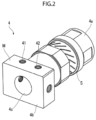
- the ultrasonic bonding device 1 comprises an ultrasonic oscillator (Langevin Type) 2, an ultrasonic booster horn 3, an ultrasonic LT horn 4, a horn tip 6, and an anvil 7.
- an oscillation device 8, a pressurization device 10, a sensor 12, a control device 13, and a display device 14 are parts of the ultrasonic bonding device 1.
- the ultrasonic oscillator 2 When power voltage is applied from a power source (not illustrated) to the oscillation device 8, a voltage signal is transferred to + and - electrodes of the ultrasonic oscillator 2, the ultrasonic oscillator 2 vibrates, and ultrasonic vibration (approximately 20 kHz) is generated.
- the ultrasonic vibration generated in the ultrasonic oscillator 2 is transferred to the cylindrical ultrasonic booster horn 3 attached to one end part of the ultrasonic oscillator 2, and the vibration amplitude is amplified.
- the ultrasonic vibration is further transferred to the cylindrical ultrasonic LT horn 4 attached to one end part of the ultrasonic booster horn 3 (end part on a side that is not the ultrasonic oscillator 2).
- the ultrasonic vibration generated in the ultrasonic oscillator 2 is transferred in the long axis direction of the ultrasonic booster horn 3 and the ultrasonic LT horn 4 (longitudinal vibration of ultrasonic wave), and a vibration component converted from a longitudinal vibration into a transverse vibration is generated by a plurality of diagonal slits S of the ultrasonic LT horn 4. Then, the ultrasonic vibration (complex vibration) is transferred to the horn tip 6 fastened with screws to one end part of the ultrasonic LT horn 4 (end part on a side that is not the ultrasonic booster horn 3).
- the horn tip 6 comprises a tip part that contacts one workpiece W positioned uppermost among a plurality of workpieces W (for example, a plurality of flat plate workpieces stacked in the thickness direction) during bonding of the plurality of workpieces W.
- the control device 13 adjusts the phase and amplitude of longitudinal and torsional vibrations of ultrasonic vibration to generate the complex vibration (for example, elliptical vibration) at the one end part of the ultrasonic LT horn 4, and accordingly, the tip part of the horn tip 6 vibrates in an elliptical trajectory on the surface of the upper workpiece W.
- the horn tip 6 is replaceable in accordance with the kind of the workpiece W, but in this example, a horn tip having a substantially L-shaped plate shape or a substantially L-shaped column shape as illustrated in FIG. 1 and having a substantially quadrilateral bonding surface that contacts the workpiece W is used.
- the complex vibration is vibration that combines, when the tip part of the horn tip 6 presses the upper workpiece W, a vibration component in a first direction perpendicular to the pressing direction and a vibration component in a second direction orthogonal to the first direction.
- the complex vibration is circular vibration when the vibration component in the first direction and the vibration component in the second direction have a phase difference of 90° and an amplitude ratio of 1:1.
- a pressurization block (not illustrated) with high stiffness is in contact with a flange part 3a of the ultrasonic booster horn 3.
- the pressurization device 10 can be controlled by the control device 13 to vertically move the ultrasonic bonding device 1 through the pressurization block operating upward and downward.
- a bonding part 6b of the horn tip 6 contacts the upper workpiece W and static pressure (200 to 800 [N/m2] during bonding) from the bonding part 6b is applied to the workpiece W.
- the bonding strength increases when the static pressure is set to be high, but when the static pressure is set to be too high, the workpieces W are damaged, which leads to fractures and cracks.
- the static pressure is low at start of bonding, the horn tip 6 cannot grip the upper workpiece W and the upper workpiece W slips, which prevents proper bonding.
- Methods of generating the static pressure include a method of pressing the anvil 7 and the lower workpiece W upward from below with an air cylinder, a spring, or the like and a method of pressing the upper workpiece W downward from above by controlling the position and (or) displacement speed of the horn tip 6 with a servomotor, and the latter is employed in the present embodiment.
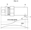
- the sensor (stroke sensor) 12 that detects displacement of the pressurization block is provided, and the control device 13 acquires the pressing amount (indentation amount) of the workpieces W by the horn tip 6.
- the sensor 12 transmits coordinate change of the horn tip 6 in the vertical direction during bonding to the control device 13, and the control device 13 feedback-controls the pressing amount of the workpieces W by the horn tip 6 based on the coordinate change so that the pressing amount is maintained constant.
- an actuator with a fast response speed for a feedback control signal transmitted from the control device 13 is preferably used in the pressurization device 10.
- a target value or temporal change mode of the pressing amount of the workpieces W by the horn tip 6 may be set in advance through the display device 14 by a worker of the ultrasonic bonding device 1. As described above, during workpiece bonding, providing the complex vibration while adjusting the pressing amount and/or the static pressure reliably promotes bonding (solid-phase bonding).
- metal atoms have surfaces covered with grease and/or an oxide layer, which prevent the atoms from approaching each other.
- ultrasonic bonding ultrasonic vibration is applied to metal to generate strong frictional force on the metal surface. Accordingly, an oxide layer and the like on the metal surface are removed, revealing clean and activated metal atoms at the bonding surface.
- attachment surface M a horizontally long surface of the tip part 4b of the ultrasonic LT horn 4. Note that during fabrication with the ultrasonic bonding device 1, the attachment surface M faces vertically downward (in the direction of the anvil 7) (refer to FIG. 1 ).
- the through-holes 61 and 62 are holes formed with no thread grooves and correspond to the interval between the screw holes 41 and 42 of the ultrasonic LT horn 4 (tip part 4b), and the diameters of the holes are slightly larger than those of the screw holes 41 and 42.
- the bonding part 6b has a rectangular plane serving as a contact surface with the upper workpiece W.
- the shape of the contact surface may be elliptical or the like, and the contact surface may be provided with a plurality of protrusions or recessed parts.
- the groove part 63 may be formed to extend in the longitudinal direction of the lower surface side of the bottom plate part 6a or may be constituted by combination of continuous or independent grooves extending in the transverse direction and the longitudinal direction.
- the flat surface of the bottom plate part 6a other than the groove part 63 may be sandblasted to reduce slipping between the bottom plate part 6a and the workpieces W during bonding of the workpieces W.
- the flat surface may be provided with nitride film processing to prevent sticking to the ultrasonic LT horn 4 or rust generation.
- edges of the flat surface may be rounded or chamfered to prevent abrasion of the ultrasonic LT horn 4 and/or the horn tip 6 (bottom plate part 6a).
- the contact surface may be a small rectangular plane with cut-out end parts of a bonding part 16b.
- a thickened part 17c that gradually increases the thickness of the bottom plate part 17a in a positively exponential or quadratic manner may be provided from a middle place of a bottom plate part 17a in the transverse direction toward a base end part continuous with a bonding part 17b.
- through-holes 171 and 172 disposed longitudinally apart from each other in the bottom plate part 17a are formed to penetrate through the bottom plate part 17a in the thickness direction, avoiding the thickened part 17c.
- the thickened part 17c of the horn tip 17 is a part that gradually increases the thickness of the bottom plate part 17a in a positively exponential or quadratic manner from a middle place of the bonding part 17b in the transverse direction toward a base end part continuous with the bottom plate part 17a.
- the thickened part is not limited to the shape illustrated in FIG. 5 .
- the thickened part may be formed to gradually increase the thickness of the bottom plate part 17a linearly or in a negatively exponential manner from a middle place of the bottom plate part 17a in the transverse direction toward a base end part continuous with the bonding part 17b.
- the through-holes 171 and 172 may be formed to at least partially penetrate through the thickened part 17c of the bottom plate part 17a in the thickness direction.
- the thickened part 17c may be formed to gradually increase the thickness of the bottom plate part 17a from a tip place of the bottom plate part 17a toward a tip place of the bonding part 17b.
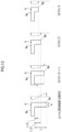
- a horn tip 18 having a substantially T-shaped plate shape or a substantially T-shaped column shape as illustrated in FIG. 6A may be used for the ultrasonic bonding device 1.
- the horn tip 18 comprises a bonding part 18b vertically protruding from substantially the center of a bottom plate part 18a in the transverse direction, and through-holes 181 to 184 are provided on both sides of the bonding part 18b.
- FIG. 6B is a side view of the horn tip 18 when attached to the ultrasonic LT horn 4.
- the horn tip 18 is fixed to the ultrasonic LT horn 4 by screws 30 on both sides of the bonding part 18b.
- a horn tip 19 illustrated in FIG. 7A is constituted by a bottom plate part 19a and a bonding part 19b, the bottom plate part 19a having a substantially quadrilateral plate shape and being provided with three through-holes 191, 192, and 193 disposed horizontally or longitudinally apart from one another, the bonding part 19b extending entirely along one long side edge part of the bottom plate part 19a and protruding in a direction orthogonal to the bottom plate part 19a.
- the horn tip 19 can be attached to an ultrasonic LT horn comprising a tip part provided with three screw holes. According to this aspect, the horn tip 19 is solidly fixed to the ultrasonic LT horn 4, and thus a gap is unlikely to be generated between the horn tip 19 and the ultrasonic LT horn (tip part), which stabilizes fixation to the ultrasonic LT horn 4 as compared to a horn tip with two through-holes.
- the horn tip 19 comprises a thickened part 19c that gradually increases the thickness of the bottom plate part 19a in an exponential or quadratic manner from a middle place of the bottom plate part 19a in the transverse direction toward a base end part continuous with the bonding part 19b.
- FIG. 7B illustrates the lower surface side (side that contacts the ultrasonic LT horn) of the bottom plate part 19a.
- the lower surface side of the bottom plate part 19a is a polished flat surface and provided with a groove part 194 that extends entirely in the longitudinal direction and does not contact the surface of the ultrasonic LT horn at a central part in the transverse direction. Since the contact area is reduced only at the groove part 194, it is possible to reduce generation of frictional heat between the ultrasonic LT horn 4 and the horn tip 19.
- the flat surface may be provided with nitride film processing to prevent bonding between the lower surface side of the bottom plate part 19a and the surface of the ultrasonic LT horn (tip part). Moreover, part of the flat surface may be shaved to the height of the groove part 194, thereby further reducing the contact area.
- a horn tip 20 illustrated in FIG. 8A is constituted by a bottom plate part 20a and a bonding part 20b (deformed T-shaped type), the bottom plate part 20a having a substantially quadrilateral shape and being provided with three through-holes 201, 202, and 203 disposed horizontally apart from each other, the bonding part 20b extending entirely in the longitudinal direction at a central part of the bottom plate part 20a in the transverse direction and protruding in the perpendicularly up-down direction relative to the bottom plate part 20a.
- a thickened part 20c that gradually increases the thickness of the bottom plate part 20a in an exponential or quadratic manner from a middle place of the bottom plate part 20a in the transverse direction toward a base end part continuous with the bonding part 20b is provided on the upper side of the bonding part 20b with respect to the bottom plate part 20a.
- the horn tip 20 is placed at an end part of the ultrasonic LT horn 4 (tip part) and fixed to the ultrasonic LT horn 4 by the screws 30 through the through-holes 201 to 206. Since the horn tip 20 is fixed in two directions, it is possible to reliably prevent slipping of the contact surface between the lower surface side of the bottom plate part 20a and the ultrasonic LT horn 4.
- a horn tip 21 illustrated in FIG. 9 is constituted by a bottom plate part 21a and a bonding part 21b, the bottom plate part 21a being provided with two through-holes 211 and 212 disposed horizontally apart from each other, the bonding part 21b extending entirely in the longitudinal direction at a central part of the bottom plate part 21a in the transverse direction and being placed at an end part of the bottom plate part 21a.
- the bottom plate part 21a comprises ribs 21c that rise toward the bonding part 21b at respective end parts in the transverse direction.
- Each rib 21c is a thickened part having a thickness that gradually and linearly increases from an end edge of the bottom plate part 21a in the longitudinal direction toward a base end part continuous with the bonding part 21b. Since the ribs 21c are provided, it is possible to prevent vibrations of end parts of the bottom plate part 21a in opposite phases and significant vibrations of corners of the end parts in the resonant state of vibrations of the ultrasonic LT horn 4 and a horn tip 9, which would otherwise degrade the bonding accuracy of the workpieces W.
- a plurality of protrusions P are provided at the bonding part 21b.
- the protrusions P are disposed at equal intervals on the bonding part 21b and are structures for reliably bonding the workpieces W by pressing the workpieces W from above.
- the protrusions P may be provided at the above-described horn tips 6 and 16 to 20.
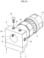
- FIG. 10 is a side view of the above-described horn tip 6 when attached to the ultrasonic LT horn 4.
- the horn tip 6 is preferably attached such that the tip surface of the bonding part 6b and the tip surface of the tip part 4b of the ultrasonic LT horn 4 are flush. Accordingly, it is possible to easily perform position adjustment between the horn tip 6 and the workpieces W during bonding of the workpieces W. Note that the attachment position of the horn tip 6 may be on the rear end side in an axial direction of the ultrasonic LT horn 4, which will be described later in detail.
- the natural frequency (resonance frequency) of the horn tip 6 is adjusted to a value substantially equal to the natural frequency of the ultrasonic LT horn 4.
- the length of the bonding part 6b is adjusted from the upper surface side of the bottom plate part 6a.
- FIG. 11 illustrates the ultrasonic LT horn 4 and the bonding part 6b of the horn tip 6.
- the length h of the bonding part 6b from the upper surface side of the bottom plate part 6a when the natural frequency f1 of the ultrasonic LT horn 4 and the natural frequency f2 of the horn tip 6 are substantially equal to each other is measured, and this length (resonant length) is denoted by L.
- L this length
- FIG. 12 (c) illustrates a case where the length h of the bonding part 6b of the horn tip 6 is further shortened and set to L/2.
- point C is a vibration node (point of zero amplitude), resolving phase inversion between point C of the ultrasonic LT horn 4 and the tip part of the bonding part 6b of the horn tip 6.
- the workpieces W can be bonded by the ultrasonic bonding device 1 with this condition.
- vibrations with amplitudes of different magnitudes occur at point C and the tip part of the bonding part 6b.
- the length h of the bonding part 6b of the horn tip 6 when the thickness w of the bonding part 6b is constant is preferably equal to or shorter than half (1/2) of the resonant length L with which the ultrasonic LT horn 4 and the horn tip 6 resonate, and is more preferably 1/3 to 1/2.
- the ratio h/w of the length h to the thickness w of the bonding part 6b is preferably equal to or smaller than 1.5 (0 ⁇ h/w ⁇ 1.5), and under this condition, it is possible to prevent generation of the gap between the ultrasonic LT horn 4 and the horn tip 6.
- the length h of the bonding part 6b for the same phase can be checked through vibration analysis by gradually shortening the bonding part 6b from the resonant length L, and thus it is advisable to conduct an actual trial. Note that the resonant length L increases as the thickness w of the bonding part 6b increases.
- the horn tip 6 is attached at a position where an end face of the bonding part 6b and an end face of the tip part 4b of the ultrasonic LT horn 4 are flush. Since the vicinity of a central part of the tip part 4b of the ultrasonic LT horn 4 in the axial direction serves as a vibration node, the amount of displacement during vibration is small but stress from vibration (tensile-compressive stress) is large. If the horn tip 6 is attached at a position where stress is large, the screw holes 41 and 42 of the tip part 4b slightly expand when the ultrasonic LT horn 4 is displaced in the extending direction.
- a bonding surface between the cylindrical part 4a and the tip part 4b of the ultrasonic LT horn 4, and the end face of the bonding part 6b are vibration antinodes where the amount of displacement during vibration is large and stress is small.
- the screws 30 that fix the horn tip 6 are preferably provided at positions on the ultrasonic LT horn 4 where stress is relatively small. For example, positions where stress at parts corresponding to the screws 30 is equal to or smaller than 30% of the maximum value are more preferable.
- the screws 30 are attached at positions where stress is relatively small (positions of vibration antinodes), expansion of the screw holes 41 and 42 of the ultrasonic LT horn 4 is prevented so that a screw loosening phenomenon does not occur.
- the horn tip 6 may be provided at a predetermined position on the tip part 4b where stress is relatively small.
- the screw holes are short, which leads to insufficient fixation of the horn tip 6 to the ultrasonic LT horn 4.
- the surface of the tip part 4b where the screw holes are provided is thin, which potentially causes cracks in the tip part 4b.
- a screw hole corresponding to the position of a screw 30b needs to be shortened, and thus fastening force of the screw 30b is insufficient in some cases (refer to FIG. 14B ).
- the tip part 4b of the ultrasonic LT horn 4 may have a form (ultrasonic LT horn 4') with two circular holes 4c1 and 4c2 having diameters smaller than those of the circular hole 4c (refer to FIG. 15A ).
- a screw hole corresponding to the screw 30b is formed between the two circular holes 4c1 and 4c2, and thus the same screw fastening force as with the other screw holes is obtained.
- the horn tip 6 is fixed by three screws 30a to 30c, and thus the horn tip 6 can be reliably attached to the tip part 4b of the ultrasonic LT horn 4'.
- the form of the tip part 4b of the ultrasonic LT horn 4' also affects the vibration amplitude in the longitudinal and torsional directions. Typically, it is known that the vibration amplitude becomes larger as the area of the tip part 4b of the ultrasonic LT horn 4' and its second polar moment of area are reduced.
- the longitudinal amplitude increases as the ratio (A/B) of the cross-sectional area (A) of a part from the rear end (left end part in FIG. 15A ) of the ultrasonic LT horn 4' to its central part to the cross-sectional area (B) of a part from the central part to the rear end (right end part in the drawing) increases.
- the ratio (A/B) increases and longitudinal vibration increases. This leads to amplitude expansion in the torsional direction.
- the second polar moment of area of the tip part 4b of the ultrasonic LT horn 4' is given by (the second polar moment of area of a rectangle part of the tip part 4b) - (the second polar moment of area of the two circular holes of the tip part 4b). Moreover, the second polar moment of area of the circular holes 4c1 and 4c2 increases with separation from the central axis of the tip part 4b (because of longer arms).
- the torsional amplitude increases as the ratio (C/D) of the second polar moment of area (C) of the part from the rear end (left end part in FIG. 15A ) of the ultrasonic LT horn 4' to its central part to the second polar moment of area (D) of the part from the central part to the rear end (right end part in the drawing) increases.
- C/D the ratio of the second polar moment of area (C) of the part from the rear end (left end part in FIG. 15A ) of the ultrasonic LT horn 4' to its central part to the second polar moment of area (D) of the part from the central part to the rear end (right end part in the drawing) increases.
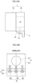
- screw holes 43 and 44 may be provided in a horizontally long surface N (on a side opposite the attachment surface M for the horn tip 6) of the tip part 4b of the ultrasonic LT horn 4 so that a screw-type balancer 35 ("vibration adjustment member" of the present invention) can be detachably attached.
- the balancer 35 is attached to the surface N of the tip part 4b of the ultrasonic LT horn 4 for adjustment to equalize the vibration amplitude between the right and left end parts of the horn tip 6.
- the balancer 35 that serves as a weight is attached on a side where the vibration amplitude is large.
- the balancer 35 may be constituted by a screw and a washer. In this case, the outer diameter of the washer is preferably larger than the diameter of the screw head.
- the balancer 35 can be attached to the screw hole 43 on the left side to equalize the vibration amplitude between the right and left end parts.
- the balancer 35 can be attached to the screw hole 44 on the right side.
- the balancer 35 may be attached to a screw hole 45 or 46 in a side surface of the tip part 4b of the ultrasonic LT horn 4, where the balancer 35 does not interfere with the horn tip 6.
- a plurality of balancers 35 may be attached to the screw holes 43 to 46 for adjustment.
Landscapes
- Engineering & Computer Science (AREA)
- Mechanical Engineering (AREA)
- Apparatuses For Generation Of Mechanical Vibrations (AREA)
- Pressure Welding/Diffusion-Bonding (AREA)
- Lining Or Joining Of Plastics Or The Like (AREA)
Applications Claiming Priority (2)
| Application Number | Priority Date | Filing Date | Title |
|---|---|---|---|
| JP2022131519A JP2024029322A (ja) | 2022-08-22 | 2022-08-22 | ホーンチップ及び超音波接合装置 |
| PCT/JP2023/029882 WO2024043192A1 (ja) | 2022-08-22 | 2023-08-18 | ホーンチップ及び超音波接合装置 |
Publications (1)
| Publication Number | Publication Date |
|---|---|
| EP4523829A1 true EP4523829A1 (en) | 2025-03-19 |
Family
ID=90013308
Family Applications (1)
| Application Number | Title | Priority Date | Filing Date |
|---|---|---|---|
| EP23855844.9A Pending EP4523829A1 (en) | 2022-08-22 | 2023-08-18 | Horn tip and ultrasonic bonding device |
Country Status (7)
| Country | Link |
|---|---|
| US (1) | US20250360576A1 (https=) |
| EP (1) | EP4523829A1 (https=) |
| JP (1) | JP2024029322A (https=) |
| KR (1) | KR20250008943A (https=) |
| CN (1) | CN119365290A (https=) |
| TW (1) | TW202419181A (https=) |
| WO (1) | WO2024043192A1 (https=) |
Family Cites Families (24)
| Publication number | Priority date | Publication date | Assignee | Title |
|---|---|---|---|---|
| DE3508122A1 (de) * | 1985-03-07 | 1986-09-11 | STAPLA Ultraschall-Technik GmbH, 6000 Frankfurt | Vorrichtung zum verbinden elektrischer leiter |
| JPH1064942A (ja) * | 1996-08-21 | 1998-03-06 | Shinkawa Ltd | 超音波ホーンのキャピラリ保持構造 |
| JP3234520B2 (ja) * | 1997-01-07 | 2001-12-04 | 株式会社オートネットワーク技術研究所 | 超音波溶接装置 |
| DE102005022179B4 (de) * | 2004-05-10 | 2008-07-24 | Bandelin Electronic Gmbh & Co Kg | Ultraschallsonotrode |
| US7344620B2 (en) * | 2004-05-10 | 2008-03-18 | Bandelin Electronic Gmbh & Co. Kg | Ultrasonic sonotrode |
| JP5313751B2 (ja) * | 2008-05-07 | 2013-10-09 | パナソニック株式会社 | 電子部品装着装置 |
| JP2010274296A (ja) * | 2009-05-27 | 2010-12-09 | Nissan Motor Co Ltd | 超音波接合装置 |
| JP4798726B2 (ja) * | 2010-02-17 | 2011-10-19 | 精電舎電子工業株式会社 | 布線装置、超音波接合装置、超音波溶着装置 |
| US8082966B2 (en) * | 2010-03-12 | 2011-12-27 | Edison Welding Institute, Inc. | System for enhancing sonotrode performance in ultrasonic additive manufacturing applications |
| JP2013212512A (ja) * | 2012-03-30 | 2013-10-17 | Toshiba Corp | 超音波接合用チップ |
| US20150210003A1 (en) * | 2014-01-28 | 2015-07-30 | Frito-Lay Noth America, Inc. | Transverse Sonotrode Design for Ultrasonic Welding |
| DE102014101856A1 (de) * | 2014-02-13 | 2015-08-13 | Herrmann Ultraschalltechnik Gmbh & Co. Kg | Sonotrode mit Aufdickung |
| JP6559006B2 (ja) * | 2015-08-06 | 2019-08-14 | ブランソン・ウルトラソニックス・コーポレーション | 超音波振動伝達機構部の保持構造 |
| US9346120B1 (en) * | 2015-12-28 | 2016-05-24 | Edison Welding Institute, Inc. | Sonotrode apparatus for use in ultrasonic additive manufacturing |
| WO2020105434A1 (ja) * | 2018-11-20 | 2020-05-28 | 株式会社Link-Us | 超音波接合装置 |
| DE102018132838A1 (de) * | 2018-12-19 | 2020-06-25 | Herrmann Ultraschalltechnik Gmbh & Co. Kg | Ultraschallschweißanlage mit Halterung |
| KR102710862B1 (ko) * | 2019-03-05 | 2024-09-27 | 삼성디스플레이 주식회사 | 표시 장치의 제조 장치 및 표시 장치의 제조 방법 |
| US11426946B2 (en) * | 2020-04-30 | 2022-08-30 | Dukane Ias, Llc | Systems and methods using an ultrasonic transducer and scrubbing horn motion to seal a part |
| US20220388701A1 (en) * | 2020-04-30 | 2022-12-08 | Dukane Ias, Llc | Systems and methods using an ultrasonic transducer and scrubbing horn motion to seal a part |
| US10807314B1 (en) * | 2020-04-30 | 2020-10-20 | Dukane Ias, Llc | Ultrasonic welding systems and methods using dual, synchronized horns on opposite sides of parts to be joined |
| JP7492391B2 (ja) | 2020-07-13 | 2024-05-29 | 日本アビオニクス株式会社 | 超音波接合装置、超音波接合装置のチップ部材及びチップ部材の取付方法 |
| US11311960B2 (en) * | 2020-08-10 | 2022-04-26 | Fabrisonic Llc | High-efficiency welding assembly for use in ultrasonic additive manufacturing |
| US12434322B2 (en) * | 2022-06-21 | 2025-10-07 | Tech-Sonic, Inc. | Ultrasonic welding winder machine for cylindrical batteries |
| US12397462B2 (en) * | 2023-12-07 | 2025-08-26 | Dukane Ias, Llc | High stiffness booster for ultrasonic welding apparatus with a cutting blade integrated into the horn |
-
2022
- 2022-08-22 JP JP2022131519A patent/JP2024029322A/ja active Pending
-
2023
- 2023-08-18 CN CN202380046666.8A patent/CN119365290A/zh active Pending
- 2023-08-18 EP EP23855844.9A patent/EP4523829A1/en active Pending
- 2023-08-18 KR KR1020247041424A patent/KR20250008943A/ko active Pending
- 2023-08-18 US US18/874,889 patent/US20250360576A1/en active Pending
- 2023-08-18 WO PCT/JP2023/029882 patent/WO2024043192A1/ja not_active Ceased
- 2023-08-22 TW TW112131445A patent/TW202419181A/zh unknown
Also Published As
| Publication number | Publication date |
|---|---|
| CN119365290A (zh) | 2025-01-24 |
| US20250360576A1 (en) | 2025-11-27 |
| KR20250008943A (ko) | 2025-01-16 |
| TW202419181A (zh) | 2024-05-16 |
| WO2024043192A1 (ja) | 2024-02-29 |
| JP2024029322A (ja) | 2024-03-06 |
Similar Documents
| Publication | Publication Date | Title |
|---|---|---|
| CN112203794B (zh) | 超声波接合装置 | |
| JP6673961B2 (ja) | 超音波複合振動加工装置 | |
| JP6397807B2 (ja) | 超音波複合振動溶接方法 | |
| KR101589394B1 (ko) | 본딩 장치 | |
| US20030136523A1 (en) | Component bonder and bonding tool | |
| US10291154B2 (en) | Driving device | |
| JP2000052101A (ja) | 楕円振動切削方法及び装置 | |
| EP4523829A1 (en) | Horn tip and ultrasonic bonding device | |
| JP6585217B2 (ja) | 複合曲げ振動検出方法 | |
| JP4088061B2 (ja) | 振動切削方法および振動切削装置 | |
| US8525388B2 (en) | Vibration wave driving apparatus and manufacturing method of vibration body | |
| JP7219495B2 (ja) | 超音波接合装置 | |
| JP3676769B2 (ja) | 加工工具 | |
| JP4213711B2 (ja) | ホーン、ホーンユニット及びそれを用いたボンディング装置 | |
| JP4213713B2 (ja) | ホーンの使用方法及びホーンユニットの使用方法並びにボンディング装置 | |
| JP4213712B2 (ja) | ホーンユニット及びそれを用いたボンディング装置 | |
| JP2017196723A (ja) | 振動加工装置及び振動加工方法 | |
| JP2025159374A (ja) | 超音波接合用チップならびにこれを用いた超音波接合装置および方法 | |
| EP4616966A2 (en) | Ultrasonic composite vibration device and ultrasonic bonding device | |
| JP2025186669A (ja) | 超音波接合用チップおよびこれを用いた超音波接合装置 | |
| JPH02167601A (ja) | たわみ振動子 | |
| JP2012043944A (ja) | 電子部品の実装装置 | |
| JP7169006B2 (ja) | 超音波接合装置 | |
| JP2025134261A (ja) | 超音波接合用チップ構造体、超音波接合装置、超音波接合プログラム | |
| JPH07110141B2 (ja) | 超音波リニアモータ |
Legal Events
| Date | Code | Title | Description |
|---|---|---|---|
| STAA | Information on the status of an ep patent application or granted ep patent |
Free format text: STATUS: THE INTERNATIONAL PUBLICATION HAS BEEN MADE |
|
| PUAI | Public reference made under article 153(3) epc to a published international application that has entered the european phase |
Free format text: ORIGINAL CODE: 0009012 |
|
| STAA | Information on the status of an ep patent application or granted ep patent |
Free format text: STATUS: REQUEST FOR EXAMINATION WAS MADE |
|
| 17P | Request for examination filed |
Effective date: 20241211 |
|
| AK | Designated contracting states |
Kind code of ref document: A1 Designated state(s): AL AT BE BG CH CY CZ DE DK EE ES FI FR GB GR HR HU IE IS IT LI LT LU LV MC ME MK MT NL NO PL PT RO RS SE SI SK SM TR |
|
| DAV | Request for validation of the european patent (deleted) | ||
| DAX | Request for extension of the european patent (deleted) |