EP4497643A1 - Hybridfahrzeug - Google Patents
Hybridfahrzeug Download PDFInfo
- Publication number
- EP4497643A1 EP4497643A1 EP22933270.5A EP22933270A EP4497643A1 EP 4497643 A1 EP4497643 A1 EP 4497643A1 EP 22933270 A EP22933270 A EP 22933270A EP 4497643 A1 EP4497643 A1 EP 4497643A1
- Authority
- EP
- European Patent Office
- Prior art keywords
- engine
- rotational speed
- vehicle
- mode
- driving
- Prior art date
- Legal status (The legal status is an assumption and is not a legal conclusion. Google has not performed a legal analysis and makes no representation as to the accuracy of the status listed.)
- Withdrawn
Links
Images


Classifications
-
- B—PERFORMING OPERATIONS; TRANSPORTING
- B60—VEHICLES IN GENERAL
- B60W—CONJOINT CONTROL OF VEHICLE SUB-UNITS OF DIFFERENT TYPE OR DIFFERENT FUNCTION; CONTROL SYSTEMS SPECIALLY ADAPTED FOR HYBRID VEHICLES; ROAD VEHICLE DRIVE CONTROL SYSTEMS FOR PURPOSES NOT RELATED TO THE CONTROL OF A PARTICULAR SUB-UNIT
- B60W20/00—Control systems specially adapted for hybrid vehicles
- B60W20/10—Controlling the power contribution of each of the prime movers to meet required power demand
- B60W20/15—Control strategies specially adapted for achieving a particular effect
-
- B—PERFORMING OPERATIONS; TRANSPORTING
- B60—VEHICLES IN GENERAL
- B60K—ARRANGEMENT OR MOUNTING OF PROPULSION UNITS OR OF TRANSMISSIONS IN VEHICLES; ARRANGEMENT OR MOUNTING OF PLURAL DIVERSE PRIME-MOVERS IN VEHICLES; AUXILIARY DRIVES FOR VEHICLES; INSTRUMENTATION OR DASHBOARDS FOR VEHICLES; ARRANGEMENTS IN CONNECTION WITH COOLING, AIR INTAKE, GAS EXHAUST OR FUEL SUPPLY OF PROPULSION UNITS IN VEHICLES
- B60K6/00—Arrangement or mounting of plural diverse prime-movers for mutual or common propulsion, e.g. hybrid propulsion systems comprising electric motors and internal combustion engines
- B60K6/20—Arrangement or mounting of plural diverse prime-movers for mutual or common propulsion, e.g. hybrid propulsion systems comprising electric motors and internal combustion engines the prime-movers consisting of electric motors and internal combustion engines, e.g. HEVs
- B60K6/42—Arrangement or mounting of plural diverse prime-movers for mutual or common propulsion, e.g. hybrid propulsion systems comprising electric motors and internal combustion engines the prime-movers consisting of electric motors and internal combustion engines, e.g. HEVs characterised by the architecture of the hybrid electric vehicle
- B60K6/44—Series-parallel type
- B60K6/442—Series-parallel switching type
-
- B—PERFORMING OPERATIONS; TRANSPORTING
- B60—VEHICLES IN GENERAL
- B60W—CONJOINT CONTROL OF VEHICLE SUB-UNITS OF DIFFERENT TYPE OR DIFFERENT FUNCTION; CONTROL SYSTEMS SPECIALLY ADAPTED FOR HYBRID VEHICLES; ROAD VEHICLE DRIVE CONTROL SYSTEMS FOR PURPOSES NOT RELATED TO THE CONTROL OF A PARTICULAR SUB-UNIT
- B60W10/00—Conjoint control of vehicle sub-units of different type or different function
- B60W10/04—Conjoint control of vehicle sub-units of different type or different function including control of propulsion units
- B60W10/06—Conjoint control of vehicle sub-units of different type or different function including control of propulsion units including control of combustion engines
-
- B—PERFORMING OPERATIONS; TRANSPORTING
- B60—VEHICLES IN GENERAL
- B60W—CONJOINT CONTROL OF VEHICLE SUB-UNITS OF DIFFERENT TYPE OR DIFFERENT FUNCTION; CONTROL SYSTEMS SPECIALLY ADAPTED FOR HYBRID VEHICLES; ROAD VEHICLE DRIVE CONTROL SYSTEMS FOR PURPOSES NOT RELATED TO THE CONTROL OF A PARTICULAR SUB-UNIT
- B60W10/00—Conjoint control of vehicle sub-units of different type or different function
- B60W10/04—Conjoint control of vehicle sub-units of different type or different function including control of propulsion units
- B60W10/08—Conjoint control of vehicle sub-units of different type or different function including control of propulsion units including control of electric propulsion units, e.g. motors or generators
-
- B—PERFORMING OPERATIONS; TRANSPORTING
- B60—VEHICLES IN GENERAL
- B60W—CONJOINT CONTROL OF VEHICLE SUB-UNITS OF DIFFERENT TYPE OR DIFFERENT FUNCTION; CONTROL SYSTEMS SPECIALLY ADAPTED FOR HYBRID VEHICLES; ROAD VEHICLE DRIVE CONTROL SYSTEMS FOR PURPOSES NOT RELATED TO THE CONTROL OF A PARTICULAR SUB-UNIT
- B60W10/00—Conjoint control of vehicle sub-units of different type or different function
- B60W10/24—Conjoint control of vehicle sub-units of different type or different function including control of energy storage means
- B60W10/26—Conjoint control of vehicle sub-units of different type or different function including control of energy storage means for electrical energy, e.g. batteries or capacitors
-
- B—PERFORMING OPERATIONS; TRANSPORTING
- B60—VEHICLES IN GENERAL
- B60W—CONJOINT CONTROL OF VEHICLE SUB-UNITS OF DIFFERENT TYPE OR DIFFERENT FUNCTION; CONTROL SYSTEMS SPECIALLY ADAPTED FOR HYBRID VEHICLES; ROAD VEHICLE DRIVE CONTROL SYSTEMS FOR PURPOSES NOT RELATED TO THE CONTROL OF A PARTICULAR SUB-UNIT
- B60W20/00—Control systems specially adapted for hybrid vehicles
- B60W20/10—Controlling the power contribution of each of the prime movers to meet required power demand
- B60W20/15—Control strategies specially adapted for achieving a particular effect
- B60W20/19—Control strategies specially adapted for achieving a particular effect for achieving enhanced acceleration
-
- B—PERFORMING OPERATIONS; TRANSPORTING
- B60—VEHICLES IN GENERAL
- B60W—CONJOINT CONTROL OF VEHICLE SUB-UNITS OF DIFFERENT TYPE OR DIFFERENT FUNCTION; CONTROL SYSTEMS SPECIALLY ADAPTED FOR HYBRID VEHICLES; ROAD VEHICLE DRIVE CONTROL SYSTEMS FOR PURPOSES NOT RELATED TO THE CONTROL OF A PARTICULAR SUB-UNIT
- B60W30/00—Purposes of road vehicle drive control systems not related to the control of a particular sub-unit, e.g. of systems using conjoint control of vehicle sub-units
- B60W30/18—Propelling the vehicle
- B60W30/188—Controlling power parameters of the driveline, e.g. determining the required power
- B60W30/1882—Controlling power parameters of the driveline, e.g. determining the required power characterised by the working point of the engine, e.g. by using engine output chart
-
- B—PERFORMING OPERATIONS; TRANSPORTING
- B60—VEHICLES IN GENERAL
- B60W—CONJOINT CONTROL OF VEHICLE SUB-UNITS OF DIFFERENT TYPE OR DIFFERENT FUNCTION; CONTROL SYSTEMS SPECIALLY ADAPTED FOR HYBRID VEHICLES; ROAD VEHICLE DRIVE CONTROL SYSTEMS FOR PURPOSES NOT RELATED TO THE CONTROL OF A PARTICULAR SUB-UNIT
- B60W50/00—Details of control systems for road vehicle drive control not related to the control of a particular sub-unit, e.g. process diagnostic or vehicle driver interfaces
- B60W50/08—Interaction between the driver and the control system
- B60W50/082—Selecting or switching between different modes of propelling
-
- B—PERFORMING OPERATIONS; TRANSPORTING
- B60—VEHICLES IN GENERAL
- B60W—CONJOINT CONTROL OF VEHICLE SUB-UNITS OF DIFFERENT TYPE OR DIFFERENT FUNCTION; CONTROL SYSTEMS SPECIALLY ADAPTED FOR HYBRID VEHICLES; ROAD VEHICLE DRIVE CONTROL SYSTEMS FOR PURPOSES NOT RELATED TO THE CONTROL OF A PARTICULAR SUB-UNIT
- B60W2520/00—Input parameters relating to overall vehicle dynamics
- B60W2520/10—Longitudinal speed
-
- B—PERFORMING OPERATIONS; TRANSPORTING
- B60—VEHICLES IN GENERAL
- B60W—CONJOINT CONTROL OF VEHICLE SUB-UNITS OF DIFFERENT TYPE OR DIFFERENT FUNCTION; CONTROL SYSTEMS SPECIALLY ADAPTED FOR HYBRID VEHICLES; ROAD VEHICLE DRIVE CONTROL SYSTEMS FOR PURPOSES NOT RELATED TO THE CONTROL OF A PARTICULAR SUB-UNIT
- B60W2540/00—Input parameters relating to occupants
- B60W2540/10—Accelerator pedal position
- B60W2540/106—Rate of change
-
- B—PERFORMING OPERATIONS; TRANSPORTING
- B60—VEHICLES IN GENERAL
- B60W—CONJOINT CONTROL OF VEHICLE SUB-UNITS OF DIFFERENT TYPE OR DIFFERENT FUNCTION; CONTROL SYSTEMS SPECIALLY ADAPTED FOR HYBRID VEHICLES; ROAD VEHICLE DRIVE CONTROL SYSTEMS FOR PURPOSES NOT RELATED TO THE CONTROL OF A PARTICULAR SUB-UNIT
- B60W2540/00—Input parameters relating to occupants
- B60W2540/215—Selection or confirmation of options
-
- B—PERFORMING OPERATIONS; TRANSPORTING
- B60—VEHICLES IN GENERAL
- B60W—CONJOINT CONTROL OF VEHICLE SUB-UNITS OF DIFFERENT TYPE OR DIFFERENT FUNCTION; CONTROL SYSTEMS SPECIALLY ADAPTED FOR HYBRID VEHICLES; ROAD VEHICLE DRIVE CONTROL SYSTEMS FOR PURPOSES NOT RELATED TO THE CONTROL OF A PARTICULAR SUB-UNIT
- B60W2710/00—Output or target parameters relating to a particular sub-units
- B60W2710/06—Combustion engines, Gas turbines
- B60W2710/0644—Engine speed
- B60W2710/065—Idle condition
-
- B—PERFORMING OPERATIONS; TRANSPORTING
- B60—VEHICLES IN GENERAL
- B60W—CONJOINT CONTROL OF VEHICLE SUB-UNITS OF DIFFERENT TYPE OR DIFFERENT FUNCTION; CONTROL SYSTEMS SPECIALLY ADAPTED FOR HYBRID VEHICLES; ROAD VEHICLE DRIVE CONTROL SYSTEMS FOR PURPOSES NOT RELATED TO THE CONTROL OF A PARTICULAR SUB-UNIT
- B60W2710/00—Output or target parameters relating to a particular sub-units
- B60W2710/06—Combustion engines, Gas turbines
- B60W2710/0644—Engine speed
- B60W2710/0661—Speed change rate
-
- B—PERFORMING OPERATIONS; TRANSPORTING
- B60—VEHICLES IN GENERAL
- B60W—CONJOINT CONTROL OF VEHICLE SUB-UNITS OF DIFFERENT TYPE OR DIFFERENT FUNCTION; CONTROL SYSTEMS SPECIALLY ADAPTED FOR HYBRID VEHICLES; ROAD VEHICLE DRIVE CONTROL SYSTEMS FOR PURPOSES NOT RELATED TO THE CONTROL OF A PARTICULAR SUB-UNIT
- B60W2710/00—Output or target parameters relating to a particular sub-units
- B60W2710/08—Electric propulsion units
- B60W2710/081—Speed
- B60W2710/082—Speed change rate
-
- B—PERFORMING OPERATIONS; TRANSPORTING
- B60—VEHICLES IN GENERAL
- B60W—CONJOINT CONTROL OF VEHICLE SUB-UNITS OF DIFFERENT TYPE OR DIFFERENT FUNCTION; CONTROL SYSTEMS SPECIALLY ADAPTED FOR HYBRID VEHICLES; ROAD VEHICLE DRIVE CONTROL SYSTEMS FOR PURPOSES NOT RELATED TO THE CONTROL OF A PARTICULAR SUB-UNIT
- B60W2710/00—Output or target parameters relating to a particular sub-units
- B60W2710/08—Electric propulsion units
- B60W2710/083—Torque
- B60W2710/085—Torque change rate
-
- B—PERFORMING OPERATIONS; TRANSPORTING
- B60—VEHICLES IN GENERAL
- B60W—CONJOINT CONTROL OF VEHICLE SUB-UNITS OF DIFFERENT TYPE OR DIFFERENT FUNCTION; CONTROL SYSTEMS SPECIALLY ADAPTED FOR HYBRID VEHICLES; ROAD VEHICLE DRIVE CONTROL SYSTEMS FOR PURPOSES NOT RELATED TO THE CONTROL OF A PARTICULAR SUB-UNIT
- B60W2710/00—Output or target parameters relating to a particular sub-units
- B60W2710/08—Electric propulsion units
- B60W2710/086—Power
- B60W2710/087—Power change rate
-
- Y—GENERAL TAGGING OF NEW TECHNOLOGICAL DEVELOPMENTS; GENERAL TAGGING OF CROSS-SECTIONAL TECHNOLOGIES SPANNING OVER SEVERAL SECTIONS OF THE IPC; TECHNICAL SUBJECTS COVERED BY FORMER USPC CROSS-REFERENCE ART COLLECTIONS [XRACs] AND DIGESTS
- Y02—TECHNOLOGIES OR APPLICATIONS FOR MITIGATION OR ADAPTATION AGAINST CLIMATE CHANGE
- Y02T—CLIMATE CHANGE MITIGATION TECHNOLOGIES RELATED TO TRANSPORTATION
- Y02T10/00—Road transport of goods or passengers
- Y02T10/60—Other road transportation technologies with climate change mitigation effect
- Y02T10/62—Hybrid vehicles
Definitions
- the present disclosure relates to a hybrid vehicle that performs series driving.
- the hybrid vehicle includes an engine, a motor, and a generator.
- the driving force from the engine causes the generator to generate electric power
- the motor is operated with the generated electric power or battery electric power to generate the driving force for the vehicle.
- the operating state of the engine is controlled, for example, in view of fuel efficiency and quietness. This can lead to effects such as extending the cruising distance of the vehicle and improving the quietness performance (for example, see Patent Document 1).
- Drive modes refer to the sets of driving characteristics and running characteristics of the vehicle (formulated patterns of behaviors of the vehicle in response to operations by the driver). Specific examples of drive modes include a normal mode and a sport mode. The driving characteristics and running characteristics of the vehicle in each mode are controlled to have characteristics appropriate for that mode. For example, the driver requesting output for a given accelerator opening degree is set to a higher value in the sport mode than in the normal mode. This enhances the acceleration response for the same operation of the accelerator because the engine and/or the motor are controlled to produce a greater output, achieving a powerful and responsive driving experience.
- One of the objects of the present disclosure is conceived of in light of the aforementioned problem, and is to provide a hybrid vehicle that can improve the acceleration response in the sport mode during series driving. It is to be noted the object is not limited to the above, and the effects and advantages derived from each configuration described in the 'DESCRIPTION OF EMBODIMENTS' described later, which cannot be achieved by conventional art, are also positioned as other objects of the present disclosure.
- a hybrid vehicle of the disclosure can be embodied in an aspect or application disclosed below and solves at least some of the aforementioned problem.
- the hybrid vehicle of the disclosure is a hybrid vehicle including an engine, a motor, a generator, and a controller that controls an operating state of at least the engine.
- the hybrid vehicle is capable of performing series driving in which driving force from the motor causes the vehicle to drive while driving force from the engine causes the generator to generate electric power.
- the hybrid vehicle has a normal mode in which a driver requesting output is set according to an accelerator opening degree and a sport mode in which the driver requesting output is set to be equal to or higher than the driver requesting output set in the normal mode according to the accelerator opening degree.
- the controller sets a first minimum rotational speed of the engine in the sport mode to be higher than a second minimum rotational speed of the engine in the normal mode during the series driving.
- the engine is controlled such that the first minimum rotational speed of the engine in the sport mode is higher than the second minimum rotational speed of the engine in the normal mode.
- the minimum rotational speed of the engine in the sport mode is controlled to be higher than that in the normal mode.
- the hybrid vehicle of the disclosure may be embodied by the following example.
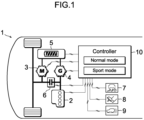
- FIG. 1 is a block diagram illustrating the configuration of a hybrid vehicle 1 as an example.
- This hybrid vehicle 1 (also referred to simply as vehicle 1) is a hybrid vehicle (hybrid electric vehicle, HEV) or a plug-in hybrid vehicle (plug-in hybrid electric vehicle, PHEV), which includes an engine 2 and a motor 3 as drive sources, a generator 4 as an electric power generator, and a battery 5 as an electric power storage apparatus.
- a plug-in hybrid vehicle refers to a hybrid vehicle that allows for external charging to the battery 5 or external power supply from the battery 5.
- the plug-in hybrid vehicle is provided with a charging port (inlet) and/or an electrical wall socket (outlet).
- the charging port (inlet) is for plugging in a charging cable through which electric power is supplied from an external charging facility.
- the electrical wall socket (outlet) is for external power supply.
- the engine 2 is an internal combustion engine, such as a gasoline engine or a diesel engine.
- the generator 4 is connected to the drive shaft of the engine 2.
- the generator 4 is an electric power generator (electric motor and electric power generator) that combines the function of driving the engine 2 with the electric power from the battery 5 and the function of generating electric power using the driving force from the engine 2.
- the electric power generated by the generator 4 is used to drive the motor 3 and charge the battery 5.
- a transmission mechanism which is not illustrated, may be interposed on the power transmission path connecting the engine 2 and the generator 4.
- the motor 3 is an electric motor (electric motor and electric power generator) that combines the function of driving the vehicle 1 using the electric power from the battery 5 or the electric power generated by the generator 4 and the function of charging the battery 5 with the electric power generated by regenerative power generation.
- the battery 5 is a secondary battery, such as a lithium-ion secondary battery or nickel-metal hydride battery.
- the drive shaft of the motor 3 is coupled to the drive wheels of the vehicle 1.
- a transmission mechanism which is not illustrated, may be interposed on the power transmission path connecting the motor 3 and the drive wheels.
- a clutch 6 is interposed on the power transmission path connecting the engine 2 and the motor 3.
- the engine 2 is connected to the drive wheels via the clutch 6, and the motor 3 is positioned on the drive wheel side relative to the clutch 6.
- the generator 4 is connected on the engine 2 side relative to the clutch 6.
- the operating states of the engine 2, the motor 3, the generator 4, the battery 5, and the clutch 6 are controlled by the controller 10.
- the controller 10 is a computer (electronic control unit, ECU) that has at least the function of controlling the operating state of the engine 2.
- the controller 10 has a processor (arithmetic processing unit) and memory (storage device) incorporated therein.
- the contents of the controls to be performed by the controller 10 are stored in the memory, and the contents thereof are read into the processor as appropriate and executed by the processor.
- a drive mode selector 7 is connected to the controller 10 of this example.
- the drive mode selector 7 is a selection device operated by the driver of the vehicle 1 to choose one of the multiple drive modes and is disposed in an area easily accessible from the driver's seat, such as on the instrument panel or around the steering wheel. The information on the type of drive mode selected in response to an operation of the drive mode selector 7 is communicated to the controller 10.
- Drive modes refer to the sets of driving characteristics and running characteristics of the vehicle (formulated patterns of behaviors of the vehicle in response to operations by the driver). Specific examples of drive modes include a normal mode (regular mode), a sport mode (paved road mode), a snow mode (snow road mode), a gravel mode (rough road mode), and an eco mode (energy saving mode, ecological mode).
- the driving characteristics and running characteristics of the vehicle 1 are controlled to have characteristics appropriate for the selected mode.
- the drive mode is basically set to be the preferred mode selected by the driver, but one of the modes may be automatically selected when given driving conditions are satisfied.
- Known characteristics can be adopted as specific driving characteristics and running characteristics for each drive mode.
- the driver requesting output for a given accelerator opening degree is set to a higher value compared to the other modes including the normal mode.
- Such a setting enhances the acceleration response for the same operation of the accelerator, thereby achieving a powerful and responsive driving experience.
- the maximum allowable drive force difference between the left and right wheels is set to a relatively larger value compared to the other modes including the normal mode.
- Such a setting increases the maximum yaw moment that can be generated during cornering, thereby enhancing turning performance.
- the upper limit values of the drive force and braking force are set lower, or the maximum allowable drive force difference between the left and right wheels is set to a relatively smaller value compared to the other modes including the normal mode.
- the ratio of the rotational speed of the drive wheels to the drive source is set to a relatively larger value compared to the other modes including the normal mode. Such a setting increases the torque of the drive wheels, thereby enhancing the rough road performance.
- the rotational speed, torque, output (electric power), and the like are set so that the operating states of the engine 2, the motor 3, and the generator 4 fall within a relatively high-efficiency driving range compared to the other modes including the normal mode.
- Such settings improve the fuel efficiency of the engine 2 and the electricity consumptions of the motor 3 and the generator 4, thereby extending the cruising distance.
- an accelerator opening degree sensor 8 and a vehicle speed sensor 9 are connected to the controller 10 of this example.
- the accelerator opening degree sensor 8 is a sensor that detects parameters (such as accelerator opening degree, accelerator pedal stroke, and throttle opening degree) corresponding to the amount of depression of the accelerator pedal.
- the vehicle speed sensor 9 is a sensor that detects the traveling speed (vehicle speed) of the vehicle 1. The information detected by these sensors 8 and 9 is communicated to the controller 10.
- FIG. 2 is a graph exemplifying the characteristics that define the relationship between the accelerator opening degree [%] detected by the accelerator opening degree sensor 8 and the driver requesting output [kW] set by the controller 10.
- the accelerator opening degree is the amount of depressing of the accelerator pedal (e.g., the accelerator pedal stroke or angle of rotation of the accelerator pedal relative to the fulcrum of the accelerator pedal), expressed in a percentage.
- the driver requesting output is a parameter corresponding to the magnitude of the output that the driver is requesting for driving the vehicle 1 (in other words, horsepower, electric power, or work rate, i.e. energy).
- the output of the drive source for the vehicle 1 is controlled to correspond to the driver requesting output.
- the driver requesting output is set according to the accelerator opening degree.
- the solid line in FIG. 2 indicates the required output characteristic in the sport mode, and the dashed line indicates that characteristic in the normal mode.
- the driver requesting output is zero, as indicated by the dashed line in FIG. 2 . Then, the driver requesting output is set to be roughly proportional to the accelerator opening degree.
- the driver requesting output is set to the same or a higher value compared to the normal mode. In other words, the value of the driver requesting output set in the sport mode is higher than or equal to the value set in the normal mode for the same accelerator opening degree.
- the values of the driver requesting output set in the sport mode and the normal mode only match when the accelerator opening degree is 0 [%] (accelerator is not applied) or 100 [%] (accelerator is fully depressed). For other values of accelerator opening degree than these points, the driver requesting output in the sport mode is always set higher than that in the normal mode.
- the controller 10 performs two types of control on the engine 2 in the sport mode during the series driving to improve the acceleration response of the vehicle 1 for a sudden increase in accelerator opening degree.
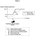
- the first control is a control to set a high engine rotational speed [rpm] (engine revolutions per unit time) for operating engine 2 in preparation for a sudden increase in accelerator opening degree (from when the accelerator is not applied).
- the second control is to make the maximum value of the increase rate, which is the gradient of the change in engine rotational speed over time, larger in the sport mode than in the normal mode, in the situation where the engine rotational speed increases due to an increase in accelerator opening degree.
- the minimum (lowest) rotational speed of the engine in the sport mode is defined as a first minimum rotational speed ⁇ 1
- the minimum (lowest) rotational speed of the engine in the normal mode is defined as a second minimum rotational speed ⁇ 2 .
- the operating state of the engine 2 is controlled so that the first minimum rotational speed ⁇ 1 is higher than the second minimum rotational speed ⁇ 2 .
- the first control is executed when the accelerator pedal is not depressed (before time t 0 ). At this time, the output of the engine 2 (the product of the torque and the rotational speed) is controlled to be almost the same in the sport mode and the normal mode. In other words, in the first control, the first minimum rotational speed ⁇ 1 of the engine 2 is controlled to be higher in the sport mode, instead the torque of the engine 2 is controlled to be lower compared to the normal mode.
- the rotational speed and the torque of the engine 2 can be changed by adjusting the load of the generator 4 on the engine 2 (dynamic power that is to be converted by the generator 4 into electric power).
- the electric power generated by the generator 4 and the output of the motor 3 are also controlled to be the same in the sport mode and the normal mode.
- the output of the motor 3 is controlled to a magnitude, for example, corresponding to the electric power generated by the generator 4, thereby ensuring that battery electric power stored in the battery 5 is not consumed.
- the electric power generated by the generator 4 is controlled to be a certain value according to the output of the engine 2, for example.
- the maximum value of the electric power generated by the generator 4 increases in proportion to the rotational speed of the generator 4 (i.e., the rotational speed of the engine).
- the generator 4 operates with a larger margin for electric power generation compared to the normal mode, making it easier to increase the generated electric power.
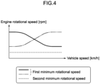
- the value of the first minimum rotational speed ⁇ 1 may be a fixed value set in advance or may be a variable value set according to the driving state of the vehicle 1.
- the first minimum rotational speed ⁇ 1 may be set according to the vehicle speed detected by the vehicle speed sensor 9. For example, as indicated by the solid line in FIG. 4 , the first minimum rotational speed ⁇ 1 may be increased as the vehicle speed reduces.
- Such a setting improves the acceleration response from a stopped state or low-speed driving state, making it easier to achieve a sporty driving experience.
- the first minimum rotational speed ⁇ 1 may be increased as the vehicle speed increases. Such a setting reduces the noise and vibration of the engine 2 in a stopped and low-speed driving state, making it easier to achieve a quieter driving experience.
- the dashed line in FIG. 4 indicates the second minimum rotational speed ⁇ 2 . It is preferable that the first minimum rotational speed ⁇ 1 is always set higher than the second minimum rotational speed ⁇ 2 at any vehicle speed.
- the maximum increase rate of the rotational speed of the engine 2 in the sport mode when in the series driving and when the driver requesting output is not zero is defined as a first increase rate G 1 (also called the first gradient G 1 ).
- the maximum increase rate of the rotational speed of the engine 2 in the normal mode when in the series driving and when the driver requesting output is not zero is defined as a second increase rate G 2 (also called the second gradient G 2 ).
- the operating state of the engine 2 is controlled such that the first increase rate G 1 is greater than the second increase rate G 2 .
- the second control is executed from the time t 0 when the accelerator pedal is fully depressed.
- the increase rate of the rotational speed of the engine 2 is enhanced, for example, by increasing the fuel injection amount or the intake air amount of the engine 2, or by optimizing the ignition timing.
- the upward gradient of the solid line plot becomes steeper compared to the upward gradient of the dashed line plot. In other words, the engine rotational speed reaches the target rotational speed ⁇ TGT in a short time, and the electric power generated by the generator 4 also increases in a short time.
- FIG. 5 is an example flowchart of the first control and the second control described above.
- the control illustrated in this flowchart is repeatedly executed at a given cycle within the controller 10, for example, when the power switch of the vehicle 1 (not illustrated) is turned on and the vehicle 1 is in a drivable state (READY state).
- READY state a drivable state
- Steps A2 to A6 are the flow corresponding to the first control
- Steps A7 to A12 are the flow corresponding to the second control.
- Step A1 it is determined whether or not the vehicle 1 is running in the series driving.
- the series driving is automatically performed, for example, when the state of charge of the battery 5 is equal to or smaller than a given value or when the vehicle 1 is approaching an uphill. Alternatively, it is also performed when the driver wishes to run in the series driving (when a corresponding operational input is made).
- Known conditions can be applied as the specific conditions for performing and starting the series driving. If the condition of Step A1 is satisfied, the control proceeds to Step A2. On the other hand, if the condition of Step A1 is not satisfied, the control in this cycle is terminated.
- Step A2 it is determined whether or not the accelerator opening degree detected by the accelerator opening degree sensor 8 is zero (the accelerator is not applied, OFF state). If this condition is satisfied, the control proceeds to Step A3; if not, the control proceeds to Step A7.
- Step A3 it is determined whether or not the drive mode of the vehicle 1 is the sport mode.
- the control proceeds to Step A4, where the first minimum rotational speed ⁇ 1 of the engine 2 is set according to the vehicle speed detected by the vehicle speed sensor 9.
- the first minimum rotational speed ⁇ 1 has a higher value than the second minimum rotational speed ⁇ 2 , which is set in the normal mode (set in Step A6 described below).
- the operating state of the engine 2 is controlled so that the rotational speed of the engine becomes the first minimum rotational speed ⁇ 1 , and the control in this cycle ends.
- Step A6 the second minimum rotational speed of the engine ⁇ 2 is set.
- the second minimum rotational speed ⁇ 2 has a lower value than the first minimum rotational speed ⁇ 1 , which is set in the sport mode (set in Step A4).
- Step A5 the operating state of the engine 2 is controlled so that the rotational speed of the engine becomes the second minimum rotational speed ⁇ 2 , and the control in this cycle ends.
- Step A7 which is the branch from Step A2 when the accelerator opening degree is not zero (the accelerator is applied)
- the driver requesting output is set according to the accelerator opening degree detected by the accelerator opening degree sensor 8.
- the driver requesting output is set based on a characteristic such as that illustrated in FIG. 2 .
- Step A8 the target rotational speed ⁇ TGT of the engine 2 is set according to the driver requesting output.
- the driver requesting output is relatively large, the difference between the actual engine rotational speed at that time and the target rotational speed ⁇ TGT is large. Accordingly, if the rate to change the engine rotational speed is too low, it would take longer time for the actual engine rotational speed to reach the target rotational speed ⁇ TGT . In contrast, in this example, this rate is changed according to the drive mode.
- Step A9 it is determined whether or not the drive mode of the vehicle 1 is the sport mode.
- the control proceeds to Step A10, where the first increase rate G 1 is set to the maximum increase rate of the engine rotational speed.
- the first increase rate G 1 has a larger value than the second increase rate G 2 which is set in the normal mode (which is set in Step A12 described below).
- Step A11 the operating state of the engine 2 is controlled so that the maximum increase rate of the engine rotational speed becomes the first increase rate G 1 , and the control in this cycle ends.
- Step A9 the control proceeds to Step A12, where the second increase rate G 2 is set to the maximum increase rate of the engine rotational speed.
- the second increase rate G 2 has a smaller value than the first increase rate G 1 which is set in the sport mode (which is set in Step A10).
- Step A11 the operating state of the engine 2 is controlled so that the maximum increase rate of the engine rotational speed becomes the second increase rate G 2 , and the control in this cycle ends.
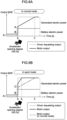
- FIGs. 6A and 6B are graphs indicating the change in motor output in response to an operation of the accelerator.
- FIG. 6A is the graph in the normal mode
- FIG. 6B is the graph in the sport mode.
- the first control is executed before time t 0 .
- the first minimum rotational speed ⁇ 1 of the engine 2 in the sport mode is set higher than the second minimum rotational speed ⁇ 2 of the engine in the normal mode. Accordingly, the engine 2 rotates at the second minimum rotational speed ⁇ 2 before time t 0 in FIG. 6A , and the engine 2 rotates at the first minimum rotational speed ⁇ 1 before time t 0 in FIG. 6B .
- the output of the engine 2 before time t 0 is controlled to be almost the same in the sport mode and the normal mode.
- the electric power generated by the generator 4 and the output of the motor 3 are also controlled to be the same in the sport mode and the normal mode. Therefore, the output value A of the motor 3 before time t 0 in FIG. 6A is the same as the output value A of the motor 3 before time t 0 in FIG. 6B , and the driving state of the vehicle 1 is also the same.
- the second control is executed.
- a large driver requesting output is set according to the accelerator opening degree.
- the motor 3 is driven not only by electric power generated by the generator 4 but also battery electric power stored in the battery 5.
- the motor output in the normal mode at time t 0 is the sum of the output value A corresponding to the generated electric power before time t 0 and the output value B corresponding to the battery electric power.
- the battery electric power corresponds to the output value in the area below the wavy line in FIGs. 6A and 6B
- the generated electric power corresponds to the output value in the area between the wavy line and the solid line above the wavy line in FIGs. 6A and 6B .
- the motor output in the sport mode at time t 0 is the sum of the output value C, which is greater than the output value A, and the output value B.
- the output value C is the output with a magnitude equivalent to the generated electric power increased by the generator 4.
- the first increase rate G 1 of the engine rotational speed in the sport mode is set higher than the second increase rate G 2 of the engine rotational speed in the normal mode.
- the time it takes for the engine rotational speed to increase up to the target speed ⁇ TGT is shorter in the sport mode than in the normal mode.
- the time it takes for the motor output to reach the driver requesting output is also shorter in the sport mode than in the normal mode.
- the motor output reaches the driver requesting output at time t 1 in FIG. 6A
- the motor output reaches the driver requesting output at time t 2 in FIG. 6B , which is earlier than time t 1 .
- the upward gradient of the motor output in the normal mode is gentle, as indicated by the solid line in FIG. 6A [and as indicated by the two-dot chain line in FIG. 6B ].
- the upward gradient of the motor output in the sport mode is steep, as indicated by the solid line in FIG. 6B .
- the vehicle 1 described above includes the drive mode selector 7, the drive mode selector 7 may be omitted and either the normal mode or the sport mode can be automatically selected according to known conditions.
- the controller 10 that executes the first control and the second control on the engine 2 in the sport mode during the series driving is exemplified in the above-described example, the second control can be omitted.
- the first control can improve the acceleration response immediately after the accelerator is applied, and the same effects and advantages as in the above-described example can be obtained.
- the first minimum rotational speed ⁇ 1 may be set to a fixed value, or a parameter other than the vehicle speed may be reflected in the value of the first minimum rotational speed ⁇ 1 .
- the second minimum rotational speed ⁇ 2 which may be set to a fixed value, or the vehicle speed or any other parameter may be reflected in the value of the second minimum rotational speed ⁇ 2 .
- the present disclosure is applicable to the hybrid vehicle manufacturing industry and can be used in the manufacturing industry of controllers for hybrid vehicles
Landscapes
- Engineering & Computer Science (AREA)
- Chemical & Material Sciences (AREA)
- Combustion & Propulsion (AREA)
- Transportation (AREA)
- Mechanical Engineering (AREA)
- Automation & Control Theory (AREA)
- Human Computer Interaction (AREA)
- Hybrid Electric Vehicles (AREA)
- Electric Propulsion And Braking For Vehicles (AREA)
Applications Claiming Priority (1)
| Application Number | Priority Date | Filing Date | Title |
|---|---|---|---|
| PCT/JP2022/013202 WO2023181123A1 (ja) | 2022-03-22 | 2022-03-22 | ハイブリッド車両 |
Publications (2)
| Publication Number | Publication Date |
|---|---|
| EP4497643A1 true EP4497643A1 (de) | 2025-01-29 |
| EP4497643A4 EP4497643A4 (de) | 2025-04-30 |
Family
ID=88100420
Family Applications (1)
| Application Number | Title | Priority Date | Filing Date |
|---|---|---|---|
| EP22933270.5A Withdrawn EP4497643A4 (de) | 2022-03-22 | 2022-03-22 | Hybridfahrzeug |
Country Status (5)
| Country | Link |
|---|---|
| US (1) | US20250187584A1 (de) |
| EP (1) | EP4497643A4 (de) |
| JP (1) | JP7687524B2 (de) |
| CN (1) | CN118742472A (de) |
| WO (1) | WO2023181123A1 (de) |
Families Citing this family (1)
| Publication number | Priority date | Publication date | Assignee | Title |
|---|---|---|---|---|
| US20260048732A1 (en) * | 2024-08-19 | 2026-02-19 | Mclaren Automotive Limited | Rolling start launch control |
Family Cites Families (11)
| Publication number | Priority date | Publication date | Assignee | Title |
|---|---|---|---|---|
| JP3292130B2 (ja) * | 1998-03-06 | 2002-06-17 | 三菱自動車工業株式会社 | シリーズ式ハイブリッド電気自動車 |
| US6554088B2 (en) * | 1998-09-14 | 2003-04-29 | Paice Corporation | Hybrid vehicles |
| JP4197037B2 (ja) * | 2007-03-14 | 2008-12-17 | トヨタ自動車株式会社 | ハイブリッド自動車およびその制御方法 |
| JP2012144138A (ja) | 2011-01-12 | 2012-08-02 | Suzuki Motor Corp | シリーズハイブリッド車両のエンジン制御装置 |
| JP5645124B2 (ja) | 2011-01-21 | 2014-12-24 | スズキ株式会社 | シリーズハイブリッド車両の制御装置 |
| EP2979944B1 (de) * | 2013-03-29 | 2022-02-16 | Hitachi Construction Machinery Co., Ltd. | Motordrehungsteuerungssystem |
| JP6229556B2 (ja) | 2013-04-01 | 2017-11-15 | 株式会社デンソー | 車載回転機の制御装置 |
| JP2019018691A (ja) | 2017-07-14 | 2019-02-07 | 三菱自動車工業株式会社 | ハイブリッド車両の制御装置 |
| JP6620134B2 (ja) * | 2017-10-06 | 2019-12-11 | 本田技研工業株式会社 | ハイブリッド車両 |
| JP7056453B2 (ja) | 2018-08-03 | 2022-04-19 | トヨタ自動車株式会社 | シリーズハイブリッド車両の発電制御装置 |
| JP7283889B2 (ja) * | 2018-11-28 | 2023-05-30 | 株式会社Subaru | 車両制御装置 |
-
2022
- 2022-03-22 CN CN202280092325.XA patent/CN118742472A/zh active Pending
- 2022-03-22 EP EP22933270.5A patent/EP4497643A4/de not_active Withdrawn
- 2022-03-22 WO PCT/JP2022/013202 patent/WO2023181123A1/ja not_active Ceased
- 2022-03-22 JP JP2024508851A patent/JP7687524B2/ja active Active
- 2022-03-22 US US18/846,547 patent/US20250187584A1/en active Pending
Also Published As
| Publication number | Publication date |
|---|---|
| JP7687524B2 (ja) | 2025-06-03 |
| EP4497643A4 (de) | 2025-04-30 |
| JPWO2023181123A1 (de) | 2023-09-28 |
| CN118742472A (zh) | 2024-10-01 |
| US20250187584A1 (en) | 2025-06-12 |
| WO2023181123A1 (ja) | 2023-09-28 |
Similar Documents
| Publication | Publication Date | Title |
|---|---|---|
| US6867509B1 (en) | Control apparatus for transmission-equipped hybrid vehicle, and control method for the same | |
| US10525968B2 (en) | Method for controlling a drive device of a hybrid vehicle and hybrid vehicle | |
| CN101301888B (zh) | 混合动力车辆驱动控制装置和方法 | |
| US8007401B2 (en) | Hybrid vehicle drive control apparatus and method | |
| CN103029701B (zh) | 串联混合动力车辆的驱动控制装置 | |
| CN101765531B (zh) | 车辆的驱动力控制装置 | |
| JPH11324751A (ja) | 駆動力制御装置 | |
| CN101583528A (zh) | 车辆及其控制方法 | |
| CN104080673A (zh) | 混合动力车的变速控制装置和变速控制方法 | |
| WO2012053593A1 (ja) | 発進制御方法、発進制御装置およびハイブリッド自動車、並びにプログラム | |
| JPWO2019116588A1 (ja) | ハイブリッド車両の制御方法及びハイブリッド車両の制御装置 | |
| JP6361634B2 (ja) | ハイブリッド自動車 | |
| WO2013072991A1 (ja) | 車両 | |
| US20020183161A1 (en) | Series hybrid vehicle capable of operating without a battery | |
| CN113548035A (zh) | 一种车辆动力系统控制方法及装置 | |
| JP4240845B2 (ja) | ハイブリッド車 | |
| JP4347071B2 (ja) | 車両およびその制御方法 | |
| JP3601508B2 (ja) | 有段変速機を備えたハイブリッド車両 | |
| EP4497643A1 (de) | Hybridfahrzeug | |
| JP2009215925A (ja) | 車両およびその制御方法 | |
| JP6268993B2 (ja) | 車両の制御装置 | |
| JP2001211506A (ja) | パラレル・ハイブリッド車両の駆動制御装置 | |
| KR20070063336A (ko) | 직렬 및 병렬 하이브리드 자동차에서의 최적 운전점결정방법 | |
| JP3909695B2 (ja) | 車輌の制御装置 | |
| JP5741068B2 (ja) | 電動車両 |
Legal Events
| Date | Code | Title | Description |
|---|---|---|---|
| STAA | Information on the status of an ep patent application or granted ep patent |
Free format text: STATUS: THE INTERNATIONAL PUBLICATION HAS BEEN MADE |
|
| PUAI | Public reference made under article 153(3) epc to a published international application that has entered the european phase |
Free format text: ORIGINAL CODE: 0009012 |
|
| STAA | Information on the status of an ep patent application or granted ep patent |
Free format text: STATUS: REQUEST FOR EXAMINATION WAS MADE |
|
| 17P | Request for examination filed |
Effective date: 20241022 |
|
| AK | Designated contracting states |
Kind code of ref document: A1 Designated state(s): AL AT BE BG CH CY CZ DE DK EE ES FI FR GB GR HR HU IE IS IT LI LT LU LV MC MK MT NL NO PL PT RO RS SE SI SK SM TR |
|
| A4 | Supplementary search report drawn up and despatched |
Effective date: 20250328 |
|
| RIC1 | Information provided on ipc code assigned before grant |
Ipc: B60W 50/08 20200101ALI20250324BHEP Ipc: B60W 30/188 20120101ALI20250324BHEP Ipc: B60W 20/10 20160101ALI20250324BHEP Ipc: B60W 10/26 20060101ALI20250324BHEP Ipc: B60W 10/08 20060101ALI20250324BHEP Ipc: B60K 6/442 20071001ALI20250324BHEP Ipc: B60W 20/19 20160101ALI20250324BHEP Ipc: B60W 10/06 20060101AFI20250324BHEP |
|
| DAV | Request for validation of the european patent (deleted) | ||
| DAX | Request for extension of the european patent (deleted) | ||
| STAA | Information on the status of an ep patent application or granted ep patent |
Free format text: STATUS: THE APPLICATION IS DEEMED TO BE WITHDRAWN |
|
| 18D | Application deemed to be withdrawn |
Effective date: 20251016 |