EP4497635A1 - Sensorkabine, antriebsvorrichtung und installationsverfahren für sensorkabine - Google Patents
Sensorkabine, antriebsvorrichtung und installationsverfahren für sensorkabine Download PDFInfo
- Publication number
- EP4497635A1 EP4497635A1 EP22939006.7A EP22939006A EP4497635A1 EP 4497635 A1 EP4497635 A1 EP 4497635A1 EP 22939006 A EP22939006 A EP 22939006A EP 4497635 A1 EP4497635 A1 EP 4497635A1
- Authority
- EP
- European Patent Office
- Prior art keywords
- compartment
- sensor
- window
- housing
- optical sensor
- Prior art date
- Legal status (The legal status is an assumption and is not a legal conclusion. Google has not performed a legal analysis and makes no representation as to the accuracy of the status listed.)
- Pending
Links
Images





Classifications
-
- B—PERFORMING OPERATIONS; TRANSPORTING
- B60—VEHICLES IN GENERAL
- B60R—VEHICLES, VEHICLE FITTINGS, OR VEHICLE PARTS, NOT OTHERWISE PROVIDED FOR
- B60R11/00—Arrangements for holding or mounting articles, not otherwise provided for
- B60R11/04—Mounting of cameras operative during drive; Arrangement of controls thereof relative to the vehicle
-
- G—PHYSICS
- G01—MEASURING; TESTING
- G01S—RADIO DIRECTION-FINDING; RADIO NAVIGATION; DETERMINING DISTANCE OR VELOCITY BY USE OF RADIO WAVES; LOCATING OR PRESENCE-DETECTING BY USE OF THE REFLECTION OR RERADIATION OF RADIO WAVES; ANALOGOUS ARRANGEMENTS USING OTHER WAVES
- G01S17/00—Systems using the reflection or reradiation of electromagnetic waves other than radio waves, e.g. lidar systems
- G01S17/88—Lidar systems specially adapted for specific applications
- G01S17/93—Lidar systems specially adapted for specific applications for anti-collision purposes
- G01S17/931—Lidar systems specially adapted for specific applications for anti-collision purposes of land vehicles
-
- B—PERFORMING OPERATIONS; TRANSPORTING
- B60—VEHICLES IN GENERAL
- B60R—VEHICLES, VEHICLE FITTINGS, OR VEHICLE PARTS, NOT OTHERWISE PROVIDED FOR
- B60R1/00—Optical viewing arrangements; Real-time viewing arrangements for drivers or passengers using optical image capturing systems, e.g. cameras or video systems specially adapted for use in or on vehicles
- B60R1/20—Real-time viewing arrangements for drivers or passengers using optical image capturing systems, e.g. cameras or video systems specially adapted for use in or on vehicles
- B60R1/22—Real-time viewing arrangements for drivers or passengers using optical image capturing systems, e.g. cameras or video systems specially adapted for use in or on vehicles for viewing an area outside the vehicle, e.g. the exterior of the vehicle
- B60R1/23—Real-time viewing arrangements for drivers or passengers using optical image capturing systems, e.g. cameras or video systems specially adapted for use in or on vehicles for viewing an area outside the vehicle, e.g. the exterior of the vehicle with a predetermined field of view
- B60R1/24—Real-time viewing arrangements for drivers or passengers using optical image capturing systems, e.g. cameras or video systems specially adapted for use in or on vehicles for viewing an area outside the vehicle, e.g. the exterior of the vehicle with a predetermined field of view in front of the vehicle
-
- G—PHYSICS
- G01—MEASURING; TESTING
- G01S—RADIO DIRECTION-FINDING; RADIO NAVIGATION; DETERMINING DISTANCE OR VELOCITY BY USE OF RADIO WAVES; LOCATING OR PRESENCE-DETECTING BY USE OF THE REFLECTION OR RERADIATION OF RADIO WAVES; ANALOGOUS ARRANGEMENTS USING OTHER WAVES
- G01S17/00—Systems using the reflection or reradiation of electromagnetic waves other than radio waves, e.g. lidar systems
- G01S17/86—Combinations of lidar systems with systems other than lidar, radar or sonar, e.g. with direction finders
-
- G—PHYSICS
- G01—MEASURING; TESTING
- G01S—RADIO DIRECTION-FINDING; RADIO NAVIGATION; DETERMINING DISTANCE OR VELOCITY BY USE OF RADIO WAVES; LOCATING OR PRESENCE-DETECTING BY USE OF THE REFLECTION OR RERADIATION OF RADIO WAVES; ANALOGOUS ARRANGEMENTS USING OTHER WAVES
- G01S7/00—Details of systems according to groups G01S13/00, G01S15/00, G01S17/00
- G01S7/48—Details of systems according to groups G01S13/00, G01S15/00, G01S17/00 of systems according to group G01S17/00
- G01S7/481—Constructional features, e.g. arrangements of optical elements
- G01S7/4811—Constructional features, e.g. arrangements of optical elements common to transmitter and receiver
- G01S7/4813—Housing arrangements
-
- G—PHYSICS
- G02—OPTICS
- G02B—OPTICAL ELEMENTS, SYSTEMS OR APPARATUS
- G02B27/00—Optical systems or apparatus not provided for by any of the groups G02B1/00 - G02B26/00, G02B30/00
- G02B27/0006—Optical systems or apparatus not provided for by any of the groups G02B1/00 - G02B26/00, G02B30/00 with means to keep optical surfaces clean, e.g. by preventing or removing dirt, stains, contamination, condensation
-
- B—PERFORMING OPERATIONS; TRANSPORTING
- B60—VEHICLES IN GENERAL
- B60S—SERVICING, CLEANING, REPAIRING, SUPPORTING, LIFTING, OR MANOEUVRING OF VEHICLES, NOT OTHERWISE PROVIDED FOR
- B60S1/00—Cleaning of vehicles
- B60S1/02—Cleaning windscreens, windows or optical devices
- B60S1/56—Cleaning windscreens, windows or optical devices specially adapted for cleaning other parts or devices than front windows or windscreens
-
- B—PERFORMING OPERATIONS; TRANSPORTING
- B60—VEHICLES IN GENERAL
- B60S—SERVICING, CLEANING, REPAIRING, SUPPORTING, LIFTING, OR MANOEUVRING OF VEHICLES, NOT OTHERWISE PROVIDED FOR
- B60S1/00—Cleaning of vehicles
- B60S1/02—Cleaning windscreens, windows or optical devices
- B60S1/56—Cleaning windscreens, windows or optical devices specially adapted for cleaning other parts or devices than front windows or windscreens
- B60S1/566—Cleaning windscreens, windows or optical devices specially adapted for cleaning other parts or devices than front windows or windscreens including wiping devices
-
- B—PERFORMING OPERATIONS; TRANSPORTING
- B60—VEHICLES IN GENERAL
- B60Y—INDEXING SCHEME RELATING TO ASPECTS CROSS-CUTTING VEHICLE TECHNOLOGY
- B60Y2400/00—Special features of vehicle units
- B60Y2400/30—Sensors
- B60Y2400/301—Sensors for position or displacement
- B60Y2400/3015—Optical cameras
-
- G—PHYSICS
- G01—MEASURING; TESTING
- G01S—RADIO DIRECTION-FINDING; RADIO NAVIGATION; DETERMINING DISTANCE OR VELOCITY BY USE OF RADIO WAVES; LOCATING OR PRESENCE-DETECTING BY USE OF THE REFLECTION OR RERADIATION OF RADIO WAVES; ANALOGOUS ARRANGEMENTS USING OTHER WAVES
- G01S7/00—Details of systems according to groups G01S13/00, G01S15/00, G01S17/00
- G01S7/48—Details of systems according to groups G01S13/00, G01S15/00, G01S17/00 of systems according to group G01S17/00
- G01S7/497—Means for monitoring or calibrating
- G01S2007/4975—Means for monitoring or calibrating of sensor obstruction by, e.g. dirt- or ice-coating, e.g. by reflection measurement on front-screen
- G01S2007/4977—Means for monitoring or calibrating of sensor obstruction by, e.g. dirt- or ice-coating, e.g. by reflection measurement on front-screen including means to prevent or remove the obstruction
Definitions
- This application relates to the field of driver assistance system technologies, and in particular, to a sensor compartment that can be used in a driver assistance system, a driving device having a sensor compartment, and a sensor compartment installation method.
- An advanced driver assistance system uses various optical sensors (such as a lidar and a monocular camera or a binocular camera) installed on an automobile to sense a surrounding environment, collect data, identifies, detects, and tracks static and dynamic objects, and performs systematic operation and analysis based on navigation map data at any time in a traveling process of the automobile. In this way, a driver can be aware of a possible danger in advance. This effectively improves automobile driving comfort and safety.
- optical sensors such as a lidar and a monocular camera or a binocular camera
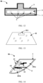
- FIG. 1 shows an installation manner of an optical sensor in an advanced driver assistance system ADAS.
- an inked area is formed on a front windshield 01, and an optical sensor 03 is disposed on a rear side of the inked area.
- an optical sensor 03 is disposed on a rear side of the inked area.
- a position that is in the inked area and that is opposite to the optical sensor 03 is a light-transmitting area 02 that is not inked.
- the optical sensor 03 may sense an environment around the driver's cab through the light-transmitting area 02.
- the light-transmitting area 02 and the other area of the front windshield 01 are of an integrated glass structure.
- the light-transmitting area 02 used as a viewing window of the optical sensor 03 reduces detection performance of the optical sensor 03 (for example, distortion and ghosting occur, and light transmittance is reduced).
- This application provides a sensor compartment, a driving device having the sensor compartment, and a sensor compartment installation method.
- a main objective is to provide a sensor compartment.
- An installation manner of an optical sensor involved in the sensor compartment can improve detection performance of the optical sensor.
- this application provides a sensor compartment.
- the sensor compartment is configured to be installed on a windshield of a driver's cab, for example, a front windshield.
- An embedding groove may be provided on the top of the windshield, and the sensor compartment is configured to be installed in the embedding groove.
- the sensor compartment includes a compartment housing, where the compartment housing is of a sealed structure, the compartment housing has at least one window, and the window is a light-transmitting compartment window.
- the compartment housing is configured to place at least one optical sensor, and light outside the compartment housing can be received by the optical sensor through the compartment window.
- the compartment housing because a light-transmitting compartment window is formed on the compartment housing, light emitted or received by the optical sensor may pass through the compartment window, and the compartment housing is used as a support structure for bearing a field of view window. Further, in some implementations, when a material of the compartment window is selected, glass with high optical performance may be selected as the compartment window, to improve light detection performance of the optical sensor.
- a material of the compartment housing When a material of the compartment housing is selected, more materials can be selected than the material of the compartment window. For example, when glass with an excellent optical property is selected for the compartment window, glass of any light-transmitting material and even plastic can be selected for the compartment housing.
- a shape of the compartment housing is not limited by a field of view of the optical sensor, and the shape of the compartment housing that can be selected is also diversified. In this way, when the compartment housing is embedded in the windshield, that is, when the compartment housing is assembled with the windshield, a requirement on an assembly process of the compartment housing is low.
- the sensor compartment provided in this application is used as a bearing member of the optical sensor. This improves detection performance of the optical sensor, and does not increase assembly process difficulty.
- a viewing window of the optical sensor faces the compartment window.
- the optical sensor may be installed in the compartment housing, so that light is sensed by the optical sensor through the light-transmitting compartment window.
- the viewing window of the optical sensor is embedded in the compartment window.
- the optical sensor when strength of the viewing window material of the optical sensor is high, the optical sensor may be directly embedded in the compartment housing, to expose the viewing window of the optical sensor. In this way, even if the viewing window of the optical sensor is exposed, because the viewing window has high strength, use performance of the optical sensor can also be ensured. In addition, if the viewing window of the optical sensor is directly exposed, detection performance of the optical sensor can be further improved.
- the at least one optical sensor includes a first optical sensor and a second optical sensor, where the first optical sensor includes a visible light camera and/or an infrared camera, and the second optical sensor includes a lidar.
- different types of optical sensors may be all integrated into the compartment housing of the sensor compartment, so that high integration of different optical sensors can be implemented.
- an installation structure configured to install the optical sensor on the top of the driver's cab is omitted. From a perspective of an installation process, a technological process can be simplified. From a perspective of appearance aesthetics, because the optical sensor located on the top of the driver's cab is disposed in the sensor compartment, appearance aesthetics can be improved.
- an isolation plate is disposed in the compartment housing, and the isolation plate divides space in the compartment housing into a first chamber and a second chamber.
- the first optical sensor is disposed in the first chamber, and the second optical sensor is disposed in the second chamber.
- operating environments of the first optical sensor and the second optical sensor may be independent of each other, to avoid performance impact between optical sensors having different operating principles.
- the sensor compartment further includes at least one of a compartment window cleaning apparatus, a compartment window heating apparatus, a compartment housing dehumidification apparatus, and a compartment housing heat dissipation apparatus.
- the optical sensor When the optical sensor operates, there is also a requirement on an operating environment. For example, cleanliness of the compartment window used for light transmission needs to be ensured. In this way, light transmission of the compartment window can be ensured, and light detection performance of the optical sensor can be improved. For another example, fogging and frosting of the compartment window are avoided. Therefore, some environment assistance systems that can process an environment in which the optical sensor is located may be disposed, to improve detection accuracy of the optical sensor.
- the compartment window heating apparatus includes a heating wire.
- the heating wire is arranged along an edge of the compartment window.
- the heating wire can be used to heat the compartment window to prevent the compartment window from fogging and frosting.
- the compartment window heating apparatus includes a heat gun.
- the heat gun is disposed in the compartment housing.
- hot air is generated by the heat gun, and the hot air may flow with airflow to heat the compartment window.
- the compartment window cleaning apparatus includes a wiper and a drive structure.
- the drive structure is connected to the wiper.
- the drive structure can drive the wiper to move between a first position and a second position, when the wiper is in the first position, the wiper is located in the compartment housing, and when the wiper is in the second position, the wiper is located outside the compartment window, to clean the compartment window.
- a surface of the compartment window is cleaned by using the wiper.
- the wiper may be hidden in the compartment housing.
- the drive structure may drive the wiper to move to the outside of the compartment window, to clean a stain on the outer surface of the compartment window by using the wiper.
- a third chamber is formed in the compartment housing.
- the wiper When the wiper is in the first position, the wiper is located in the third chamber, and the third chamber is separated from a chamber in which the optical sensor is disposed in the compartment housing.
- the wiper when the wiper does not operate, the wiper is disposed in the third chamber.
- the third chamber configured to accommodate the wiper is a chamber separated from the chamber accommodating the optical sensor, water carried by the wiper can be prevented from affecting detection performance of the optical sensor.
- the drive structure configured to drive the wiper to move between the first position and the second position may include a telescopic unit, where the telescopic unit may drive the wiper to move in a straight line, to move from the first position to the outside of the third chamber.
- the drive structure may further include a swing sweeper unit. After the wiper moves to the outside of the compartment housing, the swing sweeper unit may drive the wiper to rotate and swing on the outer surface of the compartment window.
- the compartment housing dehumidification apparatus includes a first fan and a water-absorbing structure, where one end of an air duct of the first fan communicates with the inside of the compartment housing, and the other end of the air duct of the first fan communicates with the outside of the compartment housing; and the water-absorbing structure is disposed in the air duct of the first fan.
- the first fan may be used to discharge damp air in the compartment housing to the outside of the compartment housing.
- the water-absorbing structure is disposed in the air duct of the first fan, when the damp air passes through the air duct, moisture in the gas may be absorbed by the water-absorbing structure, to perform dehumidification.
- the water-absorbing structure may be a water-absorbing layer structure obtained by using a water-absorbing material.
- a multi-layer water-absorbing layer structure may be disposed, and the multi-layer water-absorbing layer structure may be arranged in an extension direction of the air duct.
- the compartment housing heat dissipation apparatus includes a second fan and a heat conduction structure, where one end of an air duct of the second fan communicates with the inside of the compartment housing, and the other end of the air duct of the second fan communicates with the outside of the compartment housing; and one part of the heat conduction structure is disposed close to the optical sensor, and another part of the heat conduction structure is close to the air duct of the fan.
- the second fan herein may discharge hot air in the compartment housing to the outside of the compartment housing, heat diffused by the optical sensor is conducted to the air duct of the fan by using the heat conduction structure, and heat dissipation is performed on the optical sensor by using a flow channel of the airflow in the air duct. This improves use performance of the optical sensor.
- the first fan and the second fan may be one fan, or may be two fans independent of each other.
- the compartment housing is made of an opaque material.
- the compartment housing may be made of plastic, or another opaque material.
- the position of the formed sensor compartment may be similar to the existing inked area, and may perform sun-shading, heat insulation, and beautification, to prevent some structural members or electronic components in the sensor compartment from being seen from the outside of the driver's cab.
- a surface that is of the compartment housing and that is configured to be opposite to the top of the driver's cab protrudes toward the outside of the compartment housing.
- a surface that is of the compartment housing and that faces the outside of the driver's cab is a curved surface protruding toward the outside of the compartment housing.
- space in the compartment housing for accommodating the optical sensor can also be expanded.
- this application further provides a driving device, including a windshield.
- the driving device further includes the sensor compartment in any one of implementations of the first aspect, and at least one optical sensor.
- the compartment housing of the sensor compartment is embedded in the windshield, and the at least one optical sensor is placed in the compartment housing.
- the driving device provided in this application includes the sensor compartment in any one of implementations of the first aspect, and the compartment window is used as field of view glass of the optical sensor.
- the compartment window is used as field of view glass of the optical sensor.
- a compartment window with excellent optical performance may be selected as the field of view glass, to improve detection performance of the optical sensor.
- the compartment housing is different from the compartment window in that diversified materials may be selected, a shape is not affected by the detection performance of the optical sensor, and different shapes may be selected. Therefore, when the compartment housing is assembled with the windshield, assembly process difficulty is not increased.
- the windshield herein may be a front windshield or a rear windshield.
- an embedding groove is provided at a position that is on the windshield and that is close to the top of a driver's cab, and the compartment housing is installed in the embedding groove and is connected to the windshield in a sealed manner.
- the embedding groove may be provided at a top position of the windshield, to embed the sensor compartment in the embedding groove.
- the driving device further includes a rear view mirror disposed in the driver's cab, and the rear view mirror is installed on a part that is of the compartment housing and that is located in the driver's cab.
- rear view mirror can be directly installed on the compartment housing.
- a concave chamber may be disposed on the part that is of the compartment housing and that is located in the driver's cab, the rear view mirror is installed in the concave chamber; or the rear view mirror may be installed on the compartment housing by using a bracket.
- a sensor compartment includes a compartment housing, the compartment housing is sealed, at least one window is provided on the compartment housing, the window is a light-transmitting compartment window, the compartment housing is configured to place at least one optical sensor, and light outside the compartment housing can be received by the optical sensor through the compartment window.
- the installation method includes:
- the compartment housing is not used as the field of view glass of the optical sensor, but as a bearing support body of the optical sensor.
- a material and a shape of the compartment housing compared with selection of a material and a shape of the field of view glass, there are no many limitations.
- a requirement on an assembly process between the compartment housing and the windshield is low.
- a compartment window with excellent optical performance may be selected as the field of view glass, to improve detection performance of the optical sensor.
- the method before the installing the compartment housing of the sensor compartment in an embedding groove on a windshield, the method further includes cleaning a position that is on the embedding groove and that is in contact with the compartment housing.
- FIG. 2 is a diagram of a structure viewed from the front of a driving device 100.
- a front windshield 01 is installed on a front side of a driver's cab 04
- an inked area 05 is formed on the top of the front windshield 01
- the inked area 05 may perform sun-shading and heat insulation.
- a rear view mirror is usually installed on an inner side of the front windshield 01 (that is, located in the driver's cab)
- the inked area 05 may also cover the rear view mirror, to improve appearance aesthetics of the driver's cab.
- the inked area 05 also has another function.
- A-pillar, B-pillar, and C-pillar of an automobile As shown in FIG. 3 , in the driving device 100, for example, there are three pillars on two sides of glass of a front door and a rear door of the automobile, and the pillars are sequentially a front pillar (the A-pillar), a middle pillar (the B-pillar), and a rear pillar (the C-pillar) from front to back.
- the A-pillar, the B-pillar, and the C-pillar mainly play a supporting role.
- the front windshield 01 is installed on the A-pillar, and a rear windshield is installed on the C-pillar.
- Viewing window of an optical sensor A lens that is of the optical sensor and is closest to an object side and that is exposed outside the entire optical sensor and is configured to sense light is the viewing window of the optical sensor.
- the driving device may be an automobile shown in FIG. 4 , and the automobile may be a manned automobile, or may be an unmanned automobile.
- the driving device may be a train, an automobile, or the like.
- the accompanying drawings used below are described by using an automobile as an example.
- an advanced driver assistance system (advanced driving assistance system, ADAS) is disposed, that is, driving safety is improved by using the ADAS.
- the ADAS mainly includes various optical sensors, for example, a visible light camera, an infrared camera, and a lidar.
- the optical sensors sense an environment around the driving device, to predict the environment around the driving device. Further, there are high requirements on use performance of these optical sensors, for example, eliminating distortion, eliminating ghosting, and improving light transmittance.
- optical sensors are usually disposed close to a windshield, for example, disposed close to the front windshield 01. Therefore, during specific installation of the optical sensor, limitations on some installation processes and optical properties of the front windshield affect use performance of the optical sensor. For example, light transmittance of the front windshield becomes a constraint factor for improving detection performance of the optical sensor.
- This application provides a sensor compartment that can be used in a driving device.
- the sensor compartment changes an installation manner of an optical sensor in the driving device.
- Use of the installation manner of the optical sensor provided in this application can improve detection performance of the optical sensor, and does not increase assembly process difficulty on the windshield.
- FIG. 4 is a diagram of a structure of a driving device 100 including a sensor compartment 06 in this application.
- the diagram of the structure is a front view of the driving device 100.
- FIG. 5 is a diagram of a part of the structure of the driving device 100 including the sensor compartment 06 in this application.
- the diagram of the structure is a side view of the driving device 100.
- FIG. 6a and FIG. 6b are diagrams of a structure of a front windshield 01 in FIG. 4 and FIG. 5 .
- the sensor compartment 06 is installed on the front windshield 01 .
- the sensor compartment 06 in this application may alternatively be installed on a rear windshield.
- an embedding groove 011 may be provided at a position on the top of the front windshield 01, and the sensor compartment 06 shown in FIG. 4 and FIG. 5 is installed in the embedding groove 011.
- the top of the front windshield 01 means a position that is on the front windshield 01 and that is close to the top of a driver's cab.
- the embedding groove 011 penetrates to the top edge of the front windshield 01.
- the embedding groove 011 does not penetrate to the top edge of the front windshield 01, but has a spacing from the top edge.
- the spacing may range from 2 cm to 10 cm, that is, a hole is formed on the front windshield 01, and the hole is configured to install the sensor compartment 06.
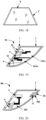
- FIG. 7 shows an implementable structure of the sensor compartment 06 according to this application, and FIG. 7 shows an optical sensor 4.
- the sensor compartment 06 includes a compartment housing 1, and the compartment housing 1 may be embedded in the embedding groove 011 shown in FIG. 6a and FIG. 6b .
- a sealing structure may be formed at a contact position between the compartment housing 1 and the front windshield 01.
- a sealing adhesive layer 3 may be formed along the outer edge of the compartment housing 1, that is, the compartment housing 1 is connected to the front windshield 01 by using the sealing adhesive layer 3 in a sealed manner.
- no sealing adhesive layer 3 is disposed at a position that is on the compartment housing 1 and that is close to the vehicle top of the driver's cab.
- the sealing adhesive layer 3 may alternatively be disposed at the position that is on the compartment housing 1 and that is close to the vehicle top of the driver's cab, to further improve sealing of the entire driver's cab.
- At least one window is provided on a surface that is of the compartment housing 1 and that faces the outside of the driver's cab, and the window is a light-transmitting compartment window 2.
- FIG. 7 shows an example in which there is a light-transmitting compartment window 2 on the compartment housing 1.
- At least one optical sensor 4 may be disposed in the compartment housing 1 of the sensor compartment 06. As shown in FIG. 7 , four optical sensors 4 are included.
- the compartment window 2 is used as a field of view window of the optical sensor 4, and light emitted or received by the optical sensor 4 may pass through the compartment window 2, to detect a situation outside the driver's cab.
- a manner of disposing the optical sensor 4 in the compartment housing 1 may include a plurality of cases. The following provides two installation manners with reference to the accompanying drawings.
- FIG. 8 shows an arrangement manner of the optical sensor 4. Specifically, a receptacle 101 is formed in the compartment housing 1, the optical sensor 4 is disposed in the receptacle 101, and a viewing window of the optical sensor 4 faces the compartment window 2. In this way, light outside the compartment housing 1 may be received by the optical sensor 4 located in the compartment housing 1 through the light-transmitting compartment window 2, or light emitted by the optical sensor 4 may pass through the compartment window 2.
- Glass with low roughness and high light transmission may be selected for the compartment window 2 in FIG. 8 , or an antireflection film may be formed on the compartment window 2, to avoid ghosting. This further improves a signal-to-noise ratio, and improves detection performance of the optical sensor 4.
- FIG. 9 shows another arrangement manner of the optical sensor 4.
- the viewing window of the optical sensor 4 is directly embedded in the compartment window 2, that is, the viewing window of the optical sensor 4 is used as the compartment window and is directly exposed outside the driver's cab.
- the installation manner of the optical sensor 4 shown in FIG. 9 can be used.
- the optical sensor 4 When the optical sensor 4 is installed in the manner shown in FIG. 9 , because the viewing window of the optical sensor 4 is directly exposed outside the driving device, the optical sensor 4 can directly sense external light, to fully reflect detection performance of the optical sensor.
- the compartment window 2 disposed on the compartment housing 1 is used as field of view glass of the optical sensor 4.
- the field of view glass with an excellent optical property may be selected as the compartment window, to improve detection performance of the optical sensor 4.
- the compartment housing 1 configured to bear the optical sensor 4 needs to be assembled with the front windshield 01. That is, the compartment housing 1 serves as a support structure of the optical sensor 4 and a structure connected to the front windshield 01, and is not used as a field of view structure of the optical sensor 4. In this way, the compartment housing 1 is different from the compartment window 2 used as the field of view glass in that diversified materials may be selected. For example, light-transmitting glass or opaque plastic may be selected, and for the light-transmitting glass or the opaque plastic, composition may not be limited. In this way, compared with assembling the front windshield 01 and the compartment window that has a material limitation, assembling the front windshield 01 and the compartment housing 1 has low process difficulty. This does not increase process difficulty in assembling the sensor compartment 06 on the windshield.
- the compartment housing 1 and the front windshield 01 are assembled, and diversified materials may be selected for the compartment housing 1.
- plastic obtained by using an injection molding process may be used.
- the injection molding process it can be easily implemented that a curvature radius of the compartment housing 1 is close to a curvature radius of the front windshield 01, so that for a manufacturing process, process difficulty can be reduced, and production costs can be reduced.
- the sensor compartment 06 provided in this application can improve detection performance of the optical sensor 4, and does not increase assembly process difficulty.
- the compartment housing 1 may be made of an opaque material.
- the opaque compartment housing 1 may perform sun-shading and heat insulation, to avoid a high temperature in the compartment housing 1. This avoids that the high temperature affects the detection performance of the optical sensor 4.
- a shape of the compartment window 2 may be designed based on a field of view of the optical sensor 4.
- FIG. 10 shows two structures of the compartment window 2 in different shapes. One is a polygonal structure, and the other is a circular structure.
- FIG. 10 is merely an example for description.
- a structure of the compartment window 2 may include the structure shown in FIG. 10 , but is not limited thereto.
- a window may be provided on the compartment housing 1 based on an appearance structure of the viewing window of the optical sensor, to seal and assemble the viewing window of the optical sensor 4 to the window.
- compartment housing 1 is not limited in this application either.
- the following provides examples of several compartment housings 1 in different shapes.
- FIG. 7 shows that an appearance of the compartment housing 1 is of a polygonal structure.
- the embedding groove 011 provided on the front windshield 01 is a polygonal groove shown in FIG. 6a and FIG. 6b .
- FIG. 10 shows that an appearance of the compartment housing 1 is of a sector structure.
- the embedding groove 011 provided on the front windshield 01 is a sector groove shown in FIG. 11 .
- FIG. 12 shows that an appearance of the compartment housing 1 is of a T-shaped structure.
- the embedding groove 011 provided on the front windshield 01 is a T-shaped groove shown in FIG. 13 .
- a visible light camera or an infrared camera may be included.
- a plurality of cameras may be included.
- a visible light camera and an infrared camera may be included, a visible light camera, an infrared camera, and a lidar may be included, or an infrared camera and a lidar may be included.
- another type of imaging sensor may also be included.
- the compartment housing 1 may be used as a support structure, and a plurality of optical sensors implementing different functions are all integrated into the compartment housing 1. This, compared with disposing some optical sensors on the vehicle top of the driver's cab and disposing some optical sensors in the driver's cab, can improve integration of the optical sensors, so that the optical sensors are modularized and integrated together.
- optical sensors 4 there may be a plurality of optical sensors 4 in this application.
- a structure shown in FIG. 14 shows three optical sensors, including two first optical sensors 41 and one second optical sensor 42.
- the first optical sensor 41 may be an imaging sensor, for example, at least one of a visible light camera and an infrared camera, and the second optical sensor 42 may be a lidar.
- an isolation plate 5 is disposed in a receptacle of the compartment housing 1, to divide the receptacle into a first receptacle 101a and a second receptacle 101b.
- the first optical sensor 41 is disposed in the first receptacle 101a
- the second optical sensor 42 is disposed in the second receptacle 101b.
- the receptacle in the compartment housing 1 may be divided into a plurality of mutually independent accommodation areas, so that the optical sensors having different operating principles are disposed in different areas. This improves use performance of any optical sensor.
- the optical sensor 4 may be installed in the compartment housing 1 by using a sensor bracket 12.
- FIG. 14 shows an implementable structure of the sensor bracket 12
- FIG. 8 and FIG. 9 each show another implementable structure of the sensor bracket 12.
- a structure of the sensor bracket 12 and a structure connecting the sensor bracket 12 to the compartment housing 1 are not specially limited in this application.
- the sensor compartment 06 provided in this application further includes an environment assistance system.
- the environment assistance system may provide a better operating environment for the optical sensor 4.
- the environment assistance system may clean the compartment window 2 to improve light transmittance.
- the environment assistance system may heat the compartment window 2.
- the environment assistance system may perform heating in the compartment housing 1.
- the environment assistance system may perform dehumidification.
- the environment assistance system is configured to implement at least one of cleaning of the compartment window, heating of the compartment window, dehumidification in the compartment housing, and heat dissipation in the compartment housing, to provide a better operating environment for the optical sensor 4, and further improve detection performance of the optical sensor 4.
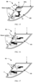
- FIG. 15 is a diagram of a structure of a sensor compartment 06 including a compartment window cleaning apparatus.
- the compartment window cleaning apparatus includes a wiper 6 that can clean an outer surface (a surface facing the outside of the driver's cab) of the compartment window 2, and an independent third receptacle 101c that can accommodate the wiper 6 is formed in the receptacle 101 of the compartment housing 1.
- the wiper 6 does not perform a cleaning operation, the wiper 6 is hidden in the third receptacle 101c.
- the wiper 6 may extend, driven by a drive structure, to the outer surface of the compartment window 2. That is, driven by the drive structure, the wiper 6 may move from a first position (located in the third receptacle 101c) to a second position (located outside the compartment window 2).
- the drive structure that drives the wiper 6 to move from the third receptacle 101c to the outer surface of the compartment window 2 may include: a telescopic unit that drives the wiper 6 to move in a P direction in FIG. 15 ; and a swing sweeper unit that drives the wiper 6 to swing on the outer surface of the compartment window 2.
- the wiper 6 when the wiper 6 specifically operates, the wiper 6 is first driven by the telescopic unit to move in a straight line from the inside of third receptacle 101c to the outside of the third receptacle 101c in the P direction, and is driven by the swing sweeper unit to rotate on the outer surface of the compartment window 2, to clean the outer surface of the compartment window 2.
- the telescopic unit may be a telescopic rod driven by a motor, a telescopic rod driven by hydraulic pressure, or a telescopic structure of another structural type.
- the swing sweeper unit may include a rotating motor, and an output shaft of the rotating motor may drive the wiper 6 to rotate on the outer surface of the compartment window 2.
- an output shaft of the rotating motor may drive the wiper 6 to rotate on the outer surface of the compartment window 2.
- another structure that drives the wiper 6 to rotate may alternatively be used.
- the third receptacle 101c for accommodating the wiper 6 and the chamber for accommodating the optical sensor 4 are separated, when the wiper 6 located in the third receptacle 101c carries water, the water does not enter space in which the optical sensor 4 is located and does not affect performance of the optical sensor 4.
- FIG. 16 is a diagram of a structure of another sensor compartment 06 including a compartment window cleaning apparatus.
- the compartment window cleaning apparatus includes a nozzle 7 that can clean the outer surface of the compartment window 2, and the nozzle 7 may be installed at a position that is on the compartment housing 1 and that is close to the vehicle top of the driver's cab.
- a cleaning liquid sprayed by the nozzle 7 may be sprayed on the outer surface of the compartment window 2, or sprayed on the entire surface that is of the compartment housing 1 and the compartment window 2 and that faces the outside of the driver's cab.
- the cleaning liquid used for the nozzle 7 in FIG. 16 can be shared with a cleaning liquid of the existing wiper, that is, an output pipe of the cleaning liquid of the existing wiper can communicate with the nozzle 7.
- How the nozzle 7 communicates with the output pipe of the cleaning liquid of the wiper is not specially limited in this application.
- the wiper 6 shown in FIG. 15 may be combined and assembled with the nozzle 7 shown in FIG. 16 to clean the outer surface of the compartment window.
- FIG. 17 is a diagram of a structure of a sensor compartment 06 including a compartment window heating apparatus.
- the compartment window heating apparatus includes a heating wire 8 that can heat the compartment window 2.
- FIG. 18 is a simple diagram of a structure of the compartment window 2 including the heating wire 8. Refer to FIG. 17 and FIG. 18 .
- the heating wire 8 may be arranged along an edge of the compartment window 2. In this way, frost, fog, and the like deposited on the surface of the compartment window 2 may be heated by using heat dissipated by the heating wire 8, so that the frost melts and evaporates. This ensures light transmittance of the compartment window 2.
- the heating wire 8 in this application is disposed along the edge of the compartment window 2, that is, at a position that is on the compartment window 2 and that is close to the compartment housing 1. In this way, the field of view of the optical sensor 4 is not interfered.
- the heating wire 8 may be implemented by an electric heating wire.
- the electric heating wire is a conductive metal wire with high impedance. After being energized, the electric heating wire generates heat, and the heat is transferred to the entire compartment window 2 through heat conduction, so that the compartment window 2 is warmed up, and ice or fog on the compartment window 2 is eliminated.
- FIG. 19 is a diagram of a structure of another sensor compartment 06 including a compartment window heating apparatus.
- the compartment window heating apparatus includes a heat gun 9 that can heat the compartment window 2, and the heat gun 9 is disposed in the receptacle in the compartment housing 1.
- the receptacle in the compartment housing 1 is divided into a first receptacle 101a and a second receptacle 101b that are independent of each other, and the heat gun 9 may be disposed in each of the first receptacle 101a and the second receptacle 101b.
- the heat gun 9 When the heating apparatus shown in FIG. 19 operates, the heat gun 9 generates hot air.
- the hot air flows to the compartment window 2 with the flowing airflow.
- frost on the outer surface of the compartment window 2 is removed in a heat convection manner, to create a better operating environment for the optical sensor 4.
- FIG. 20 is a diagram of a structure of a sensor compartment 06 including a compartment housing dehumidification apparatus.
- the compartment housing dehumidification apparatus shown in FIG. 20 includes a first fan 10, one end (an air inlet) of an air duct 10a of the first fan 10 communicates with the chamber accommodating the optical sensor 4 in the compartment housing 1, and the other end (an air outlet) of the air duct 10a of the first fan 10 communicates with the outside of the compartment housing 1.
- the compartment housing dehumidification apparatus further includes an absorption structure 11, and the water-absorbing structure 11 is disposed in the air duct 10a.
- the first fan 10 can discharge air in the compartment housing 1 to the outside of the compartment housing 1, and when the air passes through the air duct 10a, moisture stored in the water-absorbing structure 11 can evaporate with the wind to the outside of the compartment housing 1, to perform dehumidification on the compartment housing.
- the absorption structure 11 may be an absorption layer structure made of a water-absorbing material.
- the water-absorbing material may be selected from starch-grafted acrylates, grafted acrylamide, high-substituted cross-linked carboxymethyl cellulose, and the like.
- sponge may alternatively be selected.
- the absorption layer structure formed by the water-absorbing material may include a plurality of layers, and the multi-layer absorption layer structure may be arranged in an extension direction of the air duct 10a to improve dehumidification effect.
- FIG. 22 is a diagram of a structure of a sensor compartment 06 including a compartment housing heat dissipation apparatus.
- the compartment housing heat dissipation apparatus shown in FIG. 21 includes a second fan 13, one end (an air inlet) of an air duct 13a of the second fan 13 communicates with the chamber accommodating the optical sensor 4 in the compartment housing 1, and the other end (an air outlet) of the air duct 13a of the first fan 13 communicates with the outside of the compartment housing 1.
- the compartment housing heat dissipation apparatus further includes a heat conduction structure 14, one part of the heat conduction structure 14 is close to the optical sensor 4, and another part of the heat conduction structure 14 is close to the air duct 13a of the second fan 13.
- heat conduction structure 14 is located between the optical sensor 4 and the air duct 13a of the second fan 13, heat diffused by the optical sensor 4 may be conducted to the air duct 13a by using the heat conduction structure 14. In this way, after the second fan 13 starts, the heat is transferred to the outside of the compartment housing 1, to achieve heat dissipation and cooling of the optical sensor 4.
- the heat conduction structure 14 may be a metal member having high heat conductivity, a heat pipe, or the like.
- Both the compartment housing dehumidification apparatus and the compartment housing heat dissipation apparatus include a fan.
- the first fan 10 in the compartment housing dehumidification apparatus and the second fan 13 in the compartment housing heat dissipation apparatus may share one fan.
- a fan is disposed on a part that is of the compartment housing 1 that is located in the driver's cab, and an air duct of the fan may extend to the outside of the compartment housing 1.
- a metal mesh cover may be installed at a position at which the fan is disposed in the compartment housing 1. In this way, overall appearance aesthetics of the module is ensured, and the metal mesh cover can also be used for heat dissipation.
- the driving device 100 further includes a rear view mirror disposed in the driver's cab.
- the rear view mirror may be disposed in a plurality of different manners. The following provides several different disposing manners.
- FIG. 22 shows a disposing manner of the rear view mirror 07 provided in this application.
- the rear view mirror 07 may be fastened to a part that is of the compartment housing 1 and that is located in the driver's cab.
- the rear view mirror 07 may be fastened to the surface of the compartment housing 1 by using an adhesive layer.
- FIG. 23 is another disposing manner of the rear view mirror 07 provided in this application.
- the rear view mirror 07 may be fastened to the part that is of the compartment housing 1 and that is located in the driver's cab by using a bracket 071.
- FIG. 24 is still another disposing manner of the rear view mirror 07 provided in this application.
- the rear view mirror 07 may be fastened to the front windshield 01 by using the bracket 071, and is disposed close to the sensor compartment 06.
- a concave chamber may be formed on a surface of a part that is of the compartment housing 1 and that is located in the driver's cab, and the rear view mirror 07 is embedded in the concave chamber.
- a surface that is of the compartment housing 1 and that faces the outside of the driver's cab may be designed as a curved surface protruding toward the outside of the driver's cab, for example, a curved surface A shown in FIG. 24 .
- the compartment housing 1 is used as a support structure instead of a field of view window of the optical sensor 4, and there is no much limitation on a shape of the compartment housing 1, as shown in FIG. 24 , the surface that is of the compartment housing 1 and that faces the outside of the driver's cab may be designed as a curved surface, to expand space in the compartment housing 1.
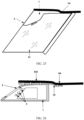
- FIG. 25 is a diagram of another structure that can expand accommodation space in the compartment housing 1. Specifically, a surface that is of the compartment housing 1 and that faces the top of the driver's cab 04 may protrude in a direction toward the top of the driver's cab, to expand the space in the compartment housing 1.
- the compartment housing 1 of the sensor compartment 06 may be further fastened to the top 041 of the driver's cab 04. In this way, connection reliability and stability of the sensor compartment 06 can be further improved.
- FIG. 26 and FIG. 27 each show a manner of fastening the compartment housing 1 of the sensor compartment 06 to the driver's cab 04.
- the compartment housing 1 is fastened to the driver's cab 04 by using an installation bracket 15.
- a side surface that is of the compartment housing 1 and that faces the top of the driver's cab 04 is fastened to the top 041 of the driver's cab 04 by using the installation bracket 15.
- the installation bracket 15 may be fastened to the top 041 of the driver's cab 04 by using an adhesive layer, and then the compartment housing 1 is fastened to the installation bracket 15 by using the adhesive layer, to fasten the compartment housing 1 to the driver's cab 04.
- the installation bracket 15 may be fastened to the compartment housing 1 and the driver's cab 04 by using a connection member (for example, a bolt or a rivet).
- the installation bracket 15 in this application and the compartment housing 1 may be two independent mechanical members.
- the installation bracket 15 may be a mechanical member integrated with the compartment housing 1. Such a design can simplify an assembly process of the sensor compartment 06 and the driver's cab 04.
- FIG. 26 a difference lies in that in FIG. 26 , the part that is of the top 041 of the driver's cab 04 and that is for fastening the compartment housing 1 may protrude toward the outside of the driver's cab, to form a protrusion part shown in FIG. 26 . In this way, larger placement space may be reserved for the sensor compartment 06, to expand space in the compartment housing 1. Further, more sensors or another component may be disposed in the compartment housing 1.
- the part that is of the top 041 of the driver's cab 04 and that is for fastening the compartment housing 1 does not protrude toward the outside of the driver's cab, but is located on a same plane as the other part.
- the foregoing explains a structure of the sensor compartment 06 and an installation manner of the optical sensor 4 in the sensor compartment 06.
- the sensor compartment 06 may be assembled based on the following method.
- structures such as the optical sensor 4, the compartment window cleaning apparatus, the compartment window heating apparatus, the compartment housing dehumidification apparatus, and the compartment housing heat dissipation apparatus may be installed in the compartment housing 1 of the sensor compartment 06.
- the embedding groove that is of the windshield and that is configured to install the sensor compartment 06 may be cleaned, to remove a foreign matter at a position that is on the embedding groove and that is in contact with the sensor compartment.
- the sensor compartment 06 is installed in the embedding groove, and the position that is on the compartment housing 1 and that is in contact with the windshield is sealed.
Landscapes
- Engineering & Computer Science (AREA)
- Physics & Mathematics (AREA)
- General Physics & Mathematics (AREA)
- Radar, Positioning & Navigation (AREA)
- Remote Sensing (AREA)
- Computer Networks & Wireless Communication (AREA)
- Multimedia (AREA)
- Mechanical Engineering (AREA)
- Electromagnetism (AREA)
- Optics & Photonics (AREA)
- Investigating Or Analysing Materials By Optical Means (AREA)
- Optical Radar Systems And Details Thereof (AREA)
Applications Claiming Priority (1)
| Application Number | Priority Date | Filing Date | Title |
|---|---|---|---|
| PCT/CN2022/089609 WO2023206153A1 (zh) | 2022-04-27 | 2022-04-27 | 传感器舱体、驾驶设备、传感器舱体的安装方法 |
Publications (2)
| Publication Number | Publication Date |
|---|---|
| EP4497635A1 true EP4497635A1 (de) | 2025-01-29 |
| EP4497635A4 EP4497635A4 (de) | 2025-07-30 |
Family
ID=88516666
Family Applications (1)
| Application Number | Title | Priority Date | Filing Date |
|---|---|---|---|
| EP22939006.7A Pending EP4497635A4 (de) | 2022-04-27 | 2022-04-27 | Sensorkabine, antriebsvorrichtung und installationsverfahren für sensorkabine |
Country Status (4)
| Country | Link |
|---|---|
| US (1) | US20250050820A1 (de) |
| EP (1) | EP4497635A4 (de) |
| CN (1) | CN118984784A (de) |
| WO (1) | WO2023206153A1 (de) |
Cited By (1)
| Publication number | Priority date | Publication date | Assignee | Title |
|---|---|---|---|---|
| US20240317027A1 (en) * | 2023-03-24 | 2024-09-26 | Honda Motor Co., Ltd. | Vehicle |
Family Cites Families (19)
| Publication number | Priority date | Publication date | Assignee | Title |
|---|---|---|---|---|
| US5414257A (en) * | 1991-04-23 | 1995-05-09 | Introlab Pty Limited | Moisture sensor for detecting moisture on a windshield |
| DE4329983B4 (de) * | 1993-09-04 | 2004-12-02 | Robert Bosch Gmbh | Dachmodul für ein Kraftfahrzeug |
| US20070216768A1 (en) * | 2006-03-14 | 2007-09-20 | Ford Global Technologies, Llc | Device and method for outwardly looking ir camera mounted inside vehicles particularly suited for pre-crash sensing and pedestrian detection |
| DE102008023845B4 (de) * | 2008-05-16 | 2018-04-05 | Trw Automotive Electronics & Components Gmbh | Optische Sensorvorrichtung zur Detektion von Umgebungslicht |
| CN102116620B (zh) * | 2009-12-31 | 2013-03-20 | 北京卫星环境工程研究所 | 用于真空低温环境下ccd摄影测量的保护舱 |
| CN102123240B (zh) * | 2010-12-21 | 2015-04-08 | 天津市亚安科技股份有限公司 | 一种摄像机防护罩雨刷器及视频监控系统 |
| JP6413754B2 (ja) * | 2014-03-10 | 2018-10-31 | 株式会社デンソー | 撮像装置および撮像装置を備えた車載装置 |
| WO2017188414A1 (ja) * | 2016-04-27 | 2017-11-02 | 旭硝子株式会社 | 樹脂体及びガラス板物品 |
| JP6575472B2 (ja) * | 2016-09-13 | 2019-09-18 | トヨタ自動車株式会社 | 車載光学センサ装置 |
| CN107351780A (zh) * | 2017-08-16 | 2017-11-17 | 深圳前海恒胜车联网信息有限公司 | 一种挪车提醒装置 |
| US10823824B2 (en) * | 2017-11-20 | 2020-11-03 | Ford Global Technologies, Llc | Sensor assembly |
| DE102018125065B3 (de) * | 2018-10-10 | 2019-11-21 | Bayerische Motoren Werke Aktiengesellschaft | Haltevorrichtung zur Halterung wenigstens einer Fahrerassistenzsensoreinheit sowie Anordnung einer Haltevorrichtung |
| KR102649667B1 (ko) * | 2019-01-15 | 2024-03-20 | 쌩-고벵 글래스 프랑스 | 통합된 센서모듈을 갖는 차량 창 |
| CN210000220U (zh) * | 2019-03-15 | 2020-01-31 | 郑永宏 | 一种车灯自动控制装置 |
| US11150669B2 (en) * | 2019-06-10 | 2021-10-19 | Pony Ai Inc. | System and method for regulating a sensor enclosure |
| CN211032413U (zh) * | 2019-10-11 | 2020-07-17 | 苏州智加科技有限公司 | 一种用于自动行驶的摄像装置及自动行驶汽车 |
| KR102728786B1 (ko) * | 2019-10-25 | 2024-11-11 | 현대모비스 주식회사 | 센서 클러스터장치 및 그를 포함하는 자동차 |
| CN111186387A (zh) * | 2020-03-11 | 2020-05-22 | 北京觉非科技有限公司 | 一种车载移动高精度采集装置 |
| CN213109202U (zh) * | 2020-06-11 | 2021-05-04 | 上海中科深江电动车辆有限公司 | 一种传感器装置及车辆 |
-
2022
- 2022-04-27 EP EP22939006.7A patent/EP4497635A4/de active Pending
- 2022-04-27 WO PCT/CN2022/089609 patent/WO2023206153A1/zh not_active Ceased
- 2022-04-27 CN CN202280093246.0A patent/CN118984784A/zh active Pending
-
2024
- 2024-10-24 US US18/926,105 patent/US20250050820A1/en active Pending
Cited By (1)
| Publication number | Priority date | Publication date | Assignee | Title |
|---|---|---|---|---|
| US20240317027A1 (en) * | 2023-03-24 | 2024-09-26 | Honda Motor Co., Ltd. | Vehicle |
Also Published As
| Publication number | Publication date |
|---|---|
| EP4497635A4 (de) | 2025-07-30 |
| US20250050820A1 (en) | 2025-02-13 |
| CN118984784A (zh) | 2024-11-19 |
| WO2023206153A1 (zh) | 2023-11-02 |
Similar Documents
| Publication | Publication Date | Title |
|---|---|---|
| US10843668B2 (en) | Device for protecting an optical sensor, and associated driver assistance system and cleaning method | |
| JP6304205B2 (ja) | 車載撮像装置 | |
| US20250050820A1 (en) | Sensor compartment, driving device, and sensor compartment installation method | |
| US20070216768A1 (en) | Device and method for outwardly looking ir camera mounted inside vehicles particularly suited for pre-crash sensing and pedestrian detection | |
| US20200290516A1 (en) | Combined approach lamp and logo lamp | |
| JP4045871B2 (ja) | 車両搭載カメラのカメラカバー | |
| US10759348B2 (en) | Rear view assembly for a motor vehicle with interchangeable approach lamp | |
| KR20120046731A (ko) | 광학적으로 투명한 센서 장을 갖는 창유리 | |
| US12441254B2 (en) | Holding device for holding at least one driver assist sensor unit, and arrangement of a holding device | |
| US20210219467A1 (en) | Thermal coupling of surroundings sensors in the vehicle roof to the vehicle passenger compartment climate | |
| US20090245767A1 (en) | Lens assembly and imaging device | |
| CN108791203B (zh) | 机动车的传感器装置、机动车及运行传感器装置的方法 | |
| CN116605020A (zh) | 顶部组件以及包括这种顶部组件的机动车 | |
| JP7661101B2 (ja) | ウインドシールド装置 | |
| US20040179098A1 (en) | Image reversing for infrared camera | |
| CN114537292B (zh) | 车辆相机安装组件 | |
| KR102751215B1 (ko) | 크리닝 분사 노즐과 자율주행센서가 일체화된 차량용 램프 시스템 | |
| CN213305539U (zh) | 无人驾驶车及前视摄像头集成件总成 | |
| JP2007069771A (ja) | 車両用ヘッドアップディスプレイ装置 | |
| JP5132908B2 (ja) | 車載用カメラ | |
| CN220130083U (zh) | 一种自动清洁的汽车后视镜以及汽车 | |
| JP2005014858A (ja) | カメラ内蔵ドアミラー | |
| CN111746467A (zh) | 车辆 | |
| JP2002044497A (ja) | 車載撮像装置 | |
| WO2020181416A1 (zh) | 一种车辆以及用于安装于车辆的侧后视镜 |
Legal Events
| Date | Code | Title | Description |
|---|---|---|---|
| STAA | Information on the status of an ep patent application or granted ep patent |
Free format text: STATUS: THE INTERNATIONAL PUBLICATION HAS BEEN MADE |
|
| PUAI | Public reference made under article 153(3) epc to a published international application that has entered the european phase |
Free format text: ORIGINAL CODE: 0009012 |
|
| STAA | Information on the status of an ep patent application or granted ep patent |
Free format text: STATUS: REQUEST FOR EXAMINATION WAS MADE |
|
| 17P | Request for examination filed |
Effective date: 20241023 |
|
| AK | Designated contracting states |
Kind code of ref document: A1 Designated state(s): AL AT BE BG CH CY CZ DE DK EE ES FI FR GB GR HR HU IE IS IT LI LT LU LV MC MK MT NL NO PL PT RO RS SE SI SK SM TR |
|
| RIC1 | Information provided on ipc code assigned before grant |
Ipc: G01S 7/497 20060101ALI20250402BHEP Ipc: G01S 17/86 20200101ALI20250402BHEP Ipc: B60R 11/04 20060101ALI20250402BHEP Ipc: G01S 17/931 20200101ALI20250402BHEP Ipc: G01S 7/481 20060101ALI20250402BHEP Ipc: G02B 27/00 20060101ALI20250402BHEP Ipc: B60S 1/46 20060101ALI20250402BHEP Ipc: B60S 1/04 20060101ALI20250402BHEP Ipc: B60R 13/00 20060101ALI20250402BHEP Ipc: B60R 1/00 20220101AFI20250402BHEP |
|
| A4 | Supplementary search report drawn up and despatched |
Effective date: 20250702 |
|
| RIC1 | Information provided on ipc code assigned before grant |
Ipc: B60R 1/00 20220101AFI20250626BHEP Ipc: B60R 13/00 20060101ALI20250626BHEP Ipc: B60S 1/04 20060101ALI20250626BHEP Ipc: B60S 1/46 20060101ALI20250626BHEP Ipc: G02B 27/00 20060101ALI20250626BHEP Ipc: G01S 7/481 20060101ALI20250626BHEP Ipc: G01S 17/931 20200101ALI20250626BHEP Ipc: B60R 11/04 20060101ALI20250626BHEP Ipc: G01S 17/86 20200101ALI20250626BHEP Ipc: G01S 7/497 20060101ALI20250626BHEP |
|
| DAV | Request for validation of the european patent (deleted) | ||
| DAX | Request for extension of the european patent (deleted) | ||
| RAP3 | Party data changed (applicant data changed or rights of an application transferred) |
Owner name: YINWANG INTELLIGENT TECHNOLOGIES CO., LTD. |