EP4491362A2 - Verfahren und vorrichtungen zur herstellung von strohplatten und kalkhydrat-zuführeinrichtung dafür - Google Patents
Verfahren und vorrichtungen zur herstellung von strohplatten und kalkhydrat-zuführeinrichtung dafür Download PDFInfo
- Publication number
- EP4491362A2 EP4491362A2 EP24183027.2A EP24183027A EP4491362A2 EP 4491362 A2 EP4491362 A2 EP 4491362A2 EP 24183027 A EP24183027 A EP 24183027A EP 4491362 A2 EP4491362 A2 EP 4491362A2
- Authority
- EP
- European Patent Office
- Prior art keywords
- straw
- mixer
- mixing
- screw
- blade
- Prior art date
- Legal status (The legal status is an assumption and is not a legal conclusion. Google has not performed a legal analysis and makes no representation as to the accuracy of the status listed.)
- Granted
Links
Images









Classifications
-
- B—PERFORMING OPERATIONS; TRANSPORTING
- B28—WORKING CEMENT, CLAY, OR STONE
- B28C—PREPARING CLAY; PRODUCING MIXTURES CONTAINING CLAY OR CEMENTITIOUS MATERIAL, e.g. PLASTER
- B28C5/00—Apparatus or methods for producing mixtures of cement with other substances, e.g. slurries, mortars, porous or fibrous compositions
- B28C5/40—Mixing specially adapted for preparing mixtures containing fibres
- B28C5/404—Pre-treatment of fibres
- B28C5/406—Pre-treatment of fibres and mixing with binding material
-
- B—PERFORMING OPERATIONS; TRANSPORTING
- B01—PHYSICAL OR CHEMICAL PROCESSES OR APPARATUS IN GENERAL
- B01F—MIXING, e.g. DISSOLVING, EMULSIFYING OR DISPERSING
- B01F27/00—Mixers with rotary stirring devices in fixed receptacles; Kneaders
- B01F27/05—Stirrers
- B01F27/11—Stirrers characterised by the configuration of the stirrers
- B01F27/17—Stirrers with additional elements mounted on the stirrer, for purposes other than mixing
- B01F27/172—Stirrers with additional elements mounted on the stirrer, for purposes other than mixing for cutting, e.g. with knives
-
- B—PERFORMING OPERATIONS; TRANSPORTING
- B01—PHYSICAL OR CHEMICAL PROCESSES OR APPARATUS IN GENERAL
- B01F—MIXING, e.g. DISSOLVING, EMULSIFYING OR DISPERSING
- B01F27/00—Mixers with rotary stirring devices in fixed receptacles; Kneaders
- B01F27/60—Mixers with rotary stirring devices in fixed receptacles; Kneaders with stirrers rotating about a horizontal or inclined axis
- B01F27/72—Mixers with rotary stirring devices in fixed receptacles; Kneaders with stirrers rotating about a horizontal or inclined axis with helices or sections of helices
- B01F27/721—Mixers with rotary stirring devices in fixed receptacles; Kneaders with stirrers rotating about a horizontal or inclined axis with helices or sections of helices with two or more helices in the same receptacle
-
- B—PERFORMING OPERATIONS; TRANSPORTING
- B01—PHYSICAL OR CHEMICAL PROCESSES OR APPARATUS IN GENERAL
- B01F—MIXING, e.g. DISSOLVING, EMULSIFYING OR DISPERSING
- B01F27/00—Mixers with rotary stirring devices in fixed receptacles; Kneaders
- B01F27/60—Mixers with rotary stirring devices in fixed receptacles; Kneaders with stirrers rotating about a horizontal or inclined axis
- B01F27/72—Mixers with rotary stirring devices in fixed receptacles; Kneaders with stirrers rotating about a horizontal or inclined axis with helices or sections of helices
- B01F27/726—Mixers with rotary stirring devices in fixed receptacles; Kneaders with stirrers rotating about a horizontal or inclined axis with helices or sections of helices with two helices with opposite pitch on the same shaft; with two helices on the same axis, driven in opposite directions or at different speeds
-
- B—PERFORMING OPERATIONS; TRANSPORTING
- B01—PHYSICAL OR CHEMICAL PROCESSES OR APPARATUS IN GENERAL
- B01F—MIXING, e.g. DISSOLVING, EMULSIFYING OR DISPERSING
- B01F35/00—Accessories for mixers; Auxiliary operations or auxiliary devices; Parts or details of general application
- B01F35/45—Closures or doors specially adapted for mixing receptacles; Operating mechanisms therefor
- B01F35/452—Closures or doors specially adapted for mixing receptacles; Operating mechanisms therefor by moving them in the plane of the opening
-
- B—PERFORMING OPERATIONS; TRANSPORTING
- B28—WORKING CEMENT, CLAY, OR STONE
- B28B—SHAPING CLAY OR OTHER CERAMIC COMPOSITIONS; SHAPING SLAG; SHAPING MIXTURES CONTAINING CEMENTITIOUS MATERIAL, e.g. PLASTER
- B28B1/00—Producing shaped prefabricated articles from the material
- B28B1/52—Producing shaped prefabricated articles from the material specially adapted for producing articles from mixtures containing fibres, e.g. asbestos cement
- B28B1/525—Producing shaped prefabricated articles from the material specially adapted for producing articles from mixtures containing fibres, e.g. asbestos cement containing organic fibres, e.g. wood fibres
-
- B—PERFORMING OPERATIONS; TRANSPORTING
- B28—WORKING CEMENT, CLAY, OR STONE
- B28B—SHAPING CLAY OR OTHER CERAMIC COMPOSITIONS; SHAPING SLAG; SHAPING MIXTURES CONTAINING CEMENTITIOUS MATERIAL, e.g. PLASTER
- B28B1/00—Producing shaped prefabricated articles from the material
- B28B1/52—Producing shaped prefabricated articles from the material specially adapted for producing articles from mixtures containing fibres, e.g. asbestos cement
- B28B1/526—Producing shaped prefabricated articles from the material specially adapted for producing articles from mixtures containing fibres, e.g. asbestos cement by delivering the materials on a conveyor of the endless-belt type
-
- B—PERFORMING OPERATIONS; TRANSPORTING
- B28—WORKING CEMENT, CLAY, OR STONE
- B28B—SHAPING CLAY OR OTHER CERAMIC COMPOSITIONS; SHAPING SLAG; SHAPING MIXTURES CONTAINING CEMENTITIOUS MATERIAL, e.g. PLASTER
- B28B15/00—General arrangement or layout of plant ; Industrial outlines or plant installations
-
- B—PERFORMING OPERATIONS; TRANSPORTING
- B28—WORKING CEMENT, CLAY, OR STONE
- B28B—SHAPING CLAY OR OTHER CERAMIC COMPOSITIONS; SHAPING SLAG; SHAPING MIXTURES CONTAINING CEMENTITIOUS MATERIAL, e.g. PLASTER
- B28B3/00—Producing shaped articles from the material by using presses; Presses specially adapted therefor
- B28B3/12—Producing shaped articles from the material by using presses; Presses specially adapted therefor wherein one or more rollers exert pressure on the material
- B28B3/123—Producing shaped articles from the material by using presses; Presses specially adapted therefor wherein one or more rollers exert pressure on the material on material in moulds or on moulding surfaces moving continuously underneath or between the rollers, e.g. on an endless belt
-
- B—PERFORMING OPERATIONS; TRANSPORTING
- B28—WORKING CEMENT, CLAY, OR STONE
- B28C—PREPARING CLAY; PRODUCING MIXTURES CONTAINING CLAY OR CEMENTITIOUS MATERIAL, e.g. PLASTER
- B28C5/00—Apparatus or methods for producing mixtures of cement with other substances, e.g. slurries, mortars, porous or fibrous compositions
- B28C5/08—Apparatus or methods for producing mixtures of cement with other substances, e.g. slurries, mortars, porous or fibrous compositions using driven mechanical means affecting the mixing
- B28C5/0881—Apparatus or methods for producing mixtures of cement with other substances, e.g. slurries, mortars, porous or fibrous compositions using driven mechanical means affecting the mixing having a stator-rotor system with intermeshing teeth or cages
-
- B—PERFORMING OPERATIONS; TRANSPORTING
- B28—WORKING CEMENT, CLAY, OR STONE
- B28C—PREPARING CLAY; PRODUCING MIXTURES CONTAINING CLAY OR CEMENTITIOUS MATERIAL, e.g. PLASTER
- B28C5/00—Apparatus or methods for producing mixtures of cement with other substances, e.g. slurries, mortars, porous or fibrous compositions
- B28C5/08—Apparatus or methods for producing mixtures of cement with other substances, e.g. slurries, mortars, porous or fibrous compositions using driven mechanical means affecting the mixing
- B28C5/10—Mixing in containers not actuated to effect the mixing
- B28C5/12—Mixing in containers not actuated to effect the mixing with stirrers sweeping through the materials, e.g. with incorporated feeding or discharging means or with oscillating stirrers
- B28C5/14—Mixing in containers not actuated to effect the mixing with stirrers sweeping through the materials, e.g. with incorporated feeding or discharging means or with oscillating stirrers the stirrers having motion about a horizontal or substantially horizontal axis
- B28C5/142—Mixing in containers not actuated to effect the mixing with stirrers sweeping through the materials, e.g. with incorporated feeding or discharging means or with oscillating stirrers the stirrers having motion about a horizontal or substantially horizontal axis the stirrer shaft carrying screw-blades
- B28C5/143—Mixing in containers not actuated to effect the mixing with stirrers sweeping through the materials, e.g. with incorporated feeding or discharging means or with oscillating stirrers the stirrers having motion about a horizontal or substantially horizontal axis the stirrer shaft carrying screw-blades for materials flowing continuously through the mixing device
-
- B—PERFORMING OPERATIONS; TRANSPORTING
- B28—WORKING CEMENT, CLAY, OR STONE
- B28C—PREPARING CLAY; PRODUCING MIXTURES CONTAINING CLAY OR CEMENTITIOUS MATERIAL, e.g. PLASTER
- B28C5/00—Apparatus or methods for producing mixtures of cement with other substances, e.g. slurries, mortars, porous or fibrous compositions
- B28C5/08—Apparatus or methods for producing mixtures of cement with other substances, e.g. slurries, mortars, porous or fibrous compositions using driven mechanical means affecting the mixing
- B28C5/10—Mixing in containers not actuated to effect the mixing
- B28C5/12—Mixing in containers not actuated to effect the mixing with stirrers sweeping through the materials, e.g. with incorporated feeding or discharging means or with oscillating stirrers
- B28C5/14—Mixing in containers not actuated to effect the mixing with stirrers sweeping through the materials, e.g. with incorporated feeding or discharging means or with oscillating stirrers the stirrers having motion about a horizontal or substantially horizontal axis
- B28C5/146—Mixing in containers not actuated to effect the mixing with stirrers sweeping through the materials, e.g. with incorporated feeding or discharging means or with oscillating stirrers the stirrers having motion about a horizontal or substantially horizontal axis with several stirrers with parallel shafts in one container
- B28C5/147—Mixing in containers not actuated to effect the mixing with stirrers sweeping through the materials, e.g. with incorporated feeding or discharging means or with oscillating stirrers the stirrers having motion about a horizontal or substantially horizontal axis with several stirrers with parallel shafts in one container the material being moved perpendicularly to the axis of the shafts
-
- B—PERFORMING OPERATIONS; TRANSPORTING
- B28—WORKING CEMENT, CLAY, OR STONE
- B28C—PREPARING CLAY; PRODUCING MIXTURES CONTAINING CLAY OR CEMENTITIOUS MATERIAL, e.g. PLASTER
- B28C5/00—Apparatus or methods for producing mixtures of cement with other substances, e.g. slurries, mortars, porous or fibrous compositions
- B28C5/08—Apparatus or methods for producing mixtures of cement with other substances, e.g. slurries, mortars, porous or fibrous compositions using driven mechanical means affecting the mixing
- B28C5/10—Mixing in containers not actuated to effect the mixing
- B28C5/12—Mixing in containers not actuated to effect the mixing with stirrers sweeping through the materials, e.g. with incorporated feeding or discharging means or with oscillating stirrers
- B28C5/16—Mixing in containers not actuated to effect the mixing with stirrers sweeping through the materials, e.g. with incorporated feeding or discharging means or with oscillating stirrers the stirrers having motion about a vertical or steeply inclined axis
-
- B—PERFORMING OPERATIONS; TRANSPORTING
- B28—WORKING CEMENT, CLAY, OR STONE
- B28C—PREPARING CLAY; PRODUCING MIXTURES CONTAINING CLAY OR CEMENTITIOUS MATERIAL, e.g. PLASTER
- B28C5/00—Apparatus or methods for producing mixtures of cement with other substances, e.g. slurries, mortars, porous or fibrous compositions
- B28C5/40—Mixing specially adapted for preparing mixtures containing fibres
- B28C5/402—Methods
-
- B—PERFORMING OPERATIONS; TRANSPORTING
- B28—WORKING CEMENT, CLAY, OR STONE
- B28C—PREPARING CLAY; PRODUCING MIXTURES CONTAINING CLAY OR CEMENTITIOUS MATERIAL, e.g. PLASTER
- B28C7/00—Controlling the operation of apparatus for producing mixtures of clay or cement with other substances; Supplying or proportioning the ingredients for mixing clay or cement with other substances; Discharging the mixture
- B28C7/04—Supplying or proportioning the ingredients
- B28C7/0422—Weighing predetermined amounts of ingredients, e.g. for consecutive delivery
- B28C7/0445—Weighing predetermined amounts of ingredients, e.g. for consecutive delivery using a weighing receptacle, the feeding thereof being automatically suspended after a predetermined weight has been obtained
-
- B—PERFORMING OPERATIONS; TRANSPORTING
- B28—WORKING CEMENT, CLAY, OR STONE
- B28C—PREPARING CLAY; PRODUCING MIXTURES CONTAINING CLAY OR CEMENTITIOUS MATERIAL, e.g. PLASTER
- B28C7/00—Controlling the operation of apparatus for producing mixtures of clay or cement with other substances; Supplying or proportioning the ingredients for mixing clay or cement with other substances; Discharging the mixture
- B28C7/16—Discharge means, e.g. with intermediate storage of fresh concrete
- B28C7/162—Discharge means, e.g. with intermediate storage of fresh concrete by means of conveyors, other than those comprising skips or containers, e.g. endless belts, screws, air under pressure
- B28C7/163—Discharge means, e.g. with intermediate storage of fresh concrete by means of conveyors, other than those comprising skips or containers, e.g. endless belts, screws, air under pressure using a pump
- B28C7/165—Discharge means, e.g. with intermediate storage of fresh concrete by means of conveyors, other than those comprising skips or containers, e.g. endless belts, screws, air under pressure using a pump using a fluid, e.g. gas
- B28C7/166—Discharge means, e.g. with intermediate storage of fresh concrete by means of conveyors, other than those comprising skips or containers, e.g. endless belts, screws, air under pressure using a pump using a fluid, e.g. gas comprising a lock rotor with pockets for feeding determined quantities of material from a hopper into the driving fluid
-
- B—PERFORMING OPERATIONS; TRANSPORTING
- B30—PRESSES
- B30B—PRESSES IN GENERAL
- B30B5/00—Presses characterised by the use of pressing means other than those mentioned in the preceding groups
- B30B5/04—Presses characterised by the use of pressing means other than those mentioned in the preceding groups wherein the pressing means is in the form of an endless band
- B30B5/06—Presses characterised by the use of pressing means other than those mentioned in the preceding groups wherein the pressing means is in the form of an endless band co-operating with another endless band
-
- B—PERFORMING OPERATIONS; TRANSPORTING
- B65—CONVEYING; PACKING; STORING; HANDLING THIN OR FILAMENTARY MATERIAL
- B65G—TRANSPORT OR STORAGE DEVICES, e.g. CONVEYORS FOR LOADING OR TIPPING, SHOP CONVEYOR SYSTEMS OR PNEUMATIC TUBE CONVEYORS
- B65G53/00—Conveying materials in bulk through troughs, pipes or tubes by floating the materials or by flow of gas, liquid or foam
- B65G53/34—Details
- B65G53/40—Feeding or discharging devices
- B65G53/46—Gates or sluices, e.g. rotary wheels
- B65G53/4608—Turnable elements, e.g. rotary wheels with pockets or passages for material
- B65G53/4625—Turnable elements, e.g. rotary wheels with pockets or passages for material with axis of turning perpendicular to flow
- B65G53/4633—Turnable elements, e.g. rotary wheels with pockets or passages for material with axis of turning perpendicular to flow the element having pockets, rotated from charging position to discharging position, i.e. discrete flow
Definitions
- the present invention relates to a method and devices for producing straw panels and a hydrated lime supply device therefor.
- the EP 2 799 639 A1 discloses an insulation board for insulating a building facade, wherein the insulation board is made of straw which is held together by means of an adhesive.
- the adhesive can be glue, in particular vegetable glue, or starch glue.
- the insulation board is produced by mixing preferably chopped straw with the adhesive, gently pressing the straw-adhesive mixture to form an insulation board and allowing the insulation board produced in this way to stand so that it can dry out. To dry out, the insulation board is preferably heated, in particular to a temperature of approx. 25 - 50 °C.
- the result is an insulation board made of straw in which the straw fibre length is a maximum of 150 mm, the straw is shredded into fibrous pieces and the closed stalk structure is destroyed by longitudinal splicing, the straw fibres are homogeneously mixed with a biodegradable binding agent, the mixture of straw fibres and binding agent is slightly mechanically compacted to form board material, the minimum thickness of the board is 30 mm and the bulk density is 40 to 100 kg/m 3.
- the board is also provided with a flexible, grid-like natural fibre coating on both sides.
- the straw fibres are preferably largely at least 2 mm long or more.
- the insulation board is manufactured by shredding the straw into fibrous pieces and splicing the straw lengthwise to form a fraction with fibre lengths of up to 150 mm.
- the fibre fraction is then mixed homogeneously with a biodegradable binder containing excess water and the mixture is continuously applied to a sheet of coating material soaked in binder, with slight deformation.
- the fibre fraction is preferably mixed with binder and flame retardant in a mixing device.
- the homogeneous mixture is then conveyed by a conveyor belt into a mixing silo, which has a discharge roller at the lower end and is arranged above a plate conveyor belt on which the impregnated web of coating material is arranged.
- An upper coating layer soaked in binding agent is placed on the resulting insulation sheet and the resulting insulation sheet is conveyed through a heating zone and dried and, if necessary, vulcanized. This is preferably done using a hot air flow process with a hot air temperature of around 100°C. During drying, the binding agent is dried or vulcanized, with the water vapor that forms serving as a heat carrier and promoting vulcanization. The dried sheet is then cut into panels.
- the object of the present invention is to provide a cost-effective method and a device for producing straw panels, which ensures a uniform and good quality of the straw panels produced.
- a further task is to provide a hydrated lime feeding device for the precise addition of hydrated lime to the straw.
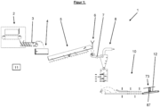
- the device 1 according to the invention is used to produce straw panels 12; 13.
- the straw panels 12; 13 to be produced are preferably single-layered or monolithic and consist of straw which is held together with a hardened binding agent matrix.
- the binding agent matrix connects the individual straws to one another.
- the device 1 is used for producing insulating straw panels 12 or straw insulation panels 12 and has a straw bale breaking up device 2, a conveyor channel 3, a weighing device 4, a vibrating trough 5, a lime hydrate feed device 6, preferably a further conveyor channel 7, preferably a cyclone separator (50), a mixing device 8 according to the invention and preferably a further conveyor channel 9 and an insulation panel pressing device 10.
- the device 1 has a control device 11 for controlling the production process.
- Subordinate in the sense of the application means that the respective facility is passed through after the upstream facility during production.
- the straw bale dissolving device 2 ( Fig. 1 , 2 , 3 ) serves in a manner known per se for dissolving and loosening a straw bale 15.
- Straw generally refers to threshed and dry stalks and/or leaves of plants.
- Such straw bale breaking devices 2 are used, for example, in horse stables. By means of the straw bale breaking device 2, the straw bales 15 are broken up and loosened without the straw stalks being shredded.
- the straw bale breaking device 2 preferably has, in a manner known per se, a housing 16, a milling belt 17, an abutment plate 18, a receiving hopper 19 and a discharge conveyor screw 20.
- the milling belt 17, the abutment plate 18 and the receiving hopper 19 are arranged in the housing 16.
- the discharge conveyor screw 20 is partially arranged in the housing 16 and opens into the environment or leads outside.
- the straw bale 15 is placed on the rotating milling belt 17 and pressed by it against the abutment plate 18, which is arranged above the end of the horizontal milling belt 17.
- the straw bale 15 is broken up by means of the milling edges 21 of the milling belt 17 and the broken up and loosened straw 22 falls down from the milling belt 17 into the receiving hopper 19 at the end of the milling belt 17.
- the receiving hopper 19 in turn opens into the discharge conveyor screw 20, which conveys the straw 22 out of the housing 16 into the conveyor channel 3.
- grains and other fine particles that arise when the straw bale 15 is broken up are also sucked out of the housing 16.
- the straw 22 is conveyed into the conveying channel 3 and through it to the weighing device 4.
- the conveying takes place solely by the conveying pressure generated by the discharge conveyor screw 20.
- the conveyor channel 3 preferably also has a sensor 23 for detecting or measuring the conveying pressure.
- the conveyor channel 3 has a milling roller 24 and a deflection hood 25 at the end on the weighing device side.
- the detection of the delivery pressure serves to keep the delivery quantity constant. If deviations from the target delivery pressure are detected, the straw bale dissolving device 2 is controlled in such a way that it provides more or less straw 22. The straw bale dissolving device 2 is therefore controlled, among other things, on the basis of the delivery pressure measured by the sensor 23.
- the straw 22 is conveyed in portions into the weighing device 4.
- the milling roller 24 has milling edges 24a in a manner known per se.
- individual straw portions are separated from the straw composite and one straw portion is placed between two adjacent milling edges 24a and conveyed into the weighing device 4.
- the straw 22 is deflected or guided by means of the deflection hood 25 in such a way that it falls into the weighing device 4.
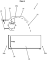
- the weighing device 4 ( Fig. 1 , 2 , 4 , 5 ) has a U-shaped tub 26 with a first and a second tub end 26a;b, a frame 27 and a dozer blade 28.
- the frame 27 is set up on the ground and the tub 26 is suspended from the frame 27 by means of four load cells 29 which are connected to the control device 11.
- the straw 22 is now conveyed into the trough 26 in portions by means of the milling roller 24 and weighed therein.
- the vertical clearing blade 28 is arranged at the first end 26a of the trough facing the milling roller 24 and closes off the trough 26.
- straw 22 is fed into the trough 26 in portions until the desired amount of straw 22 is reached.
- This is preferably 2.0 to 10.0 kg, preferably 2.1 to 4.2 kg.
- the milling roller 24 is stopped and the weighed straw portion is pushed out of the trough 26 by means of the clearing blade 28.
- the clearing blade 28 is moved from the first trough end 26 to the second trough end 26b and the straw 22 is thereby pushed out of the trough 26 at the second trough end 26a and conveyed into the vibrating trough 5.
- the vibrating channel 5 ( Fig. 1 , 2 , 6 ) has a U-shaped channel wall 30 which is attached to the ground by means of throwing arms 31.
- the vibrating channel 5 has a first, lower channel end 5a facing the weighing device 4 and a second, upper channel end 5b.
- the vibrating channel 5 is therefore preferably not horizontal but rather designed to rise. It conveys the straw 22 from bottom to top, from the lower channel end 5a to the upper channel end 5b.
- the channel wall 30 is attached to the ground by means of the throwing arms 31.
- the throwing arms 31 are attached to the ground at one end so that they can rotate about a horizontal axis and at the other end to the channel wall 30 so that they can rotate about a horizontal axis.
- the vibrating channel 5 has at least one drive arm 32, preferably two drive arms 32 on each side.
- the drive arm 32 is attached at one end to the channel wall 30 and at the other end eccentrically to a drive disk 33, which in turn is connected to a drive motor so that it can rotate.
- the straw 22 is conveyed in a manner known per se by the shaking or rocking movement of the vibrating trough 5. This causes the straw 22 to be thrown forwards at regular intervals in a trough conveying direction 5b and at the same time homogenized. This homogenization is important in order to achieve a constant mass flow of the straw 22, which was previously portioned during weighing. As a result, the vibrating trough 5 serves to convey the straw 22 and to homogenize the mass flow of the straw 22. For this reason, it is also operated continuously.
- the addition of lime hydrate dust to the straw 22 now takes place at the upper channel end 5b.
- the lime hydrate feed device 6 is arranged at the upper channel end 5b above the channel wall 30.
- the trough wall 30 has a discharge edge 34 at the upper trough end 5, from which the straw 22 falls down.
- a trough bottom 30a of the trough wall 30 at the upper trough end 5b has a downward bend so that the straw 22 falls out of the trough wall 30 more easily.
- the trough bottom 30a also preferably has a non-slip, preferably sandy, floor surface on the inside in order to be able to transport the light and smooth straw 22 by the throwing movement.
- the straw 22 falls from the channel wall 30 into a collecting funnel 35 of a radial blower 36, which is arranged at the beginning of the further conveying channel 7.
- the hydrated lime feed device 6 is used, as already explained, for the addition of very fine, dust-like hydrated lime (Ca(OH) 2 ).
- the hydrated lime has a grain size of ⁇ 100 ⁇ m, preferably ⁇ 90 ⁇ m, in accordance with DIN EN 459-1:2015-07.
- the hydrated lime is used to adjust certain properties of the straw insulation boards 12 to be produced.
- the pH value and the color of the straw insulation boards 12 can be influenced.
- the hydrated lime strengthens the binding properties of the binder and influences the surface hardness of the straw insulation boards 12.
- the hydrated lime feed device 6 preferably has a special design:
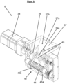
- the lime hydrate feed device 6 ( Fig. 1 , 2 , 7 , 8 , 9 ) has a storage container 37 for holding the lime hydrate, a drive motor 38, a mixer shaft 39 with mixer rods 40, and a rotary valve 41 with a blow-out mechanism or a blow-out device 46.
- the storage container 37 is preferably funnel-shaped, tapering downwards and open at the top. In addition, it has a container wall 37a and a container interior 37b.
- the mixer shaft 39 extends horizontally and through the container interior 37b. It is also mounted at both ends in the container wall 37a so that it can rotate about its horizontal mixer shaft axis of rotation 39a.
- the mixer shaft 39 is rotatable about its mixer shaft axis of rotation 39a drivable in connection with the drive motor 38.
- the mixer rods 40 extend in the radial direction away from the mixer shaft 39 in relation to the mixer shaft rotation axis 39a.
- the mixer shaft 39 with the mixer rods 40 is arranged above the cell wheel 42. It serves to loosen the hydrated lime in the storage container 37 and improves the trickling of the hydrated lime onto the cell wheel 42.
- the drive motor 38 is preferably a stepper motor.
- the stepper motor ensures a precise speed and thus a precise dosage of the hydrated lime.
- it can also be a servo motor. It can also be a direct current motor or a three-phase motor.
- the drive motor 38 is preferably attached to the outside of the storage container 37.
- the rotary valve 41 is arranged below the mixer shaft 39. It has a rotating rotary valve 42, a valve housing 43, a valve inlet 41a and a valve outlet 41b.
- the valve inlet 41a is arranged vertically aligned below the mixer shaft 39.
- lock housing 43 is part of the container wall 37a.
- the cell wheel 42 has a cell wheel rotation axis 42a and several cells 44 adjacent to one another in the circumferential direction for receiving the lime hydrate.
- the cells 44 are designed in the form of grooves and have a longitudinal extension parallel to the cell wheel rotation axis 42a.
- the cells 44 extend into the cell wheel 42 in the radial direction in relation to the cell wheel rotation axis 42a.
- a cell wall of the cells 44 preferably has a circular arc-shaped, preferably semicircular, cross-section.
- the cross-section extends over a maximum of 180° or a semicircle.
- the cells 44 each have a volume of 300 mm 3 to 3000 mm 3 , preferably 400 mm 3 to 800 mm 3 .
- the cell wheel 42 preferably has a delivery rate of 10,000 mm 3 /min to 500,000 mm 3 /min, preferably 30,000 mm 3 /min to 50,000 mm 3 /min.
- the cell wheel 42 is connected to the drive motor 38 so that it can rotate about the cell wheel rotation axis 42a.
- the cell wheel 42 and the mixer shaft 39 are coupled to one another via a belt drive, gear drive, direct drive by a second motor or the like.
- Cell wheel 42 and mixer shaft 39 are thus synchronized, preferably mechanically and/or electronically.
- the cell wheel 42 is preferably connected to the drive motor 38 so that it can rotate about the cell wheel rotation axis 42a via the mixer shaft 39.
- the cell wheel 42 is also mounted in the lock housing 43 in a manner known per se so as to be rotatable about the cell wheel rotation axis 42a.
- Each cell 44 receives hydrated lime in a manner known per se below the lock inlet 41a and the hydrated lime is conveyed out of the cell 44 at the lock outlet 41b.
- the hydrated lime is blown out of the cell 44 at the lock outlet 41b by means of compressed air.
- the rotary valve 41 has the blow-out device 46 for this purpose.
- the blow-out device 46 has a compressed air source 47, which preferably provides constant compressed air.
- the lock housing 43 has a blow-out channel 45 in the area of the lock outlet 41b.
- the blow-out channel 45 has a channel inlet end 45a and a channel outlet end 45b. which both open into the environment.
- the blow-out channel 45 is preferably U-shaped.
- the compressed air source 47 is connected to the channel inlet end 45a, for example by means of a hose 48.
- blow-out channel 45 extends below the cell wheel 42 and parallel to the cell wheel rotation axis 42a from one end of the cell wheel 42 to the other.
- the blow-out channel 45 is open towards the cell wheel 42.
- the blow-out channel 45 is connected to the cell 44, which is in the lowest position.
- the compressed air source 47 preferably provides compressed air at a constant rate. As a result, compressed air constantly flows from the channel inlet end 45a to the channel outlet end 45b through the blow-out channel 45.
- the compressed air is blown not only through the blow-out channel 45, but also through the cell 44 connected to it.
- the hydrated lime in the cell 44 is blown out of the cell 44.
- the air/hydrated lime mixture is then blown out into the environment at the channel outlet end 45b or exits from the lock housing 43 and the hydrated lime feed device 6. According to the invention, it exits in the form of a hydrated lime aerosol. This means that the hydrated lime particles are very finely distributed in the air.
- the blow-out device 46 is therefore used to reliably remove the hydrated lime from the cells 44.
- the constant air flow also completely removes lime dust adhesions from the cells 44 and also ensures that the hydrated lime is introduced into the straw 22 in a homogeneous manner.
- the air vortices generated by the compressed air also dissolve small lumps of hydrated lime and thus discharge them in powder form and evenly in the air flow. The formation of the air vortices is promoted, among other things, by the U-shape of the blow-out channel 45.
- the hydrated lime supply device 6 is arranged at the upper channel end 5b above the channel wall 30.
- the channel outlet end 45b is arranged above the channel wall 30 in such a way that the air/hydrated lime mixture emerging from the channel outlet end 45b is supplied to the straw 22 located in the vibrating channel 5 shortly before it falls down from the discharge edge 34.
- the vibrating trough 5 also has a perforated plate 49 as a cover at the upper trough end 5b so that the straw 22 does not escape upwards.
- the straw 22 mixed with the hydrated lime falls from the channel wall 30 into the collecting funnel 35 of the radial blower 36, which is arranged at the beginning of the further conveying channel 7.
- the hydrated lime is sucked in and the straw 22 is conveyed through the further conveying channel 7 via the cyclone separator 50 to the mixing device 8.
- the advantage of the radial blower 36 is that it can cut longer stalks.
- the straw 22 after the radial blower 36 has a maximum stalk length of ⁇ 10 cm, preferably a stalk length of 5 to 7 cm.
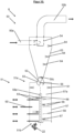
- the cyclone separator 50 has, in a manner known per se, a cyclone inlet 50a as well as an upper air outlet 50b and a lower material outlet 50c.
- the cyclone separator 50 is preferably a tangential separator.
- the cyclone separator 50 has a cyclone wall 53, which has a conical section in a manner known per se, and a dip tube 54.
- the cyclone separator 50 can have one or more addition points 64, at which further dry or liquid components can be added to the straw 22.
- the components are injected.
- the components can be preservatives, in particular sodium lauryl sulfate, or other additives, in particular hydrophilic agents.
- the straw 22 mixed with the hydrated lime is blown tangentially into the cyclone separator 50 together with the conveying air.
- the separation between air and straw 22 then takes place in a known manner. Due to the conical taper, the rotational speed of the straw 22 increases to such an extent that the straw 22 is thrown against the inside of the cyclone wall 53 by centrifugal force and is slowed down to such an extent that it is released from the flow and trickles down to the material outlet 50c.
- the air leaves the cyclone separator 50 through the dip tube 54.
- a mixer rotary valve 52 is arranged at the material outlet 50c. This serves to convey the straw 22 from the cyclone separator 50 into the mixing device 8.
- the mixer rotary valve 52 has a valve housing 55 and a rotary valve 56 arranged therein and a drive motor (not shown) for the rotary valve 56.
- the rotary valve 56 is connected to the drive motor so that it can rotate about a rotary valve axis, in particular a horizontal one, preferably at a speed of 200 to 950 rpm, preferably 350 to 500 rpm.
- the relatively high rotational speed ensures that the straw 22 does not clog the rotary valve 56. This is because straw is generally less free-flowing than other bulk materials.
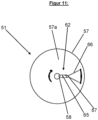
- the mixing device 8 ( Fig. 1 , 2 , 10 , 11 ) according to the invention has a multi-level mixer 51.
- the multi-stage mixer 51 has an upper mixer inlet end 51a and a lower mixer outlet end 51b and several, preferably 3 to 10, preferably 4 to 5, mixing chambers 51c arranged one above the other.
- the multi-level mixer 51 has a, in particular hollow cylindrical, mixer wall 57, a rotating or rotatably driven mixer shaft 58, a drive motor 100 for the mixer shaft 58, several fixed intermediate floor parts 59, several movable intermediate floor parts 60 as well as a binding agent addition device 61 and several mixer forks 62.
- the multi-level mixer 51 has one fixed intermediate floor part 59 and two movable intermediate floor parts 60 as well as at least one mixer fork 62, preferably two to four mixer forks 62, per level.
- the multi-level mixer 51 preferably has a mixer support frame 101.
- the mixer wall 57 surrounds a mixer interior or mixing chamber 57a.
- the mixer wall 57 is preferably also mounted on the mixer support frame 101.
- the mixer wall 57 is preferably formed from several strip-shaped wall segments 57b arranged next to one another in the circumferential direction. This increases the stability of the mixer wall 57.
- the mixer wall 57 also has a door 102.
- the binding agent addition device 61 serves to add a heat-curing binding agent mixture to the straw 22.
- the binding agent addition device 61 is preferably arranged in the uppermost mixing chamber 51c, preferably above the fixed intermediate floor part 59.
- the binder mixture is added in liquid form.
- the binder addition device 61 also preferably has a nozzle for injecting the binder mixture into the mixer interior 57a.
- the liquid binder mixture preferably contains water as a carrier substance.
- the binder mixture preferably comprises at least one protein and/or starch.
- the at least one protein can be of animal or vegetable origin.
- the binding agent mixture can also contain additives and/or additives.
- the mixer shaft 58 is arranged inside the mixer wall 57. It has a vertical mixer shaft rotation axis 58a. In addition, the mixer shaft 58 is connected to the drive motor 100 so that it can rotate about the mixer shaft rotation axis 58a.
- the drive motor 100 is preferably an asynchronous motor, in particular with a bevel gear or worm gear. In addition, the drive motor 100 is preferably arranged above the mixer wall 57 for reasons of space. In addition, the drive motor 100 is spatially separated from the emerging mixed material and is thus protected from damage by dust and aerosol.
- the mixer forks 62 each have a handle 65 and at least two prongs 66 protruding therefrom.
- the handle 65 is firmly attached to the mixer shaft 58 at one end and protrudes from the mixer shaft in the radial direction in relation to the mixer shaft rotation axis 58a.
- the prongs 66 are connected to the handle 65 at the other end.
- the prongs 66 of a mixer fork 62 are preferably arranged vertically one above the other and in alignment with one another.
- the tines 66 are mounted on the stem 65 so that they can be deflected about a vertical tine rotation axis 66a. In a non-deflected position, the tines 66 extend in a radial direction in relation to the mixer shaft rotation axis 58a. They are then arranged as an extension of the stem 65. And from the non-deflected position, the tines 66 can be deflected on both sides or in two directions against the force of at least one spring 67. In the deflected position, the at least one spring 67 thus causes a restoring force on the tines 66 into the non-deflected starting position.
- the mixer forks 62 do not have a handle 65, but the two tines 66 are connected to each other via the spring 67. And the spring 67 is firmly attached to the mixer shaft 58. In this case too, the tines 66 can be deflected on both sides or in two directions against the force of the spring 67.
- the spring-loaded tines 66 prevent material accumulations. It was determined during the invention that the straw 22 wetted with the binding agent mixture tends to clump. In the worst case, this leads to blockages and blockages in the mixer system.
- the spring-loaded tines 66 can easily break up material accumulations and prevent force peaks that would lead to damage in the system, as the tines 66 can give way.
- the fixed, horizontal intermediate floor parts 59 are preferably arranged adjacent to one another in the vertical direction and in alignment with one another.
- the fixed, horizontal intermediate floor parts 59 have a crescent shape.
- the fixed intermediate floor parts 59 with their circular-arc-shaped, convex floor peripheral wall 59a are connected to the inside of the mixer wall 57 or adjoin it.
- a concave, also circular-arc-shaped floor peripheral wall 59b is arranged at a distance from the mixer shaft 58. The fixed intermediate floor parts 59 are thus firmly connected to the mixer wall 57.
- the fixed, horizontal intermediate floor parts 59 also consist of metal, preferably of steel, preferably of stainless steel.
- the movable, horizontal intermediate floor parts 60 are also preferably arranged adjacent to one another in the vertical direction. They are also arranged in pairs.
- the movable, horizontal intermediate floor parts 60 each have a circular-arc-shaped, convex floor peripheral wall 60a, a straight floor peripheral wall 60b and an arc-shaped, convex, outer floor peripheral wall 60c.
- the diameter of the circular-arc-shaped, convex The bottom peripheral wall 60a corresponds to the diameter of the concave, circular arc-shaped bottom peripheral wall 59b of the fixed intermediate bottom parts 59.
- the straight bottom peripheral wall 60b also has a mixer shaft receiving recess 103.
- the movable intermediate floor parts 60 also consist of metal, preferably of steel, preferably of stainless steel.
- the movable, horizontal intermediate floor parts 60 can also be moved into and out of the mixer interior 57a, preferably in a direction perpendicular to the mixer shaft rotation axis 58a.
- the movable, horizontal intermediate floor parts 60 are each rotatable about a vertical intermediate floor axis of rotation or are hinged to bearing elements 104 of the mixer support frame 101. In addition, they each pass through a slot in the mixer wall 57. Furthermore, the movable, horizontal intermediate floor parts 60 are each connected to a pneumatic cylinder 105 that can be driven to rotate back and forth about the intermediate floor axis of rotation.
- the pneumatic cylinders 105 are preferably supported at one end on the mixer support frame 101 and at the other end on the respective movable intermediate floor part 60, in particular on its outer floor peripheral wall 60c.
- the two movable intermediate floor parts 60 of a mixing chamber 51c are moved towards or away from each other in a scissor-like manner when being moved in and out.
- the movable, horizontal intermediate floor parts 60 are also arranged in vertical alignment with one another.
- the two movable intermediate floor parts 60 of a mixing chamber 51c are each adjacent in the horizontal direction and aligned with a fixed intermediate floor part 59.
- the intermediate floor parts 59; 60 are arranged such that they each form a continuous, horizontal intermediate floor 63 when the two movable intermediate floor parts 60 are in their retracted position.
- the circular-arc-shaped, convex bottom peripheral walls 60a of the two movable intermediate bottom parts 60 lie in a form-fitting manner against the concave, circular-arc-shaped bottom peripheral wall 59b of the fixed intermediate bottom part 59.
- the two straight bottom peripheral walls 60b of the two movable intermediate bottom parts 60 also lie against one another.
- the mixer shaft 39 is arranged within the two mixer shaft receiving recesses 103.
- the straw 22 located on the intermediate floor 63 remains on the intermediate floor 63 in the respective mixing chamber 51c and is mixed by means of at least one mixing fork 62, preferably with two to four mixing forks 62.
- the intermediate floors 63 separate the individual mixing chambers 51c from each other.
- the two movable intermediate floor parts 60 are moved out of the mixer interior 57a.
- the straw 22 falls onto the intermediate floor 63 of the mixing chamber 51c located below. This process is repeated until the straw 22 has arrived at the mixer outlet end 51b.
- the mixed straw 22 then falls out of the multi-level mixer 51 and in particular into another conveyor channel 9, through which the straw 22 is conveyed to the insulation board pressing device 10.
- the opening process and the closing process preferably each last 2 to 4 s and the movable intermediate floors 60 preferably remain in their open position for 8 to 12 s.
- the straw 22 wetted with the binding agent mixture tends to clump and become blocked during mixing.
- the advantage of the multi-level mixer 51 is that the mass flow of the straw 22 is broken down by the mixing chambers 51c. Nevertheless, the mixing process is essentially a continuous process.
- the mixing chamber is divided into individual mixing chambers 51c located one above the other.
- the further conveyance of the straw 22 is regulated by means of the movable intermediate floor parts 60 by regulating the opening times of the intermediate floor parts 60 accordingly. This prevents the individual mixing chambers 51c from becoming overfilled. With this forced breaking down of the mass flow and equally forced residence time of the mixed material in the individual mixing chambers 51c, a high mixing quality is achieved.
- mixed straw 22 is conveyed through the conveyor channel 9 to the insulation board pressing device 10.
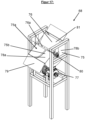
- the insulation board pressing device 10 ( Fig. 1 , 14-16 ) preferably has a throwing device 68, a conveyor belt 69, a compaction and binding agent activation device 70, a drying device 72 and a cutting device 73.
- the continuous insulation board pressing device 10 preferably has a base frame 74.
- the throwing device 68 serves to throw or hurl the straw 22 arriving from the conveyor channel 9 onto the conveyor belt 69.
- a channel outlet end of the conveyor channel 9 is arranged above the throwing device 68 so that the straw 22 falls from the conveyor channel 9 into the throwing device 68.
- the throwing device 68 ( Fig. 15-17 ) has a collecting container 75, a blade 76 rotating about a blade rotation axis 76a and a drive motor 77 for driving the blade 76.
- the collecting container 75 is mounted in particular on the base frame 74.
- the collecting container 75 has a curved container wall 78a and two adjoining container side walls 78b.
- the two container side walls 78b are arranged opposite one another as seen in the direction of the blade rotation axis 76a.
- the curved container wall 78a is preferably designed to be rotationally symmetrical to the blade rotation axis 76a.
- the curved container wall 78a is thus designed as a cylinder jacket section.
- the collecting container 75 is open at the top and has a container opening 75a.
- the collecting container 75 is thus designed as a collecting tray.
- the two container side walls 78b and the curved container wall 78a surround a container interior 75b.
- the throwing device 68 also has two protective plates 79, each of which adjoins an end edge of the curved container wall 78a and protrudes outwards from it.
- the protective plates 79 serve in particular to prevent straw from falling into the drive motor 77.
- the blade 76 has a preferably hollow cylindrical blade shaft 80 and a single blade 81. However, several blades 81 can also be present, but a single blade is preferred.
- the blade shaft 80 is designed to be rotationally symmetrical to the blade rotation axis 76a. The blade 81 protrudes from the blade shaft 80 in the radial direction in relation to the blade rotation axis 76a.
- the blade 76 is mounted in the area of the container opening 75a by means of the blade shaft 80 so that it can rotate about the blade rotation axis 76a.
- the blade 76 is connected to the drive motor 77 so that it can rotate about the blade rotation axis 76a, e.g. via a belt drive (not shown).
- the drive motor 77 is preferably a three-phase motor (asynchronous motor) and/or a servo motor.
- the blade 76 rotates partly inside the collecting container 75 and partly outside the collecting container 75. It is dimensioned such that it is slightly spaced from the curved container wall 78a and the two container side walls 78b. By means of the blade 76, the straw 22 located in the container interior 75b is thus removed.
- the conveyor belt 69 moves in a horizontal conveying direction 82.
- the conveying direction 82 is perpendicular to the blade rotation axis 76a.
- the conveyor belt 69 is mounted on the base frame 74.
- the two side walls lie opposite each other in a direction parallel to the blade rotation axis 76a. They also extend to the throwing device 68 and shield it laterally.
- the straw 22 falls from the conveyor channel 9 down into the throwing device 68. In particular, it falls into the collecting container 75 and onto the rotating shovel blade 81. As a result, the straw 22 is caught by the shovel blade 81 and thrown parabolically onto the conveyor belt 69. There it is deposited in particular according to the Gaussian normal distribution. This results in a uniformly high, continuous or endless layer of straw on the conveyor belt 69. This homogenization process ensures a uniform density distribution of the straw layer in the conveying direction 82 and the individual straw portions that come from the mixing device 8 are converted into a uniform mass flow.
- the constant density distribution transverse to the conveying direction 82 is achieved in particular via the two side walls 83.
- the straws that would otherwise be deposited in the outer edge area are caught by the side walls 83 and "added" to the flatter edge area of the mixed material, so that a homogeneous density distribution is also achieved across the cross-section.
- the continuous layer of straw located on the conveyor belt 69 is then transported by means of the conveyor belt 69 into the compaction and activation device 70.
- the compaction and activation device 70 has a rotating press belt 85, which is arranged above the conveyor belt 69. Viewed in the conveying direction 82, the distance of the press belt 85 from the conveyor belt 69 initially decreases and then remains constant. A funnel that tapers in the conveying direction 82 is thus formed between the press belt 85 and the conveyor belt 69, in which the straw layer is increasingly compacted into an endless straw strand or an endless straw web. In addition, the straw layer is drawn into the funnel by the conveyor belt 69 and the press belt 85.
- the binder mixture is thermally activated.
- the straw strand is exposed to steam.
- the steam is applied alternately from above and above in the conveying direction 82. If necessary, negative pressure is also applied from the vertically opposite side so that the steam is drawn through the straw strand. This results in the straw strand being exposed to steam evenly and the binder mixture being thermally activated evenly across the entire cross-section of the straw strand.
- the conveyor belt 69 and the press belt 85 are also preferably designed as perforated belts so that the steam can flow through the belts 69;85 into the straw strand.
- the conveyor belt 69 and the press belt 85 are preferably made of plastic, preferably polypropylene. This prevents the binding agent mixture from adhering to the respective belt 69;85.
- the conveyor belt 69 and the press belt 85 can also be made of stainless steel and be designed as a perforated belt. This is advantageous for higher panel densities.
- the compacted straw strand is conveyed into the drying device 72 by means of the conveyor belt 69.
- Drying is particularly advantageous because the straw strand is relatively moist due to the condensed water vapor that activates the binding agent. This leads to a lower strength and binding ability of the binding agent. In order to achieve sufficient strength for further processing, especially for cutting, in a reasonable amount of time, the straw strand is dried.
- the drying device 72 is preferably designed as a drying channel.
- the straw strand is exposed to hot air for drying in alternating directions, preferably first from above, then from below and then again from above, as seen in the conveying direction 82. This enables uniform drying across the cross-section of the straw strand to be achieved.
- the hot air provided preferably has a temperature of 100 to 120 °C, preferably 105 to 115 °C.
- the hot air is preferably extracted in order to further improve the flow of hot air through the straw strand in a vertical direction.
- the drying device 72 also preferably has a plurality of rotating drive belts 86 arranged above the conveyor belt 69, which ensure uniform transport of the straw strand and keep it in shape.
- the dried straw strand is conveyed to the cutting device 73 by means of the conveyor belt 69.
- the cutting device 73 serves to cut the endless straw strand into individual straw insulation panels 12.
- the cutting device 73 preferably has a rotating circular saw 87 or a rotating band saw.
- the straw insulation boards 12 produced have a low density and therefore good thermal insulation properties.
- the straw insulation boards 12 have a thermal conductivity ⁇ D of 0.038 to 0.049 W/m K, preferably of 0.039 to 0.045 W/m K, according to DIN EN 13171:2015-04, paragraph 4.2.1.
- the straw insulation boards 12 preferably have a bulk density of 100 to 150 kg/m 3 , preferably 105 to 120 kg/m 3 , according to DIN EN 1602:2013-05.
- the straw insulation boards 12 are used as plasterboards or load distribution boards or impact sound boards or merely for thermal insulation, in particular in a thermal insulation composite system.
- the device 1 according to the invention serves according to a further embodiment of the invention ( Fig. 2 , 18 , 19 ) for the production of dense straw panels 13.
- the device 1 according to the further embodiment differs from the device 1 according to the first embodiment only in that the plate pressing device 14 is designed differently since a higher compaction is necessary.
- binder mixture is preferably added.
- the pressing device 14 has a receiving device 87, a press 88 and preferably a trimming device 89 arranged downstream of one another in the conveying direction 82.
- the receiving device 87 has a drivable receiving conveyor belt 90, two boundary walls 91 arranged spaced apart from one another in the horizontal direction, and a distribution device 92.
- the boundary walls 91 are adjacent to one another in a direction perpendicular to the conveying direction 82 and are arranged on both sides of the receiving conveyor belt 90. They thus limit the receiving conveyor belt 90 laterally.
- the straw 22 coming from the mixing device 8 and mixed with the binding agent mixture is now applied to the receiving conveyor belt 90. This is done, for example, by arranging the receiving conveyor belt 90 directly below the mixing device 8 and allowing the straw 22 to fall directly from the mixing device 8 onto the receiving conveyor belt 90.
- the straw 22 can also be applied to the receiving conveyor belt 90 in another way, e.g. by means of a conveying means, e.g. a conveyor belt or a conveyor channel.
- a conveying means e.g. a conveyor belt or a conveyor channel.
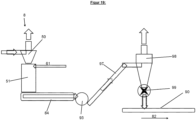
- Figure 19 shows preferred further conveying possibilities.
- the device 1 has a further vibrating trough 84 after the mixing device 8, a radial fan 93 connected to it, a conveying channel 97 connected to it, and a cyclone separator 98 connected to it, which preferably has a rotary valve 99 at the lower end.
- the vibrating trough 84 is designed in particular in a similar way to the first vibrating trough 5.
- the radial fan 93 and the conveying channel 97 have the advantage that the mixing quality is maintained by the conveying process of the air conveyance.
- the cyclone separator 98 serves to separate the conveying air.
- the straw 22 is also applied by the cyclone separator 98 in a meandering shape, preferably in a cross connection, to the receiving conveyor belt 90.
- the cyclone separator 98 can preferably be moved on a portal in two mutually perpendicular horizontal directions, with one direction being parallel to the conveying direction 82.
- the cyclone separator 98 can also only be moved perpendicular to the conveying direction 82 and the receiving conveyor belt 90 moves in the conveying direction 82 when applying the straw 22.
- the distribution device 92 By means of the distribution device 92, the straw 22 is then evenly distributed on the receiving conveyor belt 90 to form a straw cake 71.
- the distribution device 92 preferably has a portal with distribution arms that can be moved back and forth in two mutually perpendicular, horizontal directions.
- the receiving conveyor belt 90 is driven and the straw cake 71 is conveyed by means of the receiving conveyor belt 90 in the conveying direction 82 into the press 88.
- the press 88 has a lower, rotating press belt, preferably with a separating film, as well as two heatable press plates 94 arranged one above the other and preferably a separating film arranged between the upper press plate 94 and the straw cake 71.
- the press belt runs around the lower press plate 94.
- the press belt serves, on the one hand, to convey the straw cake 71 into the press 88, for which purpose it is driven until the straw cake 71 has reached its predetermined position between the two press plates 94.
- the two parallel press plates 94 are now pressed against one another, preferably hydraulically.
- the two press surfaces 94a of the two press plates 94 are preferably kept at a distance by spacer strips on the edge of the press surfaces 94a.
- the press belt is not driven and is arranged between the straw cake 71 and the lower pressing surface 94a. It thus forms a temperature-stable separating layer between the straw cake 71, especially the binding agent, and the lower heated pressing plate 94.
- the press belt After pressing, the press belt also serves to convey the straw plate 13 out of the press 88 in the conveying direction 82 into the trimming device 89.
- the edges of the straw plate 13 are trimmed, preferably by means of a circular saw 95 that can be moved back and forth.
- the trimming device 89 also preferably has a trimming device conveyor belt 96 for conveying the straw plate 13.
- the produced straw panels 13 are then removed from the trimming device 89.
- the heat for activating the binding agent is introduced into the straw layer primarily via the pressing surfaces 94a, which are preferably heated by means of thermal oil.
- the pressing surfaces 94a preferably have a temperature of 100 to 120 °C, preferably 105 to 115 °C.
- the straw panels 13 produced Due to the high temperature, the introduction of heat through contact heat and the lower binder content, the straw panels 13 produced achieve very good surface strength and dimensional stability when they leave the press 88. In this case, there is no need for subsequent drying to maintain the shape, as is preferably the case with the straw insulation panels 12.
- the residual moisture essentially adjusts to the ambient air humidity within a day.
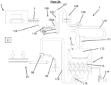
- Figure 20 shows a device 1 according to the most preferred embodiment of the invention.
- the device 1 according to the most preferred embodiment of the invention also serves to produce dense straw panels 13 or straw insulation panels 12.
- the device 1 comprises, arranged one after the other, the straw bale breaking device 2, the conveying channel 3, a homogenizing screw 106, a stone separator 107, a straw witch 108, a radial blower 109, a conveying section 110, preferably a conveying channel, a cyclone separator 111, a weighing device 112, a screw mixer 113 according to the invention, a binding agent addition device 114, a radial fan 115, a conveying section 116, preferably a conveying channel, preferably the distribution device 92, as well as the pressing device 14 and the control device 11.
- the device 1 is used exclusively for producing straw insulation boards 12, it has the insulation board pressing device 10 (not shown) instead of the pressing device 14.
- the homogenization screw 106 ( Fig. 20 ) is connected to the conveyor channel 3.
- the conveyor channel does not have a milling drum 24.
- the homogenization screw 106 has a collecting container 118 and a homogenization conveyor screw 119.
- the straw is conveyed into the collecting container 118 by the discharge conveyor screw 20 of the straw bale breaking device 2.
- the collecting container 118 preferably has mechanical fill level sensors that detect the fill level.
- the conveying capacity of the straw bale breaking device 2 is preferably controlled by means of the control device 11 on the basis of the signals from the fill level sensors.
- the homogenization screw 106 achieves a uniform straw flow that is easily conveyed by air.
- the homogenization conveyor screw 119 draws a homogeneous straw mass flow from the collecting container 118 and conveys the straw 22 into the stone separator 107.
- the stone separator 107 ( Fig. 20 ) is preferably a riser pipe sifter.
- the stone separator 107 preferably has an upright, preferably vertical, separator pipe 120 which is open at the bottom and is suspended.
- the separator pipe 120 also has a lateral opening 120a at the bottom into which the straw 22 is fed by the homogenization conveyor screw 119.
- a lower opening 120b of the separator pipe 120 floats above a cone 121 and is spaced apart from it, the cone 121 and the separator pipe 120 being coaxial with one another. An air gap is present between the cone 121 and the separator pipe 120.
- the conveying air required for transporting the straw 22 through the stone separator 107 is sucked out by the blower 115 connected downstream of the stone separator 107.
- the size of the air gap can be used to change both the air quantity and the flow speed of the conveying air.
- the conveying air pulls the conveyed straw 22 upwards. Other particles that have a different mass or density than the straw cannot be transported upwards by the conveying air flow against gravity and fall downwards out of the separator pipe 120.
- the straw 22 can be separated from heavier particles, e.g. stones and/or dirt and/or grains and/or metal, in a simple and reliable manner. This protects the individual devices of the device 1 according to the invention in the further production process and increases the quality of the panels 12; 13 to be produced.
- heavier particles e.g. stones and/or dirt and/or grains and/or metal
- the stone separator 107 can of course also be present in a particularly advantageous manner in the previously described devices 1.
- the straw 22 is fed from the stone separator 107 into the straw cutter 108.
- the straw cutter 108 is known per se and is used to chop the straw stalks to a predetermined length, preferably to a length of 10 mm to 60 mm, preferably 20 mm to 40 mm.
- the straw cutter has rotating blades in a manner known per se. At least some of the straw stalks of the straw 22 are also spliced.
- the straw witch 108 makes the straw 22 more homogeneous and a more precisely defined raw material. This improves the quality of the panels, regardless of the quality of the straw cut delivered.
- the cut straw 22 also has better air conveying capacity and better mixability, as it is more pourable.
- Another particular advantage is that the adhesion of the binding agent to the straws is improved, as the inside of the straws can also be wetted by spreading them out. The wettable surface is therefore increased.
- the increased number of contact points during bonding also improves the statics of the panels.
- the plates 12; 13 have a more optically homogeneous appearance and further processing, in particular sawing and/or milling, is facilitated.
- the straw witch 108 can of course also be present in a particularly advantageous manner in the previously described devices 1.
- the shredded straw 22 is conveyed to the cyclone separator 111 by means of the conveying section 116.
- the cyclone separator 111 serves to separate the conveying air from the straw 22 and to fill the weighing device 112.
- the weighing device 112 ( Fig. 20 ) is used for weighing the straw 22 in portions before the subsequent mixing process.
- the weighing device 112 has a trough 122 and a frame 123.
- the trough 122 is suspended from the frame 123 by means of load cells 124, in particular bending beam cells, which are connected to the control device 11.
- the tub 122 has two tub end walls 122a, two tub side walls 122b, a tub lid 122c and a tub bottom wall 122d.
- the tub bottom wall 122d is preferably designed in two parts and has two bottom flaps 125, which are pivotably mounted on each of the tub side walls 122b.
- the two tub bottom parts 125 can be pivoted in such a way that they can pivot or fold away to the side and a tub bottom opening is formed between them through which the straw 22 can fall out of the tub 122.
- the tub 122 also has corresponding, preferably electric or pneumatic, drive means, preferably pneumatic linear cylinders. Electric and pneumatic pivot drives can also be used.
- the tub lid 122c also has a filling opening 126 through which the straw 22 is filled into the tub 122.
- the weighing device 112 has a shut-off slide or closing slide 127.
- the closing slide 127 can be moved back and forth parallel to the tub cover 122c from a position that closes the filling opening 126 to a position that exposes the filling opening 126.
- the weighing device 112 also has corresponding, preferably electric or pneumatic, drive means, preferably pneumatic linear cylinders.
- the closing slide 127 is mounted on the frame 123 independently of the tub 122.
- the closing slide 127 has a slide base plate 127a, two slide side walls 127b and a slide rear wall 127c.
- the lime hydrate is also added in the weighing device 112.
- the tank lid 122c has a lime inlet opening.
- the lime hydrate supply device 6 described above is arranged above the lime inlet opening.
- the weighing device 112 also has two boundary walls 128 that extend away from the tub cover 122c and delimit the filling opening 126.
- the two boundary walls 128 are parallel to the slider rear wall 127c.
- the two boundary walls 128 are also mounted on the frame 123 independently of the tub 122.
- the slide base plate 127a In the release position, the slide base plate 127a is not vertically aligned with the filling opening 126. As soon as the desired filling quantity is reached, the outlet opening of the cyclone separator 111 is closed by moving the closing slide 127 into the closing position.
- the slide base plate 127a In the closing position, the slide base plate 127a is arranged vertically aligned with the filling opening 126 and closes it off.
- the two boundary walls 128 and the two slide side walls 127b together with the slide base plate 127a form an upwardly open collecting container 129 for the straw 22 that trickles out of the cyclone separator 111 after the filling opening 126 is closed. This ensures that the trough 122 is filled with a precisely defined amount of straw. This is preferably 2.0 to 10.0 kg, more preferably 2.1 to 6.0 kg.
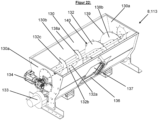
- the screw mixer 113 has a mixing trough 130 for receiving the material to be mixed, at least two mixing screws 131; 132 arranged one above the other and two mixing screw drive motors 133; 134.
- Both mixing screws 131; 132 are each driven individually by a mixing screw drive motor 133; 134, in particular an electric one.
- a mixing screw drive motor 133; 134 in particular an electric one.
- the mixer trough 130 has two opposing trough front walls 130a as well as two trough side walls 130b and a trough bottom wall.
- the two supporting side walls 130b run towards each other in the direction of the trough bottom wall, so that the mixer trough 130 tapers downwards.
- the mixer trough 130 is sealed dust-tight by the weighing device 112.
- a trough cover is therefore preferably not present.
- the screw mixer 113 also has at least two mixing screws 131; 132 arranged one above the other.
- the two mixing screws 131; 132 each have a screw rotation axis 131a; 132a, a screw shaft 131b; 132b and a screw blade or a screw thread 131c; 132c.
- the screw blade 131c of the first, in particular lower, mixing screw 131 is formed from two blade sections 135a;b that run in opposite directions.
- the two blade sections 135a;b have an opposing pitch such that the lower mixing screw 131 conveys the material to be mixed towards the middle of the mixer trough 130 or away from the two trough front walls 130a.
- the mixer trough 130 has corresponding, preferably electric or pneumatic, drive means, preferably pneumatic linear cylinders.
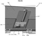
- the first, in particular lower, mixing screw 131 has a radially arranged discharge plate 141 in the middle of the mixing screw 131, where the two counter-rotating wing sections 135a;b meet.
- the screw wing 132c of the second, in particular upper, mixing screw 132 is also formed from two mutually oppositely rotating wing sections 138a;b.
- the two wing sections 138a;b have such an oppositely rotating pitch that the upper mixing screw 132 Material is conveyed away from the center of the mixing trough 130 or towards the two trough end walls 130a.
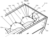
- the second, in particular upper, mixing screw 132 has a plurality of teeth 139 which protrude outwards from the screw wing 132c in the radial direction in relation to the screw rotation axis 132a. In particular, they protrude from an outer edge 140 of the screw wing 132c.
- the prongs 139 serve to break up any conglomerates or accumulations during the mixing process and to loosen the mixture in general.
- the teeth 139 also have two serrated edges 139a;b that merge into one another and a serrated tip 139c, wherein the serrated edges 139a;b preferably form an obtuse angle with one another.
- the teeth 139 are spaced apart from one another by 20° to 90°, preferably 30° to 45°, in a circumferential direction in relation to the screw rotation axis 132a.
- the prongs 139 preferably have a height of 20 mm to 60 mm, preferably 30 mm to 40 mm.
- the height of the prongs corresponds to the distance of the prong tip 139c from the outer edge 140 of the wing.
- the binding agent addition device 114 serves to add the liquid binding agent mixture described above to the straw 22.
- the mixer trough 130 has a plurality of radially distributed around the upper mixing screw 132. Binder inlets. This can prevent binder nests and sticking.
- the binder inlets are supplied with the binder mixture by the binder addition device 114.
- the binder mixture is preferably filled in without nozzles.
- binding agent is preferably only started when the mixer trough 130 is filled with at least 20 mass-%, preferably at least 30 mass-% of the straw quantity.
- the trough outlet opening 136 is opened and the lower mixing screw 131 conveys the finished mixed material out of the screw mixer 113 in a radial direction with the discharge plate 141. This happens gradually and evenly.
- the discharge speed can be determined via the speed of the mixing screws 131; 132. This even discharge forms the basis for further conveying of the mixed material with conveying air.
- straw 22 mixed with binding agent is conveyed to the distribution device 92 by means of the conveyor line 116.
- the dense straw panels 13 are used as carrier panels, preferably as plaster carrier panels or as heating carrier panels, or as acoustic panels.
- the dense straw panels 13 preferably have a density of 200 to 520 kg/m 3 , preferably 210 to 240 kg/m 3 , particularly preferably 210 to 230 kg/m 3 , according to DIN EN 1602:2013-05.
- the dense straw panels 13 also have a compressive strength of 3.0 to 4.0 N/mm 2 , preferably 3.3 to 3.8 N/mm 2 , according to DIN EN ISO 29469:2023-02.
- the advantage of the device 1 according to the invention is that it ensures the production of straw panels 12;13 with excellent and uniform quality. This is achieved in particular by a uniform mixing of the straw 22 achieved with the liquid binder mixture.
- the mixer forks 62 can easily break up these accumulations of material thanks to the spring-loaded tines 66 and force peaks that can lead to damage are avoided.
- the further conveyance of the straw 22 is regulated by the inventive division of the mixing space 57a into the individual vertically stacked mixing chambers 51c and by means of the retractable and extendable intermediate floor parts 60. This prevents the individual mixing chambers 51c from being overfilled. And with this forced division of the straw mass flow and equally forced residence time of the straw 22 in the individual mixing chambers 51c, a high mixing quality is achieved.
- the straw 22 is separated from the transport air. This ensures that the multi-level mixer 51 only works with straw lengths that are within the stable operating limits of the multi-level mixer 51.
- a uniform application of the straw 22 mixed with the binding agent mixture onto the conveyor belt 69 of the pressing device 10 is important for the properties of the subsequent straw insulation panels 12.
- the laying of the individual straws has an influence on the density distribution as well as on the mechanical properties of the straw insulation panel 12.
- the problem here is that the straw-binding agent mixture is neither pourable nor free-flowing. It is therefore advantageous if it is actively broken down and laid down again in order to avoid local density differences in the straw insulation panel 12.
- a loose, undirected laying of the straws is advantageous, so that the subsequent Compaction ensures the best possible interlocking of the straws with each other. Separating layers caused by aligned straws, which have a negative effect on the mechanical properties of the straw insulation boards 12, can thus be avoided.
- alignment or layering of the straws should be avoided, as this can lead to predetermined breaking points in the straw insulation board.
- the optimal application of the straw 22 onto the conveyor belt 69 is achieved by means of the throwing device 68.
- the rotating scoop 76 simultaneously breaks up nests and clumps in the straw-binder mixture and throws the straw-binder mixture onto the conveyor belt 69.
- the straw-binder mixture is thrown in a parabolic shape onto the moving conveyor belt 69, where it is deposited according to a Gaussian normal distribution. This results in a uniformly high layer of straw on the conveyor belt 69.
- This homogenization process ensures a uniform density distribution of the straw layer in the conveying direction 82 and the individual straw portions that come from the mixing device 8 are converted into a uniform mass flow.
- the phase transition of the steam to the liquid phase also creates local negative pressures, which allow more steam to flow in and thus ensure that the entire straw layer is heated completely and without any defects. This reliably activates the binding agent in every area.
- the straws also become soft for a short time and the springback forces decrease. This reversible change in the straw 22 enables the pressed straw layer strand to be shaped and demolded more quickly without the long calibration steps that would otherwise be necessary until the binding agent reaches its final strength after drying.
- the hydrated lime is very advantageous to add separately from the binder. Since the hydrated lime is not added mixed with the binder, it is at least partially free of binder and has more free surface area. This makes it more reactive. Adding hydrated lime to the liquid binder mixture would also thicken the binder mixture.
- Another advantage is that the production takes place essentially in earth-moist form.
- the straw 22 is only wetted with the binding agent and the straws are only connected to one another at the contact points.
- the device 1 it is of course also possible for the device 1 to have several plate pressing devices 10; 14 operated in parallel.
- the screw mixer is particularly advantageous, as described above, and is the preferred mixing device.
- the rapid movement of the mixture through the mixing screws in the screw mixer also causes air to be swirled into the mixture.
- the teeth on the upper mixing screw in particular contribute to This makes a significant contribution to this.
- the straw which otherwise tends to form conglomerates and clumps, changes its properties and behaves like a fluid.
- the solid auger construction is insensitive to blockages and damage caused by compacted fiber-binder nests. Only two moving parts are involved in the mixing process - the two mixing augers.
- the easily accessible but closed design of the mixing chamber and the external motors mean that the auger mixer is very easy to maintain and at the same time low-maintenance.
- the encapsulated mixing chamber is sealed and reduces dust emissions to a minimum.
- the stack mixer 51 and the screw mixer 113 can be interchanged.
- stone separator 107 and/or the straw witch 108 can of course also be integrated into the devices 1 according to Figures 1 and 2 Both the stone separator 107 and the straw separator 108 must always be arranged in front of the mixing device 8.
- the weighing device 4;112 is arranged just before the respective mixer 51;113, preferably directly in front of it. It is then also in the embodiments according to Figure 1 and 2 preferably arranged between the cyclone separator 50 and the multi-stage mixer 51. This allows for particularly precise dosing and precise mixture of straw, binder mixture and hydrated lime is ensured.
- the addition of hydrated lime in the weighing device 112, i.e. after the air conveying, is also advantageous for all embodiments, since otherwise there is a risk that the hydrated lime will separate from the straw 22 again due to the air conveying.
- the hydrated lime supply device 6 can also be used very advantageously in the production of other fiberboards or chipboards for adding hydrated lime to the fibers, in particular the straw, or the chips.
Landscapes
- Engineering & Computer Science (AREA)
- Mechanical Engineering (AREA)
- Chemical & Material Sciences (AREA)
- Structural Engineering (AREA)
- Ceramic Engineering (AREA)
- Chemical Kinetics & Catalysis (AREA)
- Manufacturing & Machinery (AREA)
- Dispersion Chemistry (AREA)
- Life Sciences & Earth Sciences (AREA)
- Wood Science & Technology (AREA)
- Processing Of Solid Wastes (AREA)
- On-Site Construction Work That Accompanies The Preparation And Application Of Concrete (AREA)
- Fertilizers (AREA)
- Processing And Handling Of Plastics And Other Materials For Molding In General (AREA)
Abstract
Description
- Die vorliegende Erfindung betrifft ein Verfahren und Vorrichtungen zur Herstellung von Strohplatten sowie eine Kalkhydrat-Zuführeinrichtung dafür.
- Die
EP 2 799 639 A1 offenbart eine Dämmplatte zur Dämmung einer Gebäudefassade, wobei die Dämmplatte aus Stroh, welches mittels eines Klebstoffes zusammengehalten wird, aufgebaut ist. Bei dem Klebstoff kann es sich um Leim, insbesondere Pflanzenleim, oder Stärkekleber handeln. Die Herstellung der Dämmplatte erfolgt durch Vermischen von, vorzugsweise gehäckseltem Stroh mit dem Klebstoff, leichtes Verpressen der Stroh-Klebstoff-Mischung zu einer Dämmplatte und Stehenlassen der so hergestellten Dämmplatte zum Austrocknen derselben. Zum Austrocknen wird die Dämmplatte vorzugsweise erwärmt, insbesondere auf eine Temperatur von ca. 25 -50 °C. - Aus der
DE 198 10 862 A1 geht eine Dämmplatte aus Stroh hervor, bei der die Faserlänge des Strohs maximal 150 mm ist, das Stroh faserig zerkleinert ist und die geschlossene Halmstruktur durch Längsspleißung zerstört ist, die Strohfasern mit einem biologisch abbaubaren Bindemittel homogen gemischt sind, das Gemisch aus Strohfasern und Bindemittel geringfügig mechanisch zu Plattenmaterial verdichtet ist, die Mindestdicke der Platte 30 mm beträgt und die Rohdichte 40 bis 100 kg/m3 beträgt. Die Platte ist zudem beidseitig mit einer flexiblen gitterartigen Naturfaser-Beschichtung versehen. Vorzugsweise weisen die Strohfasern weitgehend eine Länge von mindestens 2 mm oder mehr auf. Die Herstellung der Dämmplatte erfolgt durch faseriges Zerkleinern des Strohs und Aufspleißen des Strohs in der Länge zu einer Fraktion mit Faserlängen bis maximal 150 mm. Die Faserfraktion wird anschließend homogen mit einem biologisch abbaubaren, Wasser im Überschuss enthaltenden Bindemittel gemischt und die Mischung auf eine mit Bindemittel getränkte Bahn des Beschichtungsmaterials unter geringfügiger Verformung fortlaufend aufgetragen. Das Mischen der Faserfraktion mit Bindemittel und Flammschutzmittel erfolgt vorzugsweise in einer Mischvorrichtung. Die homogene Mischung wird dann von einem Förderband in ein Mischsilo gefördert, das am unteren Ende eine Austragwalze aufweist und oberhalb eines Plattenförderbandes angeordnet ist, auf dem die getränkte Bahn des Beschichtungsmaterials angeordnet ist. - Auf die so entstehende Dämmstoffbahn wird eine obere, mit Bindemittel getränkte Beschichtungsbahn aufgelegt und die so entstandene Dämmstoffbahn wird durch eine Heizzone gefördert und getrocknet und gegebenenfalls vulkanisiert. Dies erfolgt vorzugsweise im Heißluft-Durchströmverfahren mit einer Heißlufttemperatur von etwa 100°C. Beim Trocknen wird das Bindemittel getrocknet bzw. vulkanisiert, wobei der sich bildende Wasserdampf als Wärmeträger dient und die Vulkanisation fördert. Die getrocknete Bahn wird anschließend zu Platten geschnitten.
- Aufgabe der vorliegenden Erfindung ist die Bereitstellung eines kostengünstigen Verfahrens und einer Vorrichtung zur Herstellung von Strohplatten, das bzw. die eine gleichmäßige und gute Qualität der hergestellten Strohplatten gewährleistet.
- Weitere Aufgabe ist die Bereitstellung einer Kalkhydrat-Zuführeinrichtung dafür zur genauen Zudosierung von Kalkhydrat zum Stroh.
- Diese Aufgaben werden durch eine Kalkhydrat-Zuführeinrichtung gemäß Anspruch 1, eine Vorrichtung gemäß Anspruch 4 und 19 und ein Verfahren gemäß Anspruch 22 gelöst. Vorteilhafte Weiterbildungen der Erfindung sind in den sich anschließenden Unteransprüchen gekennzeichnet.
- Im Folgenden wird die Erfindung anhand einer Zeichnung beispielhaft näher erläutert. Es zeigen:
- Figur 1:
- Eine vereinfachte, schematische Darstellung der erfindungsgemäßen Vorrichtung gemäß einer ersten Ausführungsform der Erfindung
- Figur 2:
- Eine vereinfachte, schematische Darstellung der erfindungsgemäßen Vorrichtung gemäß einer weiteren Ausführungsform der Erfindung
- Figur 3:
- Eine vereinfachte, schematische seitliche Darstellung einer Strohballenauflösungseinrichtung
- Figur 4:
- Eine vereinfachte, schematische seitliche Darstellung einer Wiegeeinrichtung
- Figur 5:
- Eine perspektivische Ansicht der Wiegeeinrichtung
- Figur 6:
- Eine vereinfachte, schematische seitliche Darstellung einer Rüttelrinne mit Kalk-Zuführeinrichtung
- Figur 7:
- Eine perspektivische Ansicht der Kalkhydrat-Zuführeinrichtung
- Figur 8:
- Einen Längsschnitt der Kalkhydrat-Zuführeinrichtung
- Figur 9:
- Eine perspektivische, halbgeschnittene Ansicht der Kalkhydrat-Zuführeinrichtung
- Figur 10:
- Einen vereinfachten, schematischen Längsschnitt durch eine erfindungsgemäße Mischeinrichtung und einen Zyklonabscheider
- Figur 11:
- Einen vereinfachten, schematischen Querschnitt durch einen Etagenmischer der Mischeinrichtung ohne Zwischenboden
- Figur 12:
- Einen weiteren Querschnitt durch den Etagenmischer ohne Mischerwelle
- Figur 13:
- Eine Seitenansicht des Etagenmischers
- Figur 14:
- Eine vereinfachte, schematische seitliche Darstellung der Mischeinrichtung und einer Dämmplattenpresseinrichtung ohne eine Schneideinrichtung
- Figur 15:
- Eine perspektivische Darstellung eines Bereichs der Dämmplattenpresseinrichtung
- Figur 16:
- Eine weitere perspektivische Darstellung eines Bereichs der Dämmplattenpresseinrichtung ohne eine Seitenwand
- Figur 17:
- Eine perspektivische Darstellung einer Wurfeinrichtung der Dämmplattenpresseinrichtung
- Figur 18:
- Eine vereinfachte, schematische seitliche Darstellung einer Plattenpresseinrichtung gemäß der weiteren Ausführungsform der erfindungsgemäßen Vorrichtung
- Figur 19:
- Stark vereinfacht und schematisch eine Darstellung der erfindungsgemäßen Vorrichtung gemäß der weiteren Ausführungsform der Erfindung mit weiteren Fördermitteln zwischen der Mischeinrichtung und der Plattenpresseinrichtung
- Figur 20:
- Eine vereinfachte, schematische Darstellung der erfindungsgemäßen Vorrichtung gemäß einer weiteren Ausführungsform der Erfindung
- Figur 21:
- Eine perspektivische Ansicht einer weiteren Wiegeeinrichtung, Verschließschieber in halb geschlossener Stellung
- Figur 22:
- Eine perspektivische Ansicht eines erfindungsgemäßen Schneckenmischers
- Figur 23:
- Eine Schnittansicht des erfindungsgemäßen Schneckenmischers
- Figur 24:
- Einen Teil einer Draufsicht auf den erfindungsgemäßen Schneckenmischer
- Figur 25:
- Einen Teil einer Seitenansicht des erfindungsgemäßen Schneckenmischers
- Die erfindungsgemäße Vorrichtung 1 dient zur Herstellung von Strohplatten 12;13. Die herzustellenden Strohplatten 12;13 sind vorzugsweise einschichtig bzw. monolithisch aufgebaut und bestehen aus Stroh, welches mit einer erhärteten Bindemittelmatrix zusammengehalten wird. Die Bindemittelmatrix verbindet die einzelnen Strohhalme miteinander.
- Gemäß einer ersten Ausführungsform der Erfindung (
Fig. 1 ) dient die erfindungsgemäße Vorrichtung 1 zur Herstellung von dämmenden Strohplatten 12 bzw. Strohdämmplatten 12 und weist einander nachgeordnet eine Strohballenauflösungseinrichtung 2, einen Förderkanal 3, eine Wiegeeinrichtung 4, eine Rüttelrinne 5, eine Kalkhydrat-Zuführeinrichtung 6, vorzugsweise einen weiteren Förderkanal 7, vorzugsweise einen Zyklonabscheider (50), eine erfindungsgemäße Mischeinrichtung 8 sowie vorzugsweise einen weiteren Förderkanal 9 und eine Dämmplattenpresseinrichtung 10 auf. Zudem weist die Vorrichtung 1 eine Steuereinrichtung 11 zur Steuerung des Herstellungsverfahrens auf. - Nachgeordnet im Sinne der Anmeldung meint, dass die jeweilige Einrichtung bei der Herstellung nach der vorgeordneten Einrichtung durchlaufen wird.
- Die Strohballenauflösungseinrichtung 2 (
Fig. 1 ,2 ,3 ) dient in an sich bekannter Weise zum Auflösen und Auflockern eines Strohballens 15. Vorzugsweise besteht der Strohballen 15 aus Getreidestroh, bevorzugt Weizenstroh, oder Hanfstroh oder Schilfstroh oder Rohrkolbenstroh (=Typhastroh). - Unter Stroh versteht man allgemein ausgedroschene und trockene Halme und/oder Blätter von Pflanzen.
- Derartige Strohballenauflösungseinrichtungen 2 werden beispielsweise in Pferdeställen verwendet. Mittels der Strohballenauflösungseinrichtung 2 werden die Strohballen 15 aufgelöst und aufgelockert, ohne, dass dabei die Strohhalme zerkleinert werden.
- Die Strohballenauflösungseinrichtung 2 weist vorzugsweise in an sich bekannter Weise ein Gehäuse 16, ein Fräsband 17, eine Widerlagerplatte 18, einen Aufnahmetrichter 19 und eine Austragsförderschnecke 20 auf. Das Fräsband 17, die Widerlagerplatte 18 und der Aufnahmetrichter 19 sind im Gehäuse 16 angeordnet. Die Austragsförderschnecke 20 ist teilweise im Gehäuse 16 angeordnet und mündet an die Umgebung bzw. führt nach draußen.
- Zum Auflösen und Auflockern wird der Strohballen 15 auf das umlaufend angetriebene Fräsband 17 aufgelegt und von diesem gegen die Widerlagerplatte 18 gedrückt, die am Ende des horizontalen Fräsbandes 17 über diesem angeordnet ist. Dabei wird der Strohballen 15 mittels der Fräskanten 21 des Fräsbands 17 aufgelöst und das aufgelöste und aufgelockerte Stroh 22 fällt am Ende des Fräsbandes 17 von dem Fräsband 17 herunter in den Aufnahmetrichter 19 hinein. Der Aufnahmetrichter 19 wiederum mündet in die Austragsförderschnecke 20, welche das Stroh 22 aus dem Gehäuse 16 heraus fördert in den Förderkanal 3 hinein.
- Vorzugsweise werden zudem Körner und andere Feinteile, die beim Auflösen des Strohballens 15 entstehen, aus dem Gehäuse 16 abgesaugt.
- Wie bereits erläutert, wird das Stroh 22 in den Förderkanal 3 und durch diesen durch hin zur Wiegeeinrichtung 4 gefördert. Vorzugsweise erfolgt die Förderung dabei lediglich durch den durch die Austragsförderschnecke 20 erzeugten Förderdruck.
- Am wiegeeinrichtungsseitigen Ende weist der Förderkanal 3 zudem vorzugsweise einen Sensor 23 zur Detektion bzw. Messung des Förderdrucks auf. Zudem weist der Förderkanal 3 am wiegeeinrichtungsseitigen Ende eine Fräswalze 24 und eine Umlenkhaube 25 auf.
- Die Detektion des Förderdrucks dient dazu, um die Fördermenge konstant zu halten. Werden Abweichungen vom Soll-Förderdruck festgestellt, wird die Strohballenauflösungseinrichtung 2 so angesteuert, dass sie mehr oder weniger Stroh 22 bereitstellt. Die Strohballenauflösungseinrichtung 2 wird also unter anderem auf Basis des mittels des Sensors 23 gemessenen Förderdrucks gesteuert.
- Mittels der Fräswalze 24 wird das Stroh 22 portionsweise in die Wiegeeinrichtung 4 gefördert. Dazu weist die Fräswalze 24 in an sich bekannter Weise Fräskanten 24a auf. Mittels der Fräskanten 24a werden einzelne Strohportionen aus dem Strohverbund heraus geteilt und jeweils eine Strohportion zwischen zwei benachbarten Fräskanten 24a aufgenommen und in die Wiegeeinrichtung 4 gefördert. Dabei wird das Stroh 22 mittels der Umlenkhaube 25 derart umgelenkt bzw. geführt, dass es in die Wiegeeinrichtung 4 hineinfällt.
- Die Wiegeeinrichtung 4 (
Fig. 1 ,2 ,4 ,5 ) weist eine U-förmige Wanne 26 mit einem ersten und einem zweiten Wannenende 26a;b, ein Gestell 27 sowie ein Räumschild 28 auf. Das Gestell 27 ist auf dem Boden aufgestellt und die Wanne 26 ist mittels vier Wägezellen 29, die mit der Steuereinrichtung 11 verbunden sind, an dem Gestell 27 aufgehängt. - Das Stroh 22 wird nun mittels der Fräswalze 24 portionsweise in die Wanne 26 befördert und in dieser abgewogen. Das vertikale Räumschild 28 ist dabei an dem ersten, der Fräswalze 24 zugewandten Wannenende 26a angeordnet und schließt die Wanne 26 ab.
- Insbesondere wird so lange portionsweise Stroh 22 in die Wanne 26 gefördert, bis die gewünschte Menge an Stroh 22 erreicht ist. Diese liegt vorzugsweise bei 2,0 bis 10,0 kg, bevorzugt 2,1 bis 4,2 kg.
- Ist die gewünschte Strohmenge erreicht, wird die Fräswalze 24 angehalten und die abgewogene Strohportion mittels des Räumschilds 28 aus der Wanne 26 herausgeschoben. Dazu wird das Räumschild 28 vom ersten Wannenende 26 zum zweiten Wannenende 26b verfahren und das Stroh 22 dadurch am zweiten Wannenende 26a aus der Wanne 26 herausgeschoben und in die Rüttelrinne 5 hinein gefördert.
- Die Rüttelrinne 5 (
Fig. 1 ,2 ,6 ) weist eine U-förmige Rinnenwandung 30 auf, die mittels Wurfarmen 31 am Boden befestigt ist. Zudem weist die Rüttelrinne 5 ein erstes, unteres, der Wiegeeinrichtung 4 zugewandtes, Rinnenende 5a und ein zweites, oberes Rinnenende 5b auf. Die Rüttelrinne 5 ist also vorzugsweise nicht horizontal, sondern ansteigend ausgebildet. Sie fördert das Stroh 22 von unten nach oben, vom unteren Rinnenende 5a zum oberen Rinnenende 5b. - Um die Rüttelbewegung bzw. Wippbewegung der Rinnenwandung 30 zu realisieren, ist die Rinnenwandung 30 mittels der Wurfarme 31 am Boden befestigt. Die Wurfarme 31 sind hierzu einendig um eine horizontale Achse drehbar am Boden und andernendig um eine horizontale Achse drehbar an der Rinnenwandung 30 befestigt. Zudem weist die Rüttelrinne 5 mindestens einen Antriebsarm 32, vorzugsweise zwei Antriebsarme 32 auf jeder Seite, auf. Der Antriebsarm 32 ist jeweils einendig an der Rinnenwandung 30 und andernendig exzentrisch an einer Antriebsscheibe 33 befestigt, welche wiederum mit einem Antriebsmotor drehbar antreibbar in Verbindung steht.
- Die Förderung des Strohs 22 erfolgt dabei in an sich bekannter Weise durch die Rüttelbewegung bzw. Wippbewegung der Rüttelrinne 5. Dadurch wird das Stroh 22 einerseits in regelmäßigen Abständen nach vorne, in eine Rinnenförderrichtung 5b, geworfen und dabei gleichzeitig homogenisiert. Diese Homogenisierung ist wichtig, um einen konstanten Massenstrom des Strohs 22 zu erreichen, welches zuvor beim Abwiegen portioniert wurde. Infolgedessen dient die Rüttelrinne 5 zur Förderung des Strohs 22 und zur Homogenisierung des Massenstroms des Strohs 22. Sie wird aus diesem Grund auch kontinuierlich betrieben.
- Am oberen Rinnenende 5b erfolgt nun gemäß einem vorteilhaften Aspekt der Erfindung die Zudosierung von Kalkhydratstaub zu dem Stroh 22. Hierzu ist die Kalkhydrat-Zuführeinrichtung 6 am oberen Rinnenende 5b oberhalb der Rinnenwandung 30 angeordnet.
- Zudem weist die Rinnenwandung 30 am oberen Rinnenende 5 eine Abwurfkante 34 auf, von der das Stroh 22 herunterfällt. Bevorzugt weist ein Rinnenboden 30a der Rinnenwandung 30 am oberen Rinnenende 5b einen nach unten abknickenden Verlauf auf, so dass das Stroh 22 leichter aus der Rinnenwandung 30 heraus fällt.
- Der Rinnenboden 30a weist zudem vorzugweise innenseitig eine rutschhemmende, bevorzugt sandige, Bodenoberfläche auf, um das leichte und glatte Stroh 22 durch die Wurfbewegung transportieren zu können.
- Das Stroh 22 fällt von der Rinnenwandung 30 in einen Auffangtrichter 35 eines Radialgebläses 36, welcher am Anfang des weiteren Förderkanals 7 angeordnet ist.
- Die Kalkhydrat-Zuführeinrichtung 6 dient, wie bereits erläutert, zur Zudosierung von sehr feinem, staubförmigem Kalkhydrat (Ca(OH)2). Insbesondere weist das Kalkhydrat eine Korngröße von ≤ 100µm, bevorzugt ≤ 90µm, gemäß DIN EN 459-1:2015-07 auf. Das Kalkhydrat dient zur Einstellung bestimmter Eigenschaften der herzustellenden Strohdämmplatten 12.
- Unter anderem kann der pH-Wert und die Färbung der Strohdämmplatten 12 beeinflusst werden. Zusätzlich verstärkt das Kalkhydrat die Bindeeigenschaften des Bindemittels und beeinflusst die Oberflächenhärte der Strohdämmplatten 12.
- Dazu ist eine sehr genaue Dosierung des Kalkhydrats notwendig.
- Problematisch bei der Dosierung ist, dass das sehr feine Kalkhydrat bei leichter Verdichtung sehr zum Verklumpen und zur Brückenbildung neigt. Infolgedessen weist die Kalkhydrat-Zuführeinrichtung 6 vorzugsweise eine spezielle Ausführungsform auf:
- Die Kalkhydrat-Zuführeinrichtung 6 (
Fig. 1 ,2 ,7 ,8 ,9 ) weist einen Vorratsbehälter 37 zur Aufnahme des Kalkhydrats, einen Antriebsmotor 38, eine Mischerwelle 39 mit Mischerstäben 40, sowie eine Zellenradschleuse 41 mit einem Ausblasemechanismus bzw. einer Ausblaseinrichtung 46 auf. - Der Vorratsbehälter 37 ist vorzugsweise trichterförmig, sich nach unten verjüngend und nach oben offen ausgebildet. Zudem weist er eine Behälterwandung 37a und einen Behälterinnenraum 37b auf.
- Die Mischerwelle 39 erstreckt sich horizontal und durch den Behälterinnenraum 37b hindurch. Sie ist zudem an ihren beiden Enden jeweils um ihre horizontale Mischerwellendrehachse 39a drehbar in der Behälterwandung 37a gelagert. Zudem steht die Mischerwelle 39 um ihre Mischerwellendrehachse 39a drehbar antreibbar mit dem Antriebsmotor 38 in Verbindung. Die Mischerstäbe 40 erstrecken sich in Bezug zur Mischerwellendrehachse 39a in radialer Richtung von der Mischerwelle 39 weg.
- Die Mischerwelle 39 mit den Mischerstäben 40 ist oberhalb des Zellenrads 42 angeordnet. Sie dient zur Auflockerung des sich im Vorratsbehälter 37 befindlichen Kalkhydrats und verbessert das Nachrieseln des Kalkhydrats auf das Zellenrad 42.
- Bei dem Antriebsmotor 38 handelt es sich vorzugsweise um einen Schrittmotor. Der Schrittmotor gewährleistet eine genaue Drehzahl und somit eine genaue Dosierung des Kalkhydrats. Es kann sich aber auch um einen Servomotor handeln. Außerdem kann es sich um einen Gleichstrommotor oder einen Drehstrommotor handeln. Zudem ist der Antriebsmotor 38 vorzugsweise außenseitig am Vorratsbehälter 37 befestigt.
- Die Zellenradschleuse 41 ist wie bereits erläutert unterhalb der Mischerwelle 39 angeordnet. Sie weist ein rotierendes Zellenrad 42, ein Schleusengehäuse 43, einen Schleuseneinlauf 41a und einen Schleusenauslauf 41b auf. der Schleuseneinlauf 41a ist vertikal fluchtend unterhalb der Mischerwelle 39 angeordnet.
- Insbesondere ist das Schleusengehäuse 43 Teil der Behälterwandung 37a.
- Das Zellenrad 42 weist eine Zellenraddrehachse 42a und mehrere, in Umfangsrichtung zueinander benachbarte Zellen 44 zur Aufnahme des Kalkhydrats auf. Die Zellen 44 sind rillenartig ausgebildet und weisen eine Längserstreckung parallel zur Zellenraddrehachse 42a auf. Die Zellen 44 erstrecken sich in Bezug zur Zellenraddrehachse 42a in radialer Richtung gesehen in das Zellenrad 42 hinein.
- Zudem weist eine Zellenwandung der Zellen 44 vorzugsweise einen kreisbogenförmigen, bevorzugt halbkreisförmigen, Querschnitt auf. Insbesondere erstreckt sich der Querschnitt höchstens über 180° bzw. einen Halbkreis. Dadurch wird das Herausfallen des staubförmigen Kalkhydrats aus den Zellen 44 erleichtert. Insbesondere wird das Herausfallen im Vergleich zu Zellen mit einem eckigen, insbesondere dreieckigen Querschnitt erleichtert.
- Vorzugsweise weisen die Zellen 44 zudem jeweils ein Volumen von 300 mm3 bis 3000 mm3, bevorzugt 400 mm3 bis 800 mm3, auf.
- Das Zellenrad 42 weist vorzugsweise eine Fördermenge von 10.000 mm3/min bis 500.000 mm3/min, bevorzugt 30.000 mm3/min bis 50.000 mm3/min, auf.
- Zudem steht das Zellenrad 42 mit dem Antriebsmotor 38 um die Zellenraddrehachse 42a drehbar antreibbar in Verbindung. Vorzugsweise sind das Zellenrad 42 und die Mischerwelle 39 miteinander über einen Riementrieb, Zahnradtrieb, Direktantrieb durch einen zweiten Motor oder dergleichen gekoppelt. Zellenrad 42 und Mischerwelle 39 sind somit, vorzugsweise mechanisch und/oder elektronisch, synchronisiert. Infolgedessen steht das Zellenrad 42 vorzugsweise über die Mischerwelle 39 mit dem Antriebsmotor 38 um die Zellenraddrehachse 42a drehbar antreibbar in Verbindung.
- Das Zellenrad 42 ist zudem in an sich bekannter Weise in dem Schleusengehäuse 43 um die Zellenraddrehachse 42a drehbar gelagert.
- Jede Zelle 44 nimmt in an sich bekannter Weise unterhalb des Schleuseneinlaufs 41a Kalkhydrat auf und am Schleusenauslauf 41b wird das Kalkhydrat aus der Zelle 44 heraus gefördert. Gemäß einem besonders vorteilhaften Aspekt der Erfindung wird das Kalkhydrat am Schleusenauslauf 41b mittels Druckluft aus der Zelle 44 ausgeblasen.
- Wie bereits erläutert, weist die Zellenradschleuse 41 hierzu die Ausblaseinrichtung 46 auf.
- Die Ausblaseinrichtung 46 weist eine Druckluftquelle 47 auf, welche vorzugsweise konstant Druckluft bereitstellt. Zudem weist das Schleusengehäuse 43 im Bereich des Schleusenauslaufs 41b einen Ausblaskanal 45 auf. Der Ausblaskanal 45 weist ein Kanaleinlassende 45a und ein Kanalauslassende 45b auf, welche beide an die Umgebung münden. Zudem ist der Ausblaskanal 45 vorzugsweise U-förmig ausgebildet. Die Druckluftquelle 47 ist, beispielsweise mittels eines Schlauchs 48, an das Kanaleinlassende 45a angeschlossen.
- Zudem erstreckt sich der Ausblaskanal 45 unterhalb des Zellenrads 42 und parallel zur Zellenraddrehachse 42a von einem zum anderen Ende des Zellenrads 42. Dabei ist der Ausblaskanal 45 zum Zellenrad 42 hin offen. Dadurch steht der Ausblaskanal 45 jeweils mit der Zelle 44 in Verbindung, welche sich in der untersten Position befindet.
- Wie bereits erläutert, stellt die Druckluftquelle 47 vorzugsweise konstant Druckluft bereit. Dadurch strömt konstant Druckluft vom Kanaleinlassende 45a zum Kanalauslassende 45b durch den Ausblaskanal 45 durch.
- Sobald sich eine Zelle 44 soweit nach unten gedreht hat, dass sie mit dem Ausblaskanal 45 in Verbindung steht, wird die Druckluft nicht nur durch den Ausblaskanal 45, sondern auch durch die mit diesem verbundene Zelle 44 durchgeblasen. Dadurch wird das sich in der Zelle 44 befindliche Kalkhydrat aus der Zelle 44 ausgeblasen. Das Luft-/Kalkhydratgemisch wird dann am Kanalauslassende 45b in die Umgebung ausgeblasen bzw. tritt dort aus dem Schleusengehäuse 43 und der Kalkhydrat-Zuführeinrichtung 6 aus. Es tritt dabei erfindungsgemäß in Form eines Kalkhydrat-Aerosols aus. Das heißt die Kalkhydratpartikel sind in der Luft sehr fein verteilt.
- Die Ausblaseinrichtung 46 dient also dazu, das Kalkhydrat zuverlässig aus den Zellen 44 zu entfernen. Der konstant anliegende Luftstrom löst auch Kalkstaubanhaftungen vollständig aus den Zellen 44 und sorgt zudem für einen homogenen Eintrag des Kalkhydrats in das Stroh 22. Im Ausblaskanal 45 werden durch die durch die Druckluft erzeugten Luftwirbel zusätzlich kleine Kalkhydratklümpchen aufgelöst und so pulverförmig und gleichmäßig im Luftstrom ausgetragen. Die Entstehung der Luftwirbel wird unter anderem durch die U-Form des Ausblaskanals 45 begünstigt.
- Wie bereits erläutert, ist die Kalkhydrat-Zuführeinrichtung 6 am oberen Rinnenende 5b oberhalb der Rinnenwandung 30 angeordnet. Insbesondere ist das Kanalauslassende 45b derart oberhalb der Rinnenwandung 30 angeordnet, dass das aus dem Kanalauslassende 45b austretende Luft-/Kalkhydratgemisch zu dem sich in der Rüttelrinne 5 befindlichen Stroh 22 zugeführt wird, kurz bevor dieses von der Abwurfkante 34 herunterfällt.
- Vorzugsweise weist die Rüttelrinne 5 am oberen Rinnenende 5b zudem eine Lochplatte 49 als Abdeckung auf, damit das Stroh 22 nicht nach oben austritt.
- Mittels der Kalkhydrat-Zuführeinrichtung 6 ist also eine sehr genaue, portionsweise und homogene Zudosierung des Kalkhydrats zum Stroh 22 in sehr geringen Mengen möglich.
- Wie bereits erläutert, fällt das mit dem Kalkhydrat gemischte Stroh 22 von der Rinnenwandung 30 in den Auffangtrichter 35 des Radialgebläses 36, welcher am Anfang des weiteren Förderkanals 7 angeordnet ist. Mittels des von dem Radialgebläse 36 erzeugten Luftstroms wird sowohl das Kalkhydrat eingesaugt als auch das Stroh 22 durch den weiteren Förderkanal 7 über den Zyklonabscheider 50 zur Mischeinrichtung 8 gefördert.
- Vorteil des Radialgebläses 36 ist, dass in diesem längere Halme zerteilt werden. Vorzugsweise weist das Stroh 22 nach dem Radialgebläse 36 eine maximale Halmlänge ≤ 10 cm, bevorzugt eine Halmlänge von 5 bis 7 cm, auf.
- Der Zyklonabscheider 50 weist in an sich bekannter Weise einen Zykloneinlass 50a sowie einen oberen Luftauslass 50b und einen unteren Materialauslass 50c auf. Vorzugsweise handelt es sich bei dem Zyklonabscheider 50 um einen Tangentialabscheider.
- Des Weiteren weist der Zyklonabscheider 50 eine Zyklonwandung 53, die in an sich bekannter Weise einen kegelförmigen Abschnitt aufweist, und ein Tauchrohr 54 auf.
- Des Weiteren kann der Zyklonabscheider 50 eine oder mehrere Zugabestellen 64 aufweisen, an denen weitere trockene oder flüssige Komponenten zu dem Stroh 22 zugegeben werden können. Insbesondere werden die Komponenten eingedüst. Beispielsweise kann es sich bei den Komponenten um Konservierungsmittel, insbesondere Natriumlaurylsulfat, oder andere Zusatzmittel, insbesondere Hydrophierungsmittel, handeln.
- Am Zykloneinlass 50a wird das mit dem Kalkhydrat gemischte Stroh 22 mitsamt der Förderluft tangential in den Zyklonabscheider 50 eingeblasen. Im Zyklonabscheider 50 erfolgt dann in an sich bekannter Weise die Trennung zwischen Luft und dem Stroh 22. Durch die kegelförmige Verjüngung nimmt die Drehgeschwindigkeit des Strohs 22 dermaßen zu, dass das Stroh 22 durch die Fliehkraft innen an die Zyklonwandung 53 geschleudert und soweit abgebremst wird, dass es sich aus der Strömung löst und nach unten zum Materialauslass 50c rieselt. Die Luft verlässt den Zyklonabscheider 50 durch das Tauchrohr 54.
- Am Materialauslass 50c ist eine Mischer-Zellenradschleuse 52 angeordnet. Diese dient zur Förderung des Strohs 22 vom Zyklonabscheider 50 in die Mischeinrichtung 8.
- Hierzu weist die Mischer-Zellenradschleuse 52 ein Schleusengehäuse 55 und ein darin angeordnetes Zellenrad 56 und einen Antriebsmotor (nicht dargestellt) für das Zellenrad 56 auf. Das Zellenrad 56 steht mit dem Antriebsmotor drehbar antreibbar um eine, insbesondere horizontale, Zellenraddrehachse in Verbindung, vorzugsweise mit einer Geschwindigkeit von 200 bis 950 U/min, bevorzugt 350 bis 500 U/min. Durch die relativ hohe Drehgeschwindigkeit wird sichergestellt, dass das Stroh 22 das Zellenrad 56 nicht verstopft. Denn Stroh ist grundsätzlich weniger rieselfähig als anderes Schüttgut.
- Die Mischeinrichtung 8 (
Fig. 1 ,2 ,10 ,11 ) weist erfindungsgemäß einen Etagenmischer 51 auf. - Der Etagenmischer 51 weist ein oberes Mischereinlassende 51a und ein unteres Mischerauslassende 51b und mehrere, vorzugsweise 3 bis 10, bevorzugt 4 bis 5, übereinander angeordnete Mischkammern 51c auf. Zudem weist der Etagenmischer 51 eine, insbesondere hohlzylindrische, Mischerwandung 57, eine rotierende bzw. drehbar antreibbare Mischerwelle 58, einen Antriebsmotor 100 für die Mischerwelle 58, mehrere feste Zwischenbodenteile 59, mehrere bewegliche Zwischenbodenteile 60 sowie eine Bindemittel-Zugabeeinrichtung 61 und mehrere Mischergabeln 62 auf. Pro Mischkammer 51c weist der Etagenmischer 51 dabei jeweils ein festes Zwischenbodenteil 59 und zwei bewegliche Zwischenbodenteile 60 sowie zumindest eine Mischergabel 62, vorzugsweise zwei bis vier Mischergabeln 62, pro Etage, auf.
- Des Weiteren weist der Etagenmischer 51 vorzugsweise ein Mischertraggestell 101 auf.
- Die Mischerwandung 57 umgibt einen Mischerinnenraum bzw. Mischraum 57a. Vorzugsweise ist die Mischerwandung 57 zudem am Mischertraggestell 101 gelagert. Zudem ist die Mischerwandung 57 vorzugsweise aus mehreren, jeweils leistenförmigen, in Umfangsrichtung nebeneinander angeordneten Wandungssegmenten 57b ausgebildet. Dies erhöht die Stabilität der Mischerwandung 57.
- Vorzugsweise weist die Mischerwandung 57 zudem eine Tür 102 auf.
- Die Bindemittel-Zugabeeinrichtung 61 dient zur Zugabe einer wärmehärtenden Bindemittelmischung zum Stroh 22. Dazu ist die Bindemittel-Zugabeeinrichtung 61 vorzugsweise in der obersten Mischkammer 51c, bevorzugt oberhalb des festen Zwischenbodenteils 59, angeordnet.
- Vorzugsweise wird die Bindemittelmischung in flüssiger Form zugegeben. Die Bindemittel-Zugabeeinrichtung 61 weist zudem vorzugsweise eine Düse zum Einspritzen der Bindemittelmischung in den Mischerinnenraum 57a auf.
- Die flüssige Bindemittelmischung weist vorzugsweise Wasser als Trägersubstanz auf.
- Zudem weist die Bindemittelmischung vorzugsweise zumindest ein Protein und/oder Stärke, auf. Das zumindest eine Protein kann tierischen oder pflanzlichen Ursprungs sein. Des Weiteren kann die Bindemittelmischung auch Zusatzstoffe und/oder Zusatzmittel enthalten.
- Die Mischerwelle 58 ist innerhalb der Mischerwandung 57 angeordnet. Sie weist eine vertikale Mischerwellendrehachse 58a auf. Zudem steht die Mischerwelle 58 um die Mischerwellendrehachse 58a drehbar antreibbar mit dem Antriebsmotor 100 in Verbindung. Bei dem Antriebsmotor 100 handelt es sich vorzugsweise um einen Asynchronmotor, insbesondere mit Kegelrad- oder Schneckengetriebe. Zudem ist der Antriebsmotor 100 aus Platzgründen bevorzugt oberhalb der Mischerwandung 57 angeordnet. Zudem ist der Antriebsmotor 100 so vom austretenden Mischgut räumlich getrennt und ist so durch Beschädigung durch Staub und Aerosol geschützt.
- Die Mischergabeln 62 weisen jeweils einen Stiel 65 sowie mindestens zwei davon abstehende Zinken 66 auf. Der Stiel 65 ist jeweils einendig fest an der Mischerwelle 58 befestigt und steht in radialer Richtung in Bezug zur Mischerwellendrehachse 58a von dieser ab. Andernendig schließen sich an den Stiel 65 die Zinken 66 an. Dabei sind die Zinken 66 einer Mischergabel 62 vorzugsweise in vertikaler Richtung übereinander und zueinander fluchtend angeordnet.
- Des Weiteren sind die Zinken 66 um eine vertikale Zinkendrehachse 66a auslenkbar an dem Stiel 65 gelagert. In einer nicht ausgelenkten Stellung erstrecken sich die Zinken 66 dabei in radialer Richtung in Bezug zur Mischerwellendrehachse 58a. Sie sind dann also in Verlängerung des Stiels 65 angeordnet. Und von der nicht ausgelenkten Stellung sind die Zinken 66 beidseits bzw. in zwei Richtungen gegen die Kraft zumindest einer Feder 67 auslenkbar. In der ausgelenkten Stellung bewirkt die zumindest eine Feder 67 somit eine Rückstellkraft auf die Zinken 66 in die nicht ausgelenkte Ausgangsstellung.
- Alternativ dazu weisen die Mischergabeln 62 keinen Stiel 65 auf, sondern die beiden Zinken 66 sind über die Feder 67 miteinander verbunden. Und die Feder 67 ist an der fest an der Mischerwelle 58 befestigt. Auch in diesem Fall sind die Zinken 66 beidseits bzw. in zwei Richtungen gegen die Kraft der Feder 67 auslenkbar.
- Durch die gefederten Zinken 66 werden Materialanhäufungen vermieden. Denn es wurde im Rahmen der Erfindung festgestellt, dass das mit der Bindemittelmischung benetzte Stroh 22 zu Verklumpung neigt. Es kommt im schlimmsten Fall zu Verstopfung und Blockaden des Mischersystems. Mit den federnd gelagerten Zinken 66 können Materialanhäufungen gut aufgelöst werden und Kraftspitzen, die zu Beschädigungen im System führen würden, werden vermieden, da die Zinken 66 ausweichen können.
- Die festen, horizontalen Zwischenbodenteile 59 sind vorzugsweise in vertikaler Richtung zueinander benachbart und zueinander fluchtend angeordnet. Zudem weisen die festen, horizontalen Zwischenbodenteile 59 eine Halbmondform auf. Insbesondere sind die festen Zwischenbodenteile 59 mit ihrer kreisbogenförmigen, konvexen Bodenumfangswandung 59a innen an die Mischerwandung 57 angebunden bzw. schließen sich an diese an. Und eine konkave, ebenfalls kreisbogenförmige Bodenumfangswandung 59b ist beabstandet von der Mischerwelle 58 angeordnet. Die festen Zwischenbodenteile 59 sind also fest mit der Mischerwandung 57 verbunden.
- Vorzugsweise bestehen die festen, horizontalen Zwischenbodenteile 59 zudem aus Metall, vorzugsweise aus Stahl, bevorzugt aus Edelstahl.
- Die beweglichen, horizontalen Zwischenbodenteile 60 sind ebenfalls vorzugsweise in vertikaler Richtung zueinander benachbart angeordnet. Sie sind zudem paarweise angeordnet.
- Zudem weisen die beweglichen, horizontalen Zwischenbodenteile 60 jeweils eine kreisbogenförmige, konvexe Bodenumfangswandung 60a, eine gerade Bodenumfangswandung 60b und eine bogenförmige, konvexe, äußere Bodenumfangswandung 60c auf. Der Durchmesser der kreisbogenförmigen, konvexen Bodenumfangswandung 60a entspricht dabei dem Durchmesser der konkaven, kreisbogenförmigen Bodenumfangswandung 59b der festen Zwischenbodenteile 59. Die gerade Bodenumfangswandung 60b weist zudem jeweils eine Mischerwellenaufnahmeaussparung 103 auf.
- Vorzugsweise bestehen die beweglichen Zwischenbodenteile 60 zudem aus Metall, vorzugsweise aus Stahl, bevorzugt aus nicht rostendem Stahl.
- Erfindungsgemäß sind die beweglichen, horizontalen Zwischenbodenteile 60 zudem, vorzugsweise in eine zur Mischerwellendrehachse 58a senkrechte Richtung, in den Mischerinnenraum 57a ein- und aus diesem ausfahrbar.
- Hierzu sind die beweglichen, horizontalen Zwischenbodenteile 60 jeweils um eine vertikale Zwichenbodendrehachse drehbar bzw. scharnierend an Lagerelementen 104 des Mischertraggestells 101 gelagert. Zudem durchgreifen sie jeweils einen Schlitz in der Mischerwandung 57. Des Weiteren stehen die beweglichen, horizontalen Zwischenbodenteile 60 jeweils mit einem Pneumatikzylinder 105 um die Zwischenbodendrehachse hin- und her drehbar antreibbar in Verbindung. Die Pneumatikzylinder 105 stützen sich vorzugsweise einendig am Mischertraggestell 101 und andernendig an dem jeweiligen beweglichen Zwischenbodenteil 60, insbesondere an dessen äußerer Bodenumfangswandung 60c, ab.
- Die beiden beweglichen Zwischenbodenteile 60 einer Mischkammer 51c werden beim Ein- und Ausfahren scherenartig aufeinander zu bzw. voneinander weg bewegt.
- In einer eingefahrenen Stellung sind die beweglichen, horizontalen Zwischenbodenteile 60 dabei ebenfalls in vertikaler Richtung zueinander fluchtend angeordnet.
- Zudem sind die beiden beweglichen Zwischenbodenteile 60 einer Mischkammer 51c jeweils in horizontaler Richtung benachbart und fluchtend zu einem festen Zwischenbodenteil 59 angeordnet. Insbesondere sind die Zwischenbodenteile 59;60 derart angeordnet, dass sie jeweils einen durchgehenden, horizontalen Zwischenboden 63 bilden, wenn die beiden beweglichen Zwischenbodenteile 60 in ihrer eingefahrenen Stellung sind.
- Dazu liegen insbesondere die kreisbogenförmigen, konvexen Bodenumfangswandungen 60a der beiden beweglichen Zwischenbodenteile 60 formschlüssig an der konkaven, kreisbogenförmigen Bodenumfangswandung 59b des festen Zwischenbodenteils 59 an. Außerdem liegen die beiden gerade Bodenumfangswandungen 60b der beiden beweglichen Zwischenbodenteile 60 ebenfalls aneinander an. Und die Mischerwelle 39 ist innerhalb der beiden Mischerwellenaufnahmeaussparungen 103 angeordnet.
- Dadurch bleibt das sich auf dem Zwischenboden 63 befindliche Stroh 22 auf dem Zwischenboden 63 in der jeweiligen Mischkammer 51c liegen und wird mittels jeweils mindestens einer Mischergabel 62, vorzugsweise mit zwei bis vier Mischergabeln 62, gemischt.
- Die Zwischenböden 63 trennen jeweils die einzelnen Mischkammern 51c voneinander.
- Nachdem das Stroh 22 für eine bestimmte Zeit, insbesondere für 30 bis 120 s, bevorzugt 35 bis 60 s, in einer Mischkammer 51c gemischt wurde, werden die beiden beweglichen Zwischenbodenteile 60 aus dem Mischerinnenraum 57a herausgefahren. Dadurch fällt das Stroh 22 auf den Zwischenboden 63 der darunter liegenden Mischkammer 51c. Dieser Prozess wird solange wiederholt, bis das Stroh 22 am Mischerauslassende 51b angekommen ist. Am Mischerauslassende 51b fällt das durchmischte Stroh 22 dann aus dem Etagenmischer 51 heraus und insbesondere in einen weiteren Förderkanal 9 hinein, durch den das Stroh 22 zur Dämmplattenpresseinrichtung 10 befördert wird.
- Zudem dauern der Öffnungsvorgang und der Schließvorgang vorzugsweise jeweils 2 bis 4 s und die beweglichen Zwischenböden 60 bleiben vorzugsweise für 8 bis 12 s in ihrer geöffneten Position.
- Wie bereits erläutert, wurde im Rahmen der Erfindung festgestellt, dass das mit Bindemittelmischung benetzte Stroh 22 zu Verklumpung und Verstopfungen beim Mischen neigt. Vorteil des Etagenmischers 51 ist nun, dass der Massenstrom des Strohs 22 durch die Mischkammern 51c zerlegt wird. Dennoch ist der Mischprozess ein im Wesentlichen kontinuierlicher Prozess. Der Mischraum wird in einzelne, übereinander liegende Mischkammern 51c aufgeteilt. Und mittels der beweglichen Zwischenbodenteile 60 wird das Weiterfördern des Strohs 22 geregelt, indem die Öffnungszeiten der Zwischenbodenteile 60 entsprechend geregelt werden. So wird ein Überfüllen der einzelnen Mischkammern 51c verhindert. Mit dieser erzwungenen Zerlegung des Massenstroms und genauso erzwungenen Verweildauer des Mischguts in den einzelnen Mischkammern 51c, wird eine hohe Mischgüte erreicht.
- Wie bereits erläutert wird gemischte Stroh 22 durch den Förderkanal 9 zur Dämmplattenpresseinrichtung 10 befördert.
- Die Dämmplattenpresseinrichtung 10 (
Fig. 1 ,14-16 ) weist vorzugsweise eine Wurfeinrichtung 68, ein Förderband 69, eine Verdichtungs- und Bindemittelaktivierungseinrichtung 70, eine Trocknungseinrichtung 72 und eine Schneideinrichtung 73 auf. Zudem weist die kontinuierliche Dämmplattenpresseinrichtung 10 vorzugsweise ein Grundgestell 74 auf. - Die Wurfeinrichtung 68 dient dazu, das aus dem Förderkanal 9 ankommende Stroh 22 auf das Förderband 69 zu werfen bzw. zu schleudern. Dazu ist ein Kanalauslassende des Förderkanals 9 über der Wurfeinrichtung 68 angeordnet, so dass das Stroh 22 aus dem Förderkanal 9 in die Wurfeinrichtung 68 hinein fällt.
- Die Wurfeinrichtung 68 (
Fig. 15-17 ) weist einen Auffangbehälter 75, eine um eine Schaufeldrehachse 76a rotierende Schaufel 76 sowie einen Antriebsmotor 77 zum Antrieb der Schaufel 76 auf. - Der Auffangbehälter 75 ist insbesondere am Grundgestell 74 gelagert. Zudem weist der Auffangbehälter 75 eine gebogene Behälterwandung 78a und zwei sich daran anschließende Behälterseitenwandungen 78b auf. Die beiden Behälterseitenwandungen 78b sind in Richtung der Schaufeldrehachse 76a gesehen gegenüberliegend angeordnet. Und die gebogene Behälterwandung 78a ist vorzugsweise rotationssymmetrisch zur Schaufeldrehachse 76a ausgebildet. Die gebogene Behälterwandung 78a ist somit als Zylindermantelabschnitt ausgebildet. Dabei ist der Auffangbehälter 75 nach oben offen und weist eine Behälteröffnung 75a auf. Der Auffangbehälter 75 ist somit als Auffangschale ausgebildet. Die beiden Behälterseitenwandungen 78b und die gebogene Behälterwandung 78a umgeben einen Behälterinnenraum 75b.
- Vorzugsweise weist die Wurfeinrichtung 68 zudem zwei Schutzplatten 79 auf, die sich jeweils an eine Endkante der gebogenen Behälterwandung 78a anschließen und von dieser nach außen abstehen. Die Schutzplatten 79 dienen insbesondere dazu, dass kein Stroh in den Antriebsmotor 77 fällt.
- Die Schaufel 76 weist eine, vorzugsweise hohlzylindrische, Schaufelwelle 80 und ein einziges Schaufelblatt 81 auf. Es können aber auch mehrere Schaufelblätter 81 vorhanden sein, ein einziges ist aber bevorzugt. Die Schaufelwelle 80 ist rotationssymmetrisch zur Schaufeldrehachse 76a ausgebildet. Das Schaufelblatt 81 steht in radialer Richtung in Bezug zur Schaufeldrehachse 76a gesehen von der Schaufelwelle 80 ab.
- Die Schaufel 76 ist mittels der Schaufelwelle 80 um die Schaufeldrehachse 76a drehbar im Bereich der Behälteröffnung 75a gelagert. Zudem steht die Schaufel 76 mit dem Antriebsmotor 77 um die Schaufeldrehachse 76a drehbar antreibbar in Verbindung, z.B. über einen Riementrieb (nicht dargestellt). Bei dem Antriebsmotor 77 handelt es sich vorzugsweise um einen Drehstrommotor (Asynchronmotor) und/oder einen Servomotor.
- Bei der Rotation rotiert die Schaufel 76 dabei teilweise innerhalb des Auffangbehälters 75 und teilweise außerhalb des Auffangbehälters 75. Sie ist dabei so bemessen, dass sie geringfügig von der gebogenen Behälterwandung 78a und den beiden Behälterseitenwandungen 78b beabstandet ist. Mittels der Schaufel 76 wird somit das sich im Behälterinnenraum 75b befindliche Stroh 22 ausgeräumt.
- Das Förderband 69 bewegt sich in eine horizontale Förderrichtung 82. Die Förderrichtung 82 ist senkrecht zur Schaufeldrehachse 76a.
- Das Förderband 69 ist am Grundgestell 74 gelagert. Zudem sind beidseits des Förderbands 69, insbesondere vertikale, Seitenwände 83 vorhanden. Diese sind ebenfalls am Grundgestellt 74 gelagert. Die beiden Seitenwände liegen sich in eine zur Schaufeldrehachse 76a parallele Richtung gegenüber. Sie erstrecken sich zudem auch bis hin zur Wurfeinrichtung 68 und schirmen diese seitlich ab.
- Wie bereits erläutert, fällt das Stroh 22 aus dem Förderkanal 9 herunter in die Wurfeinrichtung 68 hinein. Insbesondere fällt es in den Auffangbehälter 75 hinein und auf das rotierende Schaufelblatt 81 drauf. Dadurch wird das Stroh 22 von dem Schaufelblatt 81 erfasst und parabelförmig auf das Förderband 69 geworfen. Dort legt es sich insbesondere gemäß Gauß'scher Normalverteilung ab. Damit ergibt sich eine gleichmäßig hohe, kontinuierliche bzw. endlose Strohschicht auf dem Förderband 69. Durch diesen Homogenisierungsprozess wird eine gleichmäßige Dichteverteilung der Strohschicht in die Förderrichtung 82 gewährleistet und die einzelnen Strohportionen, die aus der Mischeinrichtung 8 kommen, zu einem gleichmäßigen Massenstrom umgewandelt.
- Die konstante Dichteverteilung quer zur Förderrichtung 82 wird insbesondere über die beiden Seitenwände 83 realisiert. Von den Seitenwänden 83 werden die ansonsten im äußeren Randbereich abgelegten Strohhalme aufgefangen und auf den flacheren Randbereich des Mischguts "aufaddiert", sodass sich auch über den Querschnitt eine homogene Dichteverteilung ergibt.
- Die sich auf dem Förderband 69 befindende kontinuierliche Strohschicht wird dann mittels des Förderbands 69 in die Verdichtungs- und Aktivierungseinrichtung 70 befördert.
- Die Verdichtungs- und Aktivierungseinrichtung 70 weist ein umlaufend angetriebenes Pressband 85 auf, welches oberhalb des Förderbands 69 angeordnet ist. In Förderrichtung 82 gesehen nimmt der Abstand des Pressbands 85 vom Förderband 69 zunächst ab und ist dann konstant. Zwischen dem Pressband 85 und dem Förderband 69 wird somit ein sich in Förderrichtung 82 verjüngender Trichter gebildet, in dem die Strohschicht immer mehr zu einem endlosen Strohstrang bzw. einer endlosen Strohbahn verdichtet wird. Zudem wird die Strohschicht von dem Förderband 69 und dem Pressband 85 in den Trichter hineingezogen.
- Nach der Verdichtung der Strohschicht auf die gewünschte Dicke, erfolgt die thermische Aktivierung der Bindemittelmischung. Hierzu wird der Strohstrang mit Wasserdampf beaufschlagt. Vorzugsweise erfolgt die Beaufschlagung mit Wasserdampf von oben und oben in Förderrichtung 82 abwechselnd. Gegebenenfalls erfolgt zudem von der jeweils vertikal gegenüberliegenden Seite eine Beaufschlagung mit Unterdruck, so dass der Wasserdampf durch den Strohstrang durchgezogen wird. Dadurch wird eine homogene Beaufschlagung des Strohstrangs mit Dampf und eine gleichmäßige thermische Aktivierung der Bindemittelmischung über den gesamten Querschnitt des Strohstrangs erreicht.
- Das Förderband 69 und das Pressband 85 sind zudem vorzugsweise als Lochbänder ausgeführt, damit der Dampf durch die Bänder 69;85 in den Strohstrang hineinströmen kann.
- Zudem bestehen das Förderband 69 und das Pressband 85 vorzugsweise aus Kunststoff, bevorzugt aus Polypropylen. Dies verhindert ein Anhaften der Bindemittelmischung an dem jeweiligen Band 69;85. Das Förderband 69 und das Pressband 85 können aber auch aus nicht rostendem Stahl bestehen und als Lochband ausgebildet sein. Dies ist bei höheren Plattendichten vorteilhaft.
- Nach der Verdichtungs- und Aktivierungseinrichtung 70 wird der verdichtete Strohstrang mittels des Förderbands 69 in die Trocknungseinrichtung 72 gefördert.
- Die Trocknung ist insbesondere deshalb vorteilhaft, da der Strohstrang aufgrund des kondensierten Wasserdampfes zur Aktivierung des Bindemittels relativ feucht ist. Dies führt zu einer geringeren Festigkeit und Bindefähigkeit des Bindemittels. Um in angemessener Zeit eine ausreichende Festigkeit zur Weiterverarbeitung, insbesondere zum Schneiden, zu erreichen, wird der Strohstrang getrocknet.
- Die Trocknungseinrichtung 72 ist hierzu vorzugsweise als Trocknungskanal ausgebildet.
- In der Trocknungseinrichtung 72 wird der Strohstrang in Förderrichtung 82 gesehen wechselseitig, vorzugsweise zunächst von oben, dann von unten und dann nochmals von oben mit Heißluft zum Trocknen beaufschlagt. Somit kann eine gleichmäßige Trocknung über den Querschnitt des Strohstrangs erreicht werden. Vorzugsweise weist die bereit gestellte Heißluft eine Temperatur von 100 bis 120 °C, bevorzugt von 105 bis 115 °C, auf.
- Auf der jeweils gegenüberliegenden Seite wird die Heißluft vorzugsweise abgesaugt, um das Durchströmen des Strohstrangs mit der Heißluft in vertikaler Richtung noch zu verbessern.
- Die Trocknungseinrichtung 72 weist zudem vorzugsweise mehrere über dem Förderband 69 angeordnete, umlaufend angetriebene Antriebsbänder 86 auf, die für einen gleichmäßigen Transport des Strohstrangs sorgen und diesen in Form halten.
- Nach der Trocknungseinrichtung 72 wird der getrocknete Strohstrang mittels des Förderbands 69 in die Schneideinrichtung 73 gefördert.
- Die Schneideinrichtung 73 dient zum Schneiden des endlosen Strohstranges in einzelne Strohdämmplatten 12. Hierzu weist die Schneideinrichtung 73 vorzugsweise eine mitlaufende Kreissäge 87 oder eine mitlaufende Bandsäge auf.
- Die hergestellten Strohdämmplatten 12 weisen, wie bereits erläutert, eine geringe Dichte und damit gute wärmedämmende Eigenschaften auf.
- Vorzugsweise weisen die Strohdämmplatten 12 eine Wärmeleitfähigkeit λD von 0,038 bis 0,049 W/m K, bevorzugt von 0,039 bis 0,045 W/m K, gemäß DIN EN 13171 :2015-04, Abs. 4.2.1 auf.
- Zudem weisen die Strohdämmplatten 12 vorzugsweise eine Rohdichte von 100 bis 150 kg/m3, bevorzugt, 105 bis 120 kg/m3, gemäß DIN EN 1602:2013-05 auf.
- Vorzugsweise werden die Strohdämmplatten 12 als Putzträgerplatten oder Lastverteilungsplatten oder Trittschallplatten oder lediglich zur Wärmedämmung, insbesondere in einem Wärmedämmverbundsystem, verwendet.
- Die erfindungsgemäße Vorrichtung 1 dient gemäß einer weiteren Ausführungsform der Erfindung (
Fig. 2 ,18 ,19 ) zur Herstellung von dichten Strohplatten 13. - Die Vorrichtung 1 gemäß der weiteren Ausführungsform unterscheidet sich von der Vorrichtung 1 gemäß der ersten Ausführungsform lediglich dahingehend, dass die Plattenpresseinrichtung 14 anders ausgebildet ist, da eine höhere Verdichtung notwendig ist.
- Zudem wird vorzugsweise eine geringe Menge an Bindemittelmischung zugegeben.
- Die Presseinrichtung 14 weist in Förderrichtung 82 einander nachgeordnet eine Aufnahmeeinrichtung 87, eine Presse 88 sowie vorzugsweise eine Besäumungseinrichtung 89 auf.
- Die Aufnahmeeinrichtung 87 weist ein antreibbares Aufnahmeförderband 90, zwei voneinander in horizontaler Richtung beabstandet angeordnete Begrenzungswände 91 sowie eine Verteileinrichtung 92 auf.
- Die Begrenzungswände 91 sind in einer zur Förderrichtung 82 senkrechten Richtung zueinander benachbart und beidseits des Aufnahmeförderbands 90 angeordnet. Sie begrenzen das Aufnahmeförderband 90 somit seitlich.
- Das aus der Mischeinrichtung 8 kommende, mit der Bindemittelmischung gemischte Stroh 22 wird nun auf das Aufnahmeförderband 90 aufgebracht. Dies erfolgt beispielsweise indem das Aufnahmeförderband 90 direkt unterhalb der Mischeinrichtung 8 angeordnet ist und das Stroh 22 direkt aus der Mischeinrichtung 8 auf das Aufnahmeförderband 90 fällt.
- Alternativ kann das Stroh 22 aber auch anders, z.B. mittels eines Fördermittels, z.B. eines Förderbands oder eines Förderkanals, auf das Aufnahmeförderband 90 aufgebracht werden.
-
Figur 19 zeigt bevorzugte weitere Förderungsmöglichkeiten. Demnach weist die Vorrichtung 1 nach der Mischeinrichtung 8 eine weitere Rüttelrinne 84, ein sich daran anschließendes Radialgebläse 93, einen sich daran anschließenden Förderkanal 97, und einen sich daran anschließenden Zyklonabscheider 98 auf, welcher am unteren Ende vorzugsweise eine Zellradschleuse 99 aufweist. Die Rüttelrinne 84 ist insbesondere analog wie die erste Rüttelrinne 5 ausgebildet. Das Radialgebläse 93 und der Förderkanal 97 haben den Vorteil, dass die Mischgüte durch den Förderungsprozess der Luftförderung erhalten bleibt. - Der Zyklonabscheider 98 dient zum Abtrennen der Förderluft. Vorzugsweise wird das Stroh 22 zudem von dem Zyklonabscheider 98 mäanderförmig, bevorzugt im Kreuzverbund, auf das Aufnahmeförderband 90 aufgebracht. Hierzu ist der Zyklonabscheider 98 vorzugsweise an einem Portal zwei zueinander senkrechte horizontale Richtungen verfahrbar, wobei eine Richtung parallel zur Förderrichtung 82 ist. Alternativ dazu kann der Zyklonabscheider 98 auch nur senkrecht zur Förderrichtung 82 verfahrbar sein und das Aufnahmeförderband 90 verfährt in Förderrichtung 82 beim Aufbringen des Strohs 22.
- Mittels der Verteileinrichtung 92 wird das Stroh 22 dann auf dem Aufnahmeförderband 90 gleichmäßig zu einem Strohkuchen 71 verteilt. Vorzugsweise weist die Verteileinrichtung 92 hierzu ein Portal mit in zwei zueinander senkrechte, horizontale Richtungen hin und her verfahrbaren Verteilerarmen auf.
- Sobald das Stroh 22 gleichmäßig verteilt ist, wird nun das Aufnahmeförderband 90 angetrieben und der Strohkuchen 71 mittels des Aufnahmeförderbands 90 in Förderrichtung 82 in die Presse 88 hinein befördert.
- Die Presse 88 weist ein unteres, umlaufendes Pressband, bevorzugt mit Trennfolie, sowie zwei übereinander angeordnete, beheizbare Pressplatten 94 und vorzugsweise eine zwischen der oberen Pressplatte 94 und dem Strohkuchen 71 angeordnete Trennfolie auf. Das Pressband läuft um die untere Pressplatte 94 herum. Das Pressband dient zum einen dazu, den Strohkuchen 71 in die Presse 88 hinein zu fördern, wozu es solange angetrieben wird, bis der Strohkuchen 71 seine vorgegebene Stellung zwischen den beiden Pressplatten 94 erreicht hat.
- Zum Verpressen des Strohkuchens 71 werden nun die beiden parallelen Pressplatten 94, vorzugsweise hydraulisch, aufeinandergedrückt. Um einen definierten Abstand und somit eine definierte Dicke der herzustellenden Strohplatte 13 zu erreichen, werden die beiden Pressflächen 94a der beiden Pressplatten 94 vorzugsweise von Distanzleisten am Rand der Pressflächen 94a auf Abstand gehalten.
- Beim Verpressen ist das Pressband nicht angetrieben und zwischen dem Strohkuchen 71 und der unteren Pressfläche 94a angeordnet. Es bildet dadurch eine temperaturstabile Trennschicht zwischen dem Strohkuchen 71, vor allem dem Bindemittel, und der unteren beheizten Pressplatte 94.
- Nach dem Verpressen dient das Pressband zudem dazu, die Strohplatte 13 aus der Presse 88 in Förderrichtung 82 heraus zu fördern in die Besäumungseinrichtung 89 hinein.
- In der Besäumungseinrichtung 89 werden die Kanten der Strohplatte 13 besäumt, vorzugsweise mittels einer hin- und her fahrbaren Kreissäge 95. Die Besäumungseinrichtung 89 weist zudem vorzugsweise ein Besäumungseinrichtungsförderband 96 zur Förderung der Strohplatte 13 auf.
- Die hergestellten Strohplatten 13 werden dann aus der Besäumungseinrichtung 89 entnommen.
- Bei der zweiten Ausführungsform der erfindungsgemäßen Vorrichtung 1 wird die Wärme zur Aktivierung des Bindemittels primär über die, vorzugsweise mittels Thermoöl, beheizten Pressflächen 94a in die Strohschicht eingebracht. Die Pressflächen 94a weisen vorzugsweise eine Temperatur von 100 bis 120 °C, bevorzugt 105 bis 115 °C, auf.
- Die Wärmeleitung in das Innere des Strohkuchens 71 ist allerdings auch bei der höheren Verdichtung nicht optimal. Es wird aber davon ausgegangen, dass sich Wasserdampf aus dem Wasseranteil der Bindemittelmischung bildet, welcher durch die Erhöhung des Dampfdrucks in der quasidichten Pressumgebung in die Platten hineingedrückt wird. Dadurch tritt wahrscheinlich derselbe Wärmeübertragungsmechanismus, wie schon zuvor bei der Herstellung der Strohdämmplatten 12 beschrieben, durch Dampfkondensation auf.
- Durch die hohe Temperatur, die Einbringung der Wärme durch Kontaktwärme und den geringeren Bindemittelanteil erreichen die hergestellten Strohplatten 13 beim Verlassen der Presse 88 eine sehr gute Oberflächenfestigkeit und Formstabilität. Hier muss zum Erhalten der Form nicht, wie es wiederum bei den Strohdämmplatten 12 vorzugsweise der Fall ist, nachgetrocknet werden. Die Restfeuchte gleicht sich im Wesentlichen innerhalb eines Tages an die Umgebungsluftfeuchte an.
- Im Rahmen der Erfindung liegt es dabei zudem auch, mittels der Vorrichtung 1, welche die Presseinrichtung 14 aufweist, Strohdämmplatten 12 herzustellen.
-
Figur 20 zeigt eine Vorrichtung 1 gemäß der bevorzugtesten Ausführungsform der Erfindung. Die Vorrichtung 1 gemäß der bevorzugtesten Ausführungsform der Erfindung dient ebenfalls zur Herstellung von dichten Strohplatten 13 oder Strohdämmplatten 12. - Die Vorrichtung 1 weist einander nachgeordnet die Strohballenauflösungseinrichtung 2, den Förderkanal 3, eine Homogenisierungsschnecke 106, einen Steinabscheider 107, eine Strohhexe 108, ein Radialgebläse 109, eine Förderstrecke 110, vorzugsweise einen Förderkanal, einen Zyklonabscheider 111, eine Wiegeeinrichtung 112, einen erfindungsgemäßen Schneckenmischer 113, eine Bindemittel-Zugabeeinrichtung 114, ein Radialgebläse 115, eine Förderstrecke 116, vorzugsweise einen Förderkanal, vorzugsweise die Verteileinrichtung 92, sowie die Presseinrichtung 14 und die Steuereinrichtung 11 auf.
- Falls die Vorrichtung 1 ausschließlich zur Herstellung von Strohdämmplatten 12 dient, weist sie anstelle der Presseinrichtung 14 die Dämmplattenpresseinrichtung 10 auf (nicht dargestellt).
- Die Homogenisierungsschnecke 106 (
Fig. 20 ) schließt sich an den Förderkanal 3 an. Im Gegensatz zu den beiden anderen Ausführungsformen weist der Förderkanal keine Fräswalze 24 auf. - Die Homogenisierungsschnecke 106 weist einen Auffangbehälter 118 sowie eine Homogenisierungsförderschnecke 119 auf. Das Stroh wird durch die Austragsförderschnecke 20 der Strohballenauflösungseinrichtung 2 in den Auffangbehälter 118 gefördert. Der Auffangbehälter 118 weist vorzugsweise mechanischen Füllstandsensoren auf, die den Füllstand erkennen. Mittels der Steuereinrichtung 11 wird auf Basis der Signale der Füllstandsensoren vorzugsweise die Förderleistung der Strohballenauflösungseinrichtung 2 gesteuert.
- Durch die Homogenisierungsschnecke 106 wird ein gleichmäßiger und gut luftförderfähiger Strohfluss erreicht. Die Homogenisierungsförderschnecke 119 zieht aus dem Auffangbehälter 118 einen homogenen Strohmassenstrom heraus und fördert das Stroh 22 in den Steinabscheider 107.
- Bei dem Steinabscheider 107 (
Fig. 20 ) handelt es sich vorzugsweise um einen Steigrohrsichter. Der Steinabscheider 107 weist vorzugsweise ein aufrechtes, vorzugsweise senkrechtes, Abscheiderrohr 120 auf, das unten offen ist und schwebend aufgehängt ist. Das Abscheiderrohr 120 weist zudem unten eine seitliche Öffnung 120a auf, in die das Stroh 22 von der Homogenisierungsförderschnecke 119 eingefördert wird. Eine untere Öffnung 120b des Abscheiderrohrs 120 schwebt über einem Kegel 121 und ist beabstandet von diesem, wobei der Kegel 121 und das Abscheiderrohr 120 koaxial zueinander sind. Zwischen dem Kegel 121 und dem Abscheiderrohr 120 ist ein Luftspalt vorhanden. - Die für den Transport des Strohs 22 durch den Steinabscheider 107 notwendige Förderluft wird durch das dem Steinabscheider 107 nachgeschaltete Gebläse 115 abgesaugt. Über die Größe des Luftspaltes kann sowohl Luftmenge als auch Strömungsgeschwindigkeit der Förderluft verändert werden. Die Förderluft reißt das eingeförderte Stroh 22 mit nach oben. Andere Partikel, die eine andere Masse bzw. Dichte als das Stroh haben, können von dem Förderluftstrom nicht nach oben gegen die Schwerkraft transportiert werden und fallen nach unten aus dem Abscheiderrohr 120 heraus.
- Mittels des Steinabscheiders 107 kann also auf eine einfache und zuverlässige Art und Weise das Stroh 22 von schwereren Partikeln, z.B. Steinen und/oder Dreck und/oder Körnern und/oder Metall getrennt werden. Dies schützt die einzelnen Einrichtungen der erfindungsgemäßen Vorrichtung 1 im weiteren Fertigungsprozess und hebt die Qualität der herzustellenden Platten 12;13 an.
- Der Steinabscheider 107 kann in besonders vorteilhafter Weise selbstverständlich auch bei den zuvor beschriebenen Vorrichtungen 1 vorhanden sein.
- Wie bereits erläutert wird das Stroh 22 vom Steinabscheider 107 in die Strohhexe 108 eingefördert. Die Strohhexe 108 ist an sich bekannt und dient zum Zerkleinern der Strohhalme auf eine vorbestimmte Halmlänge, vorzugsweise auf eine Halmlänge von 10 mm bis 60 mm, bevorzugt 20 mm bis 40 mm. Dazu weist die Strohhexe in an sich bekannter Weise rotierende Messer auf. Zumindest ein Teil der Strohhalme des Strohs 22 wird zudem aufgespleißt.
- Durch die Strohhexe 108 wird das Stroh 22 homogener und zu einem genauer definierten Rohstoff. Dadurch wird die Plattenqualität verbessert und dies unabhängig von der angelieferten Strohschnittqualität. Das geschnittene Stroh 22 weist außerdem eine bessere Luftförderfähigkeit und eine bessere Mischbarkeit auf, da es schüttfähiger wird.
- Ein besonderer Vorteil ist zudem, dass die Anhaftung des Bindemittels an den Strohhalmen verbessert wird, da durch das Aufspleißen die Halminnenseiten auch benetzt werden können. Die benetzbare Oberfläche wird also vergrößert.
- Durch die erhöhte Anzahl an Kontaktpunkten bei der Verklebung wird auch die Plattenstatik verbessert.
- Des Weiteren weisen die Platten 12;13 ein optisch homogeneres Erscheinungsbild auf und die Weiterbearbeitung, insbesondere das Sägen und/oder Fräsen, wird erleichtert.
- Die Strohhexe 108 kann in besonders vorteilhafter Weise selbstverständlich auch bei den zuvor beschriebenen Vorrichtungen 1 vorhanden sein.
- Von der Strohhexe 108 wird das zerkleinerte Stroh 22 mittels der Förderstrecke 116 zum Zyklonabscheider 111 gefördert. Der Zyklonabscheider 111 dient zur Trennung der Förderluft vom Stroh 22 und zur Befüllung der Wiegeeinrichtung 112.
- Die Wiegeeinrichtung 112 (
Fig. 20 ) dient zum portionsweisen Abwiegen des Strohs 22 vor dem sich anschließenden Mischvorgang. - Die Wiegeeinrichtung 112 weist eine Wanne 122 und ein Gestell 123 auf. Die Wanne 122 ist mittels Wägezellen 124, insbesondere Biegestabzellen, die mit der Steuereinrichtung 11 verbunden sind, an dem Gestell 123 aufgehängt.
- Die Wanne 122 weist zwei Wannenstirnwandungen 122a, zwei Wannenseitenwandungen 122b, einen Wannendeckel 122c und eine Wannenbodenwandung 122d auf. Die Wannenbodenwandung 122d ist vorzugsweise zweigeteilt ausgebildet und weist zwei Bodenklappen 125 auf, die verschwenkbar an jeweils einer der Wannenseitenwandungen 122b gelagert sind. Insbesondere sind die beiden Wannenbodenteile 125 derart verschwenkbar, dass sie zur Seite wegschwenken bzw. wegklappen können und dazwischen eine Wannenbodenöffnung gebildet wird, durch die das Stroh 22 aus der Wanne 122 herausfallen kann. Zum Verschwenken der beiden Bodenklappen 125 weist die Wanne 122 zudem entsprechende, vorzugsweise elektrische oder pneumatische, Antriebsmittel, vorzugsweise pneumatische Linearzylinder auf. Auch elektrische und pneumatische Schwenkantriebe sind einsetzbar.
- Der Wannendeckel 122c weist zudem eine Einfüllöffnung 126 auf, durch die das Stroh 22 in die Wanne 122 eingefüllt wird.
- Zum Verschließen der Einfüllöffnung 126 weist die Wiegeeinrichtung 112 einen Absperrschieber bzw. Verschließschieber 127 auf. Der Verschließschieber 127 ist parallel zum Wannendeckel 122c hin- und her verschiebbar von einer die Einfüllöffnung 126 verschließenden in eine die Einfüllöffnung 126 freigebenden Position. Zum Verschwenken des Verschließschiebers 127 weist die Wiegeeinrichtung 112 zudem entsprechende, vorzugsweise elektrische oder pneumatische, Antriebsmittel, vorzugsweise pneumatische Linearzylinder, auf. Zudem ist der Verschließschieber 127 unabhängig von der Wanne 122 am Gestell 123 gelagert.
- Zudem weist der Verschließschieber 127 eine Schieberbodenplatte 127a, zwei Schieberseitenwände 127b und eine Schieberrückwand 127c auf.
- Vorzugsweise wird zudem das Kalkhydrat in der Wiegeeinrichtung 112 zugegeben. Hierzu weist der Wannendeckel 122c entsprechend eine Kalkeinlassöffnung auf.
- Oberhalb der Kalkeinlassöffnung ist die oben beschriebene Kalkhydrat-Zuführeinrichtung 6 angeordnet.
- Die Wiegeeinrichtung 112 weist zudem zwei Begrenzungswände 128 auf, die sich von dem Wannendeckel 122c weg erstrecken und die Einfüllöffnung 126 begrenzen. Die beiden Begrenzungswände 128 sind parallel zur Schieberrückwand 127c. Auch die beiden Begrenzungswände 128 sind unabhängig von der Wanne 122 am Gestell 123 gelagert.
- In der freigebenden Position ist die Schieberbodenplatte 127a nicht vertikal fluchtend zur Einfüllöffnung 126 angeordnet. Sobald die gewünschte Füllmenge erreicht ist, wird die Ausgangsöffnung des Zyklonabscheiders 111 geschlossen indem der Verschließschieber 127 in die verschließende Position gefahren wird.
- In der verschließenden Position ist die Schieberbodenplatte 127a vertikal fluchtend zur Einfüllöffnung 126 angeordnet und schließt diese ab. Zudem bilden die beiden Begrenzungswände 128 und die beiden Schieberseitenwände 127b zusammen mit der Schieberbodenplatte 127a einen nach oben offenen Auffangbehälter 129 für das Stroh 22, was aus dem Zyklonabscheider 111 nach dem Verschließen der Einfüllöffnung 126 nachrieselt. Dadurch wird sichergestellt, dass die Wanne 122 mit einer genau definierten Strohmenge befüllt wird. Diese liegt vorzugsweise bei 2,0 bis 10,0 kg, bevorzugt 2,1 bis 6,0 kg.
- Sobald die Einfüllöffnung 126 verschlossen ist, werden die beiden Bodenklappen 125 zur Seite weggeschwenkt und das Stroh 22 fällt durch die gebildete Wannenbodenöffnung in den erfindungsgemäßen Schneckenmischer 113.
- Der Schneckenmischer 113 weist einen Mischertrog 130 zur Aufnahme des zu mischenden Materials, mindestens zwei übereinander angeordnete Mischschnecken 131;132 sowie zwei Mischschneckenantriebsmotoren 133;134 auf.
- Beide Mischschnecken 131;132 werden jeweils einzeln durch einen, insbesondere elektrischen, Mischschneckenantriebsmotor 133;134 angetrieben. Somit können die Drehzahlen und die eingebrachte Mischenergie genau gesteuert und an das Mischgut angepasst werden.
- Der Mischertrog 130 weist zwei sich gegenüberliegende Trogstirnwandungen 130a sowie zwei Trogseitenwandungen 130b und eine Trogbodenwandung auf. Die beiden Tragseitenwandungen 130b laufen in Richtung der Trogbodenwandung gesehen aufeinander zu, so dass sich der Mischertrog 130 nach unten hin verjüngt.
- Nach oben hin, wird der Mischertrog 130 durch die Wiegeeinrichtung 112 staubdicht abgeschlossen. Ein Trogdeckel ist somit vorzugsweise nicht vorhanden.
- Dadurch wird gewährleistet, dass genügend Raum für das Entspannen des Strohs 22 vorhanden ist. Es wurde nämlich im Rahmen der Erfindung festgestellt, dass ein rohrförmiger Mischerraum zu Verstopfungen beim Mischvorgang führt. Es ist offenbar wichtig, dass sich das Stroh 22 während des Mischvorgangs nach oben entspannen kann und nicht durch eine begrenzende Deckelfläche durch die Mischerschnecken 131;132 verdichtet werden kann. Das Stroh 22 stößt also beim Mischvorgang nicht an die Wannenbodenwandung 122d an.
- Wie bereits erläutert weist der Schneckenmischer 113 zudem mindestens zwei übereinander angeordnete Mischschnecken 131;132 auf. Die beiden Mischerschnecken 131;132 weisen jeweils eine Schneckendrehachse 131a; 132a, eine Schneckenwelle 131b;132b sowie einen Schneckenflügel bzw. ein Schneckengewinde 131c;132c auf.
- Der Schneckenflügel 131c der ersten, insbesondere unteren, Mischschnecke 131 ist dabei aus zwei zueinander gegenläufigen Flügelabschnitten 135a;b ausgebildet. Die beiden Flügelabschnitte 135a;b weisen eine derart gegenläufige Steigung auf, dass die untere Mischschnecke 131 das zu mischende Material zur Mitte des Mischertroges 130 hin bzw. von den beiden Trogstirnwandungen 130a weg fördert.
- Im Bereich, in dem sich die beiden gegenläufigen Flügelabschnitte 135a;b treffen, weist zumindest eine der beiden Trogseitenwandungen 130b eine Trogauslassöffnung 136 auf, die mittels eines Abschließschiebers 137 verschließbar ist. Zum Verschieben des Abschließschiebers 137 weist der Mischertrog 130 entsprechende, vorzugsweise elektrische oder pneumatische, Antriebsmittel, vorzugsweise pneumatische Linearzylinder auf.
- Zudem weist die erste, insbesondere untere, Mischschnecke 131 in der Mitte der Mischschnecke 131, wo sich die beiden gegenläufigen Flügelabschnitte 135a;b treffen, ein radial angeordnetes Ausförderblech 141 auf.
- Der Schneckenflügel 132c der zweiten, insbesondere oberen, Mischschnecke 132 ist ebenfalls aus zwei zueinander gegenläufigen Flügelabschnitten 138a;b ausgebildet. Die beiden Flügelabschnitte 138a;b weisen aber eine derart gegenläufige Steigung auf, dass die obere Mischschnecke 132 das zu mischende Material von der Mitte des Mischertroges 130 weg bzw. zu den beiden Trogstirnwandungen 130a hin fördert.
- Da die untere Mischschnecke 131 zur Mitte hin und die obere Mischschnecke 132 von der Mitte weg fördert, bilden sich zwei im Wesentlichen kreisförmige Massenströme, die im unteren Bereich zur Mitte hin gefördert werden und im oberen Bereich wieder auseinandergezogen werden. Dabei werden sie laufend geteilt und wieder zusammengeführt, was ein besonders bevorzugtes Merkmal des Mischprozesses ist.
- Des Weiteren weist die zweite, insbesondere obere, Mischschnecke 132, mehrere Zacken 139 auf, die von dem Schneckenflügel 132c in radialer Richtung in Bezug zur Schneckendrehachse 132a gesehen nach außen abstehen. Insbesondre stehen sie von einer Flügelaußenkante 140 des Schneckenflügels 132c ab.
- Die Zacken 139 dienen dem Zerteilen von eventuellen Konglomeraten bzw. Anhäufungen währen des Mischvorgangs und zum Auflockern des Mischguts im Allgemeinen.
- Die Zacken 139 weisen zudem zwei ineinander übergehende Zackenkanten 139a;b und eine Zackenspitze 139c auf, wobei die Zackenkanten 139a;b vorzugsweise einen stumpfen Winkel miteinander einschließen. Zudem sind die Zacken 139 in eine Umfangsrichtung in Bezug zur Schneckendrehachse 132a gesehen voneinander um 20° bis 90°, bevorzugt 30° bis 45°, beabstandet.
- Zudem weisen die Zacken 139 vorzugsweise eine Höhe von 20 mm bis 60 mm, bevorzugt 30 mm bis 40 mm, auf. Die Höhe der Zacken entspricht dem Abstand der Zackenspitze 139c von der Flügelaußenkante 140.
- Die Bindemittel-Zugabeeinrichtung 114 dient zur Zugabe der oben beschriebenen flüssigen Bindemittelmischung zum Stroh 22. Vorzugsweise weist der Mischertrog 130 mehrere um die obere Mischschnecke 132 radial herum verteilte Bindemittelzuläufe auf. Dadurch können Bindemittelnester und Verklebungen vermieden werden. Die Bindemittelzuläufe werden von der Bindemittel-Zugabeeinrichtung 114 mit der Bindemittelmischung versorgt. Vorzugsweise wird die Bindemittelmischung ohne Düsen eingefüllt.
- Des Weiteren wird die Bindemittelzugabe vorzugsweise erst gestartet, wenn der Mischertrog 130 mit mindestens 20 M.-%, bevorzugt mindestens 30 M.-% der Strohmenge befüllt ist.
- Sobald der Mischvorgang abgeschlossen ist, wird, wie bereits erläutert, die Trogauslassöffnung 136 geöffnet und die untere Mischschnecke 131 fördert mit dem Ausförderblech 141 in radialer Richtung das fertig gemischte Mischgut aus dem Schneckenmischer 113. Dies passiert damit sukzessive und gleichmäßig. Zudem kann die Auswurfgeschwindigkeit über die Drehzahl der Mischschnecken 131;132 bestimmt werden. Diese gleichmäßige Ausförderung bildet die Grundlage für weitere Förderung des Mischguts mit Förderluft.
- Von dem Schneckenmischer 113 wird mit Bindemittel gemischte Stroh 22 mittels der Förderstrecke 116 zur Verteileinrichtung 92 gefördert.
- Vorzugsweise werden die dichten Strohplatten 13 als Trägerplatten, bevorzugt als Putzträgerplatten oder als Heizträgerplatten, oder als Akustikplatten verwendet.
- Zudem weisen die dichten Strohplatten 13 vorzugsweise eine Dichte von 200 bis 520 kg/m3, bevorzugt 210 bis 240 kg/m3, besonders bevorzugt 210 bis 230 kg/m3, gemäß DIN EN 1602:2013-05, auf.
- Vorzugsweise weisen die dichten Strohplatten 13 außerdem eine Druckfestigkeit von 3,0 bis 4,0 N/mm2, bevorzugt von 3,3 bis 3,8 N/mm2, gemäß DIN EN ISO 29469:2023-02 auf.
- Vorteil der erfindungsgemäßen Vorrichtung 1 ist, dass sie die Herstellung von Strohplatten 12;13 mit hervorragender und gleichmäßiger Qualität gewährleistet. Dies wird insbesondere durch eine gleichmäßige Vermischung des Strohs 22 mit der flüssigen Bindemittelmischung erreicht.
- Wie bereits erläutert, ist das gleichmäßige Vermischen des Strohs 22 mit der Bindemittelmischung nicht einfach, da das Stroh 22 dazu neigt, Materialanhäufungen zu bilden und zu verklumpen.
- Die Mischergabeln 62 können diese Materialanhäufungen durch die gefederten Zinken 66 gut auflösen und Kraftspitzen, die zu Beschädigungen führen können, werden vermieden.
- Zudem wird durch die erfindungsgemäße Aufteilung des Mischraums 57a in die einzelnen vertikal übereinander liegenden Mischkammern 51c und mittels der ein- und ausfahrbaren Zwischenbodenteile 60 das Weiterfördern des Strohs 22 geregelt. So wird ein Überfüllen der einzelnen Mischkammern 51c verhindert. Und mit dieser erzwungenen Zerlegung des Strohmassenstroms und genauso erzwungenen Verweildauer des Strohs 22 in den einzelnen Mischkammern 51c, wird eine hohe Mischgüte erreicht.
- In dem Zyklonabscheider 50 wird nämlich das Stroh 22 von der Transportluft getrennt. Hiermit kann gewährleistet werden, dass der Etagenmischer 51 nur mit Strohhalmlängen arbeitet, die sich innerhalb der stabilen Betriebsgrenzen des Etagenmischer 51 befinden.
- Des Weiteren ist eine gleichmäßige Aufbringung des mit der Bindemittelmischung gemischten Strohs 22 auf das Förderband 69 der Presseinrichtung 10 wichtig für die Eigenschaften der späteren Strohdämmplatten 12. Insbesondere hat die Legung der einzelnen Strohhalme einen Einfluss auf die Dichteverteilung als auch auf die mechanischen Eigenschaften der Strohdämmplatte 12. Problematisch hierbei ist, dass das Stroh-Bindemittelgemisch weder schütt- noch rieselfähig ist. Es ist deshalb vorteilhaft, wenn es aktiv zerlegt und wieder abgelegt wird, um lokale Dichteunterschiede in der Strohdämmplatte 12 zu vermeiden. Im Rahmen der Erfindung wurde herausgefunden, dass eine lockere, ungerichtete Legung der Strohhalme vorteilhaft ist, so dass durch die anschließende Verdichtung eine bestmögliche Verzahnung der Strohhalme untereinander erfolgt. Trennschichten durch gleichgerichtete Strohhalme, die die mechanischen Eigenschaften der Strohdämmplatten 12 negativ beeinflussen, können dadurch vermieden werden. Insbesondere soll eine Ausrichtung oder Schichtung der Strohhalme vermieden werden, da dies zu Sollbruchstellen in der Strohdämmplatte führen kann.
- Wie bereits erläutert, wird die optimale Aufbringung des Strohs 22 auf das Förderband 69 mittels der Wurfeinrichtung 68 erzielt. Durch die rotierende Schaufel 76 werden Nester und Verklumpungen im Stroh-Bindemittelgemisch gleichzeitig aufgelöst und das Stroh-Bindemittelgemisch auf das Förderband 69 geworfen.
- Insbesondere wird das Stroh-Bindemittelgemisch parabelförmig auf das laufende Förderband 69 geworfen, wo es sich gemäß Gauß'scher Normalverteilung ablegt. Damit ergibt sich eine gleichmäßig hohe Strohschicht auf dem Förderband 69. Durch diesen Homogenisierungsprozess wird eine gleichmäßige Dichteverteilung der Strohschicht in die Förderrichtung 82 gewährleistet und die einzelnen Strohportionen, die aus der Mischeinrichtung 8 kommen, zu einem gleichmäßigen Massenstrom umgewandelt.
- Des Weiteren ist die Aktivierung des Bindemittels bei der Herstellung der Strohdämmplatten 12 mittels Dampf vorteilhaft.
- Denn da das Stroh in der Anwendung zur Herstellung von Strohdämmplatten als Isolator eingesetzt wird, ist eine Aktivierung mittels dem üblichen Kontaktwärmeverfahren durch die schlechte Wärmeleitung des Strohs nicht optimal.
- Die Verwendung des Wasserdampfes zur Erwärmung ermöglicht hingegen durch verschiedene physikalische Effekte eine effiziente und sehr schnelle Durchheizung der gesamten Strohschicht. Der Wasserdampf kondensiert und gibt die freiwerdende Kondensationsenergie an das Bindemittel ab, wodurch das Bindemittel unmittelbar auf die Aktivierungstemperatur gebracht wird.
- Durch den Phasenübergang des Dampfs zur flüssigen Phase entstehen zudem lokale Unterdrücke, die weiteren Dampf nachströmen lassen und somit ein vollständiges, fehlstellenfreies Durchwärmen der gesamten Strohschicht gewährleisten. Somit wird das Bindemittel zuverlässig in jedem Bereich aktiviert. Mit der Einbringung des Dampfs werden zudem die Strohhalme kurzzeitig weich und die Rückfederkräfte sinken. Diese reversible Veränderung des Strohs 22 ermöglicht eine schnellere Formgebung und Entformung des gepressten Strohschichtstranges ohne lange Kalibierstecken, die andernfalls nötig wären, bis die Endfestigkeit des Bindemittels nach dem Trocknen erreicht ist.
- Des Weiteren ist es sehr vorteilhaft, das Kalkhydrat getrennt vom Bindemittel zuzugeben. Da das Kalkhydrat nicht mit dem Bindemittel gemischt zugegeben wird, ist es zumindest teilweise frei von Bindemittel und hat mehr freie Oberfläche. Dadurch ist es reaktiver. Die Zugabe von Kalkhydrat zur flüssigen Bindemittelmischung würde zudem die Bindemittelmischung andicken.
- Vorteilhaft ist zudem, dass die Herstellung im Wesentlichen erdfeucht erfolgt. Das Stroh 22 ist nur benetzt mit dem Bindemittel und die Strohalme werden nur an den Kontaktstellen miteinander verbunden.
- Im Rahmen der Erfindung liegt es dabei auch, die dämmenden Strohplatten 12 mit der Vorrichtung gemäß der zweiten Ausführungsform der Erfindung herzustellen und die dichten Strohplatten 13 mit der Vorrichtung gemäß der ersten Ausführungsform der Erfindung herzustellen, auch wenn es andersherum bevorzugt ist.
- Auch ist es selbstverständlich möglich, dass die Vorrichtung 1 mehrere, parallel betriebene Plattenpresseinrichtungen 10;14 aufweist.
- Vor allem der Schneckenmischer ist, wie oben beschrieben, sehr vorteilhaft und die bevorzugte Mischeinrichtung. Durch das schnelle Bewegen des Mischguts durch die Mischschnecken im Schneckenmischer wird zudem Luft in das Mischgut eingewirbelt. Vor allem die Zacken auf der oberen Mischschnecke tragen hierzu maßgeblich bei. Dadurch ändert das sonst zu Konglomeraten und Verklumpungen neigende Stroh seine Eigenschaft und verhält sich ähnlich eines Fluids. Damit fließt das Mischgut in oben beschriebenen Strömen im Schneckenmischer und es lässt sich eine hervorragende Mischqualität bei gleichzeitig sehr robuster Bauweise des Mischers erreichen. Die massive Schneckenkonstruktion ist unempfindlich gegen Verstopfungen und Beschädigungen durch verdichtete Faser-Bindemittel-Nester. Es sind nur zwei bewegte Teile am Mischvorgang beteiligt - die beiden Mischschnecken. Durch die leicht zugängliche, aber geschlossene Bauweise des Mischraums und die außenliegenden Motoren ist der Schneckenmischer sehr wartungsunanfällig und gleichzeitig wartungsarm. Der gekapselte Mischraum ist dicht und reduziert den Staubaustritt auf ein Minimum.
- Im Rahmen der Erfindung liegt es zudem selbstverständlich, dass die unterschiedlichen Komponenten der verschiedenen Ausführungsformen der Vorrichtungen 1 miteinander kombiniert werden.
- Beispielsweise können der Etagenmischer 51 und der Schneckenmischer 113 gegeneinander ausgetauscht werden.
- Dies gilt auch für die Rüttelrinne 5 und die Homogenisierungsförderschnecke 119. Es kommt nur darauf an, dass eine Homogenisierungseinrichtung vorhanden ist, welche das Stroh 22 homogenisiert, damit es luftförderfähig wird.
- Außerdem können der Steinabscheider 107 und/oder die Strohhexe 108 selbstverständlich auch in die Vorrichtungen 1 gemäß
Figuren 1 und2 integriert werden. Sowohl Steinabscheider 107 als auch die Strohhexe 108 müssen dabei immer vor der Mischeinrichtung 8 angeordnet sein. - Des Weiteren ist es besonders vorteilhaft, wenn die Wiegeeinrichtung 4;112 erst kurz vor dem jeweiligen Mischer 51;113 angeordnet ist, vorzugsweise direkt davor. Sie ist dann also auch bei den Ausführungsformen gemäß
Figur 1 und2 vorzugsweise zwischen dem Zyklonabscheider 50 und dem Etagenmischer 51 angeordnet. Denn dadurch wird eine besonders genaue Dosierung und eine genaue Mischung aus Stroh, Bindemittelmischung und Kalkhydrat gewährleistet. - Und insbesondere auch die Kalkhydratzudosierung in der Wiegeeinrichtung 112, also nach der Luftförderung, ist auch für alle Ausführungsformen vorteilhaft, da ansonsten die Gefahr besteht, dass das Kalkhydrat sich aufgrund der Luftförderung wieder vom Stroh 22 trennt.
- Die Kalkhydrat-Zuführeinrichtung 6 kann zudem sehr vorteilhaft auch bei der Herstellung von anderen Faserplatten oder Spanplatten zur Zudosierung von Kalkhydrat zu den Fasern, insbesondere dem Stroh, oder den Spänen verwendet werden.
Claims (23)
- Kalkhydrat-Zuführeinrichtung (6) zur Zuführung von Kalkhydrat bei der Herstellung von Faserplatten oder Spanplatten, vorzugsweise von Stroh platten,
dadurch gekennzeichnet, dass
die Kalkhydrat-Zuführeinrichtung (6) einen Vorratsbehälter (37) zur Aufnahme des Kalkhydrats, vorzugsweise eine Mischerwelle (39) mit zumindest einem Mischerstab (40), sowie eine Zellenradschleuse (41) mit einer Ausblaseinrichtung (46) zum Ausblasen des Kalkhydrats aus der Zellenradschleuse (41) und einen Antriebsmotor (38) zum Antrieb der Zellenradschleuse (41) aufweist. - Kalkhydrat-Zuführeinrichtung (6) nach Anspruch 1,
dadurch gekennzeichnet, dassa) die Mischerwelle (39) um eine Mischerwellendrehachse (39a) drehbar antreibbar mit dem Antriebsmotor (38) in Verbindung steht und/oder oberhalb der Zellenradschleuse (41) angeordnet ist,
und/oderb) die Zellenradschleuse (41) ein Zellenrad (42), ein Schleusengehäuse (43), einen Schleuseneinlauf (41a) und einen Schleusenauslauf (41b) aufweist, wobei der Schleuseneinlauf (41a) vorzugsweise vertikal fluchtend unterhalb der Mischerwelle (39) angeordnet ist, wobei vorzugsweise das Zellenrad (42) eine Zellenraddrehachse (42a) und mehrere, in Umfangsrichtung zueinander benachbarte Zellen (44) zur Aufnahme des Kalkhydrats aufweist, wobei die Zellen (44) rillenartig ausgebildet sind und vorzugsweise eine Längserstreckung parallel zur Zellenraddrehachse (42a) aufweisen,und wobei eine Zellenwandung der Zellen (44) vorzugsweise einen kreisbogenförmigen, bevorzugt halbkreisförmigen Querschnitt aufweist, wobei sich der Querschnitt vorzugsweise höchstens über 180° erstreckt. - Kalkhydrat-Zuführeinrichtung (6) nach Anspruch 2,
dadurch gekennzeichnet, dassdas Schleusengehäuse (43) im Bereich des Schleusenauslaufs (41b) einen Ausblaskanal (45) aufweist, wobei der Ausblaskanal (45) ein Kanaleinlassende (45a) und ein Kanalauslassende (45b) aufweist, welche beide an die Umgebung münden und wobei die Ausblaseinrichtung (46) eine Druckluftquelle (47) zur insbesondere kontinuierlichen, Bereitstellung von Druckluft aufweist, welche an das Kanaleinlassende (45a) angeschlossen ist, undwobei der Ausblaskanal (45) derart ausgebildet ist, dass er jeweils mit der sich im Bereich des Schleusenauslaufs (41b) befindlichen Zelle (44) fluidtechnisch in Verbindung steht,wobei der Ausblaskanal (45) vorzugsweise einen U-förmigen Verlauf aufweist. - Vorrichtung (1) zur Herstellung von Strohplatten (12;13) aufweisenda) eine Strohballenauflösungseinrichtung (2) zum Auflösen und Auflockern eines Strohballens (15),b) eine Wiegeeinrichtung (4;112) zum Portionieren einer gewünschten Menge an aufgelockertem Stroh (22),c) eine Mischeinrichtung (8) zum Mischen des Strohs (22) mit einer flüssigen, wärmehärtenden Bindemittelmischung,d) eine kontinuierliche Plattenpresseinrichtung (10) zum Verdichten des mit der Bindemittelmischung gemischten Strohs (22) zu einem kontinuierlichen Strohstrang, Aushärten der Bindemittelmischung und Schneiden des Strohstrangs in einzelne Strohplatten (12) oder eine diskontinuierliche Plattenpresseinrichtung (14) zum Pressen des mit der Bindemittelmischung gemischten Strohs (22) zu einzelnen Strohplatten (13) und Aushärten der Bindemittelmischung,e) eine Steuereinrichtung (11) zur Steuerung des Herstellungsverfahrens,dadurch gekennzeichnet, dassdie Mischeinrichtung (8)f1) einen Schneckenmischer (113) mit mindestens zwei übereinander angeordneten Mischschnecken (131;132),oderf2) einen Etagenmischer (51) mit mehreren übereinander angeordneten, vorzugsweise 3 bis 10, bevorzugt 4 bis 5, Mischkammern (51c) aufweist.
- Vorrichtung nach Anspruch 4,
dadurch gekennzeichnet, dass
der Schneckenmischer (113) einen Mischertrog (130), die zumindest zwei übereinander angeordneten Mischschnecken (131;132) sowie zumindest einen, vorzugsweise zwei, Mischschneckenantriebsmotoren (133;134) aufweist. - Vorrichtung nach Anspruch 4 oder 5,
dadurch gekennzeichnet, dassdie beiden Mischschnecken (131;132) jeweils eine Schneckendrehachse (131a;132a), eine Schneckenwelle (131b;132b) sowie einen Schneckenflügel (131c;132c) aufweisen,wobei vorzugsweise der Schneckenflügel (131c) der unteren Mischschnecke (131) zwei Flügelabschnitte (135a;b) aufweist, die eine derart gegenläufige Steigung aufweisen, dass die untere Mischschnecke (131) das zu mischende Material in einer zur Scheckendrehachse (131a) parallelen Richtung gesehen zur Mitte des Mischertroges (130) hin fördert. - Vorrichtung nach Anspruch 6,
dadurch gekennzeichnet, dass
der Schneckenflügel (132c) der oberen Mischschnecke (132) zwei zueinander gegenläufige Flügelabschnitten (138a;b) aufweist, die eine derart gegenläufige Steigung aufweisen, dass die obere Mischschnecke (132) das zu mischende Material in einer zur Scheckendrehachse (132a) parallelen Richtung gesehen von der Mitte des Mischertroges (130) weg fördert. - Vorrichtung nach Anspruch 6 oder 7,
dadurch gekennzeichnet, dass
die obere Mischschnecke (132) mehrere Zacken (139) aufweist, die von dem Schneckenflügel (132c) in radialer Richtung in Bezug zur Schneckendrehachse (132a) gesehen nach außen, vorzugsweise von einer Flügelaußenkante (140) des Schneckenflügels (132c), abstehen. - Vorrichtung nach Anspruch 8,
dadurch gekennzeichnet, dassa) die Zacken (139) zwei ineinander übergehende Zackenkanten (139a;b) und eine Zackenspitze (139c) aufweisen, wobei die Zackenkanten (139a;b) vorzugsweise einen stumpfen Winkel miteinander einschließen
und/oderb) die Zacken (139) in eine Umfangsrichtung in Bezug zur Schneckendrehachse (132a) gesehen voneinander um 20° bis 90°, bevorzugt 30° bis 45°, beabstandet sind,
und/oderc) die Zacken (139) eine Höhe von 20 mm bis 60 mm, bevorzugt 30 mm bis 40 mm, aufweisen. - Vorrichtung nach einem der Ansprüche 6 bis 9,
dadurch gekennzeichnet, dassder Mischertrog (130) in einem Bereich, in dem sich die beiden gegenläufigen Flügelabschnitte (135a;b) der unteren Mischschnecke (131) treffen, eine Trogauslassöffnung (136) aufweist, die mittels eines Abschließschiebers (137) verschließbar und öffenbar ist,
undvorzugsweise die untere Mischschnecke (131) in der Mitte der Mischschnecke (131), wo sich die beiden gegenläufigen Flügelabschnitte (135a;b) treffen, ein radial angeordnetes Ausförderblech (141) aufweist. - Vorrichtung nach einem der Ansprüche bis 4 bis 10,
dadurch gekennzeichnet, dass
die Wiegeeinrichtung (112), bevorzugt unmittelbar, vor der Mischeinrichtung (8), insbesondere vor dem Schneckenmischer (113) oder dem Etagenmischer (51), angeordnet ist. - Vorrichtung nach Anspruch 4 oder 11,
dadurch gekennzeichnet, dass
die Mischkammern (51c) des Etagenmischers (51) durch, insbesondere horizontale, Zwischenböden (63) voneinander getrennt sind, die zumindest teilweise zur jeweils darunterliegenden hin Mischkammer (51c) öffenbar sind, wobei vorzugsweise die Zwischenböden (63) jeweils zumindest einen beweglichen Zwischenbodenteil (60) aufweisen, der mittels Antriebsmitteln aus einem Mischerinnenraum (57a) heraus und in diesen hinein bewegbar ist. - Vorrichtung nach Anspruch 12,
dadurch gekennzeichnet, dassa) ein Zwischenboden (63) jeweils zwei bewegliche Zwischenbodenteile (60) aufweist, die mittels Antriebsmitteln aus dem Mischerinnenraum (57a) heraus und in diesen hinein schwenkbar sind, wobei die beiden beweglichen Zwischenbodenteile (60) vorzugsweise scherenartig aufeinander zu und voneinander weg bewegbar sind,
und/oderb) die Zwischenböden (63) jeweils zumindest einen festen bzw. unbeweglichen Zwischenbodenteil (59) aufweisen,
und/oderc) die Zwischenböden (63) jeweils unabhängig voneinander öffenbar sind, vorzugsweise die beweglichen Zwischenbodenteile (60) der einzelnen Zwischenböden (63) jeweils unabhängig voneinander bewegbar sind. - Vorrichtung nach einem der Ansprüche 4, 12 oder 13,
dadurch gekennzeichnet, dassder Etagenmischer (51) pro Mischkammer (51c) jeweils mindestens eine Mischergabel (62) aufweist, die mindestens zwei Zinken (66) aufweist, wobei die Mischergabel (62) jeweils einendig fest an einer um eine Mischerwellendrehachse (58a) drehbar antreibbaren Mischerwelle (58) befestigt ist und in radialer Richtung in Bezug zur Mischerwellendrehachse (58a) von dieser absteht, wobei die Zinken (66) einer Mischergabel (62) vorzugsweise in vertikaler Richtung übereinander und zueinander fluchtend angeordnet sind,wobei vorzugsweise die Zinken (66) eine nicht ausgelenkte Ausgangstellung aufweisen, in der sie sich vorzugsweise in radialer Richtung in Bezug zur Mischerwellendrehachse (58a) erstrecken, und aus der Ausgangstellung um eine, vorzugsweise vertikale, Zinkendrehachse (66a) in zwei gegenläufige Richtungen gegen Federkraft auslenkbar sind. - Vorrichtung nach einem der vorhergehenden Ansprüche 4, 11 bis 14, dadurch gekennzeichnet, dass
der Etagenmischer (51) eine Bindemittel-Zugabeeinrichtung (61) zur Zugabe der flüssigen Bindemittelmischung aufweist, wobei die Bindemittel-Zugabeeinrichtung (61) vorzugsweise so angeordnet ist, dass die Zugabe in der obersten Mischkammer (51c), bevorzugt oberhalb eines festen Zwischenbodenteils (59) des Zwischenbodens (63) der obersten Mischkammer (51c), erfolgt. - Vorrichtung nach einem der Ansprüche 4 bis 15,
dadurch gekennzeichnet, dassa) die Vorrichtung (1) eine Kalkhydrat-Zuführeinrichtung (6) zur Zuführung von Kalkhydrat getrennt von der Bindemittelmischung gemäß einem der Ansprüche 1 bis 3 aufweist,
und/oderb) die Vorrichtung (1) zumindest ein Radialgebläse (36;93; 109;115) und einen Förderkanal (7;110;116) zur Förderung des Strohs (22) mittels Förderluft aufweist,
und/oderc) die Vorrichtung (1) einen Steinabscheider (107) zum Trennen des Strohs (22) von schwereren Partikeln, z.B. Steinen und/oder Dreck und/oder Körnern und/oder Metall, aufweist, wobei der Steinabscheider (107) vor der Mischeinrichtung (8) und vorzugsweise vor der Wiegeeinrichtung (112) angeordnet ist,
und/oderd) die Vorrichtung (1) eine Strohhexe (108) zum zumindest teilweisen Aufspleißen der Strohhalme und zum Zerkleinern auf eine vorbestimmte Halmlänge, vorzugsweise auf eine Halmlänge von 10 mm bis 60 mm, bevorzugt 20 mm bis 40 mm, aufweist, wobei die Strohhexe (108) vor der Mischeinrichtung (8) und vorzugsweise vor der Wiegeeinrichtung (112) angeordnet ist, wobei die Strohhexe (108) zudem vorzugsweise nach dem Steinabscheider (107) angeordnet ist,
und/odere) die Vorrichtung (1) eine Homogenisierungseinrichtung zur Homogenisierung des Strohs (22) aufweist, die vorzugsweise direkt der Strohballenauflösungseinrichtung (2) nachgeordnet ist, wobei es sich bei der Homogenisierungseinrichtung vorzugsweise um eine Homogenisierungsschnecke (106), die einen Auffangbehälter (118) sowie eine sich daran anschließende Homogenisierungsförderschnecke (119) aufweist, oder um eine Rüttelrinne (5) handelt. - Vorrichtung nach einem der Ansprüche 4 bis 16,
dadurch gekennzeichnet, dass
die Presseinrichtung (14) in Förderrichtung (82) einander nachgeordnet eine Aufnahmeeinrichtung (87), eine Presse (88) sowie vorzugsweise eine Besäumungseinrichtung (89) aufweist, wobei die Aufnahmeeinrichtung (87) vorzugsweise ein antreibbares Aufnahmeförderband (90), zwei voneinander in horizontaler Richtung beabstandet angeordnete Begrenzungswände (91) sowie eine Verteileinrichtung (92) aufweist. - Vorrichtung nach Anspruch 17,
dadurch gekennzeichnet, dassa) die Presseinrichtung (14) Mittel zum mäanderförmigen Aufbringen, vorzugsweise im Kreuzverbund, des Strohs (22) auf eine Unterlage, vorzugsweise auf das Aufnahmeförderband (90), aufweist, und/oderb) die Presse (88) zwei übereinander angeordnete, beheizbare Pressplatten (94) zum Beaufschlagen des mit der wärmehärtenden Bindemittelmischung gemischten Strohs (22) mit Temperatur während des Pressvorgangs aufweist. - Vorrichtung, insbesondere nach einem der Ansprüche 4 bis 16, zur Herstellung von Strohdämmplatten (12) aufweisenda) eine Strohballenauflösungseinrichtung (2) zum Auflösen und Auflockern eines Strohballens (15),b) eine Wiegeeinrichtung (4;112) zum Portionieren einer gewünschten Menge an aufgelockertem Stroh (22),c) eine Mischeinrichtung (8) zum Mischen des Strohs (22) mit einer flüssigen Bindemittelmischung,d) eine kontinuierliche Dämmplattenpresseinrichtung (10) zum Verdichten des mit der Bindemittelmischung gemischten Strohs (22) zu einem kontinuierlichen Strohstrang, Aushärten der Bindemittelmischung und Schneiden des Strohstrangs in einzelne Strohplatten (12),e) eine Steuereinrichtung (11) zur Steuerung des Herstellungsverfahrens,
dadurch gekennzeichnet, dassdie kontinuierliche Dämmplattenpresseinrichtung (10) ein Förderband (69), eine Wurfeinrichtung (68) zum Werfen des Strohs (22) auf das Förderband (69), eine Verdichtungs- und Bindemittelaktivierungseinrichtung (70) zum Verdichten des mit der Bindemittelmischung gemischten Strohs (22) zu einem kontinuierlichen Strohstrang und zum Aushärten der Bindemittelmischung, vorzugsweise eine Trocknungseinrichtung (72) zum Trocknen des Strohstrangs und eine Schneideinrichtung (73) zum Schneiden des Strohstrangs in die einzelne Strohplatten (12) aufweist,wobei vorzugsweise die Wurfeinrichtung (68) einen Auffangbehälter (75), eine um eine Schaufeldrehachse (76a) drehbar antreibbare Schaufel (76) sowie einen Antriebsmotor (77) zum Antrieb der Schaufel (76) aufweist,wobei die Schaufel (76) vorzugsweise eine, bevorzugt hohlzylindrische, rotationssymmetrisch zur Schaufeldrehachse (76a) ausgebildete Schaufelwelle (80) und ein einziges Schaufelblatt (81) aufweist, welches in radialer Richtung in Bezug zur Schaufeldrehachse (76a) gesehen von der Schaufelwelle (80) absteht. - Vorrichtung nach Anspruch 19,
dadurch gekennzeichnet, dassa) der Auffangbehälter (75) eine gebogene Behälterwandung (78a) und zwei sich daran anschließende Behälterseitenwandungen (78b) aufweist, welche in Richtung der Schaufeldrehachse (76a) gesehen gegenüberliegend angeordnet sind, wobei die gebogene Behälterwandung (78a) vorzugsweise rotationssymmetrisch zur Schaufeldrehachse 76a ausgebildet ist und als Zylindermantelabschnitt ausgebildet ist.
und/oderb) der Auffangbehälter (75) nach oben offen ausgebildet ist und eine Behälteröffnung (75a) und einen Behälterinnenraum (75b) aufweist,wobei vorzugsweise durch Rotation der Schaufel (76) mittels der Schaufel (76), insbesondere mittels des Schaufelblatts (81), sich im Behälterinnenraum (75b) befindliches Stroh (22) aus dem Auffangbehälter (75) ausräumbar ist. - Vorrichtung nach Anspruch 19 oder 20,
dadurch gekennzeichnet, dass
die kontinuierliche Dämmplattenpresseinrichtung (10) beidseits des Förderbands (69), insbesondere vertikale, Seitenwände (83) aufweist, welche sich in eine zur Schaufeldrehachse (76a) parallele Richtung gegenüberliegen und sich vorzugsweise bis hin zur Wurfeinrichtung (68) erstrecken und diese seitlich abschirmen. - Verfahren zur Herstellung von Strohplatten (12;13) mittels einer Vorrichtung (1) nach einem der Ansprüche 4 bis 21, mit folgenden Verfahrensschritten:a) Auflösen und Auflockern eines Strohballens (15),b) Abwiegen und Portionieren einer gewünschten Menge an aufgelockertem Stroh (22),c) Mischen des Strohs (22) mit einer flüssigen Bindemittelmischung,d) Verdichten des mit der Bindemittelmischung gemischten Strohs (22) zu einem kontinuierlichen Strohstrang, Aushärten der Bindemittelmischung und Schneiden des Strohstrangs in einzelne Strohplatten (12) oder, unter gleichzeitigem Aushärten der Bindemittelmischung, Pressen des mit der Bindemittelmischung gemischten Strohs (22) zu einzelnen Strohplatten (13).
- Verfahren nach Anspruch 22,
dadurch gekennzeichnet, dassa) das Aushärten der Bindemittelmischung durch Beaufschlagung der Bindemittelmischung mit Temperatur erfolgt,
und/oderb) das Stroh (22) vor dem Mischen mit der Bindemittelmischung zerkleinert und vorzugsweise aufgespleißt wird.
Applications Claiming Priority (1)
| Application Number | Priority Date | Filing Date | Title |
|---|---|---|---|
| DE102023206587.8A DE102023206587B4 (de) | 2023-07-11 | 2023-07-11 | Verfahren und Vorrichtungen zur Herstellung von Strohplatten |
Publications (3)
| Publication Number | Publication Date |
|---|---|
| EP4491362A2 true EP4491362A2 (de) | 2025-01-15 |
| EP4491362A3 EP4491362A3 (de) | 2025-02-26 |
| EP4491362B1 EP4491362B1 (de) | 2026-03-11 |
Family
ID=91617099
Family Applications (1)
| Application Number | Title | Priority Date | Filing Date |
|---|---|---|---|
| EP24183027.2A Active EP4491362B1 (de) | 2023-07-11 | 2024-06-19 | Verfahren und vorrichtungen zur herstellung von strohplatten |
Country Status (2)
| Country | Link |
|---|---|
| EP (1) | EP4491362B1 (de) |
| DE (3) | DE102023206587B4 (de) |
Citations (2)
| Publication number | Priority date | Publication date | Assignee | Title |
|---|---|---|---|---|
| DE19810862A1 (de) | 1998-03-13 | 1999-09-16 | Alsen Ag | Dämmplatte aus Stroh und Verfahren zur Herstellung |
| EP2799639A1 (de) | 2013-05-03 | 2014-11-05 | Gerhard Huppenberger | Dämmplatte zur Dämmung einer Gebäudefassade |
Family Cites Families (12)
| Publication number | Priority date | Publication date | Assignee | Title |
|---|---|---|---|---|
| DE1013157B (de) * | 1952-01-30 | 1957-08-01 | Fibermaterial Ab | Verfahren zum Haerten und bzw. oder Entgasen von Faserplatten |
| DE1273398B (de) * | 1960-08-11 | 1968-07-18 | Rheinische Kalksteinwerke | Verfahren zum kontinuierlichen Beschicken eines Kalkhydrators |
| DE1244388B (de) * | 1965-12-17 | 1967-07-13 | Draiswerke Gmbh | Trogmischer mit einer Beduesungseinrichtung zum Mischen von faserartigen Stoffen |
| IT1195440B (it) * | 1983-07-11 | 1988-10-19 | Visini Giuseppe B V Di | Macchina con erogazione rotante per la distribuzione pneumatica di materiali in polvere,granulari,terrosi |
| CA2303870A1 (en) * | 1997-09-18 | 1999-03-25 | Huttenes-Albertus Chemische Werke Gmbh | Method for producing moulded bodies, moulded body and installation for carrying out said method |
| DE10351164B4 (de) * | 2003-11-03 | 2006-12-28 | Snow + Promotion Gmbh | Vorrichtung zum Austragen von zerkleinertem Eis, insbesondere Scherbeneis bzw. Verwendungen in einer Schneemaschine |
| TWM323587U (en) * | 2007-07-02 | 2007-12-11 | Suncue Co Ltd | Material feeding device |
| EP2289682B1 (de) * | 2009-08-28 | 2013-03-20 | Reichardt Projectmanagement GmbH & Co. KG | Vorrichtung zur Herstellung von Formlingen aus Biomasse |
| ITPR20120097A1 (it) * | 2012-12-28 | 2014-06-29 | Andrea Badari | Pannello isolante e relativo impianto e processo di ottenimento. |
| DE102017104780A1 (de) * | 2017-03-07 | 2018-09-13 | Putzmeister Engineering Gmbh | Druckloser Mischer mit Fördereinrichtung |
| DE102017120043C5 (de) * | 2017-08-31 | 2025-06-12 | Siempelkamp Maschinen- Und Anlagenbau Gmbh | Anlage und Verfahren zur Herstellung von beleimten Pflanzenpartikeln |
| DE102018005898A1 (de) * | 2018-07-26 | 2020-01-30 | Siempelkamp Maschinen- Und Anlagenbau Gmbh | Verfahren zum Mischen von Fasern oder Spänen mit Bindemittel |
-
2023
- 2023-07-11 DE DE102023206587.8A patent/DE102023206587B4/de active Active
-
2024
- 2024-06-19 DE DE202024002672.8U patent/DE202024002672U1/de active Active
- 2024-06-19 DE DE202024002673.6U patent/DE202024002673U1/de active Active
- 2024-06-19 EP EP24183027.2A patent/EP4491362B1/de active Active
Patent Citations (2)
| Publication number | Priority date | Publication date | Assignee | Title |
|---|---|---|---|---|
| DE19810862A1 (de) | 1998-03-13 | 1999-09-16 | Alsen Ag | Dämmplatte aus Stroh und Verfahren zur Herstellung |
| EP2799639A1 (de) | 2013-05-03 | 2014-11-05 | Gerhard Huppenberger | Dämmplatte zur Dämmung einer Gebäudefassade |
Also Published As
| Publication number | Publication date |
|---|---|
| DE102023206587B4 (de) | 2025-10-23 |
| DE102023206587A1 (de) | 2025-01-16 |
| EP4491362A3 (de) | 2025-02-26 |
| EP4491362B1 (de) | 2026-03-11 |
| DE202024002673U1 (de) | 2026-01-09 |
| DE202024002672U1 (de) | 2026-01-09 |
Similar Documents
| Publication | Publication Date | Title |
|---|---|---|
| DE68903955T2 (de) | Verfahren, produkt und vorrichtung zum herstellen des als kultursubstrat zu verwendenden produktes. | |
| DE19858096A1 (de) | Vorrichtung und Verfahren zum Streuen von Teilchen zu einem Vlies | |
| DE10327848B4 (de) | Holzteilchen-Gemenge für einen Holz-Kunststoff-Verbundwerkstoff und Verfahren zur Herstellung des Holzteilchen-Gemenges | |
| WO2007090599A1 (de) | Vorrichtung und verfahren zur einspeisung von feuchten und/oder klebrigen produkten, insbesondere zellulose, in eine luftwirbelmühle | |
| DE10163054A1 (de) | Streugutanlage zum Streuen von Streugut, insbesondere beleimten Holzspänen, Holzfasern, oder dergleichen auf einen Streubandförderer | |
| EP2739398B1 (de) | Verfahren und vorrichtung zum herstellen von organischen faserstoffen oder granulaten | |
| DE69528252T2 (de) | Hackschnitzelsilo | |
| EP1932643A2 (de) | Verfahren zur Herstellung eines verleimbaren Werkstoffes aus Faserpflanzen und daraus hergestellte Werkstoffplatten | |
| DE102023206587B4 (de) | Verfahren und Vorrichtungen zur Herstellung von Strohplatten | |
| EP1442855B1 (de) | Vorrichtung zum Streuen von Streugut auf eine kontinuierlich bewegte Unterlage | |
| DE202023003046U1 (de) | Vorrichtungen zur Herstellung von Strohplatten und Kalkhydrat-Zuführeinrichtung dafür | |
| WO2011029904A1 (de) | System zur überführung von holzfasern in einen durch dosiervorrichtungen verarbeitbaren zustand, sowie aufbereitetes holzfasermaterial und extrudat daraus | |
| DE202023003028U1 (de) | Vorrichtung zur Herstellung von Strohplatten | |
| EP2167618B1 (de) | Verfahren und vorrichtung zur herstellung von brennstoffformelementen aus biomassenmaterial, sowie das entsprechende brennstoffformelement | |
| EP1571247B2 (de) | Verfahren zur Herstellung von Produkten aus Mineralwolle, insbesondere ein- und mehrschichtige Produkte | |
| DE69027259T2 (de) | Kontrollierte Öffnung eines faserigen Materials | |
| WO2025068153A1 (de) | Verfahren und vorrichtung zur herstellung einer trockengelegten faserstoffbahn, insbesondere papier-, karton- oder tissuebahn, aus ballen-zellstoff | |
| DE10018726B4 (de) | Verfahren und Vorrichtung zum Herstellen eines Holzersatzstoffes | |
| DE102009013387A1 (de) | Anordnung zur Rezirkulation von keramischem Formgebungsabfall und Keramikmassebe- oder -verarbeitungsvorrichtung | |
| DE2714313C2 (de) | Maschine zum Häckseln | |
| DE102018105763B4 (de) | Streuvorrichtung | |
| WO2020074447A2 (de) | Werkstoff | |
| DE19721531A1 (de) | Vorrichtung zum Verarbeiten von Pflanzenmaterial, Kompostiervorrichtung sowie Verfahren zum Mietenkompostieren von Pflanzenmaterial | |
| DE102006057147A1 (de) | Vorrichtung und Verfahren zum Dosieren von faserigem Material | |
| DE102011050900B3 (de) | Vorrichtung zum Einblasen von Dämmstoffen und eine hierfür bestimmte Aufflockeinheit |
Legal Events
| Date | Code | Title | Description |
|---|---|---|---|
| REG | Reference to a national code |
Ref country code: DE Ref legal event code: R138 Ref document number: 202024002672 Country of ref document: DE Free format text: GERMAN DOCUMENT NUMBER IS 502024000847 Ref country code: DE Ref legal event code: R138 Ref document number: 202024002673 Country of ref document: DE Free format text: GERMAN DOCUMENT NUMBER IS 502024000847 |
|
| PUAI | Public reference made under article 153(3) epc to a published international application that has entered the european phase |
Free format text: ORIGINAL CODE: 0009012 |
|
| STAA | Information on the status of an ep patent application or granted ep patent |
Free format text: STATUS: THE APPLICATION HAS BEEN PUBLISHED |
|
| AK | Designated contracting states |
Kind code of ref document: A2 Designated state(s): AL AT BE BG CH CY CZ DE DK EE ES FI FR GB GR HR HU IE IS IT LI LT LU LV MC ME MK MT NL NO PL PT RO RS SE SI SK SM TR |
|
| PUAL | Search report despatched |
Free format text: ORIGINAL CODE: 0009013 |
|
| AK | Designated contracting states |
Kind code of ref document: A3 Designated state(s): AL AT BE BG CH CY CZ DE DK EE ES FI FR GB GR HR HU IE IS IT LI LT LU LV MC ME MK MT NL NO PL PT RO RS SE SI SK SM TR |
|
| STAA | Information on the status of an ep patent application or granted ep patent |
Free format text: STATUS: REQUEST FOR EXAMINATION WAS MADE |
|
| 17P | Request for examination filed |
Effective date: 20250402 |
|
| GRAP | Despatch of communication of intention to grant a patent |
Free format text: ORIGINAL CODE: EPIDOSNIGR1 |
|
| STAA | Information on the status of an ep patent application or granted ep patent |
Free format text: STATUS: GRANT OF PATENT IS INTENDED |
|
| RIC1 | Information provided on ipc code assigned before grant |
Ipc: B28B 1/52 20060101AFI20251016BHEP Ipc: B01F 27/00 20220101ALI20251016BHEP Ipc: B27N 1/02 20060101ALI20251016BHEP Ipc: B27N 3/00 20060101ALI20251016BHEP Ipc: B28B 3/12 20060101ALI20251016BHEP Ipc: B28B 15/00 20060101ALI20251016BHEP Ipc: B28C 5/08 20060101ALI20251016BHEP Ipc: B28C 5/14 20060101ALI20251016BHEP Ipc: B28C 5/16 20060101ALI20251016BHEP Ipc: B28C 5/40 20060101ALI20251016BHEP Ipc: B28C 7/04 20060101ALI20251016BHEP Ipc: B28C 7/10 20060101ALI20251016BHEP Ipc: B30B 5/04 20060101ALI20251016BHEP Ipc: B65G 53/46 20060101ALI20251016BHEP Ipc: B28C 7/16 20060101ALI20251016BHEP Ipc: B01F 27/172 20220101ALI20251016BHEP Ipc: B01F 27/721 20220101ALI20251016BHEP Ipc: B01F 27/726 20220101ALI20251016BHEP Ipc: B01F 35/45 20220101ALI20251016BHEP Ipc: B30B 5/06 20060101ALI20251016BHEP |
|
| INTG | Intention to grant announced |
Effective date: 20251031 |
|
| GRAS | Grant fee paid |
Free format text: ORIGINAL CODE: EPIDOSNIGR3 |
|
| GRAJ | Information related to disapproval of communication of intention to grant by the applicant or resumption of examination proceedings by the epo deleted |
Free format text: ORIGINAL CODE: EPIDOSDIGR1 |
|
| GRAL | Information related to payment of fee for publishing/printing deleted |
Free format text: ORIGINAL CODE: EPIDOSDIGR3 |
|
| STAA | Information on the status of an ep patent application or granted ep patent |
Free format text: STATUS: REQUEST FOR EXAMINATION WAS MADE |
|
| GRAP | Despatch of communication of intention to grant a patent |
Free format text: ORIGINAL CODE: EPIDOSNIGR1 |
|
| STAA | Information on the status of an ep patent application or granted ep patent |
Free format text: STATUS: GRANT OF PATENT IS INTENDED |
|
| INTC | Intention to grant announced (deleted) | ||
| INTG | Intention to grant announced |
Effective date: 20260105 |
|
| GRAA | (expected) grant |
Free format text: ORIGINAL CODE: 0009210 |
|
| STAA | Information on the status of an ep patent application or granted ep patent |
Free format text: STATUS: THE PATENT HAS BEEN GRANTED |
|
| AK | Designated contracting states |
Kind code of ref document: B1 Designated state(s): AL AT BE BG CH CY CZ DE DK EE ES FI FR GB GR HR HU IE IS IT LI LT LU LV MC ME MK MT NL NO PL PT RO RS SE SI SK SM TR |
|
| REG | Reference to a national code |
Ref country code: CH Ref legal event code: F10 Free format text: ST27 STATUS EVENT CODE: U-0-0-F10-F00 (AS PROVIDED BY THE NATIONAL OFFICE) Effective date: 20260311 Ref country code: GB Ref legal event code: FG4D Free format text: NOT ENGLISH |
|
| REG | Reference to a national code |
Ref country code: DE Ref legal event code: R096 Ref document number: 502024000847 Country of ref document: DE |
|
| REG | Reference to a national code |
Ref country code: IE Ref legal event code: FG4D Free format text: LANGUAGE OF EP DOCUMENT: GERMAN |
|
| PGFP | Annual fee paid to national office [announced via postgrant information from national office to epo] |
Ref country code: LU Payment date: 20260330 Year of fee payment: 3 |
|
| PGFP | Annual fee paid to national office [announced via postgrant information from national office to epo] |
Ref country code: FR Payment date: 20260324 Year of fee payment: 3 |