EP4489388A2 - Datenwiedergabesystem, datenwiedergabeverfahren, datenwiedergabeendgerät, drucker und server - Google Patents
Datenwiedergabesystem, datenwiedergabeverfahren, datenwiedergabeendgerät, drucker und server Download PDFInfo
- Publication number
- EP4489388A2 EP4489388A2 EP24215445.8A EP24215445A EP4489388A2 EP 4489388 A2 EP4489388 A2 EP 4489388A2 EP 24215445 A EP24215445 A EP 24215445A EP 4489388 A2 EP4489388 A2 EP 4489388A2
- Authority
- EP
- European Patent Office
- Prior art keywords
- data
- sound
- image
- image data
- case
- Prior art date
- Legal status (The legal status is an assumption and is not a legal conclusion. Google has not performed a legal analysis and makes no representation as to the accuracy of the status listed.)
- Pending
Links
Images


Classifications
-
- H—ELECTRICITY
- H04—ELECTRIC COMMUNICATION TECHNIQUE
- H04N—PICTORIAL COMMUNICATION, e.g. TELEVISION
- H04N1/00—Scanning, transmission or reproduction of documents or the like, e.g. facsimile transmission; Details thereof
- H04N1/00095—Systems or arrangements for the transmission of the picture signal
- H04N1/00114—Systems or arrangements for the transmission of the picture signal with transmission of additional information signals
- H04N1/00119—Systems or arrangements for the transmission of the picture signal with transmission of additional information signals of sound information only
-
- G—PHYSICS
- G11—INFORMATION STORAGE
- G11B—INFORMATION STORAGE BASED ON RELATIVE MOVEMENT BETWEEN RECORD CARRIER AND TRANSDUCER
- G11B27/00—Editing; Indexing; Addressing; Timing or synchronising; Monitoring; Measuring tape travel
- G11B27/10—Indexing; Addressing; Timing or synchronising; Measuring tape travel
- G11B27/11—Indexing; Addressing; Timing or synchronising; Measuring tape travel by using information not detectable on the record carrier
-
- G—PHYSICS
- G06—COMPUTING OR CALCULATING; COUNTING
- G06F—ELECTRIC DIGITAL DATA PROCESSING
- G06F3/00—Input arrangements for transferring data to be processed into a form capable of being handled by the computer; Output arrangements for transferring data from processing unit to output unit, e.g. interface arrangements
- G06F3/12—Digital output to print unit, e.g. line printer, chain printer
- G06F3/1201—Dedicated interfaces to print systems
- G06F3/1223—Dedicated interfaces to print systems specifically adapted to use a particular technique
- G06F3/1237—Print job management
- G06F3/1242—Image or content composition onto a page
-
- G—PHYSICS
- G06—COMPUTING OR CALCULATING; COUNTING
- G06F—ELECTRIC DIGITAL DATA PROCESSING
- G06F3/00—Input arrangements for transferring data to be processed into a form capable of being handled by the computer; Output arrangements for transferring data from processing unit to output unit, e.g. interface arrangements
- G06F3/12—Digital output to print unit, e.g. line printer, chain printer
- G06F3/1201—Dedicated interfaces to print systems
- G06F3/1278—Dedicated interfaces to print systems specifically adapted to adopt a particular infrastructure
- G06F3/1285—Remote printer device, e.g. being remote from client or server
-
- G—PHYSICS
- G06—COMPUTING OR CALCULATING; COUNTING
- G06F—ELECTRIC DIGITAL DATA PROCESSING
- G06F3/00—Input arrangements for transferring data to be processed into a form capable of being handled by the computer; Output arrangements for transferring data from processing unit to output unit, e.g. interface arrangements
- G06F3/12—Digital output to print unit, e.g. line printer, chain printer
- G06F3/1293—Printer information exchange with computer
-
- G—PHYSICS
- G06—COMPUTING OR CALCULATING; COUNTING
- G06K—GRAPHICAL DATA READING; PRESENTATION OF DATA; RECORD CARRIERS; HANDLING RECORD CARRIERS
- G06K17/00—Methods or arrangements for effecting co-operative working between equipments covered by two or more of main groups G06K1/00 - G06K15/00, e.g. automatic card files incorporating conveying and reading operations
- G06K17/0022—Methods or arrangements for effecting co-operative working between equipments covered by two or more of main groups G06K1/00 - G06K15/00, e.g. automatic card files incorporating conveying and reading operations arrangements or provisions for transferring data to distant stations, e.g. from a sensing device
- G06K17/0025—Methods or arrangements for effecting co-operative working between equipments covered by two or more of main groups G06K1/00 - G06K15/00, e.g. automatic card files incorporating conveying and reading operations arrangements or provisions for transferring data to distant stations, e.g. from a sensing device the arrangement consisting of a wireless interrogation device in combination with a device for optically marking the record carrier
-
- G—PHYSICS
- G06—COMPUTING OR CALCULATING; COUNTING
- G06K—GRAPHICAL DATA READING; PRESENTATION OF DATA; RECORD CARRIERS; HANDLING RECORD CARRIERS
- G06K19/00—Record carriers for use with machines and with at least a part designed to carry digital markings
- G06K19/06—Record carriers for use with machines and with at least a part designed to carry digital markings characterised by the kind of the digital marking, e.g. shape, nature, code
- G06K19/06009—Record carriers for use with machines and with at least a part designed to carry digital markings characterised by the kind of the digital marking, e.g. shape, nature, code with optically detectable marking
- G06K19/06037—Record carriers for use with machines and with at least a part designed to carry digital markings characterised by the kind of the digital marking, e.g. shape, nature, code with optically detectable marking multi-dimensional coding
-
- G—PHYSICS
- G06—COMPUTING OR CALCULATING; COUNTING
- G06K—GRAPHICAL DATA READING; PRESENTATION OF DATA; RECORD CARRIERS; HANDLING RECORD CARRIERS
- G06K19/00—Record carriers for use with machines and with at least a part designed to carry digital markings
- G06K19/06—Record carriers for use with machines and with at least a part designed to carry digital markings characterised by the kind of the digital marking, e.g. shape, nature, code
- G06K19/06009—Record carriers for use with machines and with at least a part designed to carry digital markings characterised by the kind of the digital marking, e.g. shape, nature, code with optically detectable marking
- G06K19/06046—Constructional details
- G06K19/06131—Constructional details the marking comprising a target pattern, e.g. for indicating the center of the bar code or for helping a bar code reader to properly orient the scanner or to retrieve the bar code inside of an image
-
- G—PHYSICS
- G11—INFORMATION STORAGE
- G11B—INFORMATION STORAGE BASED ON RELATIVE MOVEMENT BETWEEN RECORD CARRIER AND TRANSDUCER
- G11B20/00—Signal processing not specific to the method of recording or reproducing; Circuits therefor
- G11B20/10—Digital recording or reproducing
-
- H—ELECTRICITY
- H04—ELECTRIC COMMUNICATION TECHNIQUE
- H04N—PICTORIAL COMMUNICATION, e.g. TELEVISION
- H04N1/00—Scanning, transmission or reproduction of documents or the like, e.g. facsimile transmission; Details thereof
- H04N1/00127—Connection or combination of a still picture apparatus with another apparatus, e.g. for storage, processing or transmission of still picture signals or of information associated with a still picture
- H04N1/00326—Connection or combination of a still picture apparatus with another apparatus, e.g. for storage, processing or transmission of still picture signals or of information associated with a still picture with a data reading, recognizing or recording apparatus, e.g. with a bar-code apparatus
- H04N1/00328—Connection or combination of a still picture apparatus with another apparatus, e.g. for storage, processing or transmission of still picture signals or of information associated with a still picture with a data reading, recognizing or recording apparatus, e.g. with a bar-code apparatus with an apparatus processing optically-read information
- H04N1/00334—Connection or combination of a still picture apparatus with another apparatus, e.g. for storage, processing or transmission of still picture signals or of information associated with a still picture with a data reading, recognizing or recording apparatus, e.g. with a bar-code apparatus with an apparatus processing optically-read information with an apparatus processing barcodes or the like
-
- H—ELECTRICITY
- H04—ELECTRIC COMMUNICATION TECHNIQUE
- H04N—PICTORIAL COMMUNICATION, e.g. TELEVISION
- H04N1/00—Scanning, transmission or reproduction of documents or the like, e.g. facsimile transmission; Details thereof
- H04N1/32—Circuits or arrangements for control or supervision between transmitter and receiver or between image input and image output device, e.g. between a still-image camera and its memory or between a still-image camera and a printer device
- H04N1/32101—Display, printing, storage or transmission of additional information, e.g. ID code, date and time or title
- H04N1/32128—Display, printing, storage or transmission of additional information, e.g. ID code, date and time or title attached to the image data, e.g. file header, transmitted message header, information on the same page or in the same computer file as the image
- H04N1/32133—Display, printing, storage or transmission of additional information, e.g. ID code, date and time or title attached to the image data, e.g. file header, transmitted message header, information on the same page or in the same computer file as the image on the same paper sheet, e.g. a facsimile page header
- H04N1/32138—Display, printing, storage or transmission of additional information, e.g. ID code, date and time or title attached to the image data, e.g. file header, transmitted message header, information on the same page or in the same computer file as the image on the same paper sheet, e.g. a facsimile page header in an electronic device attached to the sheet, e.g. in an RFID tag
-
- H—ELECTRICITY
- H04—ELECTRIC COMMUNICATION TECHNIQUE
- H04N—PICTORIAL COMMUNICATION, e.g. TELEVISION
- H04N23/00—Cameras or camera modules comprising electronic image sensors; Control thereof
- H04N23/50—Constructional details
-
- H—ELECTRICITY
- H04—ELECTRIC COMMUNICATION TECHNIQUE
- H04N—PICTORIAL COMMUNICATION, e.g. TELEVISION
- H04N23/00—Cameras or camera modules comprising electronic image sensors; Control thereof
- H04N23/50—Constructional details
- H04N23/54—Mounting of pick-up tubes, electronic image sensors, deviation or focusing coils
-
- H—ELECTRICITY
- H04—ELECTRIC COMMUNICATION TECHNIQUE
- H04N—PICTORIAL COMMUNICATION, e.g. TELEVISION
- H04N23/00—Cameras or camera modules comprising electronic image sensors; Control thereof
- H04N23/50—Constructional details
- H04N23/55—Optical parts specially adapted for electronic image sensors; Mounting thereof
-
- H—ELECTRICITY
- H04—ELECTRIC COMMUNICATION TECHNIQUE
- H04N—PICTORIAL COMMUNICATION, e.g. TELEVISION
- H04N7/00—Television systems
- H04N7/18—Closed-circuit television [CCTV] systems, i.e. systems in which the video signal is not broadcast
Definitions
- the present invention relates to a data playback system, a data playback method, a data playback terminal, a printer, and a server.
- the display of the two-dimensional code is a hindrance to viewing the image.
- the two-dimensional code is printed so as to be overlapped with the image, there is a disadvantage that a part of the image is not seen due to the two-dimensional code.
- the present invention has been made in view of circumstances, and an object of the present invention is to provide a data playback system, a data playback method, a data playback terminal, a printer, and a server which are capable of playing sound from a printout and viewing a favorable image.
- Fig. 1 is a system configuration diagram showing an embodiment of a data storage and playback system to which the present invention is applied.
- a data storage and playback system 1 of the present embodiment is a system that uploads the image data and sound data to a data storage server, and enables playback on a terminal such as a smartphone as needed.
- the digital camera with a printer adds access information to a storage destination of data, and prints the image data at the time of printing the image data with sound.
- a user reads the access information on the terminal such as the smartphone, downloads target data from the data storage server, and plays the downloaded target data.
- the data storage and playback system 1 comprises a digital camera 10 with a printer, a data storage server 200 that stores image data of an image printed by the digital camera 10 with a printer and sound data associated with the image data, an upload terminal 300 for uploading data from the digital camera 10 with a printer to the data storage server 200, and a data playback terminal 400 that downloads the image data stored in the data storage server 200 and the sound data associated with the image data and plays the image data and sound data.
- the upload terminal 300 is a computer having a communication function, particularly, a mobile computer such as a smartphone, a tablet terminal, a laptop computer, or personal data assistant (PDA).
- a mobile computer such as a smartphone, a tablet terminal, a laptop computer, or personal data assistant (PDA).
- PDA personal data assistant
- communication a short-range wireless communication standard such as a near-field communication (NFC) standard, Bluetooth (registered trademark), or Wireless Fidelity (WiFi) is performed as communication between the digital camera 10 with a printer and the upload terminal 300.
- NFC near-field communication
- Bluetooth registered trademark
- WiFi Wireless Fidelity
- the data playback terminal 400 is a computer having an imaging function and a communication function, particularly, a mobile computer with a camera such as a smartphone, a tablet terminal, a laptop computer, or personal data assistant (PDA).
- a mobile computer with a camera such as a smartphone, a tablet terminal, a laptop computer, or personal data assistant (PDA).
- PDA personal data assistant
- the communication network 2 is established by, for example, a wireless communication network such as 3rd Generation (3G), Worldwide Interoperability for Microwave Access (WiMAX), or Long-Term Evolution (LTE), base stations 2a, and the Internet.
- 3G 3rd Generation
- WiMAX Worldwide Interoperability for Microwave Access
- LTE Long-Term Evolution
- a communication protocol between the data storage server 200, the upload terminal 300, and the data playback terminal 400 is, for example, HTTP communication using the Hyper Text Transfer Protocol (HTTP).
- HTTP Hyper Text Transfer Protocol
- the upload terminal 300 and the data playback terminal 400 correspond to HTTP clients
- the data storage server 200 corresponds to an HTTP server.
- the digital camera 10 with a printer, the data storage server 200, and the upload terminal 300 constitute a data storage system, and the data storage server and the data playback terminal 400 constitute a data playback system.
- the digital camera 10 with a printer is a digital camera with a built-in printer, and has a function of printing a captured image at an imaging site.
- the digital camera 10 with a printer of the present embodiment prints an image on an instant film by using an instant film pack.
- the digital camera 10 with a printer of the present embodiment has a sound recording function, and has a function of recording sound in association with the captured image.
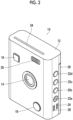
- Fig. 2 is a front perspective view showing an example of the digital camera with a printer.
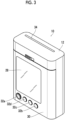
- Fig. 3 is a rear perspective view of the digital camera with a printer shown in Fig. 2 .
- the digital camera 10 with a printer includes a portable camera body 12.
- the camera body 12 has a vertically long rectangular shape in which a thickness in a forward-backward direction is thin and a dimension in a vertical direction is longer than a dimension in a horizontal direction.
- an imaging lens 14, a release button 16, a sound recording button 18, and a strobe emitting window 20 are provided on a front surface of the camera body 12.
- a power button 22a, a menu button 22b, an OK button 22c, a mode switching button 22d, microphone holes 24, and speaker holes 26 are provided on one side surface of the camera body 12.
- the release button 16 is a button for instructing the recording of the image.
- the sound recording button 18 is a button for switching a sound recording mode.
- the power button 22a is a button for turning on and off a power of the digital camera 10 with a printer.
- the menu button 22b is a button for calling a menu screen.
- the OK button is a button for instructing OK.
- the mode switching button 22d is a button for switching between an auto print mode and a manual print mode in an imaging mode.
- a display 28, a film lid cover 30, and various operation buttons are provided on a rear surface of the camera body 12.
- the film lid cover 30 is a cover that opens and closes a film loading chamber.
- a joystick 32a, a print button 32b, a playback button 32c, a cancel button 32d are included in the operation buttons.
- the print button 32b is a button for instructing printing.
- the playback button 32c is a button for instructing switching to a playback mode.
- the cancel button 32d is a button for instructing canceling of the operation.
- a film discharge port 34 is provided on an upper surface of the camera body 12. The printed instant film is discharged through the film discharge port 34.
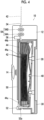
- Fig. 4 is a cross-sectional view showing a schematic configuration of a printer portion.
- the digital camera 10 with a printer comprises, as components of the printer portion which a print unit, a film loading chamber 50, a film delivery mechanism 52, a film transport mechanism 54, and a print head 56.
- the film loading chamber 50 is a loading portion of the instant film pack 40.
- the film loading chamber 50 includes a recess portion into which the instant film pack 40 is fitted, and is opened and closed by the film lid cover 30.
- the film lid cover 30 is closed, and thus, the film loading chamber 50 is sealed in a darkroom state.
- the instant film pack 40 has a structure in which a plurality of instant films 42 is accommodated in a case 44.
- Fig. 5 is a perspective view of the instant film pack.
- Fig. 6 is a front view of the instant film
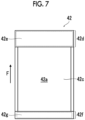
- Fig. 7 is a rear view of the instant film.
- a direction indicated by an arrow F is a delivery direction of the instant film 42.
- the instant film 42 is delivered in the direction indicated by the arrow F, and is discharged from the case 44.
- the instant film 42 is an example of a medium for printing.
- the instant film 42 is an instant film of a so-called "mono-sheet type" (also referred to as a sheet film type or an integral film), and is an instant film of a type in which an image appears on a back side of an exposure surface.
- the instant film 42 has a rectangular card shape.
- the instant film 42 is configured such that one surface is an exposure surface 42a and the other surface is an observation surface 42b.
- the exposure surface 42a is a surface on which an image is recorded through exposing
- the observation surface 42b is a surface on which the recorded image is observed.
- an exposure region 42c, a pod portion 42d, and a trap portion 42f are provided on the exposure surface 42a of the instant film 42.
- the exposure region 42c is a region in which the image is recorded through exposing.
- the exposure region 42c is a region in which the instant film 42 can be printed.
- the pod portion 42d and the trap portion 42f are arranged in front and back in the delivery direction F with the exposure region 42c interposed therebetween.
- the pod portion 42d is disposed in front of the exposure region 42c in the delivery direction F.
- a developing solution pod 42e that contains a developing solution is provided within the pod portion 42d.
- the trap portion 42f is disposed in the back of the exposure region 42c in the delivery direction F.
- An absorbent 42g is provided within the trap portion 42f.
- the print head 56 records the image on the instant film 42 delivered from the instant film pack 40.
- the print head 56 is a line-type exposure head.
- the print head 56 irradiates the exposure surface 42a of the instant film 42 transported by the film transport mechanism 54 with print light line by line, and records the image on the instant film 42 in a single pass.
- the analog signal processing unit 68 acquires analog image signal for each pixel output from the image sensor 64, converts the analog image signal into a digital image signal by performing predetermined signal processing (for example, sampling two correlation pile or amplification processing), and outputs the digital image signal.
- predetermined signal processing for example, sampling two correlation pile or amplification processing
- the digital signal processing unit 70 acquires the digital image signal output from the analog signal processing unit 68, and generates image data by performing predetermined signal processing (for example, gradation transformation processing, white balance correction processing, gamma-correction processing, demosaicing, or YC conversion processing).
- predetermined signal processing for example, gradation transformation processing, white balance correction processing, gamma-correction processing, demosaicing, or YC conversion processing.
- the display 28 is, for example, a liquid crystal display (LCD), an organic electro-luminescence display (OLED), a plasma display, a field emission display (FED), or electronic paper.
- the display controller 76 displays a video on the display 28 under the control using the camera controller 100.
- the short-range wireless communication unit 78 communicates with an external device through the antenna 80 in a wireless manner under the control using the camera controller 100.
- short-range wireless communication such as NFC standard, BlueTooth, or WiFi is performed as the communication.
- the film transport drive unit 84 includes a motor that drives the transport roller pair 54A of the film transport mechanism 54 and a drive circuit thereof, and a motor that drives the spreading roller pair 54B and a drive circuit thereof, and operates the transport roller pair 54A and the spreading roller pair 54B by driving the motor of the transport roller pair 54A and the motor of the spreading roller pair 54B under the control using the camera controller 100.
- the head drive unit 86 includes a drive circuit of the print head 56, and drives the print head 56 under the control using the camera controller 100.
- the strobe 88 comprises, as a light source, a xenon tube or a light emitting diode (LED).
- the strobe emits the light source, and irradiates the subject with strobe light.
- the strobe light is irradiated from the strobe emitting window 20 (see Fig. 2 ) provided on the front surface of the camera body 12.
- the strobe emitting controller 90 includes a drive circuit of the strobe 88, and emits the strobe 88 according to a command from the camera controller 100.
- the microphone 92 collects external sound through the microphone holes 24 (see Fig. 2 ) provided at the camera body 12.
- the microphone 92 is an example of a sound collection unit.
- the speaker 94 outputs sound to the outside through the speaker holes 26 provided at the camera body 12.
- the sound signal processing unit 96 converts a sound signal input from the microphone 92 into a digital sound signal by performing predetermined signal processing on the sound signal, and outputs the digital sound signal.
- the sound signal processing unit 96 performs predetermined signal processing on the sound data given from the camera controller 100, and outputs the sound data through the speaker 94.
- the operation unit 98 includes various operation members such as the release button 16, the sound recording button 18, the power button 22a, the menu button 22b, the OK button 22c, the joystick 32a, the print button 32b, the playback button 32c, and the cancel button 32d and a signal processing circuit, and outputs a signal based on an operation of each operation member to the camera controller 100.
- the camera controller 100 is a controller that generally controls the entire operation of the digital camera 10 with a printer, and is a computer comprising a central processing unit (CPU), a read only memory (ROM), and a random access memory (RAM).
- the computer realizes various functions as the camera controller 100 by executing a predetermined control program.
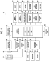
- Fig. 9 is a block diagram of main functions realized by the camera controller.
- the camera controller 100 functions as an imaging controller 100A, a sound recording controller 100B, an identification information generation unit 100C, an upload unit 100D, a communication management unit 100E, a two-dimensional code generation unit 100F, a print controller 100G, and a playback controller 100H by executing the predetermined control program.
- the imaging controller 100a controls imaging. That is, the imaging controller captures the image by controlling the imaging lens 14 and the image sensor 64 which constitute the imaging unit, and performs processing for recording the image data obtained through the imaging in the memory 72. Live preview processing is performed at the time of imaging. That is, the video captured by the image sensor 64 is displayed on the display 28 in real time. Accordingly, imaging can be performed while using the display 28 as a live preview monitor. The imaging for recording is performed by pressing the release button 16.
- the sound recording controller 100B controls the sound recording. In a case where the image with sound is captured, the sound recording controller 100B obtains the sound data through the microphone 92, and performs processing for recording the obtained sound data in association with the image data obtained through the imaging in the memory 72. In a case where the sound is added to the captured image, the sound recording controller 100B obtains the sound data through the microphone 92, and performs processing for recording the obtained sound data in association with target image data in the memory 72. In a case where rewriting of the sound on the captured image with sound is instructed, the sound recording controller 100B obtains the sound data through the microphone 92, and performs processing for rewriting the sound data of the target image data with the obtained sound data.
- the identification information generation unit 100C performs processing for generating predetermined identification information.
- the image data with sound is printed
- the image data and the sound data are stored in the data storage server 200.
- the identification information is used at the time of storing the image data and the sound data in the data storage server 200. That is, the identification information is used for specifying the data in the data storage server 200.
- the upload unit 100D performs processing for uploading the image data and the sound data in the data storage server 200.
- the data is uploaded to the data storage server 200 through the upload terminal 300. Accordingly, the upload unit 100D transmits the data to the upload terminal 300.
- the communication management unit 100E manages communication with the upload terminal 300. More specifically, the communication management unit manages a connection state of the communication with the upload terminal 300, and determines whether or not to transmit the data to the upload terminal 300.
- the two-dimensional code generation unit 100F In a case where the image data with sound is printed, the two-dimensional code generation unit 100F generates a two-dimensional code obtained by encoding predetermined information. As stated above, in a case where the image data with sound is printed, the image data and the sound data are stored in the data storage server 200. The two-dimensional code generation unit 100F generates a two-dimensional code obtained by encoding access information to the image data and the sound data stored in the data storage server 200.
- the two-dimensional code is an example of recording information
- the two-dimensional code generation unit 100F is an example of a recording information generation unit.
- the two-dimensional code is a QR code (registered trademark).
- the print controller 100G controls printing. Initially, in the printing, image data for printing is generated from the image data instructed to be printed. Subsequently, the print controller drives the print head 56 based on the generated image data for printing, and prints the image on the instant film 42. Accordingly, the print controller 100G has a function of a print image data generation unit and a print drive unit.
- the print image data generation unit performs processing for generating the image data for printing
- the print drive unit performs processing for driving the print head 56, the film delivery mechanism 52, and the film transport mechanism 54.
- the print controller 100G adds the two-dimensional code, and prints the image. Specifically, the print controller generates, as the image data for printing, image data combined with the two-dimensional code, and prints the generated image data with the two-dimensional code.
- the two-dimensional code is combined so as to be overlapped with a part of the image.
- the playback controller 100H controls playing of the recorded image. That is, the reproduction controller reads out the image data from the memory 72, and performs processing for displaying the readout image data on the display 28. At this time, in a case where image data as a playback target is the image data with sound, the playback controller reads out the sound data, and outputs the readout sound through the speaker 94. Frame-by-frame advancing of the image is performed by an operation of the joystick 32a.
- the data storage server 200 stores the image data captured by the digital camera 10 with a printer and the sound data associated with the image data.
- the data storage server 200 is an example of a server.
- the data storage server 200 is a general server computer.
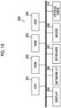
- Fig. 10 is a block diagram showing an example of a hardware configuration of the data storage server.
- the data storage server 200 comprises a CPU 201 that controls the entire operation, a ROM 202 that stores a program used for driving the CPU 201 such as an initial program loader (IPL), a RAM 203 that is used as a work area of the CPU 201, a hard disk drive (HDD) 204 that stores various programs and various data for the data storage server 200, a display 205, a network interface (I/F) 206 for performing data communication by using the communication network 2, a keyboard 207, a mouse 208, and an optical drive 210.
- IPL initial program loader
- HDD hard disk drive
- I/F network interface
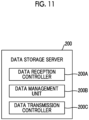
- Fig. 11 is a block diagram of main functions provided by the data storage server.
- the CPU 201 executes a predetermined program, and thus, the data storage server 200 functions as a data reception controller 200A, a data management unit 200B, and a data transmission controller 200C.
- the data reception controller 200a communicates with the upload terminal 300 via the communication network 2, and receives data for storing from the upload terminal 300.
- the data management unit 200B performs processing for recording the data received from the upload terminal 300 in a storage unit and performs readout processing the corresponding data from the storage unit according to a download request from the data playback terminal 400.
- the storage unit is the HDD 204.
- the data management unit 200B constructs a predetermined database, and stores the image data and the sound data associated with the image data in the HDD 204.
- the data transmission controller 200C communicates with the data playback terminal 400 via the communication network 2, and transmits the data to the data playback terminal 400 according to a download request for the corresponding data from the data playback terminal 400.
- the upload terminal 300 is a terminal that uploads the data to the data storage server 200, receives the data for storing (the image data of the printed image and the sound data associated with the image data) from the digital camera 10 with a printer, and transmits the received data to the data storage server 200.
- the upload terminal 300 is a computer having a communication function, particularly, a mobile computer such as a smartphone, a tablet terminal, a laptop computer, or a PDA, and communicates with the digital camera 10 with a printer through the short-range wireless communication (for example, NFC standard, BlueTooth, or WiFi).
- the upload terminal communicates with the data storage server 200 via the communication network 2.
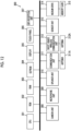
- Fig. 12 is a block diagram showing an example of a hardware configuration of the upload terminal.
- Fig. 12 shows an example of a hardware configuration in a case where the upload terminal 300 is the smartphone.
- the upload terminal 300 comprises a CPU 301 that controls the entire operation, a ROM 302 that stores a basic input and output program, a RAM 303 that is used as a work area of the CPU 301, an electrically erasable and programmable ROM (EEPROM) 304 that stores various programs including an operating system executed by the CPU 301 and various data, a display 305, a touch panel 306 that detects a touch operation on a display screen, a Global Positioning Systems (GPS) reception unit 307 that receives a GPS signal including positional information (latitude, longitude, and altitude) of the upload terminal 300 by a GPS satellite or an Indoor Messaging System (IMES) as an indoor GPS, a camera unit 308 that includes an imaging lens and an image sensor and electronically captuers an image, a microphone unit 309 that includes a microphone and receives sound, a speaker unit 310 that includes a speaker and outputs sound, a communication unit 311 that communicates with the nearest base station 2a
- GPS Global Positioning Systems
- Fig. 13 is a block diagram of main functions provided by the upload terminal.
- the CPU 301 executes a predetermined program, and thus, the upload terminal 300 functions as an upload data obtaining unit 300A and a data transmission unit 300B.
- the upload data obtaining unit 300A communicates with the digital camera 10 with a printer in a short-range wireless manner, and receives upload data (the image data and the sound data associated with the image data) from the digital camera 10 with a printer.
- the data transmission unit 300B communicates with the data storage server 200 via the communication network 2, and transmits (uploads) the data received from the digital camera 10 with a printer to the data storage server 200.
- Fig. 14 is a block diagram showing an example of a hardware configuration of the data playback terminal.
- Fig. 14 shows an example of a hardware configuration in a case where the data playback terminal 400 is the smartphone.
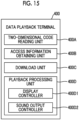
- Fig. 15 is a block diagram of main functions provided by the data playback terminal.
- the two-dimensional code reading unit 400A is realized by the camera unit 408, and reads a two-dimensional code by imaging the two-dimensional code by the camera unit 408.
- the two-dimensional code reading unit 400A is an example of a recording information reading unit.
- the access information obtaining unit 400B obtains access information to the image data and the sound data of the image printed on the instant film 42 by reading the two-dimensional code printed on the instant film 42 by using the two-dimensional code reading unit 400A.
- the download unit 400C accesses the data storage server 200 based on the access information obtained by the access information obtaining unit 400B, and downloads the corresponding image data and sound data.
- the playback processing unit 400D performs processing for playing the downloaded image data and sound data.
- the playback processing unit 400D comprises a display controller 400D1 that displays the downloaded image data on the display 405 which is a display unit and a sound output controller 400D2 that outputs the downloaded sound data from the speaker unit which is a sound output unit.
- the digital camera 10 with a printer has, as an operation mode, the imaging mode and the playback mode.
- the imaging mode is a mode in which an image is captured.
- the playback mode is a mode in which the captured image is played.
- the auto print mode is a mode in which the captured image is automatically printed.
- the manual print mode is a mode in which the captured image is printed according to a command of the user. Switching between the modes is performed by pressing the mode switching button 22d.
- the mode (sound recording mode) in which the image with sound is captured in each mode of the imaging mode.
- the normal sound recording mode is a mode in which sound for a predetermined time before and after releasing is recorded.
- the after recording mode is a mode in which sound is input after the imaging. Switching between the sound recording modes is performed by pressing the sound recording button 18. Specifically, whenever the sound recording button 18 is pressed, the normal sound recording mode, the after recording mode, and the sound recording mode are sequentially turned off.
- Fig. 16 is a flowchart showing a procedure of setting for each mode.
- step S1 it is determined whether or not the digital camera with a printer is in the imaging mode. In a case where the digital camera with a printer is not in the imaging mode, it is determined that the digital camera with a printer is in the playback mode, and the processing in the playback mode is performed (step S2).
- step S3 it is determined whether or not the digital camera with a printer is in the manual print mode. In a case where the digital camera with a printer is not in the manual print mode, it is determined that the digital camera with a printer is in the auto print mode, and the processing in the auto print mode is performed (step S4). In a case where the digital camera with a printer is in the manual print mode, the processing in the manual print mode is performed (step S5).
- the manual print mode is a mode in which the captured image is printed according to a print command from the user after the imaging.
- Fig. 17 is a flowchart showing an operation procedure in the manual print mode.
- step S11 it is determined whether or not the sound recording mode is turned on. In a case where the sound recording mode is not turned on, the imaging is performed without performing the sound recording. Meanwhile, in a case where the sound recording mode is turned on, it is determined whether or not the normal sound recording mode is set (step S12). In a case where the normal sound recording mode is set, the imaging is performed in the normal sound recording mode. That is, the sound recording is performed simultaneously with the imaging. Meanwhile, in a case where the normal sound recording mode is not set, the imaging is performed in the after recording mode. That is, the sound is recorded after the imaging.
- Fig. 18 is a flowchart showing an operation procedure in a case where the sound recording mode is turned off in the manual print mode.
- live preview is displayed on the display 28 (step S21). That is, the video captured by the image sensor 64 is displayed on the display 28 in real time. The user checks composition and a focusing state on the subject while viewing the display of the display 28.
- step S22 Thereafter, it is determined whether or not an imaging command is issued (step S22).
- the imaging command is performed by pressing the release button 16.
- the imaging processing is performed (step S23). That is, the image is acquired through the image sensor 64.
- the image data obtained through the imaging is converted into a predetermined file format such as Joint Photographic Experts Group (JPEG), RAW, Tagged Image File Format (TIFF), Graphics Interchange Format (GIF), or bitmap, and the converted image data is recorded in the memory 72 (step S24).
- JPEG Joint Photographic Experts Group
- RAW Rasteret Transfer Agent
- TIFF Tagged Image File Format
- GIF Graphics Interchange Format
- bitmap bitmap
- the image data obtained through the imaging is previewed on the display 28 (step S25).
- the user checks the display of the display 28, and determines whether or not it is necessary to print the image. In a case where the user prints the image, the user presses the print button 32b, in a case where the user does not print the image, the user presses the cancel button 32d or the release button 16.
- step S26 It is determined whether or not a print command is issued based on an operation of the user during previewing (step S26). In a case where the print command is issued, print processing is performed (step S27). The print processing will be described below. Thereafter, it is determined whether or not the mode is ended (step S28). That is, it is determined whether or not the mode is switched to another mode. In a case where the mode is ended, the processing is ended.
- the captured image is printed after the imaging according to the print command from the user.
- Fig. 19 is a flowchart showing an operation procedure in a case where the normal sound recording mode is turned on in the manual print mode.
- live preview is displayed on the display 28.
- the acquisition of sound from the microphone 92 is started at the same time as the live preview (step S31).
- the acquired sound is buffered for a predetermined time, and is then removed sequentially. That is, the sound is buffered as much as necessary for recording the sound. For example, in a case where sound for five seconds before and after the imaging is recorded, sound for at least the past five seconds is buffered.
- step S32 it is determined whether or not an imaging command is issued.
- the imaging processing is performed (step S33). That is, the acquisition of the image is performed through the image sensor 64, and the acquisition of the sound is performed through the microphone 92. The sound for the predetermined time before and after the imaging is acquired as the sound.
- the image data and the sound data obtained through the imaging are converted into a predetermined file format, and are recorded in association with each other in the memory 72 (step S34).
- An appropriate sound file such as Moving Picture Experts Group (MPEG)-1 Audio Layer 3 (MP3), RealAudio (registered trademark), Musical Instruments digital Interface (MIDI) (registered trademark) file, or WAVE file can be used as the sound data file.
- MPEG Moving Picture Experts Group
- MP3 RealAudio
- MIDI Musical Instruments digital Interface
- WAVE file can be used as the sound data file.
- step S35 the image data obtained through the imaging is previewed on the display 28 (step S35). It is determined whether or not the print command is issued based on an operation of the user during previewing (step S36). In a case where the print command is issued, print processing is performed (step S37). The print processing will be described below. Thereafter, it is determined whether or not the mode is ended (step S38). In a case where the mode is ended, the processing is ended.
- the sound for the predetermined time before and after the imaging is recorded at the same time as the imaging, and the sound and the image are recorded in the memory 72.
- the captured image data is printed according to the print command from the user.
- Fig. 20 is a flowchart showing an operation procedure in a case where the after recording mode is turned on in the manual print mode.
- live preview is displayed on the display 28 (step S41). Thereafter, it is determined whether or not an imaging command is issued (step S42). In a case where the imaging command is issued, the imaging processing is performed (step S43), and the image data obtained through the imaging is recorded in the memory 72 (step S44). In a case where the imaging is performed, the image data obtained through the imaging is previewed on the display 28 (step S45).
- Fig. 21 is a diagram showing an example of a preview screen in the after recording mode.
- an image PVI obtained through imaging and a message ME for checking whether or not it is necessary to record sound are displayed on a screen of the display 28.
- the sound recording button 18 (see Fig. 2 ) is pressed.
- the cancel button 32d is pressed. It is determined whether or not a sound recording command is issued based on an operation of the user during previewing (step S46).
- step S47 sound recording processing is performed. That is, sound for a predetermined time (for example, ten seconds) is acquired through the microphone 92. The sound data of the acquired sound is recorded in association with the image data obtained through the imaging in the memory 72 (step S48).
- a predetermined time for example, ten seconds
- step S49 it is determined whether or not the print command is issued. It is determined whether or not the print command is issued even in a case where the sound recording is canceled in step S46. In a case where the print command is issued, print processing is performed (step S50). The print processing will be described below. Thereafter, it is determined whether or not the mode is ended (step S51). In a case where the mode is ended, the processing is ended.
- the sound for the predetermined time is recorded after the imaging according to the command from the user.
- the recorded sound data is recorded in association with the image data in the memory 72.
- the captured image data is printed according to the print command from the user.
- the auto print mode is a mode in which the captured image is automatically printed after the imaging.
- Fig. 22 is a flowchart showing an operation procedure in the auto print mode.
- step S61 it is determined whether or not the sound recording mode is turned on. In a case where the sound recording mode is not turned on, the imaging is performed without performing the sound recording. Meanwhile, in a case where the sound recording mode is turned on, it is determined whether or not the normal sound recording mode is set (step S62). In a case where the normal sound recording mode is set, the imaging is performed in the normal sound recording mode. That is, the sound recording is performed simultaneously with the imaging. Meanwhile, in a case where the normal sound recording mode is not set, the imaging is performed in the after recording mode. That is, the sound is recorded after the imaging.
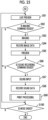
- Fig. 23 is a flowchart showing an operation procedure in a case where the sound recording mode is turned off in the auto print mode.
- live preview is displayed on the display 28 (step S71). Thereafter, it is determined whether or not an imaging command is issued (step S72). In a case where the imaging command is issued, the imaging processing is performed (step S73), and the image data obtained through the imaging is recorded in the memory 72 (step S74). The captured image is printed (step S75). The print processing will be described below. Thereafter, it is determined whether or not the mode is ended (step S76). In a case where the mode is ended, the processing is ended.
- the captured image is automatically printed after the imaging.
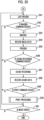
- Fig. 24 is a flowchart showing an operation procedure in a case where the normal sound recording mode is turned on in the manual print mode.
- live preview is displayed on the display 28.
- the acquisition of sound from the microphone 92 is started at the same time as the live preview (step S81).
- the acquired sound is buffered for a predetermined time, and is then removed sequentially.
- it is determined whether or not an imaging command is issued (step S82).
- the imaging processing is performed (step S83), and the image data and the sound data obtained through the imaging is recorded in the memory 72 (step S84).
- the captured image is printed (step S85). The print processing will be described below.
- it is determined whether or not the mode is ended (step S86). In a case where the mode is ended, the processing is ended.
- the sound for the predetermined time before and after the imaging is recorded at the same time as the imaging, and the sound and the image are recorded in the memory 72.
- the captured image is automatically printed after the imaging.
- Fig. 25 is a flowchart showing an operation procedure in a case where the after recording mode is turned on in the manual print mode.
- step S100 it is determined whether or not the mode is ended. In a case where the mode is ended, the processing is ended.
- the sound for the predetermined time is recorded after the imaging according to the command from the user.
- the recorded sound data is recorded in association with the image data in the memory 72.
- the captured image data is automatically printed after the imaging.
- Switching from the imaging mode to the playback mode is performed by pressing the playback button 32c. Switching from the playback mode to the imaging mode is performed by pressing the release button 16.
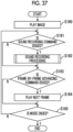
- Fig. 26 is a flowchart showing an operation procedure in the playback mode.
- the image data of the image captured last is read out from the memory 72, and is played and displayed on the display 28 (step S110).
- step S111 it is determined whether or not the image data being played is the image data with sound.
- step S112 it is determined whether or not a sound playback command is issued.
- the sound playback command is issued by pressing the playback button 32c.
- Fig. 27 is a diagram showing an example of display of the display in a case where the image data with sound is displayed.
- an icon IC indicating that an image IM being displayed is the image with sound is displayed. Accordingly, the user can recognize that the image IM being displayed is the image with sound.
- step S113 sound playback processing is performed (step S113). That is, the sound data associated with the image data being played is read out from the memory 72, and is output from the speaker 94. Accordingly, the user can listen the sound associated with the image.
- step S114 It is determined whether or not a print command is issued during playing (step S114).
- the print command is issued by pressing the print button 32b. In a case where the print button 32b is pressed, the image being played is printed (step S115). The print processing will be described below.
- step S116 It is determined whether or not a frame-by-frame advancing command is issued during playing (step S116).
- a frame-by-frame advancing command is performed by the joystick 32a, and the frame-by-frame advancing is performed in a case where the joystick 32a is operated in a horizontal direction. That is, the next frame is read out from the memory 72, and is played and displayed on the display 28 (step S117).
- the joystick 32a is operated in an up-down direction, the image being displayed is zoomed in and zoomed out.
- step S118 it is determined whether or not the mode is ended. In a case where the mode is ended, the processing is ended.
- the image being played can be printed according to the print command from the user.
- the image being played is the image with sound
- the sound associated with the image can be played according to the command from the user.
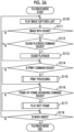
- Fig. 28 is a flowchart showing a processing procedure at the time of printing the image.
- step S120 it is determined whether or not image data as a processing target is the image data with sound (step S120). That is, it is determined whether or not the image data is recorded in association with the sound data.
- the print processing is performed according to a normal procedure.
- the image data for printing is generated (step S121). That is, the image data to be printed on the instant film 42 by using the print head 56 is generated.
- the image obtained by horizontally inverting the image for displaying is generated as the image for printing. Since the instant film 42 is loaded upside down, the vertically inverted image is generated.
- the printing is performed after the image data for printing is generated (step S122).
- one instant film 42 is delivered from the instant film pack 40.
- the delivered instant film 42 is transported toward the film discharge port 34 at a predetermined speed.
- the light is applied from the print head 56 during the transporting, and the image is recorded on the exposure surface.
- the exposed instant film 42 is developed by passing between the spreading roller pair 54B, and is discharged through the film discharge port 34.
- step S 123 it is initially determined whether or not to upload the image data and the sound data to the data storage server 200 (step S 123).
- the image data as the printing data is the image data with sound
- a message for inquiring about whether or not it is necessary to upload the data to the data storage server 200 is displayed on the display 28.
- the user determines whether or not it is necessary to upload the data according to the message displayed on the screen.
- the user presses the OK button 22c the user presses the cancel button 32d.
- the camera controller 100 determines whether or not it is necessary to upload the data based on the operation of the OK button 22c and the cancel button 32d.
- the print processing is performed according to the normal procedure similarly to the case where the image data without sound is printed (step S121 and S122).
- upload processing is performed (step S124).
- the dimensional code (recording information) obtained by encoding the access information to the uploaded data and the image are printed on the instant film 42. Accordingly, the series of operation systems until an upload command is issued are an example of a recording information print setting unit that sets whether or not to print the recording information.
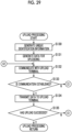
- Fig. 29 is a flowchart showing a procedure of the upload processing.
- unique identification information is generated (step S130).
- the identification information is generated in order to distinguish between the uploaded data and other data in a data storage destination.
- information obtained by combining information on a device model of the digital camera 10 with a printer, information on a serial number of the digital camera 10 with a printer, information on the cumulative number of times of the printing is generated as the unique identification information.
- the "information on the device model” is information for specifying the device model of the digital camera 10 with a printer, and corresponds to, for example, a product name and a product code.
- serial number is an identification number given to the product, particularly, is a number to which numerals and alphabetic numerals constituting the number are given based on a predetermined rule or system.
- the serial number is also referred to as a manufacturing number.
- the serial number is an example of the unique identification number assigned to the digital camera with a printer.
- the "cumulative number of times of the printing is the total number of times of the printing performed until a current point of time since the digital camera 10 with a printer is shipped. Accordingly, a case where the digital camera with a printer has not printed yet since the digital camera with a printer is shipped is "0", and a case where the digital camera with a printer has printed by ten times is "10".
- the camera controller 100 counts the cumulative number of times of the printing, and records the counted cumulative number in the memory 72.
- the information on the cumulative number of times of the printing is expressed by a prescribed number of digits (for example, five digits).
- the identification information is generated by arranging the information items on the "device model", the "serial number”, the "cumulative number of times of the printing” in this order. For example, in a case where a device model name is "instax_mini_xx”, the serial number is "7T00XXX”, the cumulative number of times of the printing is "00098”, the identification information is "instax_mini_xx7T00XXX00098".
- the data for uploading is generated after the identification information is generated (step S131). That is, the data to be uploaded to the data storage server 200 is generated.
- the data is generated as the data including the identification information. For example, data having a header to which the identification information is added is generated. Alternatively, data having a file name as the identification information is generated.
- the image data and the sound data may be individually generated as the data for uploading, or may be generated as one file.
- step S132 the communication with the upload terminal 300 is performed (step S132). It is determined whether or not the communication is established (step S133).
- the data for uploading is transmitted to the upload terminal 300 (step S134).
- the upload terminal 300 receives the data, and uploads the received data to the data storage server 200.
- the camera controller 100 determines whether or not the upload has succeeded based on a transmission result of the data for uploading by the upload terminal 300 (step S135). In a case where the upload has succeeded, the upload processing is ended.
- Fig. 30 is a sequence diagram of the upload processing.
- the upload terminal 300 transmits a connection request to the data storage server 200.
- the data storage server 200 responds to the connection request, and the communication between the upload terminal 300 and the data storage server 200 is established.
- the digital camera with a printer transmits a connection request to the upload terminal 300.
- the upload terminal 300 responds to the connection request, and the communication between the digital camera 10 with a printer and the upload terminal 300 is established.
- the data for uploading is transmitted to the upload terminal 300 from the digital camera 10 with a printer.
- the upload terminal 300 notifies the digital camera 10 with a printer of reception completion.
- the received data for uploading is temporarily stored in the memory.
- the upload terminal 300 transmits the received data for uploading to the data storage server 200.
- the data storage server 200 stores the received data. More specifically, the received image data and the sound data associated with the image data are stored in association with each other in the database. At this time, the image data and the sound data are recorded by using the identification information added to the data. Accordingly, the image data and the sound data can be specified.
- the data storage server 200 transmits a reception completion notification to the upload terminal 300.
- the upload terminal 300 notifies the digital camera 10 with a printer of upload completion.
- the image data and the sound data are uploaded to the data storage server 200 from the digital camera 10 with a printer.
- Fig. 31 is a flowchart showing a processing procedure in a case where the communication is not enabled or the upload processing has failed.
- the camera controller 100 of the digital camera 10 with a printer displays a predetermined error message (for example, a "communication error") on the display 28 (step S140).
- a predetermined error message for example, a "communication error”
- a message for inquiring about whether or not to continue to upload the data is displayed at the same time as the communication error.
- the camera controller 100 determines whether or not to cancel the upload processing based on an operation input from the user (step S141). In a case where the user cancels the upload processing, the user presses the cancel button 32d, and in a case where the user does not cancel the upload processing, the user presses the OK button 22c. In a case where the user does not cancel the upload processing, the processing returns to step S132, and the digital camera attempts to communicate with the upload terminal 300 again (S132 of Fig. 29 ).
- the camera controller 100 displays an error message of uploading cancelation (for example, "upload is canceled") on the display 28 (step S142).
- an error message of uploading cancelation for example, "upload is canceled"
- a message for inquiring about whether or not to cancel the printing for example, "do you want to print image?" is displayed at the same time of the error message of uploading cancelation.
- the camera controller 100 determines whether or not to cancel the printing based on an operation input from the user (step S143). In a case where the user cancels the upload processing, the user presses the cancel button 32d, and in a case where the user does not cancel the upload processing, the user presses the OK button 22c. In a case where the user does not cancel the printing, the print processing is performed. In this case, the print processing is performed according to the normal procedure similarly to the case where the image data without sound is printed. That is, as shown in Fig. 28 , the image data for printing is generated (step S121), and the printing is performed based on the generated image data (step S122).
- the message of the print cancelation is displayed on the display 28 (step S144), and the print processing is ended.
- the camera controller inquires about whether or not to cancel the upload processing and the print processing, and the processing corresponding to a command from the user is performed.
- the camera controller inquires about whether or not to cancel the upload processing and the print processing, and the processing corresponding to a command from the user is performed.
- the two-dimensional code is generated as shown in Fig. 29 (step S125).
- the two-dimensional code is obtained by encoding the access information for accessing the uploaded image data and sound data. More specifically, the two-dimensional code is obtained by encoding the information for accessing the image data and the sound data stored in the data storage server 200 over the network, and is obtained by encoding the Universal Resource Locator (URL) of the data.
- the uploaded image data and sound data are assigned the unique identification information, and are stored in the prescribed data storage server 200 by using the unique identification information. Accordingly, the storage location can be specified in the individual digital camera 10 with a printer.
- a certain URL which is the access information is generated based on the identification information assigned to the uploaded image data and sound data and information on the storage location (information on the data storage server 200), and the generated URL is encoded as the two-dimensional code.
- a QR code registered trademark
- the image data for printing is generated (step S126).
- the two-dimensional code is included in the image data for printing.
- Fig. 32 is a conceptual diagram of the generation of the image data for printing in a case where the image data with sound is printed.
- image data PRI1 for printing is generated by combining a two-dimensional code QR with an image PRI0 to be printed.
- the two-dimensional code QR is combined so as to be overlapped with a part of the image PRI0 to be printed. That is, the two-dimensional code is overlaid with a part of the image. Accordingly, a portion of the image PRI0 to be printed with which the two-dimensional code QR is overlaid cannot be viewed.
- the two-dimensional code QR is combined at a position determined in advance. In the present embodiment, the two-dimensional code is combined in a lower right corner of the image PRI0 to be printed.
- the processing for horizontally inverting the image is performed.
- the processing for vertically inverting the image is performed.
- the printing is performed after the image data for printing is generated (step S127). That is, the instant film 42 is delivered from the instant film pack 40, the light is applied from the print head 56 during the transporting, and the image is recorded on the exposure surface of the instant film 42. The exposed instant film 42 is developed by passing between the spreading roller pair 54B, and is then discharged through the film discharge port 34.
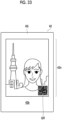
- Fig. 33 is a diagram showing an example of a printing result of the image data with sound.
- the image and the two-dimensional code QR are printed on the instant film 42 which is a printout.
- the image is displayed on the observation surface 42b on the opposite side of the exposure surface, and is displayed on the observation region 42h inside the frame 42i. Since the observation region 42h is slightly narrower than the exposure region, the substantially trimmed image is displayed.
- the two-dimensional code QR printed on the instant film 42 is read by the data playback terminal 400, and thus, the image printed on the instant film 42 and the sound associated with the image can be viewed on the data playback terminal 400.
- the image and the two-dimensional code QR printed on the instant film 42 are read by the data playback terminal 400, and thus, the image printed on the instant film 42 and the sound associated with the image can be played on the data playback terminal 400.
- the data playback terminal 400 obtains the access information to the image data and the sound data from the two-dimensional code QR, accesses the storage location of the data based on the obtained access information, and downloads and plays the data.
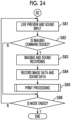
- Fig. 34 is a flowchart showing a procedure of processing for downloading and playing the image data and the sound data.
- the user who obtains the instant film 42 with the two-dimensional code reads the two-dimensional code QR printed on the instant film 42 on the data playback terminal 400 (step S150).
- the data playback terminal 400 obtains the access information from the read two-dimensional code QR (step S151). That is, the data playback terminal obtains the information (URL) for accessing the image data of the image printed on the instant film 42 and the sound data associated with the image data. The data playback terminal accesses the storage location of the data based on the obtained access information, and downloads the data (step S152).
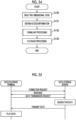
- Fig. 35 is a sequence diagram of download processing.
- the data playback terminal 400 transmits a connection request to the data storage server 200.
- the data storage server 200 responds to the connection request, and the communication between the data playback terminal 400 and the data storage server 200 is established.
- the data playback terminal 400 requests the data storage server 200 to transmit the data. That is, the data playback terminal requests the data storage server to transmit the image data of the image printed on the instant film 42 and the sound data associated with the image data.
- the data storage server 200 responds to the request, searches for the data from the database, and reads outs the data.
- the data storage server transmits the readout data to the data playback terminal 400.
- the data playback terminal 400 receives the data transmitted from the data storage server 200. Thus, the download processing is completed.
- the data playback terminal 400 plays the image data and the sound data downloaded from the data storage server 200 (step S153). Specifically, the downloaded image data is displayed on a display 405. The downloaded sound data is output from a speaker unit 410.
- Fig. 36 is a diagram showing comparison of the image printed on the instant film with the image played on the data playback terminal.
- the two-dimensional code QR is displayed so as to be overlapped with the image printed on the instant film 42. Meanwhile, the image without the two-dimensional code is displayed on the display 405 of the data playback terminal 400. Accordingly, it is possible to browse a complete image. As stated above, the image of which the peripheral portion is trimmed is printed on the instant film 42, but the original image of which the peripheral portion is not trimmed is displayed on the display 405. Accordingly, it is possible to view a portion that cannot be printed can on the instant film 42.
- the smartphone since the smartphone has a function of enlarging the image, it is possible to check the details of the image by using the enlarging function. Accordingly, it is possible to improve convenience of viewing the image.
- the pinch-out operation is an operation for widening a distance between two fingers while touching the screen with the two fingers.
- the user performs a pinch-in operation on the screen of the display 405.
- the pinch-in operation is an operation for narrowing a distance between two fingers while touching the screen with the two fingers.
- the data playback terminal 400 enlarges or reduces the image being played based on a screen operation by the user, and displays the enlarged or reduced image.
- the image and a sound playback button VPB are displayed on the display 405 of the data playback terminal 400.
- the user can repeatedly play the sound by touching the sound playback button VPB.
- the data playback terminal 400 performs play processing of the sound data based on a screen operation by the user.
- the data playback terminal 400 can play the image printed on the instant film 42 and the sound associated with the image by reading the two-dimensional code QR printed on the instant film 42.
- the printing method performed by the digital camera 10 with a printer is not particularly limited.
- the image may be printed by a thermosensitive method by using thermosensitive paper or an ink ribbon.
- the image may be printed by an inkjet method.
- the image data with sound is generated by obtaining the sound data at the time of imaging and recording the sound data in association with the image data obtained through the imaging
- the method of generating the image data with sound is not limited thereto.
- the image data with sound may be generated by inputting sound at any timing after the imaging and recording the sound in association with any image data.
- Fig. 37 is a flowchart showing a processing procedure in a case where the image data with sound is generated after the imaging in the digital camera with a printer.
- the present processing is performed in the playback mode. That is, the captured image is played in the playback mode, any image is selected, and the sound is input. The input of the sound is performed according to the sound recording command.
- the sound recording command is issued by pressing the sound recording button 18.
- the sound recording button 18 is an example of an after recording instructing unit.
- the captured image is played (step S160). That is, one image (for example, the image captured last) recorded in the memory 72 is read out, and is displayed on the display 28.
- the camera controller 100 determines whether or not the sound recording command is issued based on operation information of the sound recording button 18 during the playing of the image (step S161).
- the camera controller 100 performs the sound recording processing (step S162).
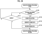
- Fig. 38 is a flowchart showing a procedure of the sound recording processing.
- the camera controller 100 determines whether or not a command to start the sound recording is issued based on an operation input from the user (step S170). For example, the command to start the sound recording is issued by pressing the sound recording button 18. In a case where the cancel button 32d is pressed, the sound recording processing is canceled. In a case where the command to start the sound recording is not issued, the camera controller 100 determines whether or not a cancel command is issued (step S171). In a case where the cancel command is issued, the sound recording processing is ended.
- the sound for the predetermined time is collected through the microphone 92 (step S172). For example, the sound for ten seconds is collected.
- the sound data is generated from the collected sound (step S173), and the generated sound data is recorded in association with the image data of the image being played in the memory 72 (step S174).
- the sound recording processing is ended through the aforementioned steps. Thereafter, as shown in Fig. 37 , it is determined whether or not a frame-by-frame advancing command is issued (step S163). In a case where the frame-by-frame advancing command is issued, the next frame is read out from the memory 72, and is played and displayed on the display 28 (step S164). It is determined whether or not the playback mode is ended (step S165), and the processing is ended in a case where the playback mode is ended.
- the sound data can be freely added later. Accordingly, it is possible to improve convenience.
- the timing of the sound recording is not limited to the example of the aforementioned embodiment.
- the sound for the predetermined time after the imaging may be recorded, or sound for a predetermined time before the imaging may be recorded.
- a sound recording time before the imaging and a sound recording time after the imaging may be different.
- the timing of the sound recording may be optionally set by the user.
- the sound recording time may be optionally set by the user.
- the setting can be performed by calling a recording setting item from the menu screen.
- the sound data associated with the image data is rewritten.
- Fig. 39 is a flowchart showing a processing procedure in a case where the sound data is rewritten in the digital camera with a printer.
- the present processing is performed in the playback mode.
- the captured image is played (step S180). That is, one image (for example, the image captured last) recorded in the memory 72 is read out, and is displayed on the display 28.
- the camera controller 100 determines whether or not the sound recording command is issued based on the operation information of the sound recording button 18 during the playing of the image (step S181). In a case where the sound recording command for the image being played is issued, the camera controller 100 determines whether or not the sound recording for the image is completed (step s182). That is, it is determined whether or not the image data for which the sound recording command is issued is the image data with sound.
- step S189 the sound recording processing is performed according to the procedure shown in Fig. 38 (step S189).
- a message indicating that the sound recording for the image is completed (for example, "sound has been recorded") and a message for inquiring about rewriting (for example, "do you want to rewrite sound?") are displayed on the display 28 (step S183).
- the user instructs the canceling of the rewriting of the sound or the sound recording based on the display of the display 28.
- a rewrite command is issued by pressing the OK button 22c.
- the canceling of the sound recording is performed by pressing the cancel button 32d.
- the series of operation systems until the rewrite command is issued is an example of a sound data rewrite instructing unit.
- the camera controller 100 determines whether or not a command to rewrite the sound data is issued based on an operation input from the user (step S184). In a case where the rewrite command is issued, the camera controller 100 performs the sound recording processing (step S185).
- Fig. 40 is a flowchart showing a procedure of the sound recording processing in a case where the sound data is rewritten.
- the camera controller 100 determines whether or not the command to start the sound recording is issued based on an operation input from the user (step S190). For example, the command to start the sound recording is issued by pressing the sound recording button 18. In a case where the cancel button 32d is pressed, the sound recording processing is canceled. In a case where it is determined that the command to start the sound recording is not issued, the camera controller 100 determines whether or not the cancel command is issued (step S191). In a case where the cancel command is issued, the sound recording processing is ended.
- the sound for the predetermined time is collected through the microphone 92 (step S192). For example, the sound for ten seconds is collected.
- the sound data is generated from the collected sound (step S193), and the generated sound data is overwritten and recorded (step S194). That is, the sound data recorded in association with the image data being played is rewritten with the newly generated sound data.
- step S186 it is determined whether or not a frame-by-frame advancing command is issued. In a case where the frame-by-frame advancing command is issued, the next frame is read out from the memory 72, and is played and displayed on the display 28 (step S187). It is determined whether or not the playback mode is ended (step S188), and the processing is ended in a case where the playback mode is ended.
- the sound data associated with the image data is optionally rewritten in the digital camera with a printer. Accordingly, it is possible to improve convenience.
- the other data may be specified by using one data.
- the method of associating the image data with the sound data is not particularly limited.
- a management file may be prepared, and the association of the image data with the sound data may be managed by using the file.
- the information of the associated data may be recorded in the header portion, and the associated data may be specified.
- the identification information or the information such as the two-dimensional code may be added to the uploaded data, and the uploaded data may be recorded.
- Fig. 41 is a diagram showing an example of a file structure of the image data in a case where the data is uploaded.
- the information such as the two-dimensional code generated at the time of uploading is added to the file of the image data.
- Information on a position at which the two-dimensional code is printed is recorded in the header. Accordingly, it is possible to easily print the image to which the two-dimensional code is added at the time of printing the image again.
- the sound data may be added to the file of the image data. Accordingly, it is possible to manage the image data and the sound data by using one file.
- the file structure is the file structure of the data recorded in the memory 72, but may be adopted as a file structure of the data to be uploaded. That is, one file may be generated by adding the information on the two-dimensional code, information on a position at which the two-dimensional code is printed, and the identification information to the image data, and the file may be uploaded. The sound data may be added to the file, and the file may be uploaded.
- the information generated as the identification information is not limited thereto. Any information may be used as long as the information can uniquely identify the data uploaded to the server.
- the two-dimensional code is used as the recording information
- a form such as a barcode or a radio tag read by known reading means can be used as the recording information.
- the access information is recorded in the recording information
- another information may be added to the recording information.
- the sound recorded at the time of imaging may be converted into the text, the text data may be added, and the recording information may be generated.
- the image data in which the two-dimensional code (recording information) is displayed may be uploaded. That is, the same image data as the printed image may be uploaded.
- the data for uploading may be temporarily stored in the memory 72, and may be automatically uploaded at the time when the communication is established later. In this case, it is preferable that the user can select automatic upload.
- the upload terminal 300 may automatically upload the data similarly to the case the uploading has failed. For example, processing for uploading the data again after a predetermined time has elapsed is performed.
- the printing form of the recording information is not limited thereto.
- the image and the recording information may be exclusively printed such that the image and the recording information are not overlapped with each other.
- Fig. 42 is a diagram showing an example in a case where the image and the two-dimensional code are exclusively printed.
- the image is reduced and printed in the observation region 42h, and the two-dimensional code QR is printed in a margin region formed through the reducing. Accordingly, the two-dimensional code QR and the image can be printed so as not to be overlapped with each other.
- the position at which the two-dimensional code is printed can be select by the user.
- the user may select one from a plurality of print candidate positions prepared in advance at the time of printing. For example, four positions such as a lower right corner, an upper right corner, an upper left corner, and a lower left corner may be prepared as the print candidate positions.
- the user may select any one, and may print the two-dimensional code at the selected position. It is preferable that the image to be printed is displayed on the display 28 and the position at which the two-dimensional code is printed can be adjusted.
- Fig. 43 is a transition diagram of print images to be displayed on the display of the digital camera with a printer.
- a case where the positions at which the two-dimensional code QR is printed are sequentially switched the lower right corner, the upper right corner, the upper left corner, and the lower left corner of the image in this order is shown.
- the switching is performed by an operation of the joystick 32a, and the position at which the two-dimensional code is printed is determined by pressing the OK button 22c. Accordingly, it is possible to check the print image in advance.
- the data storage server 200 is connected to the upload terminal 300 and the data playback terminal 400 via the communication network 2, the form of the communication network 2 is not limited thereto.
- a local area network LAN
- the communication may be a wired manner.
- the upload terminal is a portable computer such as a smartphone, but may be a stationary type computer as long as the computer has the communication function.
- the data for uploading is generated by the digital camera with a printer
- the data for printing may be generated by the upload terminal.
- the data to be uploaded may also be stored in the upload terminal. Accordingly, in the upload terminal, it is possible to browse and view the uploaded image and sound even though the user does not access the data storage server.
- the image data and the sound data are uploaded through the upload terminal 300 at the time of uploading the image data and the sound data to the data storage server 200 from the digital camera 10 with a printer
- the image data and the sound data may be directly uploaded to the data storage server 200 from the digital camera 10 with a printer.
- the digital camera 10 with a printer has the communication function through the communication network 2.
- the data playback terminal is the portable computer such as the smartphone
- the data playback terminal may be a stationary-type computer as long as the data playback terminal has the communication function and the function of reading the two-dimensional code (recording information).
- the sound data stored in the data storage server may be rewritten by an operation from the data playback terminal.
- Fig. 44 is a system configuration diagram showing an example of a system that enables the rewriting of the sound data stored in the data storage server.
- the data playback terminal 400 further has functions of a sound data rewrite instructing unit 400E that instructs the rewriting of the sound data for the image data played and displayed on the display 405 which is the display unit, a sound collection controller 400F that obtains sound data for rewriting according to the command to rewrite the sound data, and a rewrite data upload unit 400G that uploads the sound data for rewriting to the data storage server 200.
- the functions are realized by the CPU 401 of the data playback terminal 400 executing a predetermined control program.
- the sound data rewrite instructing unit 400E displays the image and a button for instructing the rewriting of the sound data on the display 405, detects a touch operation for this button, and receives the command to rewrite the sound data.
- the sound data rewrite instructing unit 400E receives the command to rewrite the sound data from a predetermined menu screen.
- the sound collection controller 400F controls the microphone unit 409 which is a sound collection unit to obtain the sound data for rewriting.
- a time for which the sound data for rewriting is obtained is a predetermined time (for example, ten seconds) predetermined in advance.
- the rewrite data upload unit 400G adds the information on the image data for which the rewriting of the sound data is instructed, and uploads the sound data for rewriting to the data storage server 200.
- the data storage server 200 further has a function of a sound data rewrite controller 200D that rewrites target data with the received data.
- the functions are realized by the CPU 201 of the data storage server 200 executing a predetermined control program.
- Fig. 45 is a sequence diagram showing a procedure for rewriting the sound data.
- the sound data for rewriting is obtained in the data playback terminal 400.
- the data playback terminal 400 transmits a connection request to the data storage server 200.
- the data storage server 200 responds to the connection request, and the communication between the data playback terminal 400 and the data storage server 200 is established.
- the sound data for rewriting is uploaded to the data storage server 200 from the data playback terminal 400.
- the reception completion is notified to the data playback terminal 400 from the data storage server 200.
- the data storage server 200 searches for the image data as the rewriting target.
- the sound data associated with the searched image data is rewritten with the received sound data for rewriting.
- the rewriting completion is notified to the data playback terminal 400.
- the rewriting of the sound data is completed through the series of steps. Thereafter, the newly rewritten sound data is downloaded, and is played.
- the image data (the image data having no recording information) in which the two-dimensional code is not displayed on the image is uploaded in the system of the aforementioned embodiment.
- the image having no two-dimensional code is played.
- the image to be uploaded to the data storage server 200 may be the image data including the two-dimensional code (recording information) in the image.
- the image data is downloaded, and the image and the two-dimensional code are displayed in a case where the downloaded image data is played.
- the display of the two-dimensional code may be a hindrance to viewing.
- the data playback terminal 400 plays the image while masking the portion of the two-dimensional code.
- the data playback terminal may mask the portion of the two-dimensional code in white so as not to display the two-dimensional code.
- the two-dimensional code QR is displayed in a white portion, only the image region may be trimmed and played.
- the printer constituting the system according to the embodiment of the present invention may be a printer which does not include an imaging unit and a sound collection unit.
- the printer is not limited to the portable type, and may be a printer of a so-called stationary type.
Landscapes
- Engineering & Computer Science (AREA)
- Signal Processing (AREA)
- Theoretical Computer Science (AREA)
- Multimedia (AREA)
- Physics & Mathematics (AREA)
- General Physics & Mathematics (AREA)
- General Engineering & Computer Science (AREA)
- Human Computer Interaction (AREA)
- Computer Networks & Wireless Communication (AREA)
- Television Signal Processing For Recording (AREA)
- Studio Devices (AREA)
- Cameras Adapted For Combination With Other Photographic Or Optical Apparatuses (AREA)
- Information Transfer Between Computers (AREA)
Applications Claiming Priority (2)
| Application Number | Priority Date | Filing Date | Title |
|---|---|---|---|
| JP2018171742A JP7106404B2 (ja) | 2018-09-13 | 2018-09-13 | データ再生システム、データ再生方法、データ再生端末、プリンタ及びサーバ |
| EP19193082.5A EP3624121A1 (de) | 2018-09-13 | 2019-08-22 | Datenwiedergabesystem, datenwiedergabeverfahren, datenwiedergabeendgerät, drucker und server |
Related Parent Applications (1)
| Application Number | Title | Priority Date | Filing Date |
|---|---|---|---|
| EP19193082.5A Division EP3624121A1 (de) | 2018-09-13 | 2019-08-22 | Datenwiedergabesystem, datenwiedergabeverfahren, datenwiedergabeendgerät, drucker und server |
Publications (2)
| Publication Number | Publication Date |
|---|---|
| EP4489388A2 true EP4489388A2 (de) | 2025-01-08 |
| EP4489388A3 EP4489388A3 (de) | 2025-03-12 |
Family
ID=67734539
Family Applications (2)
| Application Number | Title | Priority Date | Filing Date |
|---|---|---|---|
| EP24215445.8A Pending EP4489388A3 (de) | 2018-09-13 | 2019-08-22 | Datenwiedergabesystem, datenwiedergabeverfahren, datenwiedergabeendgerät, drucker und server |
| EP19193082.5A Ceased EP3624121A1 (de) | 2018-09-13 | 2019-08-22 | Datenwiedergabesystem, datenwiedergabeverfahren, datenwiedergabeendgerät, drucker und server |
Family Applications After (1)
| Application Number | Title | Priority Date | Filing Date |
|---|---|---|---|
| EP19193082.5A Ceased EP3624121A1 (de) | 2018-09-13 | 2019-08-22 | Datenwiedergabesystem, datenwiedergabeverfahren, datenwiedergabeendgerät, drucker und server |
Country Status (4)
| Country | Link |
|---|---|
| US (2) | US11252282B2 (de) |
| EP (2) | EP4489388A3 (de) |
| JP (1) | JP7106404B2 (de) |
| CN (1) | CN110895453B (de) |
Families Citing this family (2)
| Publication number | Priority date | Publication date | Assignee | Title |
|---|---|---|---|---|
| JP7484386B2 (ja) * | 2020-04-28 | 2024-05-16 | ブラザー工業株式会社 | プログラムおよび情報処理装置 |
| JP7484391B2 (ja) * | 2020-04-30 | 2024-05-16 | ブラザー工業株式会社 | プログラム、プログラムセット、および情報処理装置 |
Citations (4)
| Publication number | Priority date | Publication date | Assignee | Title |
|---|---|---|---|---|
| JP2001324757A (ja) | 2000-05-17 | 2001-11-22 | Olympus Optical Co Ltd | カメラ及びカメラシステム |
| JP2005345632A (ja) | 2004-06-01 | 2005-12-15 | Casio Comput Co Ltd | 印刷システム |
| JP2006293580A (ja) | 2005-04-08 | 2006-10-26 | Casio Comput Co Ltd | 音声付き画像提供システム |
| JP2007104109A (ja) | 2005-09-30 | 2007-04-19 | Megachips Lsi Solutions Inc | 画像撮影装置 |
Family Cites Families (18)
| Publication number | Priority date | Publication date | Assignee | Title |
|---|---|---|---|---|
| WO1999063459A1 (fr) * | 1998-05-29 | 1999-12-09 | Sony Corporation | Systeme generant des informations |
| JP2000209532A (ja) * | 1999-01-18 | 2000-07-28 | Olympus Optical Co Ltd | 電子スチルカメラ |
| US20020081112A1 (en) * | 1999-01-18 | 2002-06-27 | Olympus Optical Co., Ltd. | Printer for use in a Photography Image Processing System |
| JP2000206632A (ja) * | 1999-01-18 | 2000-07-28 | Olympus Optical Co Ltd | 撮影装置 |
| JP2003023566A (ja) * | 2001-07-09 | 2003-01-24 | Nikon Corp | 電子カメラ |
| JP2005208324A (ja) * | 2004-01-22 | 2005-08-04 | Fuji Photo Film Co Ltd | インスタントフイルム、サービスサーバおよびサービス方法 |
| JP2005208499A (ja) * | 2004-01-26 | 2005-08-04 | Fuji Photo Film Co Ltd | インデックスプリント作成装置、サービスサーバおよびサービス方法 |
| US20050162699A1 (en) * | 2004-01-22 | 2005-07-28 | Fuji Photo Film Co., Ltd. | Index printing device, instant film, service server, and servicing method |
| JP4164815B2 (ja) * | 2004-02-23 | 2008-10-15 | 富士フイルム株式会社 | サービスサーバおよび音声メッセージ収集方法 |
| US7502344B2 (en) | 2004-06-25 | 2009-03-10 | Fujifilm Corporation | Communications terminal, server, playback control method and program |
| JP2006027017A (ja) * | 2004-07-14 | 2006-02-02 | Fuji Photo Film Co Ltd | プリンタユニット |
| JP2006092268A (ja) * | 2004-09-24 | 2006-04-06 | Fuji Photo Film Co Ltd | 画像ファイル記録システムおよびその制御方法 |
| US7475092B2 (en) * | 2004-11-29 | 2009-01-06 | Rothschild Trust Holdings, Llc | System and method for embedding symbology in digital images and using the symbology to organize and control the digital images |
| CN104898995B (zh) * | 2011-02-10 | 2019-04-23 | 精工爱普生株式会社 | 网络系统、网络系统的打印控制方法及客户终端 |
| JP2015122726A (ja) * | 2013-11-25 | 2015-07-02 | 株式会社リコー | 画像処理装置、画像処理方法及び画像処理プログラム |
| JP6379621B2 (ja) * | 2014-04-18 | 2018-08-29 | フリュー株式会社 | サーバおよびその制御方法、制御プログラム、並びに記録媒体 |
| JP5950222B1 (ja) * | 2015-11-25 | 2016-07-13 | Uxent株式会社 | コンテンツ管理システム、及びコンテンツ管理方法 |
| JP2017117010A (ja) * | 2015-12-21 | 2017-06-29 | カシオ計算機株式会社 | 画像処理装置、画像共有方法、プログラム、及び画像共有システム |
-
2018
- 2018-09-13 JP JP2018171742A patent/JP7106404B2/ja active Active
-
2019
- 2019-08-20 US US16/546,054 patent/US11252282B2/en active Active
- 2019-08-22 EP EP24215445.8A patent/EP4489388A3/de active Pending
- 2019-08-22 EP EP19193082.5A patent/EP3624121A1/de not_active Ceased
- 2019-09-06 CN CN201910846704.3A patent/CN110895453B/zh active Active
-
2021
- 2021-12-29 US US17/565,318 patent/US20220124207A1/en not_active Abandoned
Patent Citations (4)
| Publication number | Priority date | Publication date | Assignee | Title |
|---|---|---|---|---|
| JP2001324757A (ja) | 2000-05-17 | 2001-11-22 | Olympus Optical Co Ltd | カメラ及びカメラシステム |
| JP2005345632A (ja) | 2004-06-01 | 2005-12-15 | Casio Comput Co Ltd | 印刷システム |
| JP2006293580A (ja) | 2005-04-08 | 2006-10-26 | Casio Comput Co Ltd | 音声付き画像提供システム |
| JP2007104109A (ja) | 2005-09-30 | 2007-04-19 | Megachips Lsi Solutions Inc | 画像撮影装置 |
Also Published As
| Publication number | Publication date |
|---|---|
| US20220124207A1 (en) | 2022-04-21 |
| EP4489388A3 (de) | 2025-03-12 |
| CN110895453A (zh) | 2020-03-20 |
| US20200090015A1 (en) | 2020-03-19 |
| EP3624121A1 (de) | 2020-03-18 |
| CN110895453B (zh) | 2025-05-27 |
| JP2020042732A (ja) | 2020-03-19 |
| US11252282B2 (en) | 2022-02-15 |
| JP7106404B2 (ja) | 2022-07-26 |
Similar Documents
| Publication | Publication Date | Title |
|---|---|---|
| EP3624010B1 (de) | Digitalkamera mit drucker, druckverfahren einer digitalkamera mit drucker und datenspeichersystem | |
| KR100919221B1 (ko) | 휴대 전화기 | |
| KR100684147B1 (ko) | 디지털 스틸 카메라 및 그 제어방법 | |
| JP2004242316A (ja) | デジタルカメラ画像ディスプレイを使用するドッキング式デジタルプリンタを有する印刷システムと印刷方法 | |
| JP6223534B2 (ja) | 撮影機器、撮影方法及び撮影制御プログラム | |
| CN113574854B (zh) | 带打印机数码摄像机以及带打印机数码摄像机用系统 | |
| US20220124207A1 (en) | Data playback system, data playback method, data playback terminal, printer, and server | |
| JP7380025B2 (ja) | 撮像装置、情報処理方法、プログラム | |
| JP2002185846A (ja) | 電子カメラシステム、電子カメラ、サーバコンピュータおよび携帯情報端末 | |
| US20040169736A1 (en) | Imaging method and system for associating images and metadata | |
| JP6529852B2 (ja) | 情報取得装置、それを含む情報取得システム、情報取得装置の制御方法、及び情報取得装置のためのプログラム | |
| JP2010045620A (ja) | 情報処理装置、カメラ | |
| JP2004054201A (ja) | 撮影装置の制御装置、撮影装置及びプログラム | |
| JP2005151521A (ja) | 撮影装置および撮影プリントシステム | |
| CN113259622B (zh) | 信息处理装置和方法以及存储介质和计算机装置 | |
| JP4344956B2 (ja) | 画像記録方法及び画像記録装置 | |
| JP2006148582A (ja) | 撮像装置、制御方法及びプログラム | |
| JP2004072146A (ja) | 記録材料及び撮影装置 | |
| JP5949190B2 (ja) | 撮像装置、撮像方法及びプログラム | |
| JP2003256333A (ja) | デジタルカメラ | |
| JP2003250073A (ja) | 電子カメラ並びに携帯端末 | |
| JP2013135349A (ja) | コンテンツ処理装置 | |
| JP2005103836A (ja) | 画像印刷制御装置及びプログラム | |
| JP2007072648A (ja) | プリント注文システム、撮影装置及び受注サーバ | |
| JP2006085600A (ja) | 写真処理装置 |
Legal Events
| Date | Code | Title | Description |
|---|---|---|---|
| PUAI | Public reference made under article 153(3) epc to a published international application that has entered the european phase |
Free format text: ORIGINAL CODE: 0009012 |
|
| STAA | Information on the status of an ep patent application or granted ep patent |
Free format text: STATUS: THE APPLICATION HAS BEEN PUBLISHED |
|
| AC | Divisional application: reference to earlier application |
Ref document number: 3624121 Country of ref document: EP Kind code of ref document: P |
|
| AK | Designated contracting states |
Kind code of ref document: A2 Designated state(s): AL AT BE BG CH CY CZ DE DK EE ES FI FR GB GR HR HU IE IS IT LI LT LU LV MC MK MT NL NO PL PT RO RS SE SI SK SM TR |
|
| REG | Reference to a national code |
Ref country code: DE Ref legal event code: R079 Free format text: PREVIOUS MAIN CLASS: H04N0001320000 Ipc: G11B0027110000 |
|
| PUAL | Search report despatched |
Free format text: ORIGINAL CODE: 0009013 |
|
| AK | Designated contracting states |
Kind code of ref document: A3 Designated state(s): AL AT BE BG CH CY CZ DE DK EE ES FI FR GB GR HR HU IE IS IT LI LT LU LV MC MK MT NL NO PL PT RO RS SE SI SK SM TR |
|
| RIC1 | Information provided on ipc code assigned before grant |
Ipc: H04N 1/32 20060101ALN20250203BHEP Ipc: G11B 27/11 20060101AFI20250203BHEP |