EP4481128A1 - Brandschutzprofilsystem und ein isolator für ein brandschutzprofilsystem sowie herstellverfahren eines brandschutzprofilsystems - Google Patents
Brandschutzprofilsystem und ein isolator für ein brandschutzprofilsystem sowie herstellverfahren eines brandschutzprofilsystems Download PDFInfo
- Publication number
- EP4481128A1 EP4481128A1 EP23180100.2A EP23180100A EP4481128A1 EP 4481128 A1 EP4481128 A1 EP 4481128A1 EP 23180100 A EP23180100 A EP 23180100A EP 4481128 A1 EP4481128 A1 EP 4481128A1
- Authority
- EP
- European Patent Office
- Prior art keywords
- insulator
- profile
- fire protection
- heat transfer
- profile system
- Prior art date
- Legal status (The legal status is an assumption and is not a legal conclusion. Google has not performed a legal analysis and makes no representation as to the accuracy of the status listed.)
- Pending
Links
Images


Classifications
-
- E—FIXED CONSTRUCTIONS
- E04—BUILDING
- E04B—GENERAL BUILDING CONSTRUCTIONS; WALLS, e.g. PARTITIONS; ROOFS; FLOORS; CEILINGS; INSULATION OR OTHER PROTECTION OF BUILDINGS
- E04B1/00—Constructions in general; Structures which are not restricted either to walls, e.g. partitions, or floors or ceilings or roofs
- E04B1/62—Insulation or other protection; Elements or use of specified material therefor
- E04B1/92—Protection against other undesired influences or dangers
- E04B1/94—Protection against other undesired influences or dangers against fire
-
- E—FIXED CONSTRUCTIONS
- E06—DOORS, WINDOWS, SHUTTERS, OR ROLLER BLINDS IN GENERAL; LADDERS
- E06B—FIXED OR MOVABLE CLOSURES FOR OPENINGS IN BUILDINGS, VEHICLES, FENCES OR LIKE ENCLOSURES IN GENERAL, e.g. DOORS, WINDOWS, BLINDS, GATES
- E06B5/00—Doors, windows, or like closures for special purposes; Border constructions therefor
- E06B5/10—Doors, windows, or like closures for special purposes; Border constructions therefor for protection against air-raid or other war-like action; for other protective purposes
- E06B5/16—Fireproof doors or similar closures; Adaptations of fixed constructions therefor
- E06B5/161—Profile members therefor
-
- E—FIXED CONSTRUCTIONS
- E06—DOORS, WINDOWS, SHUTTERS, OR ROLLER BLINDS IN GENERAL; LADDERS
- E06B—FIXED OR MOVABLE CLOSURES FOR OPENINGS IN BUILDINGS, VEHICLES, FENCES OR LIKE ENCLOSURES IN GENERAL, e.g. DOORS, WINDOWS, BLINDS, GATES
- E06B3/00—Window sashes, door leaves, or like elements for closing wall or like openings; Layout of fixed or moving closures, e.g. windows in wall or like openings; Features of rigidly-mounted outer frames relating to the mounting of wing frames
- E06B3/04—Wing frames not characterised by the manner of movement
- E06B3/263—Frames with special provision for insulation
- E06B2003/26349—Details of insulating strips
- E06B2003/26369—Specific material characteristics
- E06B2003/26372—Specific material characteristics with coatings
-
- E—FIXED CONSTRUCTIONS
- E06—DOORS, WINDOWS, SHUTTERS, OR ROLLER BLINDS IN GENERAL; LADDERS
- E06B—FIXED OR MOVABLE CLOSURES FOR OPENINGS IN BUILDINGS, VEHICLES, FENCES OR LIKE ENCLOSURES IN GENERAL, e.g. DOORS, WINDOWS, BLINDS, GATES
- E06B3/00—Window sashes, door leaves, or like elements for closing wall or like openings; Layout of fixed or moving closures, e.g. windows in wall or like openings; Features of rigidly-mounted outer frames relating to the mounting of wing frames
- E06B3/04—Wing frames not characterised by the manner of movement
- E06B3/263—Frames with special provision for insulation
- E06B2003/26394—Strengthening arrangements in case of fire
-
- E—FIXED CONSTRUCTIONS
- E06—DOORS, WINDOWS, SHUTTERS, OR ROLLER BLINDS IN GENERAL; LADDERS
- E06B—FIXED OR MOVABLE CLOSURES FOR OPENINGS IN BUILDINGS, VEHICLES, FENCES OR LIKE ENCLOSURES IN GENERAL, e.g. DOORS, WINDOWS, BLINDS, GATES
- E06B3/00—Window sashes, door leaves, or like elements for closing wall or like openings; Layout of fixed or moving closures, e.g. windows in wall or like openings; Features of rigidly-mounted outer frames relating to the mounting of wing frames
- E06B3/04—Wing frames not characterised by the manner of movement
- E06B3/263—Frames with special provision for insulation
- E06B2003/26396—Frames with special provision for insulation specially adapted for sheet metal frames
-
- E—FIXED CONSTRUCTIONS
- E06—DOORS, WINDOWS, SHUTTERS, OR ROLLER BLINDS IN GENERAL; LADDERS
- E06B—FIXED OR MOVABLE CLOSURES FOR OPENINGS IN BUILDINGS, VEHICLES, FENCES OR LIKE ENCLOSURES IN GENERAL, e.g. DOORS, WINDOWS, BLINDS, GATES
- E06B3/00—Window sashes, door leaves, or like elements for closing wall or like openings; Layout of fixed or moving closures, e.g. windows in wall or like openings; Features of rigidly-mounted outer frames relating to the mounting of wing frames
- E06B3/04—Wing frames not characterised by the manner of movement
- E06B3/263—Frames with special provision for insulation
- E06B3/2634—Frames with special provision for insulation without separate insulating elements, e.g. the heat transmission being reduced by a smaller cross-section
Definitions
- the present invention relates to a fire protection profile system according to the preamble of patent claim 1, an insulator for a fire protection profile system according to the preamble of patent claim 13 and the use of the insulator for a fire protection profile system according to claim 14 as well as a manufacturing method of a fire protection profile system according to claim 15.
- Fire-resistant building elements such as doors, facades, partitions, windows, fire-resistant compartments, fire protection housings for ducts, wires and the like in building construction use materials with a low thermal conductivity.
- the heat flow in a solid is defined by the density, the specific heat capacity and the thermal conductivity.
- the underlying heat transfer mechanism is called thermal conduction.
- coolants in the window construction industry, regardless of the fact that they may or may not have a negative enthalpy at certain temperatures, such as 110-130 °C for physically bound water, 140-160 °C for the transition phase of gypsum anhydrite, 280-310 °C for ATH (aluminium trihydroxide) and about 320 °C for MDH (magnesium dihydroxide).
- a negative enthalpy at certain temperatures such as 110-130 °C for physically bound water, 140-160 °C for the transition phase of gypsum anhydrite, 280-310 °C for ATH (aluminium trihydroxide) and about 320 °C for MDH (magnesium dihydroxide).
- ATH aluminium trihydroxide
- MDH manganesium dihydroxide
- hybrid materials in layers or mixtures have a common task: they delay the heating (or warming up) of the element to be protected by consuming heat through endothermic processes, the consumed heat being used for the decomposition of binding energy, reaction energy, the phase change of the coolant itself, etc.
- a common design strategy for high temperature applications in building construction is to improve the performance of the thermal barrier to reduce the temperature of the element to be protected from overheating for a given thickness (or geometric configuration) of the protective material/coolant.
- a similar design strategy aims to reduce the thickness of the protective material to achieve a given temperature of the element to be protected. Sometimes a combination of the above strategies is also applied.
- Standard profiles with standard dimensions are used, particularly in the window industry. Using the example of a fire door profile, it is important to delay the temperature rise on the user side of the door as much as possible or to keep it below a given limit when the temperature rise on the fire side is defined. Very often the heat transfer coefficient cannot be reduced sufficiently to meet the structural requirements.
- EP 1 020 608 A1 This discloses a composite profile for frames of wall elements, doors or windows, with at least one outer profile and one inner profile, which are connected to one another and kept at a distance from one another, whereby a gap is formed between the profiles in which a fire and/or heat-resistant insulation material is arranged.
- the insulation material lies snugly on the outer profile and the inner profile and is held in place by means of bolts.
- An object of the invention is to avoid at least one of the disadvantages of the prior art and in particular to create an improved fire protection profile system in order to use an alternative heat transport mechanism in fire protection elements. Furthermore, an improved insulator and the use of the insulator in e.g. a fire protection profile system are to be created, as well as an improved manufacturing method.
- the at least one insulator comprises at least one heat transfer layer in order to create at least a reduced heat transfer between the at least one outer profile and the at least one inner profile.
- the present fire protection profile system provides a new means of reducing heat transport in building construction, for example in fire protection elements such as fire barriers, partition walls and the like, by introducing at least one or more heat transfer layers and thus counteracting the spread of heat in the event of a fire.
- a heat transfer layer is defined by the transition from heat conduction in a solid body to heat transfer by radiation into the environment and in particular in combination with convection.
- heat transfer is the heat transfer between the surface of a solid body and a moving fluid or a gas.
- heat transfer resistances are activated.
- the at least one insulator comprises at least one fire- and/or heat-resistant material.
- at least the outer profile can comprise a fire- and/or heat-resistant material and alternatively or additionally the inner profile can comprise a fire- and/or heat-resistant material.
- the outer profile and possibly also the inner profile can be open on at least one profile side, so that the at least one insulator extends at least partially into the profiles when it is arranged between the profiles.
- heat transport is the transport of energy in the form of heat across at least one thermodynamic system boundary.
- Heat transport processes namely through mechanical contact, convection, the carrying of thermal energy in a flowing medium, and thermal radiation, i.e. electromagnetic waves. This type of heat transport can be prevented more effectively in the present fire protection profile system.
- the at least one heat transfer layer is an air gap. Since air has a low thermal conductivity and also generates heat transfer resistance, heat transfer between the at least one outer profile and the at least one inner profile is greatly reduced. In addition, at higher temperatures, heat transfer by radiation via the air gap dominates.
- the air gap preferably extends in the direction normal to a longitudinal extension of the insulator and has an air gap thickness of at least 5% of the thickness of the at least one insulator and preferably has a minimum thickness of 0.5 mm. This provides an air gap sufficiently dimensioned for firefighting and achieves efficient, reduced heat transfer.
- the at least one insulator is arranged between the at least one outer profile and the at least one inner profile in such a way that it is spaced apart from at least one outer profile or from at least one inner profile, so that at least one air gap forms as a heat transfer layer between the at least one outer profile and the at least one insulator or between the at least one inner profile and the at least one insulator.
- the at least one insulator can be formed in one piece and separated from the at least one outer profile or from the at least one inner profile by means of spacer elements. This allows the fire protection profile system to be manufactured easily.
- the air gap extends substantially parallel to the at least one inner profile and alternatively or additionally parallel to the at least one outer profile and advantageously over the entire length of the at least one insulator.
- the at least one insulator thus consists of at least two separate and spaced-apart insulator parts, wherein both insulator parts are arranged between the at least one outer profile and the at least one inner profile during the manufacture of the fire protection profile system in such a way that at least one air gap is present between them.
- the at least one insulator has at least one further heat transfer layer, which is designed in particular as a further air gap. This creates at least one further reduced heat transfer between the at least one outer profile and the at least one inner profile, so that heat transfer is prevented in an improved manner.
- the at least one heat transfer layer separates the insulator into at least two insulator parts at least in some areas when a threshold temperature is reached. This means that an air gap only forms in the event of a fire. In such a case, the fire protection profile system is heated from the fire side, which leads to a temporarily increased temperature in at least one insulator.
- the at least one heat transfer layer comprises a material that is different from the material of the at least one insulator.
- Some materials such as unfilled thermoplastic polymers such as PP or PE, are known to completely dissolve at elevated temperatures through pyrolysis or chemical degradation at a certain temperature.
- the at least one heat transfer layer is designed to deform at least in the direction normal to a longitudinal extension of the insulator when the threshold temperature is reached.
- Some materials such as calcium sulfate-based mixtures or mineral mixtures such as concrete, mortar or mixtures containing organic fibers, e.g. cellulose, are known to shrink at elevated temperatures either through chemical or physical processes such as drying or chemical decomposition and/or chemical reactions.
- the at least one heat transfer layer is designed to deform at least in the direction normal to a longitudinal extension of the insulator when the threshold temperature is reached, so that at least one air gap is formed between the at least two insulator parts.
- At least one of the insulator parts is designed to deform when the threshold temperature is reached, at least in the direction normal to a longitudinal extension of the insulator, such that at least one air gap is formed in the fire protection profile system.
- a fire starts in the area of the Inner profile and the outer profile is facing away from the cause of the fire:
- the outside in the fire protection profile system receives less heat from the cause of the fire, causing the temperature on the inside to continue to rise sharply.
- the air gap thickness will continue to increase during the fire event. This enables a stable, functioning thermal separation in the fire protection profile system.
- the threshold temperature is greater than 90 °C.
- a material such as gypsum-containing mixtures can be used for the heat transfer layer or at least one insulator, which is sufficiently stable under operating conditions, including a temporary increase in temperature. Such materials can be stored well without changing their shape.
- the threshold temperature is preferably greater than 200°C. This allows the use of a material such as modified gypsum mixtures comprising anhydrite in various phases that is sufficiently stable under operating conditions, including a temporary increase in temperature to which a fire protection profile system is exposed, for example during powder coating. Therefore, when determining the material for the heat transfer layer or for the at least one insulator, the desired shrinkage should only begin at around 200°C. In view of a preferred geometric configuration of the fire protection profile system, it is therefore advantageous to control the shrinkage so that it occurs mainly in the direction normal to a longitudinal extension of the insulator.
- the material of the at least one heat transfer layer or of the at least one insulator comprises at least textile fibers or fibers made of glass, metal or aramid.
- the shrinkage of the at least one insulator or the heat transfer layer in a preferred dimension is easy to control and mechanical reinforcement of the at least one heat transfer layer or of the at least one insulator is possible, in particular with oriented long or short textile fibers and other similar materials.
- the air gap retains its dimensions even under structural loads such as bending or torsion.
- At least one low emissivity coating is present in the insulator to reduce radiant heat transfer in case of fire.
- a coating may also comprise a layer such as a foil which is arranged on the insulator or in which the insulator is arranged.
- at least one metal coating is present in the insulator.
- a readily available solution consists of at least one layer of aluminum foil.
- it may also be any low emissivity coating, e.g. copper foil, nickel foil, steel foil or even titanium foil.
- Non-metallic low emissivity foils such as Mylar, Kapton or similar foils may also be used. In cases where a foil is used, it may be glued to the insulator surfaces or fixed by crimping or by some other mechanical or chemical bond.
- the at least one coating is arranged at least on one side of the at least one heat transfer layer.
- a solution that is easy to produce consists of a coating on the side of the at least one insulator facing the air gap.
- the coating can comprise a paint, such as a zinc paint.
- the at least one coating adheres to the at least one insulator so that it cannot detach from the at least one insulator in the event of fire.
- the heat transfer layer has a coating on the top and bottom. This means that coatings are arranged on both sides in the air gap, so that the radiant heat transfer is further reduced in the event of a fire.
- the at least one coating has a perforation. It is possible that the insulating material releases water or water vapor when heated and during its shrinkage. This water could move towards the colder side of the insulator and thus reach the surface facing the air gap and condense or accumulate there. To prevent this, perforated coatings can be used through which moisture can penetrate without collecting behind the coating. The accumulation of water drops or hot steam inside the thermal break should Do not affect the performance of the thermal break itself. The insulator preferentially releases water vapor when the threshold temperature is reached.
- the at least one insulator is connected to the at least one outer profile.
- the at least one insulator is securely fixed to the outer profile.
- the insulator is connected to the at least one outer profile with a dimensionally stable connection. This can prevent the at least one insulator from detaching from the outer profile.
- the at least one insulator is attached to the outer profile with an adhesive, whereby the adhesive can withstand higher temperatures without expanding. This forces the at least one insulator to open at the desired location and to shrink in the direction of the outer profile.
- the insulator is connected to the at least one inner profile.
- the at least one insulator is securely fixed to the inner profile.
- the insulator is connected to the at least one inner profile with a dimensionally stable connection. This can prevent the at least one insulator from detaching from the inner profile.
- the at least one insulator is attached to the inner profile with an adhesive, whereby the adhesive can withstand higher temperatures without expanding. This forces the at least one insulator to open at the desired location and to shrink in the direction of the inner profile.
- At least one connecting element between the at least one outer profile and the at least one inner profile for the dimensionally stable interaction of the fire protection profile system, thus preserving the integrity and stability of the fire protection profile system.
- a connection can be achieved, for example, by individual connecting bolts with a predefined spacing, which are welded to the outer profile, for example, and drilled centrally through the at least one insulator, enabling it to contract freely.
- An insulator according to the invention has at least one heat transfer layer in order to create at least a reduced heat transfer between at least one outer profile and at least one inner profile.
- the insulator provides a new means of reducing heat transport in building construction, for example in fire protection elements such as fire barriers, partition walls and the like, by introducing at least one or more heat transfer layers and thus counteracting the spread of heat in the event of a fire.
- an insulator according to the invention is, for example, fire protection casings or fillings for fire protection elements such as partition walls as well as protection of ventilation ducts and pipes.
- an insulator for a fire protection profile system in a profile system for building construction is disclosed according to the invention.
- This also includes uses as fire protection casings or fillings for fire protection elements such as partition walls and protection of ventilation ducts and pipes.
- This manufacturing process provides a new fire protection profile system to reduce heat transport in building construction, for example in fire protection elements such as fire barriers, partition walls and the like, by introducing at least one or more heat transfer layers and thus counteracting the spread of heat in the event of a fire.
- the disclosed solution offers a significant advantage in firefighting in building construction compared to the known use of materials with low thermal diffusivity in fire protection profile systems.
- the outer profile and optionally also the inner profile can be open on at least one profile side, so that the at least one insulator extends at least partially into the profiles when it is arranged between the profiles.
- Position specifications such as “top”, “bottom”, “right” or “left” refer to the corresponding representations and are not to be understood as limiting.
- the invention also includes individual features in the figures, even if they are shown there in connection with other features and/or are not mentioned above. Furthermore, the expression “comprise” and derivatives thereof do not exclude other elements or steps. Likewise, the indefinite article “a” or “an” and derivatives thereof do not exclude a plurality. The functions of several features listed in the claims can be fulfilled by a unit. The terms “essentially”, “about”, “approximately” and the like in connection with a property or a value in particular also define precisely the property or precisely the value. All reference signs in the claims are not to be understood as limiting the scope of the claims.
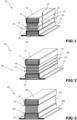
- Figure 1 shows a first embodiment of a fire protection profile system 20 with an outer profile 22 and an inner profile 24, wherein the outer profile 22 and the inner profile 24 are spaced apart from one another.
- Fire- and/or heat-resistant inserts 23, 25 are arranged in the outer profile 22 and the inner profile 24.
- the outer profile 22 and the inner profile 24 are mechanically connected to one another with one or more connecting bolts 27 spaced apart from one another, wherein the connecting bolt 27 is welded to the outer profile 22 and the inner profile 24.
- the fire protection profile system 20 has an insulator 30 which is arranged between the outer profile 22 and the inner profile 24.
- the connecting bolt 27 is drilled centrally through the insulator 30 and enables its free contraction.
- the insulator 30 is attached to the outer profile 22 on the one hand and to the inner profile 24 on the other hand with an adhesive, whereby the adhesive can withstand higher temperatures without expanding.
- the insulator 30 consists of a first insulator part 32 and a second insulator part 34 and comprises an air gap 40 as a heat transfer layer in order to create at least a reduced heat transfer or heat transport between the outer profile 22 and the inner profile 24. Since air has a low thermal conductivity and also generates heat transfer resistance, heat transfer between the outer profile 22 and the inner profile 24 is greatly reduced.
- the air gap 40 extends over the entire length of the insulator 30 parallel to the inner profile 24 and parallel to the outer profile 22.
- the insulator 30 comprises a fire- and/or heat-resistant material.
- the insulator 30 has a low emissivity coating 50 on an inner surface 37 to reduce radiant heat transfer in the event of a fire.
- the coating 50 shown comprises a zinc paint and adheres to at least one insulator 30.
- Figure 2 shows a second embodiment of a fire protection profile system 120 in building construction with the outer profile 22 and the inner profile 24 according to the embodiment of the fire protection profile system 20 from the Figure 1 , wherein the insulator 130 consists of a first insulator part 132 and a second insulator part 134 and a third insulator part 136, and wherein an air gap 140, 141 is arranged as heat transfer layers between the insulator parts 132, 134, 136.
- Figure 3 shows a third embodiment of a fire protection profile system 220 in building construction with an outer profile 222 and an inner profile 224 according to the embodiment of the fire protection profile system 20 from the Figure 1 , wherein the insulator 230 is formed in one piece and an air gap 240, 241 is present between one side of the insulator 230 and the outer profile 222 and one side of the insulator 230 and the inner profile 224.
- Figure 4 to Figure 6 show a fourth embodiment of a fire protection profile system 320 in building construction with the outer profile 22 and the inner profile 24 according to the embodiment of the fire protection profile system 20 from the Figure 1 , wherein the outer profile 22 and the inner profile 24 are spaced apart from each other.
- the insulator 330 consists of a first insulator part 332 and a second insulator part 334 and comprises a heat transfer layer 345 in order to create a reduced heat transfer or heat transport between the outer profile 22 and the inner profile 24 ( Figure 4 ) .
- the heat transfer layer 345 comprises a material that is different from the material of the at least one insulator 330.
- the heat transfer layer 345 extends over the entire length of the insulator 430 parallel to the inner profile 24 and parallel to the outer profile 22.
- the heat transfer layer 345 separates the insulator 330 into the two insulator parts 332, 334, whereby an air gap 340 is only formed in place of the heat transfer layer 345 in the event of a fire and when a threshold temperature is reached ( Figure 5 ).
- Some materials such as unfilled thermoplastic polymers such as PP or PE, are known to completely dissolve at elevated temperatures by pyrolysis or chemical degradation at a certain temperature.
- the heat transfer layer 345 comprises textile fibers. By using such materials, the shrinkage of the heat transfer layer 345 in a preferred dimension is easy to control.
- the insulator 330 has a coating 350 with low emissivity on an inner surface 337 in order to reduce the radiant heat transfer in the event of a fire.
- the coating 350 shown consists of a layer of aluminum foil which is glued to the inner surface 337 of the insulator part 332 ( Figure 6 ).
- the heat transfer layer is designed to shrink at least in the direction normal to a longitudinal extension of the insulator when the threshold temperature is reached, thus forming an air gap between the two insulator parts.
- Some materials such as calcium sulfate-based mixtures or mineral mixtures such as concrete and mortar or mixtures containing organic fibers, e.g. cellulose, are known to shrink at elevated temperatures either through chemical or physical processes such as drying or chemical decomposition and/or chemical reactions.
- the insulator has more than two insulator parts, between each of which a previously described heat transfer layer is formed.
- the heat transfer layers shrink at least in the direction normal to the longitudinal extension of the insulator and form several air gaps between the insulator parts.
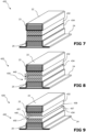
- Figure 7 to Figure 9 show a fifth embodiment of a fire protection profile system 420 with an outer profile 22 and an inner profile 24 according to the embodiment of the fire protection profile system 20 from the Figure 1 , wherein the outer profile 22 and the inner profile 24 are spaced apart from each other.
- the insulator 430 consists of a first insulator part 432 and a second insulator part 434, which originally lie firmly against each other ( Figure 7 ).
- the insulator parts 432, 434 are designed to shrink when the threshold temperature is reached, at least in the direction normal to the longitudinal extension of the insulator 430, such that an air gap 440 forms in the fire protection profile system over time ( Figure 8 ) .
- the air gap 440 forms and the heat transfer due to radiation is forced into the outside of the fire protection profile system 420, the outside in the fire protection profile system 420 receives less heat from the cause of the fire, causing the temperature on the inside to continue to rise sharply. This leads to further shrinkage of the insulator parts 432, 434. As a result, the air gap thickness will continue to increase during the fire event ( Figure 9 ).
- the insulator parts 432, 434 comprise aramid. By using such materials, the shrinkage of the insulator parts 432, 434 in the direction normal to the longitudinal extension of the insulator 430 is easy to control.
- Aluminum foils 450, 451 are glued to the inner sides 437, 438 of the insulator parts 432, 434, which provide a perforation. When heated and during shrinkage, the insulator material can release water or water vapor, which moves through the perforation to the colder side of the insulator part 432, 434 and thus reaches the surface facing the air gap 440.
- FIG 10 to Figure 13 show a further embodiment of a fire protection profile system 520, 620, 720, 820 in building construction with an outer profile 22 and an inner profile 24 according to the embodiment of the fire protection profile system 20 from the Figure 1 , whereby the heat transfer layer or the air gap in the insulators 530, 630, 730, 830 are designed differently.
- the heat transfer layer or the air gap 540 runs in a zigzag shape along the longitudinal extension of the insulator 530.
- the heat transfer layer or the air gap 640 runs triangularly along the longitudinal extension of the insulator 630.
- the heat transfer layer or the air gap 740 runs in the shape of a circular segment along the longitudinal extension of the insulator 730.
- the heat transfer layer or the air gap 840 runs trapezoidally along the longitudinal extension of the insulator 830.
- fire protection profile systems 20, 120, 220, 320, 420, 520, 620, 720, 820 are often powder coated during production, whereby the fire protection profile systems 20, 120, 220, 320, 420, 520, 620, 720, 820 are often exposed to temperatures above 150°C.
- Such fire protection profile systems comprise insulators or heat transfer layers with materials that can withstand the higher temperatures during powder coating. Therefore, in these embodiments, the aforementioned threshold temperature is greater than 200°C.
- the outer profile 22 and the inner profile 24 can be open profiles, wherein the insulators 30, 130, 230, 330, 430, 530, 630, 730, 830 can extend at least partially into the outer profile 22 and the inner profile 24.
- the outer profile 22 and the inner profile 24 can be mechanically connected to one another with one or more connecting bolts 27, as in Figure 1 disclosed.
- further connecting elements can be present in the fire protection profile systems 20, 120, 220, 320, 420, 520, 620, 720, 820 in order to mechanically connect the outer profile and the inner profile to one another and, if necessary, to hold the insulators 30, 130, 230, 330, 430, 530, 630, 730, 830 in the fire protection profile system 20, 120, 220, 320, 420, 520, 620, 720, 820.
Landscapes
- Engineering & Computer Science (AREA)
- Civil Engineering (AREA)
- Structural Engineering (AREA)
- Architecture (AREA)
- Physics & Mathematics (AREA)
- Electromagnetism (AREA)
- Building Environments (AREA)
Abstract
Die Erfindung betrifft ein Brandschutzprofilsystem 20 im Gebäudebau mit zumindest einem Aussenprofil 22 und zumindest einem Innenprofil 24, wobei das zumindest eine Aussenprofil 22 und das zumindest eine Innenprofil 24 voneinander beabstandet sind und zumindest ein Isolator 30 zwischen dem zumindest einen Aussenprofil 22 und dem zumindest einen Innenprofil 24 angeordnet ist. Der zumindest eine Isolator 30 umfasst zumindest eine Wärmeübergangsschicht 40, um zumindest einen verminderten Wärmeübergang zwischen dem zumindest einen Aussenprofil 22 und dem zumindest einen Innenprofil 24 zu schaffen. Weiters betrifft die Erfindung einen Isolator sowie den Isolator in der Verwendung in einem Brandschutzprofilsystem und ein Herstellverfahren eines Brandschutzprofilsystems.
Description
- Die vorliegende Erfindung betrifft ein Brandschutzprofilsystem gemäss dem Oberbegriff des Patentanspruchs 1, einen Isolator für ein Brandschutzprofilsystem gemäss dem Oberbegriff des Patentanspruchs 13 und die Verwendung des Isolators für ein Brandschutzprofilsystem nach Anspruch 14 sowie ein Herstellverfahren eines Brandschutzprofilsystems nach Anspruch 15.
- Bei feuerbeständigen Bauelementen wie Türen, Fassaden, Trennwänden, Fenstern, feuerbeständigen Abteilen, Brandschutzgehäusen für Kanäle, Drähte und ähnlichem im Gebäudebau werden Materialien mit einem geringen Wärmeleitung eingesetzt. Der Wärmestrom in einem Festkörper wird durch die Dichte, die spezifische Wärmekapazität und die Wärmeleitfähigkeit definiert. Der zugrundeliegende Wärmeübertragungsmechanismus wird als Wärmeleitung bezeichnet. Sehr häufig werden diese Materialien in der Fensterbauindustrie als Kühlmittel bezeichnet, ungeachtet der Tatsache, dass sie bei bestimmten Temperaturen eine negative Enthalpie aufweisen können oder auch nicht, wie z. B. 110-130 °C für physikalisch gebundenes Wasser, 140-160 °C für die Übergangsphase von Gipsanhydrit, 280-310 °C für ATH (Aluminiumtrihydroxid) und ca. 320 °C für MDH (Magnesiumdihydroxid). Neben den oben genannten gibt es noch viele weitere Materialien mit negativen Enthalpien in bestimmten Bereichen erhöhter Temperaturen. Alle diese Materialien oder eine Kombination dieser Materialien (Hybridmaterialien in Schichten oder Mischungen) haben eine gemeinsame Aufgabe: Sie verzögern die Erwärmung (oder das Aufwärmen) des zu schützenden Elements, indem sie Wärme durch endotherme Vorgänge verbrauchen, wobei die verbrauchte Wärme für den Abbau von Bindungsenergie, Reaktionsenergie, die Phasenänderung des Kühlmittels selbst usw. verwendet wird.
- Prinzipiell gibt es drei verschiedene Arten von Wärmeübertragungsmechanismen: Leitung, Strahlung und Konvektion, wobei letztere einen gewissen Massentransport in einem Fluid erfordert. Wenn Wärme von einem konvektiven Medium auf ein festes Medium übertragen wird, führt ein sogenannter Wärmeübergangswiderstand auf der Oberfläche des festen Materials zu einer zusätzlichen Wärmeübertragungsbarriere.
- Eine gängige Konstruktionsstrategie für Hochtemperaturanwendungen im Gebäudebau besteht darin, die Leistung der Wärmebarriere zu verbessern, um die Temperatur des Elements, das vor Überhitzung geschützt werden soll, bei einer bestimmten Dicke (oder geometrischen Konfiguration) des Schutzmaterials/Kühlmittels zu senken. Eine ähnliche Konstruktionsstrategie zielt darauf ab, die Dicke des Schutzmaterials zu verringern, um eine bestimmte Temperatur des zu schützenden Elements zu erreichen. Manchmal wird auch eine Kombination der oben genannten Strategien angewandt.
- Insbesondere in der Fensterindustrie werden Standardprofile mit Standardabmessungen verwendet. Am Beispiel eines Brandschutztürprofils ist es wichtig, den Temperaturanstieg auf der Nutzerseite der Tür bei einem definierten Temperaturanstieg auf der Feuerseite so weit wie möglich zu verzögern bzw. unterhalb eines gegebenen Limits zu halten. Sehr oft kann der Wärmedurchgangskoeffizient nicht ausreichend reduziert werden, um die baulichen Anforderungen zu erfüllen.
- Aus dem Stand der Technik sind
EP 1 020 608 A1 bekannt. Diese offenbart ein Verbundprofil für Rahmen von Wandelementen, Türen oder Fenstern, mit wenigstens einem Aussenprofil und einem Innenprofil, die miteinander verbunden und auf Abstand zueinander gehalten sind, wobei zwischen den Profilen ein Zwischenraum gebildet wird, in dem ein feuer- und/oder hitzebeständiges Isolationsmaterial angeordnet ist. Das Isolationsmaterial liegt satt am Aussenprofil und am Innenprofil auf und wird mittels Bolzen gehalten. - Eine Aufgabe der Erfindung besteht darin, mindestens einen der Nachteile des Standes zu vermeiden und insbesondere ein verbessertes Brandschutzprofilsystem zu schaffen, um einen alternativen Wärmetransportmechanismus in Brandschutzelementen zu nutzen. Des Weiteren soll ein verbesserter Isolator und die Verwendung des Isolators in z.B. einem Brandschutzprofilsystem geschaffen werden, sowie ein verbessertes Herstellverfahren geschaffen werden.
- Diese Aufgabe wird durch die Merkmale der unabhängigen Patentansprüche gelöst. Vorteilhafte Weiterbildungen sind in den Figuren und in den abhängigen Patentansprüchen dargelegt.
- Ein erfindungsgemässes Brandschutzprofilsystem im Gebäudebau umfasst zumindest ein Aussenprofil und zumindest ein Innenprofil, wobei das zumindest eine Aussenprofil und das zumindest eine Innenprofil voneinander beabstandet sind, und umfasst zumindest einen Isolator, welcher zwischen dem zumindest einen Aussenprofil und dem zumindest einen Innenprofil angeordnet ist. Der zumindest eine Isolator umfasst zumindest eine Wärmeübergangsschicht, um zumindest einen verminderten Wärmeübergang zwischen dem zumindest einen Aussenprofil und dem zumindest einen Innenprofil zu schaffen.
- Das vorliegende Brandschutzprofilsystem stellt ein neues Mittel zur Verfügung, um den Wärmetransport im Gebäudebau, beispielsweise in Brandschutzelementen wie Feuerschutzabschlüsse, Trennwände und dgl., durch das Einbringen von mindestens einer oder mehrerer Wärmeübergangsschichten zu reduzieren und damit eine Ausbreitung der Wärme im Brandfall entgegenzuwirken. Eine Wärmeübergangsschicht ist definiert durch den Übergang von der Wärmeleitung in einem Festkörper zur Wärmeübertragung durch Strahlung in die Umgebung und insbesondere in Kombination mit Konvektion. Im allgemeinen Fall ist ein Wärmeübergang die Wärmeübertragung zwischen der Oberfläche eines Festkörpers und einem bewegten Fluid oder einem Gas. Dabei werden zusätzlich Wärmeübergangswiderstände aktiviert. Die offenbarte Lösung bietet im Vergleich zur bekannten Verwendung von Materialien mit einer geringen thermischen Diffusivität bei Brandschutzprofilsystem einen wesentlichen Vorteil in der Brandbekämpfung in Gebäudebauten. Der zumindest eine Isolator umfasst zumindest ein feuer- und/oder hitzebeständiges Material. Zusätzlich kann zumindest das Aussenprofil ein feuer- und/oder hitzebeständiges Material aufweisen und alternativ oder ergänzend das Innenprofil ein feuer- und/oder hitzebeständiges Material aufweisen. Das Aussenprofil und gegebenenfalls auch das Innenprofil können auf zumindest einer Profilseite offen ausgebildet sein, sodass sich der zumindest eine Isolator zumindest teilweise in die Profile hinein erstreckt, wenn dieser zwischen den Profilen angeordnet ist.
- Allgemein ist ein Wärmetransport der Transport von Energie in Form von Wärme über mindestens eine thermodynamische Systemgrenze hinweg. Es gibt drei Arten von Wärmetransportvorgängen, nämlich durch mechanische Berührung, Konvektion, das Mitführen thermischer Energie in einem strömenden Medium, sowie Wärmestrahlung, also elektromagnetische Wellen. Ein derartiger Wärmetransport kann im vorliegenden Brandschutzprofilsystem verbessert verhindert werden.
- Bevorzugterweise ist die zumindest eine Wärmeübergangsschicht ein Luftspalt. Da Luft eine geringe Wärmeleitfähigkeit aufweist und zudem Wärmeübergangswiderstände generiert, ist eine Wärmeübertragung zwischen dem zumindest einen Aussenprofil und dem zumindest einen Innenprofil stark reduziert. Zudem dominiert bei höheren Temperaturen die Wärmeübertragung durch Strahlung über den Luftspalt. Der Luftspalt erstreckt sich bevorzugt in Richtung normal zu einer Längsausstreckung des Isolators und weist eine Luftspaltdicke von zumindest 5% der Dicke des zumindest einen Isolators auf und weist bevorzugt eine Mindestdicke von 0.5 mm auf. Damit ist ein für die Brandbekämpfung ausreichend dimensionierter Luftspalt vorhanden und ein effizienter verminderter Wärmeübergang erreicht.
- Alternativ oder ergänzend ist der zumindest eine Isolator zwischen dem zumindest einen Aussenprofil und dem zumindest einen Innenprofil derart angeordnet, dass dieser zumindest vom zumindest einen Aussenprofil oder vom zumindest einen Innenprofil beabstandet ist, sodass sich zwischen dem zumindest einen Aussenprofil und dem zumindest einen Isolator oder zwischen dem zumindest einen Innenprofil und dem zumindest einen Isolator zumindest ein Luftspalt als Wärmeübergangsschicht ausbildet. Dabei kann der zumindest eine Isolator einstückig ausgebildet sein und mittels Abstandelemente vom zumindest einen Aussenprofil oder vom zumindest vom zumindest einen Innenprofil separiert sein. Dies erlaubt eine einfache Herstellung des Brandschutzprofilsystem.
- Insbesondere erstreckt sich der Luftspalt im Wesentlichen parallel zum zumindest einen Innenprofil und alternativ oder ergänzend parallel zum zumindest einen Aussenprofil und vorteilhaft über die gesamte Länge des zumindest einen Isolators. Damit besteht der zumindest eine Isolator aus zumindest zwei getrennte und voneinander beabstandete Isolatorteile, wobei beide Isolatorteile bei der Herstellung des Brandschutzprofilsystems derart zwischen dem zumindest einen Aussenprofil und dem zumindest einen Innenprofil angeordnet werden, dass zwischen ihnen zumindest eine Luftspalt vorhanden ist.
- Bevorzugt weist der zumindest eine Isolator zumindest eine weitere Wärmeübergangsschicht auf, welche insbesondere als weiterer Luftspalt ausgebildet ist. Damit ist zumindest ein weiterer verminderter Wärmeübergang zwischen dem zumindest einen Aussenprofil und dem zumindest einen Innenprofil geschaffen, sodass die Wärmeübertragung verbessert unterbunden wird.
- Vorzugsweise trennt die zumindest eine Wärmeübergangsschicht den Isolator beim Erreichen einer Schwelltemperatur zumindest bereichsweise in zumindest zwei Isolatorteile. Damit bildet sich erst im Brandfall ein Luftspalt aus. In einem solchen Fall wird das Brandschutzprofilsystem von der Feuerseite her erhitzt, was zu einem vorübergehend erhöhen Temperaturzustand im zumindest einen Isolator führt.
- Insbesondere umfasst die zumindest eine Wärmeübergangsschicht ein Material, dass unterschiedlich zum Material des zumindest einen Isolators ist. Von einigen Materialien wie z.B. ungefüllte thermoplastische Polymere wie PP oder PE ist bekannt, dass sie bei erhöhten Temperaturen durch Pyrolyse oder chemischen Abbau bei einer bestimmten Temperatur vollständig auflösen.
- Bevorzugterweise ist die zumindest eine Wärmeübergangsschicht ausgebildet, beim Erreichen der Schwelltemperatur sich zumindest in Richtung normal zu einer Längsausstreckung des Isolators zu verformen. Von einigen Materialien, wie z.B. auf Calciumsulfat basierenden Gemischen oder mineralischen Gemischen wie, Beton, Mörtel oder Gemischen, die organische Fasern, z.B. Zellulose enthalten, ist bekannt, dass sie bei erhöhten Temperaturen entweder durch chemische oder physikalische Prozesse wie Trocknung oder chemische Zersetzung und/oder chemische Reaktionen schrumpfen.
- Insbesondere ist die zumindest eine Wärmeübergangsschicht ausgebildet, beim Erreichen der Schwelltemperatur sich zumindest in Richtung normal zu einer Längsausstreckung des Isolators zu verformen, dass sich zumindest ein Luftspalt zwischen den zumindest zwei Isolatorteilen bildet.
- Vorzugsweise ist zumindest einer der Isolatorteile ausgebildet, sich beim Erreichen der Schwelltemperatur zumindest in Richtung normal zu einer Längsausstreckung des Isolators derart zu verformen, dass sich zumindest ein Luftspalt im Brandschutzprofilsystem bildet. Angenommen ein Brandfall startet im Bereich des Innenprofils und das Aussenprofil ist der Brandursache abgewandt: Wenn sich der Luftspalt bildet und die Wärmeübertragung aufgrund der Strahlung in die Aussenseite des Brandschutzprofilsystems gezwungen wird, erhält die Aussenseite im Brandschutzprofilsystem weniger Wärme von der Brandursache, wodurch die Temperatur auf der Innenseite weiter stark ansteigt. Dies führt zu einer weiteren Schrumpfung des zumindest einen Isolatorteils oder der zumindest einen Wärmeübergangsschicht. Infolgedessen wird sich die Luftspaltdicke während des Brandereignisses weiter vergrössern. Dies ermöglicht eine stabil funktionierende thermischen Trennung im Brandschutzprofilsystem.
- Bevorzugterweise ist die Schwelltemperatur grösser 90 °C. Damit kann ein Material wie z.B. gipshaltige Gemische für die Wärmeübergangsschicht oder dem zumindest einen Isolator verwendet werden, das unter Betriebsbedingungen, einschließlich eines vorübergehenden Temperaturanstiegs ausreichend stabil ist. Derartige Materialien sind gut lagerbar, ohne dass sie Ihre Form verändern.
- Bevorzugt ist die Schwelltemperatur grösser 200°C. Damit kann ein Material, wie z.B. modifizierte Gipsgemische umfassend Anhydrit in verschiedenen Phasen, eingesetzt werden, das unter Betriebsbedingungen, einschließlich eines vorübergehenden Temperaturanstiegs, dem ein Brandschutzprofilsystem beispielsweise während der Pulverbeschichtung ausgesetzt ist, ausreichend stabil ist. Daher sollte bei der Festlegung des Materials für die Wärmeübergangsschicht, oder für den zumindest einen Isolator, die gewünschte Schrumpfung erst bei etwa 200 °C beginnen. In Anbetracht einer bevorzugten geometrischen Konfiguration des Brandschutzprofilsystems ist es daher vorteilhaft, die Schrumpfung so zu steuern, dass diese hauptsächliche in Richtung normal zu einer Längsausstreckung des Isolators erfolgt.
- Vorzugsweise umfasst das Material der zumindest einen Wärmeübergangsschicht oder des zumindest einen Isolators zumindest Textilfasern oder Fasern aus Glas, Metall oder Aramid. Mit der Verwendung derartiger Materialien ist das Schrumpfen des zumindest einen Isolators oder der Wärmeübergangsschicht in einer bevorzugten Dimension einfach zu kontrollieren und eine mechanische Verstärkung der zumindest einen Wärmeübergangsschicht oder des zumindest einen Isolators möglich, insbesondere mit gerichteten langen oder kurzen Textilfasern und anderen ähnlichen Materialien. In einer solchen Konfiguration behält der Luftspalt seine Dimensionen auch bei strukturellen Belastungen wie Biegung oder Torsion bei.
- Bevorzugterweise ist zumindest eine Beschichtung mit geringer Emissivität im Isolator vorhanden, um die Strahlungswärmeübertragung im Brandfall zu verringern. Eine Beschichtung kann auch eine Schicht wie eine Folie umfassen, welche am Isolator angeordnet ist, oder in welcher der Isolator angeordnet ist. Insbesondere ist zumindest eine Metallbeschichtung im Isolator vorhanden. Diese würde eine billige, gut funktionierende Lösung sein, um die Strahlungswärmeübertragung im Brandfall zu verringern. Eine leicht erhältliche Lösung besteht aus mindestens einer Schicht Aluminiumfolie. Je nach Anwendung kann es sich auch um eine beliebige Beschichtung mit niedrigem Emissionsgrad handeln, z. B. Kupferfolie, Nickelfolie, Stahlfolie oder sogar Titanfolie. Nichtmetallische Folien mit niedrigem Emissionsgrad wie Mylar, Kapton oder ähnliche Folien können ebenfalls verwendet werden. In Fällen, in denen eine Folie verwendet wird, kann diese auf die Isolatorflächen geklebt oder durch Quetschen oder durch eine andere mechanische oder chemische Verbindung fixiert werden.
- Vorzugsweise ist die zumindest eine Beschichtung zumindest an einer Seite der zumindest einen Wärmeübergangsschicht angeordnet. Eine einfach herstellbare Lösung besteht aus einer Beschichtung an der zum Luftspalt hingerichtete Seite des zumindest einen Isolators. Beispielsweise kann die Beschichtung eine Farbe, wie beispielsweise eine Zinkfarbe umfassen.
- Insbesondere haftet die zumindest eine Beschichtung am zumindest einen Isolator, sodass sie sich im Brandfall nicht vom zumindest einen Isolator ablösen kann.
- Bevorzugterweise weist die Wärmeübergangsschicht an der Oberseite und der Unterseite eine Beschichtung auf. Damit sind an beiden Seiten im Luftspalt Beschichtungen angeordnet, sodass die Strahlungswärmeübertragung im Brandfall weiter verringert wird.
- Vorzugsweise weist die zumindest eine Beschichtung eine Perforierung auf. Es ist möglich, dass das Isoliermaterial beim Erhitzen und während seiner Schrumpfung Wasser oder Wasserdampf abgibt. Dieses Wasser könnte sich zur kälteren Seite des Isolators hinbewegen und derart die dem Luftspalt zugewandte Oberfläche erreichen und dort kondensieren oder sich akkumulieren. Um dies zu verhindern, können perforierte Beschichtungen verwendet werden, durch die Feuchtigkeit hindurchdringen kann, ohne sich hinter der Beschichtung zu sammeln. Die Ansammlung von Wassertropfen oder heißem Dampf im Inneren der thermischen Trennung sollte die Leistung der thermischen Trennung selbst nicht beeinträchtigen. Bevorzugt gibt der Isolator beim Erreichen der Schwelltemperatur Wasserdampf ab.
- Bevorzugterweise ist der zumindest eine Isolator mit dem zumindest einen Aussenprofil verbunden. Damit ist der zumindest eine Isolator stabil an dem Aussenprofil fixiert. Insbesondere ist der Isolator mit einer formstabilen Verbindung mit dem zumindest einen Aussenprofil verbunden. Damit kann ein Ablösen des zumindest einen Isolators vom Aussenprofil verhindert werden. Bevorzugt ist der zumindest eine Isolator am Aussenprofil mit einem Klebstoff befestigt, wobei der Klebstoff höheren Temperaturen ohne Ausdehnung standhält. Damit ist der zumindest eine Isolator gezwungen, sich an der gewünschten Stelle zu öffnen und in Richtung des Aussenprofils zu schrumpfen.
- Alternativ oder ergänzend ist der Isolator mit dem zumindest einen Innenprofil verbunden. Damit ist der zumindest eine Isolator stabil an dem Innenprofil fixiert. Insbesondere ist der Isolator mit einer formstabilen Verbindung mit dem zumindest einen Innenprofil verbunden. Damit kann ein Ablösen des zumindest einen Isolators vom Innenprofil verhindert werden. Bevorzugt ist der zumindest eine Isolator am Innenprofil mit einem Klebstoff befestigt, wobei der Klebstoff höheren Temperaturen ohne Ausdehnung standhält. Damit ist der zumindest eine Isolator gezwungen, sich an der gewünschten Stelle zu öffnen und in Richtung des Innenprofils zu schrumpfen.
- Vorzugsweise ist zwischen dem zumindest einen Aussenprofil und dem zumindest einen Innenprofil zumindest ein Verbindungselement zum formstabilen Zusammenwirken des Brandschutzprofilsystem vorhanden, damit ist die Integrität und die Stabilität des Brandschutzprofilsystems bewahrt. Eine solche Verbindung kann z. B. durch einzelne Verbindungsbolzen mit vordefiniertem Abstand erreicht werden, die beispielsweise am Aussenprofil geschweisst werden und zentral durch den zumindest einen Isolator gebohrt werden und dessen freie Kontraktion ermöglichen.
- Ein erfindungsgemässer Isolator weist zumindest eine Wärmeübergangsschicht auf, um zumindest einen verminderten Wärmeübergang zwischen zumindest einem Aussenprofil und zumindest einem Innenprofil zu schaffen. Der Isolator stellt ein neues Mittel zur Verfügung, um den Wärmetransport im Gebäudebau, beispielsweise in Brandschutzelementen wie Feuerschutzabschlüsse, Trennwände und dgl., durch das Einbringen von mindestens einer oder mehrerer Wärmeübergangsschichten zu reduzieren und damit eine Ausbreitung der Wärme im Brandfall entgegenzuwirken.
- Alternative Anwendungen für einen erfindungsgemässen Isolator sind z.B. Brandschutzabkofferungen bzw. Füllungen für Brandschutzelemente wie z.B. Trennwände sowie Schutz von Lüftungskanälen und Rohre.
- Weiters ist eine erfindungsgemäss Verwendung eines Isolators für ein Brandschutzprofilsystem in einem Profilsystem für den Gebäudebau offenbart. Dazu zählen auch Verwendungen als Brandschutzabkofferungen bzw. Füllungen für Brandschutzelemente wie z.B. Trennwände sowie Schutz von Lüftungskanälen und Rohre.
- Ein erfindungsgemässes Herstellverfahren eines Brandschutzprofilsystems umfasst zumindest die folgenden Schritte:
- a. Bereitstellen zumindest eines Innenprofils und eines Aussenprofils;
- b. Anordnen zumindest eines Isolators zwischen dem Innenprofil und dem Aussenprofil, wobei der zumindest eine Isolator zumindest eine Wärmeübergangsschicht umfasst und/oder der zumindest eine Isolator zwischen dem zumindest einen Aussenprofil und dem zumindest einen Innenprofil derart angeordnet wird, dass der zumindest eine Isolator zumindest vom zumindest einen Aussenprofil oder vom zumindest einen Innenprofil beabstandet ist, sodass sich dazwischen ein Luftspalt als Wärmeübergangsschicht ausbildet.
- Mit diesem Herstellverfahren wird ein neues Brandschutzprofilsystem zur Verfügung gestellt, um den Wärmetransport im Gebäudebau, beispielsweise in Brandschutzelementen wir Feuerschutzabschlüsse, Trennwände und dgl., durch das Einbringen von mindestens einer oder mehrerer Wärmeübergangsschichten zu reduzieren und damit eine Ausbreitung der Wärme im Brandfall entgegenzuwirken. Die offenbarte Lösung bietet im Vergleich zur bekannten Verwendung von Materialien mit einer geringen thermischen Diffusivität bei Brandschutzprofilsystem einen wesentlichen Vorteil in der Brandbekämpfung in Gebäudebauten.
- Das Aussenprofil und gegebenenfalls auch das Innenprofil können auf zumindest einer Profilseite offen ausgebildet sein, sodass sich der zumindest eine Isolator zumindest teilweise in die Profile erstreckt, wenn dieser zwischen den Profilen angeordnet ist.
- Weitere Vorteile, Merkmale und Einzelheiten der Erfindung ergeben sich aus der nachfolgenden Beschreibung, in der unter Bezugnahme auf die Zeichnungen Ausführungsbeispiele der Erfindung beschrieben sind.
- Die Bezugszeichenliste ist wie auch der technische Inhalt der Patentansprüche und Figuren Bestandteil der Offenbarung. Die Figuren werden zusammenhängend und übergreifend beschrieben. Gleiche Bezugszeichen bedeuten gleiche Bauteile, Bezugszeichen mit unterschiedlichen Indices geben funktionsgleiche oder ähnliche Bauteile an.
- Mittels der nachfolgenden Figuren wird anhand von Ausführungsbeispielen die Erfindung näher erläutert. Die Bezugszeichenliste ist Bestandteil der Offenbarung.
- Positionsangaben, wie "oben", unten", "rechts" oder "links" sind jeweils auf die entsprechenden Darstellungen bezogen und sind nicht als einschränkend zu verstehen.
- Obwohl die Erfindung mittels der Figuren und der zugehörigen Beschreibung dargestellt und detailliert beschrieben ist, sind diese Darstellung und diese detaillierte Beschreibung illustrativ und beispielhaft zu verstehen und nicht als die Erfindung einschränkend. Es versteht sich, dass Fachleute Änderungen und Abwandlungen machen können, ohne den Umfang der folgenden Ansprüche zu verlassen. Insbesondere umfasst die Erfindung ebenfalls Ausführungsformen mit jeglicher Kombination von Merkmalen, die vorstehend zu verschiedenen Aspekten und/oder Ausführungsformen genannt oder gezeigt sind.
- Die Erfindung umfasst ebenfalls einzelne Merkmale in den Figuren, auch wenn sie dort im Zusammenhang mit anderen Merkmalen gezeigt sind und/oder vorstehend nicht genannt sind. Im Weiteren schliesst der Ausdruck "umfassen" und Ableitungen davon andere Elemente oder Schritte nicht aus. Ebenfalls schliesst der unbestimmte Artikel "ein" beziehungsweise "eine" und Ableitungen davon eine Vielzahl nicht aus. Die Funktionen mehrerer in den Ansprüchen aufgeführter Merkmale können durch eine Einheit erfüllt sein. Die Begriffe "im Wesentlichen", "etwa", "ungefähr" und dergleichen in Verbindung mit einer Eigenschaft beziehungsweise einem Wert definieren insbesondere auch genau die Eigenschaft beziehungsweise genau den Wert. Alle Bezugszeichen in den Ansprüchen sind nicht als den Umfang der Ansprüche einschränkend zu verstehen.
- Die Figuren werden zusammenhängend und übergreifend beschrieben. Gleiche Bezugszeichen bedeuten gleiche Bauteile. Es zeigen
-
Fig. 1 : eine erste Ausführungsform des erfindungsgemässen Brandschutzprofilsystems mit einem Luftspalt in einem Isolator als eine Wärmeübergangsschicht in einer perspektivischen Ansicht, -
Fig. 2 : eine zweite Ausführungsform des erfindungsgemässen Brandschutzprofilsystems mit zwei Luftspalte in einem Isolator als Wärmeübergangsschichten in einer perspektivischen Ansicht, -
Fig. 3 : eine dritte Ausführungsform des erfindungsgemässen Brandschutzprofilsystems mit zwei Luftspalte als Wärmeübergangsschichten, welche benachbart zum Innenprofil und zum Aussenprofil des Brandschutzprofilsystems angeordnet sind in einer perspektivischen Ansicht, -
Fig. 4 : eine vierte Ausführungsform des erfindungsgemässen Brandschutzprofilsystems mit einer Wärmeübergangsschicht in einem Isolator in einer perspektivischen Ansicht, -
Fig. 5 : das Brandschutzprofilsystem gemässFig. 4 ohne der Wärmeübergangsschicht im Isolator in einer perspektivischen Ansicht, -
Fig. 6 : einen Ausschnitt des Brandschutzprofilsystems gemässFig. 5 ohne der Wärmeübergangsschicht im Isolator in einer perspektivischen Ansicht, -
Fig. 7 bis Fig. 9 : eine fünfte Ausführungsform des erfindungsgemässen Brandschutzprofilsystems mit einem zweiteiligen Isolator, welcher im Brandfall seine Ausdehnung normal zur Längsausrichtung des Isolators verringert, in einer perspektivischen Ansicht, und -
Fig. 10 bis Fig. 13 : weitere Ausführungsformen des erfindungsgemässen Brandschutzprofilsystems mit unterschiedlichen Ausgestaltungen der Wärmeübergangsschicht in einer perspektivischen Ansicht. -
Figur 1 zeigt eine erste Ausführungsform eines Brandschutzprofilsystems 20 mit einem Aussenprofil 22 und einem Innenprofil 24, wobei das Aussenprofil 22 und das Innenprofil 24 voneinander beabstandet sind. Im Aussenprofil 22 und im Innenprofil 24 sind feuer- und/oder hitzebeständiges Einschieblinge 23, 25 angeordnet. Das Aussenprofil 22 und das Innenprofil 24 sind mechanisch mit einem oder mehreren voneinander beabstandeten Verbindungsbolzen 27 miteinander verbunden, wobei der Verbindungsbolzen 27 am Aussenprofil 22 und am Innenprofile 24 angeschweisst ist. Das Brandschutzprofilsystem 20 weist einen Isolator 30 auf, welcher zwischen dem Aussenprofil 22 und dem Innenprofil 24 angeordnet ist. Der Verbindungsbolzen 27 ist zentral durch den Isolator 30 gebohrt und ermöglicht dessen freie Kontraktion. Der Isolator 30 ist einerseits am Aussenprofil 22 und andererseits am Innenprofil 24 mit einem Klebstoff befestigt, wobei der Klebstoff höheren Temperaturen ohne Ausdehnung standhält. - Der Isolator 30 besteht aus einem ersten Isolatorteil 32 und einem zweiten Isolatorteil 34 und umfasst einen Luftspalt 40 als Wärmeübergangsschicht, um zumindest einen verminderten Wärmeübergang bzw. Wärmetransport zwischen dem Aussenprofil 22 und dem Innenprofil 24 zu schaffen. Da Luft eine geringe Wärmeleitfähigkeit aufweist und zudem Wärmeübergangswiderstände generiert, ist eine Wärmeübertragung zwischen dem Aussenprofil 22 und dem Innenprofil 24 stark reduziert. Der Luftspalt 40 erstreckt sich über die gesamte Länge des Isolators 30 parallel zum Innenprofil 24 sowie parallel zum Aussenprofil 22. Der Isolator 30 umfasst ein feuer- und/oder hitzebeständiges Material.
- Der Isolator 30 weist auf einer Innenfläche 37 eine Beschichtung 50 mit geringer Emissivität auf, um die Strahlungswärmeübertragung im Brandfall zu verringern. Die gezeigte Beschichtung 50 umfasst eine Zinkfarbe und haftet am zumindest einen Isolator 30.
-
Figur 2 zeigt eine zweite Ausführungsform eines Brandschutzprofilsystems 120 im Gebäudebau mit dem Aussenprofil 22 und dem Innenprofil 24 gemäss der Ausführungsform des Brandschutzprofilsystems 20 aus derFigur 1 , wobei der Isolator 130 aus einem ersten Isolatorteil 132 und einem zweiten Isolatorteil 134 sowie einem dritten Isolatorteil 136 besteht, und wobei jeweils ein Luftspalt 140, 141 als Wärmeübergangsschichten zwischen den Isolatorteilen 132, 134, 136 angeordnet sind. -
Figur 3 zeigt eine dritte Ausführungsform eines Brandschutzprofilsystems 220 im Gebäudebau mit einem Aussenprofil 222 und einem Innenprofil 224 gemäss der Ausführungsform des Brandschutzprofilsystems 20 aus derFigur 1 , wobei der Isolator 230 einstückig ausgebildet ist und jeweils ein Luftspalt 240, 241 zwischen einer Seite des Isolators 230 und dem Aussenprofil 222 sowie einer Seite des Isolators 230 und dem Innenprofil 224 vorhanden sind. -
Figur 4 bis Figur 6 zeigen eine vierte Ausführungsform eines Brandschutzprofilsystems 320 im Gebäudebau mit dem Aussenprofil 22 und dem Innenprofil 24 gemäss der Ausführungsform des Brandschutzprofilsystems 20 aus derFigur 1 , wobei das Aussenprofil 22 und das Innenprofil 24 voneinander beabstandet sind. - Der Isolator 330 besteht aus einem ersten Isolatorteil 332 und einem zweiten Isolatorteil 334 und umfasst eine Wärmeübergangsschicht 345, um einen verminderten Wärmeübergang bzw. Wärmetransport zwischen dem Aussenprofil 22 und dem Innenprofil 24 zu schaffen (
Figur 4 ). In dieser Ausführungsform umfasst die Wärmeübergangsschicht 345 ein Material, dass unterschiedlich zum Material des zumindest einen Isolators 330 ist. Die Wärmeübergangsschicht 345 erstreckt sich über die gesamte Länge des Isolators 430 parallel zum Innenprofil 24 und parallel zum Aussenprofil 22. Die Wärmeübergangsschicht 345 trennt den Isolator 330 in die zwei Isolatorteile 332, 334, wobei sich erst im Brandfall, und beim Erreichen einer Schwelltemperatur, ein Luftspalt 340 anstelle der Wärmeübergangsschicht 345 ausbildet (Figur 5 ). Von einigen Materialien wie z.B. ungefüllte thermoplastische Polymere wie PP oder PE ist bekannt, dass sie bei erhöhten Temperaturen durch Pyrolyse oder chemischen Abbau bei einer bestimmten Temperatur vollständig auflösen. Die Wärmeübergangsschicht 345 weist Textilfasern auf. Mit der Verwendung derartiger Materialien ist das Schrumpfen der Wärmeübergangsschicht 345 in einer bevorzugten Dimension einfach zu kontrollieren. - Der Isolator 330 weist in dieser Ausführungsform an einer Innenfläche 337 eine Beschichtung 350 mit geringer Emissivität auf, um die Strahlungswärmeübertragung im Brandfall zu verringern. Die gezeigte Beschichtung 350 besteht aus einer Schicht Aluminiumfolie, die auf die Innenfläche 337 des Isolatorteils 332 geklebt ist (
Figur 6 ). - In einer alternativen Ausführungsform ist die Wärmeübergangsschicht ausgebildet, beim Erreichen der Schwelltemperatur zumindest in Richtung normal zu einer Längsausstreckung des Isolators zu schrumpfen und somit einen Luftspalt zwischen den zwei Isolatorteilen auszubilden. Von einigen Materialien, wie z.B. auf Calciumsulfat basierenden Gemischen oder mineralischen Gemischen wie, Beton und Mörtel oder Gemischen, die organische Fasern, z.B. Zellulose enthalten, ist bekannt, dass sie bei erhöhten Temperaturen entweder durch chemische oder physikalische Prozesse wie Trocknung oder chemische Zersetzung und/oder chemische Reaktionen schrumpfen.
- In einer alternativen Ausführungsform weist der Isolator mehr als zwei Isolatorteile auf, zwischen denen jeweils eine zuvor beschriebene Wärmeübergangsschicht ausgebildet ist. Beim Erreichen der Schwelltemperatur schrumpfen die Wärmeübergangsschichten zumindest in Richtung normal zu der Längsausstreckung des Isolators und bilden mehrere Luftspalte zwischen den Isolatorteilen aus.
-
Figur 7 bis Figur 9 zeigen eine fünfte Ausführungsform eines Brandschutzprofilsystems 420 mit einem Aussenprofil 22 und einem Innenprofil 24 gemäss der Ausführungsform des Brandschutzprofilsystems 20 aus derFigur 1 , wobei das Aussenprofil 22 und das Innenprofil 24 voneinander beabstandet sind. - Der Isolator 430 besteht aus einem ersten Isolatorteil 432 und einem zweiten Isolatorteil 434, welche ursprünglich fest aneinander anliegen (
Figur 7 ). Die Isolatorteile 432, 434 sind ausgebildet, sich beim Erreichen der Schwelltemperatur zumindest in Richtung normal zu der Längsausstreckung des Isolators 430 derart schrumpfen, dass sich mit der Zeit ein Luftspalt 440 im Brandschutzprofilsystem bildet (Figur 8 ). Wenn sich der Luftspalt 440 bildet und die Wärmeübertragung aufgrund der Strahlung in die Aussenseite des Brandschutzprofilsystems 420 gezwungen wird, erhält die Aussenseite im Brandschutzprofilsystem 420 weniger Wärme von der Brandursache, wodurch die Temperatur auf der Innenseite weiter stark ansteigt. Dies führt zu einer weiteren Schrumpfung der Isolatorteile 432, 434. Infolgedessen wird sich die Luftspaltdicke während des Brandereignisses weiter vergrössern (Figur 9 ). - Die Isolatorteile 432, 434 weisen Aramid auf. Mit der Verwendung derartiger Materialien ist das Schrumpfen der Isolatorteile 432, 434 in Richtung normal zu der Längsausstreckung des Isolators 430 einfach zu kontrollieren. An den Innenseiten 437, 438 der Isolatorteile 432, 434 sind Aluminiumfolien 450, 451 angeklebt, welche eine Perforierung aufweisen. Das Isolatormaterial kann beim Erhitzen und während dem Schrumpfung Wasser oder Wasserdampf abgeben, welches durch die Perforierung zur kälteren Seite des Isolatorteils 432, 434 hinbewegt und derart die dem Luftspalt 440 zugewandte Oberfläche erreicht.
-
Figur 10 bis Figur 13 zeigen eine weitere Ausführungsform eines Brandschutzprofilsystems 520, 620, 720, 820 im Gebäudebau mit einem Aussenprofil 22 und einem Innenprofil 24 gemäss der Ausführungsform des Brandschutzprofilsystems 20 aus derFigur 1 , wobei die Wärmeübergangsschicht bzw. der Luftspalt in den Isolatoren 530, 630, 730, 830 unterschiedliche ausgestaltet sind. InFigur 10 verläuft die Wärmeübergangsschicht bzw. der Luftspalt 540 zickzack-förmig entlang der Längsausstreckung des Isolators 530. InFigur 11 verläuft die Wärmeübergangsschicht bzw. der Luftspalt 640 dreieck-förmig entlang der Längsausstreckung des Isolators 630. InFigur 12 verläuft die Wärmeübergangsschicht bzw. der Luftspalt 740 kreissegment-förmig entlang der Längsausstreckung des Isolators 730. InFigur 13 verläuft die Wärmeübergangsschicht bzw. der Luftspalt 840 trapez-förmig entlang der Längsausstreckung des Isolators 830. - Die zuvor genannten Brandschutzprofilsysteme 20, 120, 220, 320, 420, 520, 620, 720, 820 gemäss den
Figuren 1 bis 13 werden bei der Herstellung oftmals pulverbeschichtet, wobei die Brandschutzprofilsysteme 20, 120, 220, 320, 420, 520, 620, 720, 820 oftmals Temperaturen über 150°C ausgesetzt sind. Derartige Brandschutzprofilsysteme umfassen Isolatoren bzw. Wärmeübergangsschichten mit Materiealien, welche den höheren Temperaturen beim Pulverbeschichten widerstehen können. Daher ist bei diesen Ausführungsformen die zuvor genannte Schwelltemperatur grösser 200°C. - Bei den zuvor genannten Brandschutzprofilsystemen 20, 120, 220, 320, 420, 520, 620, 720, 820 gemäss den
Figuren 1 bis 13 ohne Herstellungsschritte mit erhöhten Temperaturen können Materialien verwendet werden, mit einer Schwelltemperatur grösser 90 °C. - Bei den zuvor genannten Brandschutzprofilsystemen 20, 120, 220, 320, 420, 520, 620, 720, 820 gemäss den
Figuren 1 bis 13 können auch mehrere Beschichtungen 50, 450, 550 an den Isolatoren 30, 130, 230, 330, 430, 530, 630, 730, 830 oder den Wärmeübergangsschichten angeordnet sein. - Bei den zuvor genannten Brandschutzprofilsystemen 20, 120, 220, 320, 420, 520, 620, 720, 820 gemäss den
Figuren 1 bis 13 können das Aussenprofil 22 und das Innenprofil 24 offene Profile sein, wobei die Isolatoren 30, 130, 230, 330, 430, 530, 630, 730, 830 sich zumindest abschnittsweise in das Aussenprofil 22 und das Innenprofil 24 hinein erstrecken können. - Bei den zuvor genannten Brandschutzprofilsystemen 120, 220, 320, 420, 520, 620, 720, 820 gemäss den
Figuren 1 bis 13 können das Aussenprofil 22 und das Innenprofil 24 mechanisch mit einem oder mehreren Verbindungsbolzen 27 miteinander verbunden sein, wie inFigur 1 offenbart. Alternativ können weitere Verbindungselemente in den Brandschutzprofilsystemen 20, 120, 220, 320, 420, 520, 620, 720, 820 vorhanden sein, um das Aussenprofil und das Innenprofil mechanisch miteinander zu verbinden und gegebenenfalls die Isolatoren 30, 130, 230, 330, 430, 530, 630, 730, 830 im Brandschutzprofilsystem 20, 120, 220, 320, 420, 520, 620, 720, 820 zu halten. - Ein Herstellverfahren eines Brandschutzprofilsystems 20, 120, 220, 320, 420, 520, 620, 720, 820 gemäss den
Figuren 1 bis 13 umfasst zumindest die folgenden Schritte, wobei die Reihenfolge der Schritte variieren kann: - a. Bereitstellen zumindest eines Innenprofils und eines Aussenprofils;
- b. Anordnen zumindest eines Isolators zwischen dem Innenprofil und dem Aussenprofil, wobei der zumindest eine Isolator zumindest eine Wärmeübergangsschicht umfasst und/oder der zumindest eine Isolator zwischen dem zumindest einen Aussenprofil und dem zumindest einen Innenprofil derart angeordnet wird, dass der zumindest eine Isolator zumindest vom zumindest einen Aussenprofil oder vom zumindest einen Innenprofil beabstandet ist, sodass sich dazwischen ein Luftspalt als Wärmeübergangsschicht ausbildet.
- c. Im Bereich der Wärmeübergangsschicht an der Innenfläche des Isolators eine Beschichtung angeordnet wird.
- d. Das Aussenprofil und das Innenprofil mit mehreren Verbindungsbolzen verbunden werden.
-
- 20
- Brandschutzprofilsystem
- 22
- Aussenprofil
- 23
- Einschiebling/Masse
- 24
- Innenprofil
- 25
- Einschiebling/Masse
- 27
- Verbindungsbolzen
- 30
- Isolator
- 32
- erster Isolatorteil
- 34
- zweiter Isolatorteil
- 37
- Innenfläche von 34
- 40
- Luftspalt
- 50
- Beschichtung
- 120
- Brandschutzprofilsystem
- 130
- Isolator
- 132
- erster Isolatorteil
- 134
- zweiter Isolatorteil
- 136
- dritter Isolatorteil
- 140
- Luftspalt
- 141
- Luftspalt
- 220
- Brandschutzprofilsystem
- 222
- Aussenprofil
- 224
- Innenprofil
- 230
- Isolator
- 240
- Luftspalt
- 241
- Luftspalt
- 320
- Brandschutzprofilsystem
- 330
- Isolator
- 332
- erster Isolatorteil
- 334
- zweiter Isolatorteil
- 337
- Innenfläche von 334
- 340
- Luftspalt
- 345
- Wärmeübergangsschicht
- 350
- Beschichtung/Aluminiumfolie
- 420
- Brandschutzprofilsystem
- 430
- Isolator
- 432
- erster Isolatorteil
- 434
- zweiter Isolatorteil
- 437
- Innenfläche von 432
- 438
- Innenfläche von 434
- 440
- Luftspalt
- 450
- Beschichtung/Aluminiumfolie
- 451
- Beschichtung/Aluminiumfolie
- 520
- Brandschutzprofilsystem
- 530
- Isolator
- 540
- Luftspalt/ Wärmeübergangsschicht
- 620
- Brandschutzprofilsystem
- 630
- Isolator
- 640
- Luftspalt/ Wärmeübergangsschicht
- 720
- Brandschutzprofilsystem
- 730
- Isolator
- 740
- Luftspalt/ Wärmeübergangsschicht
- 820
- Brandschutzprofilsystem
- 830
- Isolator
- 840
- Luftspalt/ Wärmeübergangsschicht
Claims (15)
- Brandschutzprofilsystem (20; 120; 220; 320; 420; 520; 620; 720; 820) im Gebäudebau mit zumindest einem Aussenprofil (22; 122; 222) und zumindest einem Innenprofil (24; 124; 224), wobei das zumindest eine Aussenprofil (22; 122; 222) und das zumindest eine Innenprofil (24; 124; 224) voneinander beabstandet sind und zumindest ein Isolator (30; 130; 230; 330; 430; 530; 630; 730; 830) zwischen dem zumindest einen Aussenprofil (22; 122; 222) und dem zumindest einen Innenprofil (24; 124; 224) angeordnet ist, dadurch gekennzeichnet, dass der zumindest eine Isolator (30; 130; 230; 330; 430; 530; 630; 730; 830) zumindest eine Wärmeübergangsschicht (40; 140, 141; 240, 241; 340, 345; 440; 540, 640, 740, 840) umfasst, um zumindest einen verminderten Wärmeübergang zwischen dem zumindest einen Aussenprofil (22; 122; 222) und dem zumindest einen Innenprofil (24; 124; 224) zu schaffen.
- Brandschutzprofilsystem nach Anspruch 1, dadurch gekennzeichnet, dass die zumindest eine Wärmeübergangsschicht (40; 140, 141; 240, 241; 340, 345; 440; 540, 640, 740, 840) ein Luftspalt ist.
- Brandschutzprofilsystem nach Anspruch 1 oder 2, dadurch gekennzeichnet, dass die zumindest eine Wärmeübergangsschicht (40; 140, 141; 240, 241; 340, 345; 440; 540, 640, 740, 840) den Isolator (30; 130; 230; 330; 430; 530; 630; 730; 830) beim Erreichen einer Schwelltemperatur zumindest bereichsweise in zumindest zwei Isolatorteile (32, 34; 132, 134, 136; 332, 334; 432, 434) trennt, wobei die zumindest eine Wärmeübergangsschicht (40; 140, 141; 240, 241; 340, 345; 440; 540, 640, 740, 840) insbesondere ein Material umfasst, dass unterschiedlich zum Material des Isolators (30; 130; 230; 330; 430; 530; 630; 730; 830) ist.
- Brandschutzprofilsystem nach einem der vorgenannten Ansprüche, dadurch gekennzeichnet, dass die zumindest eine Wärmeübergangsschicht (40; 140, 141; 240, 241; 340, 345; 440; 540, 640, 740, 840) ausgebildet ist, beim Erreichen der Schwelltemperatur sich zumindest in Richtung normal zu einer Längsausstreckung des Isolators (30; 130; 230; 330; 430; 530; 630; 730; 830) zu verformen, dass sich insbesondere zumindest ein Luftspalt zwischen den zumindest zwei Isolatorteilen (32, 34; 132, 134, 136; 332, 334; 432, 434) bildet.
- Brandschutzprofilsystem nach Anspruch 3 oder 4, dadurch gekennzeichnet, dass zumindest einer der Isolatorteile (32, 34; 132, 134, 136; 332, 334; 432, 434) ausgebildet ist, sich beim Erreichen der Schwelltemperatur zumindest in Richtung normal zu einer Längsausstreckung des zumindest einen Isolators (30; 130; 230; 330; 430; 530; 630; 730; 830) derart zu verformen, dass sich zumindest ein Luftspalt im Brandschutzprofilsystem bildet.
- Brandschutzprofilsystem nach einem der vorgenannten Ansprüche, dadurch gekennzeichnet, dass die Schwelltemperatur grösser 90 °C ist und bevorzugt grösser 200°C ist.
- Brandschutzprofilsystem nach einem der vorgenannten Ansprüche, dadurch gekennzeichnet, dass das Material der zumindest einen Wärmeübergangsschicht (40; 140, 141; 240, 241; 340, 345; 440; 540, 640, 740, 840) oder des zumindest einen Isolators (30; 130; 230; 330; 430; 530; 630; 730; 830) zumindest Textilfasern, Glas oder Aramid umfasst.
- Brandschutzprofilsystem nach einem der vorgenannten Ansprüche, dadurch gekennzeichnet, dass zumindest eine Beschichtung (50; 350; 450, 451) mit geringer Emissivität im Isolator (30; 130; 230; 330; 430; 530; 630; 730; 830) vorhanden ist, insbesondere zumindest eine Metallbeschichtung im Isolator (30; 130; 230; 330; 430; 530; 630; 730; 830) vorhanden ist.
- Brandschutzprofilsystem nach Anspruch 8, dadurch gekennzeichnet, dass die zumindest eine Beschichtung (50; 350; 450, 451) zumindest an einer Seite der zumindest einen Wärmeübergangsschicht (40; 140, 141; 240, 241; 340, 345; 440; 540, 640, 740, 840) angeordnet ist und insbesondere am Isolator (30; 130; 230; 330; 430; 530; 630; 730; 830) haftet und/oder die Wärmeübergangsschicht (40; 140, 141; 240, 241; 340, 345; 440; 540, 640, 740, 840) an der Oberseite und der Unterseite eine Beschichtung (50; 350; 450, 451) aufweist.
- Brandschutzprofilsystem nach Anspruch 8 oder 9, dadurch gekennzeichnet, dass die zumindest eine Beschichtung (50; 350; 450, 451) eine Perforierung aufweist, und bevorzugt der Isolator (30; 130; 230; 330; 430; 530; 630; 730; 830) beim Erreichen der Schwelltemperatur Wasserdampf abgibt.
- Brandschutzprofilsystem nach einem der vorgenannten Ansprüche, dadurch gekennzeichnet, dass der Isolator (30; 130; 230; 330; 430; 530; 630; 730; 830) mit dem zumindest einen Aussenprofil (22; 122; 222) und/oder mit dem zumindest einen Innenprofil (24; 124; 224) verbunden ist, insbesondere mit einer formstabilen Verbindung mit dem zumindest einen Aussenprofil (22; 122; 222) und/oder mit dem zumindest einen Innenprofil (24; 124; 224) verbunden ist.
- Brandschutzprofilsystem nach einem der vorgenannten Ansprüche, dadurch gekennzeichnet, dass zwischen dem zumindest einen Aussenprofil (22; 122; 222) und dem zumindest einen Innenprofil (24; 124; 224) zumindest ein Verbindungselement zum formstabilen Zusammenwirken des Brandschutzprofilsystem (20; 120; 220; 320; 420; 520; 620; 720; 820) vorhanden ist.
- Isolator (30; 130; 230; 330; 430; 530; 630; 730; 830) für ein Brandschutzprofilsystem , insbesondere einem Brandschutzprofilsystem (20; 120; 220; 320; 420; 520; 620; 720; 820) nach einem der Ansprüche 1 bis 12 dadurch gekennzeichnet, dass der Isolator (30; 130; 230; 330; 430; 530; 630; 730; 830) zumindest eine Wärmeübergangsschicht (40; 140, 141; 240, 241; 340, 345; 440; 540, 640, 740, 840) aufweist, welche den Isolator (30; 130; 230; 330; 430; 530; 630; 730; 830) beim Erreichen einer Schwelltemperatur zumindest bereichsweise in zumindest zwei Isolatorteile (32, 34; 132, 134, 136; 332, 334; 432, 434) trennt.
- Verwendung eines Isolators (30; 130; 230; 330; 430; 530; 630; 730; 830) für ein Brandschutzprofilsystem (20; 120; 220; 320; 420; 520; 620; 720; 820) nach Anspruch 13 in einem Profilsystem für den Gebäudebau.
- Herstellverfahren eines Brandschutzprofilsystems, insbesondere von einem Brandschutzprofilsystem (20; 120; 220; 320; 420; 520; 620; 720; 820) nach einem der Ansprüche 1 bis 13, umfassend zumindest die folgenden Schritte:a. Bereitstellen zumindest eines Innenprofils (24; 124; 224) und eines Aussenprofils (22; 122; 222)b. Anordnen zumindest eines Isolators (30; 130; 230; 330; 430; 530; 630; 730; 830) zwischen dem Innenprofil (24; 124; 224) und dem Aussenprofil (22; 122; 222), wobei der zumindest eine Isolator (30; 130; 230; 330; 430; 530; 630; 730; 830) zumindest eine Wärmeübergangsschicht (40; 140, 141; 240, 241; 340, 345; 440; 540, 640, 740, 840) umfasst und/oder der zumindest eine Isolator (30; 130; 230; 330; 430; 530; 630; 730; 830) zwischen dem zumindest einen Aussenprofil (22; 122; 222) und dem zumindest einen Innenprofil (24; 124; 224) derart angeordnet wird, dass der zumindest eine Isolator (30; 130; 230; 330; 430; 530; 630; 730; 830) zumindest vom zumindest einen Aussenprofil (22; 122; 222) oder vom zumindest einen Innenprofil (24; 124; 224) beabstandet ist, sodass sich dazwischen ein Luftspalt als Wärmeübergangsschicht (40; 140, 141; 240, 241; 340, 345; 440; 540, 640, 740, 840) ausbildet.
Priority Applications (4)
| Application Number | Priority Date | Filing Date | Title |
|---|---|---|---|
| EP23180100.2A EP4481128A1 (de) | 2023-06-19 | 2023-06-19 | Brandschutzprofilsystem und ein isolator für ein brandschutzprofilsystem sowie herstellverfahren eines brandschutzprofilsystems |
| EP24733303.2A EP4728148A1 (de) | 2023-06-19 | 2024-05-24 | Brandschutzprofilsystem und ein isolator für ein brandschutzprofilsystem sowie herstellverfahren eines brandschutzprofilsystems |
| CN202480040369.7A CN121773242A (zh) | 2023-06-19 | 2024-05-24 | 防火型材系统和用于防火型材系统的隔绝体以及防火型材系统的制造方法 |
| PCT/IB2024/055062 WO2024261559A1 (de) | 2023-06-19 | 2024-05-24 | Brandschutzprofilsystem und ein isolator für ein brandschutzprofilsystem sowie herstellverfahren eines brandschutzprofilsystems |
Applications Claiming Priority (1)
| Application Number | Priority Date | Filing Date | Title |
|---|---|---|---|
| EP23180100.2A EP4481128A1 (de) | 2023-06-19 | 2023-06-19 | Brandschutzprofilsystem und ein isolator für ein brandschutzprofilsystem sowie herstellverfahren eines brandschutzprofilsystems |
Publications (1)
| Publication Number | Publication Date |
|---|---|
| EP4481128A1 true EP4481128A1 (de) | 2024-12-25 |
Family
ID=86899122
Family Applications (2)
| Application Number | Title | Priority Date | Filing Date |
|---|---|---|---|
| EP23180100.2A Pending EP4481128A1 (de) | 2023-06-19 | 2023-06-19 | Brandschutzprofilsystem und ein isolator für ein brandschutzprofilsystem sowie herstellverfahren eines brandschutzprofilsystems |
| EP24733303.2A Pending EP4728148A1 (de) | 2023-06-19 | 2024-05-24 | Brandschutzprofilsystem und ein isolator für ein brandschutzprofilsystem sowie herstellverfahren eines brandschutzprofilsystems |
Family Applications After (1)
| Application Number | Title | Priority Date | Filing Date |
|---|---|---|---|
| EP24733303.2A Pending EP4728148A1 (de) | 2023-06-19 | 2024-05-24 | Brandschutzprofilsystem und ein isolator für ein brandschutzprofilsystem sowie herstellverfahren eines brandschutzprofilsystems |
Country Status (3)
| Country | Link |
|---|---|
| EP (2) | EP4481128A1 (de) |
| CN (1) | CN121773242A (de) |
| WO (1) | WO2024261559A1 (de) |
Citations (2)
| Publication number | Priority date | Publication date | Assignee | Title |
|---|---|---|---|---|
| DE4240234A1 (de) * | 1992-11-30 | 1994-06-01 | Hartmann & Co W | Brandschutzverbundprofil |
| EP1020608A1 (de) | 1999-01-15 | 2000-07-19 | Hermann Forster Ag | Verbundprofil für Rahmen von Wandelementen, Türen und Fenstern |
-
2023
- 2023-06-19 EP EP23180100.2A patent/EP4481128A1/de active Pending
-
2024
- 2024-05-24 WO PCT/IB2024/055062 patent/WO2024261559A1/de not_active Ceased
- 2024-05-24 CN CN202480040369.7A patent/CN121773242A/zh active Pending
- 2024-05-24 EP EP24733303.2A patent/EP4728148A1/de active Pending
Patent Citations (2)
| Publication number | Priority date | Publication date | Assignee | Title |
|---|---|---|---|---|
| DE4240234A1 (de) * | 1992-11-30 | 1994-06-01 | Hartmann & Co W | Brandschutzverbundprofil |
| EP1020608A1 (de) | 1999-01-15 | 2000-07-19 | Hermann Forster Ag | Verbundprofil für Rahmen von Wandelementen, Türen und Fenstern |
Also Published As
| Publication number | Publication date |
|---|---|
| EP4728148A1 (de) | 2026-04-22 |
| CN121773242A (zh) | 2026-03-31 |
| WO2024261559A1 (de) | 2024-12-26 |
Similar Documents
| Publication | Publication Date | Title |
|---|---|---|
| EP0802300B1 (de) | Rahmenwerk aus Metallprofilen in Brandschutzausführung für Fenster, Türen, Fassaden oder Glasdächer | |
| EP0312937B1 (de) | Dichtungselement | |
| EP1961905A2 (de) | Hohlprofil und Hohlprofilanordnung für Brandschutzkonstruktionen | |
| EP2987941B1 (de) | Hubtor | |
| EP1538297B1 (de) | Geteilte Feuerschutztüreinlage | |
| EP2061126B1 (de) | Brandschutz-Kabeldurchführung | |
| DE202007018572U1 (de) | Brandschutzsystem für ein Gebäude | |
| EP3555404B1 (de) | Wärmegedämmtes metall-kunststoff-verbundprofil | |
| DE4011587C2 (de) | Brandschutzelement, insbesondere Brandschutztür | |
| EP2372069B1 (de) | Brandschutz-Türzarge aus Holz | |
| DE3728055C2 (de) | Kombinations-Schutzraum | |
| EP4728148A1 (de) | Brandschutzprofilsystem und ein isolator für ein brandschutzprofilsystem sowie herstellverfahren eines brandschutzprofilsystems | |
| EP1719867A2 (de) | Rohrförmiges Profielement, daraus gebildeter Feuerschutzabschluss sowie Verfahren zum Herstellen desselben | |
| EP1944451A2 (de) | Zarge für Feuerschutztüren, welche aus mehreren parallel verlaufenden Teilprofilen gebildet wird | |
| EP1435424B1 (de) | Glaswand | |
| DE3803585C2 (de) | Feuerhemmende Abschottung zum Durchführen von Leitungen durch eine Wandöffnung | |
| EP1482121B1 (de) | Verbundprofil für Rahmen von Wandelementen, Türen und Fenstern | |
| EP4069930B1 (de) | Feuerschutzrolltor | |
| DE2914467A1 (de) | Stahlglas-feuerschutztuer | |
| DE2406562A1 (de) | Feuerhemmende tuer | |
| DE10227098A1 (de) | Einrichtung für die feuer- und/oder rauchsichere Durchführung insbesondere von Kabeln | |
| EP3800302A1 (de) | Isolierkörper zur wärmedämmung zwischen einem bauwerk und einem vorkragenden aussenteil sowie ein bauwerk mit einem vorkragenden aussenteil und wenigstens einem dazwischen angeordneten isolierkörper | |
| DE3840232C2 (de) | Anschlußprofil für eine Verglasung oder dergleichen | |
| EP2990581B1 (de) | Tür oder fenster mit brandschutzeigenschaften | |
| EP4127373B1 (de) | Brandschutztür |
Legal Events
| Date | Code | Title | Description |
|---|---|---|---|
| PUAI | Public reference made under article 153(3) epc to a published international application that has entered the european phase |
Free format text: ORIGINAL CODE: 0009012 |
|
| STAA | Information on the status of an ep patent application or granted ep patent |
Free format text: STATUS: THE APPLICATION HAS BEEN PUBLISHED |
|
| AK | Designated contracting states |
Kind code of ref document: A1 Designated state(s): AL AT BE BG CH CY CZ DE DK EE ES FI FR GB GR HR HU IE IS IT LI LT LU LV MC ME MK MT NL NO PL PT RO RS SE SI SK SM TR |
|
| STAA | Information on the status of an ep patent application or granted ep patent |
Free format text: STATUS: REQUEST FOR EXAMINATION WAS MADE |
|
| 17P | Request for examination filed |
Effective date: 20250610 |