EP4480340A1 - Vorrichtung zur einstellung der nutzlänge eines armbandes und verschluss mit einer solchen vorrichtung - Google Patents
Vorrichtung zur einstellung der nutzlänge eines armbandes und verschluss mit einer solchen vorrichtung Download PDFInfo
- Publication number
- EP4480340A1 EP4480340A1 EP23180205.9A EP23180205A EP4480340A1 EP 4480340 A1 EP4480340 A1 EP 4480340A1 EP 23180205 A EP23180205 A EP 23180205A EP 4480340 A1 EP4480340 A1 EP 4480340A1
- Authority
- EP
- European Patent Office
- Prior art keywords
- carriage
- racks
- bracelet
- teeth
- locking member
- Prior art date
- Legal status (The legal status is an assumption and is not a legal conclusion. Google has not performed a legal analysis and makes no representation as to the accuracy of the status listed.)
- Pending
Links
Images

Classifications
-
- A—HUMAN NECESSITIES
- A44—HABERDASHERY; JEWELLERY
- A44C—PERSONAL ADORNMENTS, e.g. JEWELLERY; COINS
- A44C5/00—Bracelets; Wrist-watch straps; Fastenings for bracelets or wrist-watch straps
- A44C5/18—Fasteners for straps, chains or the like
- A44C5/22—Fasteners for straps, chains or the like for closed straps
- A44C5/24—Fasteners for straps, chains or the like for closed straps with folding devices
- A44C5/246—Fasteners for straps, chains or the like for closed straps with folding devices having size adjusting means
Definitions
- the present invention relates to a device for fine adjustment of the useful length of a bracelet, in particular a device allowing the shortening of the bracelet when the clasp of the bracelet is closed.
- the present invention also relates to a clasp comprising a device according to the present invention.
- Wristwatches have been widely adopted across the world for their convenient time tracking features and, more recently, for health tracking capabilities and mobile connectivity.
- a crucial aspect of a wristwatch's comfort and utility is how it fits the wearer's wrist.
- a watch's strap must be adjusted to fit the wearer's wrist size.
- Another method of adjusting the size of a watch band is to use a deployment clasp, which can be extended or retracted to fit the size of the wearer's wrist.
- these clasps can be complex to use, especially for the elderly or those with dexterity issues. Additionally, they typically cannot be adjusted while wearing the watch, which can be inconvenient for the wearer.
- clasp systems having means for fine adjustment of the length are already known. These clasp systems provide the ability to slightly modify the length of a strap for a personalized fit, thereby maximizing comfort when wearing the watch.
- These clasps generally include an end link, which connects one of the parts of the strap to the clasp cover. This end link is designed to slide along a longitudinal direction of the clasp to a deployed position, where it disengages from the clasp. Therefore, the range fine adjustment of the length is dictated by the movement of the end link between these two positions.
- a toothed element cooperates with a rack.
- devices are known where the rack is fixed to the cover of the clasp and the toothed element is located on the end link. These known devices are complicated to manufacture and are difficult to adapt to clasps of different widths.
- devices comprising a rack in the cover do not allow optimum guidance during fine adjustment of the length.
- the present invention aims to solve these problems and provide a more convenient and efficient means of fine adjustment of the length of a bracelet, for example a watch strap.
- the detailed description of the invention will be presented in the following sections of the patent application.
- the purpose of the present invention is to provide a more convenient and efficient means of finely adjusting the length of a bracelet, for example a watch strap.
- an object of the invention is achieved by means of a device for adjusting the useful length of a bracelet
- a device for adjusting the useful length of a bracelet comprising a cover to which a first end of a bracelet and comprising at least two side walls extending in the longitudinal axis of the bracelet, two side racks comprising at least two teeth, the racks being integral with the side walls of the cover and a carriage configured to be made integral with the second end of the bracelet and capable of moving relative to the side racks, the carriage comprising a locking element configured to cooperate with the teeth of the side racks to ensure that the carriage is held in a predefined position relative to the racks, the locking member being assembled to a press button of the carriage in such a way that the locking member is movable, with reference to the carriage, between at least a first locking position, in which it cooperates with the teeth of the racks, and a second adjustment position, in which it is out of range of the teeth of the racks to allow relative movement between the carriage and the racks, the carriage comprising at
- a clasp that allows the user to make a fine adjustment of the length of the clasp.
- the clasp When the clasp is closed, the user can easily shorten the bracelet by exerting a force on the bracelet or on the carriage in the direction of the first end.
- the clasp When the clasp is open, the user has access to the push button which allows him to easily shorten or lengthen the bracelet.
- the carriage is guided in the longitudinal direction during its movement which allows precise movement. Thanks to the push button and the elastic member, it is ensured that the length of the bracelet cannot be changed inadvertently.
- the carriage is configured to be secured to the last link of the second end of the bracelet. This allows the device to be used with a link bracelet, such as a metal link bracelet.
- the thrust force required to enable the carriage to move is determined at least in part by the profile and/or shape of the locking member and the notches for receiving the locking member and/or by the spring constant of the elastic member. This makes it possible to provide devices that require different forces to enable the bracelet to be shortened when the clasp is closed.
- the teeth comprise a first flank and a second flank, the first flank being oriented essentially perpendicular to the longitudinal axis of the bracelet and the second flank forming an angle with the longitudinal axis of the bracelet smaller than 90°, advantageously between 25° and 65°, even more advantageously between 35° and 55°, so that the second flank is inclined towards the first end of the bracelet.
- the device is arranged to allow for shortening of length when the clasp is closed and the bracelet is worn by a user.
- the push button includes a guide pin arranged to cooperate with notches in the side walls of the carriage. This allows the movement of the push button to be precisely guided.
- the side walls of the carriage comprise a cantilever arranged to cooperate with the upper edges of the racks so that the carriage can slide on these edges. This allows optimum guidance of the carriage during its movement and prevents dirt from entering the space between the carriage and the racks.
- the width of the carriage essentially corresponds to the distance between the racks. This allows the longitudinal movement of the carriage to be guided optimally.
- the racks are directly produced in the side walls of the cover. This allows for more space between the walls of the cover.
- the racks are secured to the cover by means of pins welded to the cover or by means of screws. This has the advantage that the racks are removable from the cover which allows easier repair or service of the device.
- the locking member is arranged cylindrical and pivotable about its longitudinal axis. This allows, when the locking member is advantageously cylindrical, that the locking member can pivot on itself during the shortening movement, which guarantees that the wear of the teeth of the racks is very low over time.
- Clasp for a bracelet comprising a device for adjusting the length of the bracelet according to one of the preceding claims.
- a clasp allows fine adjustment of the length of the bracelet.
- the shortening of the bracelet is possible when the clasp is closed by acting on the bracelet itself by applying a force thereto. longitudinal in the direction of shortening. It is possible to lengthen and shorten the bracelet when the clasp is open by acting on the push button which allows the locking member to be disengaged from the teeth of the racks and the carriage to be moved in the desired direction.
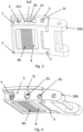
- FIG. 1 shows a first perspective view of a device 1 for adjusting the useful length of a bracelet according to an embodiment of the present invention.
- This device comprises a cover 6 to which a first end 20a of a bracelet is fixed.
- the cover 6 comprises two side walls 6a extending in the longitudinal axis of the bracelet.
- the Figure 2 has the same device as the Figure 1 but without the cover 6.
- a device 10 can then be distinguished for opening a folding clasp.
- a carriage 3 can also be distinguished comprising a locking member 4 which cooperates with the teeth 2a of the lateral racks 2 which are configured to be made integral with the lateral walls 6a of the cover 6 by means of pins 2c.
- the carriage 3 is designed to be made integral with the second end 20b of the bracelet, here in the form of the last link of the bracelet.
- the last link 20b is fixed to the carriage 3 by means of a cylindrical pin 3b in a manner similar to the fixing of the different links of a bracelet.
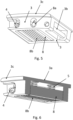
- FIG. 3 shows a perspective view of the carriage 3, the racks 2 and the link 20b and allows to understand the operation of the device of the present invention.
- the carriage 3 comprises a push button 8 to which is fixed the locking member 4 which allows to fix the position of the carriage 3 relative to the racks 2.
- the carriage 3 is in the most extreme position corresponding to the shortest length of the bracelet which is adjustable by the device 1.
- the locking member 4 is located at the bottom of a notch 2b formed by the teeth 2a of the racks 2. In order to be able to extend the length of the bracelet, it is easily understood that it is necessary to disengage the locking member from the teeth 2a.
- the press button 8 which is accessible to the user when the clasp is open.
- the press button comprises grooves 8a.
- the carriage comprises elastic members 5 (see Figure 6 ), here in the form of spiral springs, which are compressed between the push button 8 and the cover 3a of the carriage 3.
- the springs 5 push the locking member 4 to the bottom of the notches 2b of the racks 2 in order to fix the position of the carriage 3 and therefore of the link 20b.
- the push button also includes a guide pin 8a which cooperates with notches provided on each side of the carriage 3 in order to guide the movement of the push button when the member is disengaged. of locking teeth 2a.
- the carriage 3 comprises on each side a cantilever 3c configured to cooperate with the upper edges of the racks so that the carriage during movement slides on the racks which makes it possible to guide the movement of the carriage. Note that the presence of the cantilever 3c is optional.
- the width of the carriage 3 is chosen to be essentially equal to the lateral distance between the racks which guarantees that the movement of the carriage is only a movement along the longitudinal direction of the bracelet.
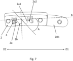
- the profile of the teeth 2a of the racks is, seen in profile, asymmetrical.
- the first flank 2a1 is oriented essentially perpendicular to the longitudinal axis B of the bracelet. This ensures that, even if the user exerts a traction force in the direction D1 on the carriage 3 or on the link 20b without disengaging the locking member by means of the press button 8, the length of the bracelet cannot be lengthened.
- the second flanks 2a2 of the teeth 2 are inclined towards the first end of the bracelet.
- the inclination of the second flanks 2a2 allows that when a determined thrust force is exerted by a user on the carriage 3 or on the link 20b in the direction D2, the force is transmitted to the locking member 4 so as to disengage the latter from the teeth 2a of the racks 2 and to cause a movement of the carriage 3 in the direction longitudinal resulting in the shortening of the useful length of the bracelet.
- the profile of the teeth 2a of the racks 2 therefore makes it possible to achieve a handcuff effect, that is to say that when the clasp is closed, it is possible for the user to shorten the length of the bracelet by exerting a pushing force along the direction D2 but it is not possible to lengthen the bracelet by exerting a pulling force in the direction D1. To lengthen the bracelet, it is necessary to open the bracelet to gain access to the push button 8 in order to disengage the locking member 4 from the teeth 2a.
- the thrust force required to enable the carriage 3 to move is determined by the shape and profile of the teeth 2a, the shape of the locking member 4 and by the spring constant of the springs 5.
- the locking member 4 is designed to be cylindrical and pivotable along its longitudinal axis. This allows the locking member to pivot during the shortening movement in the direction D2 and guarantees minimal wear of the teeth of the racks 2 over time.
Landscapes
- Buckles (AREA)
Priority Applications (1)
| Application Number | Priority Date | Filing Date | Title |
|---|---|---|---|
| EP23180205.9A EP4480340A1 (de) | 2023-06-20 | 2023-06-20 | Vorrichtung zur einstellung der nutzlänge eines armbandes und verschluss mit einer solchen vorrichtung |
Applications Claiming Priority (1)
| Application Number | Priority Date | Filing Date | Title |
|---|---|---|---|
| EP23180205.9A EP4480340A1 (de) | 2023-06-20 | 2023-06-20 | Vorrichtung zur einstellung der nutzlänge eines armbandes und verschluss mit einer solchen vorrichtung |
Publications (1)
| Publication Number | Publication Date |
|---|---|
| EP4480340A1 true EP4480340A1 (de) | 2024-12-25 |
Family
ID=86904063
Family Applications (1)
| Application Number | Title | Priority Date | Filing Date |
|---|---|---|---|
| EP23180205.9A Pending EP4480340A1 (de) | 2023-06-20 | 2023-06-20 | Vorrichtung zur einstellung der nutzlänge eines armbandes und verschluss mit einer solchen vorrichtung |
Country Status (1)
| Country | Link |
|---|---|
| EP (1) | EP4480340A1 (de) |
Citations (4)
| Publication number | Priority date | Publication date | Assignee | Title |
|---|---|---|---|---|
| FR692263A (fr) * | 1930-02-27 | 1930-11-04 | Louis Gottlieb & Sohne Ohg | Bracelet-montre |
| DE7313199U (de) * | 1973-04-07 | 1973-07-19 | Fischer A | Faltverschluß fur Uhrarmbander |
| JPH04329902A (ja) * | 1991-04-30 | 1992-11-18 | Casio Comput Co Ltd | 伸縮バックル構造 |
| EP2601856A1 (de) * | 2011-12-09 | 2013-06-12 | Omega SA | Verschluss eines Uhrenarmbands |
-
2023
- 2023-06-20 EP EP23180205.9A patent/EP4480340A1/de active Pending
Patent Citations (4)
| Publication number | Priority date | Publication date | Assignee | Title |
|---|---|---|---|---|
| FR692263A (fr) * | 1930-02-27 | 1930-11-04 | Louis Gottlieb & Sohne Ohg | Bracelet-montre |
| DE7313199U (de) * | 1973-04-07 | 1973-07-19 | Fischer A | Faltverschluß fur Uhrarmbander |
| JPH04329902A (ja) * | 1991-04-30 | 1992-11-18 | Casio Comput Co Ltd | 伸縮バックル構造 |
| EP2601856A1 (de) * | 2011-12-09 | 2013-06-12 | Omega SA | Verschluss eines Uhrenarmbands |
Similar Documents
| Publication | Publication Date | Title |
|---|---|---|
| EP2606762B1 (de) | Armbandverschluss mit verschiedenen Längenregulierungen | |
| EP3769640B1 (de) | Verschluss für uhrenarmband | |
| EP2875747B1 (de) | Armbandverschluss, der eine Feinreguliervorrichtung der Nutzlänge des Armbands umfasst | |
| EP3210488B1 (de) | Armbandverschluss, der eine reguliervorrichtung der länge des armbands umfasst | |
| EP2361523B1 (de) | Verschluss für Armband | |
| EP3412168B1 (de) | Verschluss für armband | |
| EP1588640B1 (de) | Längeneinstellungsvorrichtung eines Bandes, insbesondere für ein Uhrarmband | |
| EP0350785A1 (de) | Dehnbarer Armbandverschluss mit Feineinstellung | |
| EP3266335A1 (de) | Armbanduhr | |
| EP1943917B1 (de) | Klappbarer Verschluss für Armband | |
| WO1998034163A1 (fr) | Dispositif pour la fixation d'un bracelet a une boite de montre | |
| EP3501325B1 (de) | Verschluss für armband | |
| CH698981B1 (fr) | Dispositif de réglage de longueur pour bracelet, fermoire de bracelet et bracelet munis d'un tel dispositif. | |
| EP4480340A1 (de) | Vorrichtung zur einstellung der nutzlänge eines armbandes und verschluss mit einer solchen vorrichtung | |
| EP0115364B1 (de) | Faltverschluss für Armbänder | |
| CH705058B1 (fr) | Fermoir. | |
| CH695656A5 (fr) | Maillon réglable en longueur notamment pour bracelet à maillons. | |
| CH663522A5 (en) | Bracelet clasp | |
| EP3292784B1 (de) | Verschluss einer armbanduhr | |
| CH704197A2 (fr) | Fermoir pour lien souple ou articulé tel que bracelet, bracelet de montre, ceinture. | |
| EP4151116A1 (de) | Befestigungssystem für austauschbares band | |
| EP1716776A2 (de) | Vorrichtung zur Korrektur der Länge eines Armbandes mit Faltverschluss | |
| EP1304054B1 (de) | Verschluss | |
| CH710481A2 (fr) | Bracelet pour montres classiques ou connectées. | |
| EP0287475B1 (de) | Verstellbare Befestigungseinrichtung für ein Armbandende, insbesondere für ein Uhrenarmband |
Legal Events
| Date | Code | Title | Description |
|---|---|---|---|
| PUAI | Public reference made under article 153(3) epc to a published international application that has entered the european phase |
Free format text: ORIGINAL CODE: 0009012 |
|
| STAA | Information on the status of an ep patent application or granted ep patent |
Free format text: STATUS: THE APPLICATION HAS BEEN PUBLISHED |
|
| AK | Designated contracting states |
Kind code of ref document: A1 Designated state(s): AL AT BE BG CH CY CZ DE DK EE ES FI FR GB GR HR HU IE IS IT LI LT LU LV MC ME MK MT NL NO PL PT RO RS SE SI SK SM TR |
|
| STAA | Information on the status of an ep patent application or granted ep patent |
Free format text: STATUS: REQUEST FOR EXAMINATION WAS MADE |
|
| 17P | Request for examination filed |
Effective date: 20250620 |