EP4474742A2 - Trocknungsvorrichtung und ofen - Google Patents
Trocknungsvorrichtung und ofen Download PDFInfo
- Publication number
- EP4474742A2 EP4474742A2 EP24209300.3A EP24209300A EP4474742A2 EP 4474742 A2 EP4474742 A2 EP 4474742A2 EP 24209300 A EP24209300 A EP 24209300A EP 4474742 A2 EP4474742 A2 EP 4474742A2
- Authority
- EP
- European Patent Office
- Prior art keywords
- air
- outlet channel
- sub
- drying
- connecting portion
- Prior art date
- Legal status (The legal status is an assumption and is not a legal conclusion. Google has not performed a legal analysis and makes no representation as to the accuracy of the status listed.)
- Granted
Links
Images


Classifications
-
- F26B21/37—
-
- F26B21/50—
Definitions
- the present application relates to the field of drying technologies, and in particular, to a drying apparatus and an oven.
- An existing drying apparatus blows a material dry by delivering gas to the material.
- An air outlet on the drying apparatus has a fixed area, and therefore, an air speed or an air volume cannot be adjusted adaptively, resulting in a low drying efficiency.
- CN212157928U relates to a drying machine comprising an air flowing cavity, a lower-layer air outlet cavity, an upper-layer air outlet cavity, an air brake installation cavity and an air passing cavity, the air flowing cavity is communicated with the air brake installation cavity, the air brake installation cavity is communicated with the lower-layer air outlet cavity and the air passing cavity, and the air passing cavity is communicated with the upper-layer air outlet cavity.
- the upper-layer air outlet chamber and the lower-layer air outlet chamber are respectively communicated with the air outlet chamber through an air outlet channel, and a cloth outlet channel is arranged between the upper-layer air outlet chamber and the lower-layer air outlet chamber;
- the upper-layer air outlet chamber is provided with a plurality of groups of upper nozzles;
- the lower-layer air outlet chamber is provided with a plurality of groups of lower nozzles;
- an air brake is arranged in the air brake installation cavity and comprises an air baffle, an air baffle rotating shaft and a sealing connection plate, the rotating shaft is arranged in the center of the air baffle, the air baffle can rotate around the rotating shaft, and when the air baffle makes contact with the sealing connection plate, the air brake installation cavity is not communicated with the lower-layer air outlet cavity.
- CN208108724U relates to a drying equipment, concretely relates to a substrate drying device, solved present drying device and can't satisfy the different requirement of needs hot blast rate whendrying of different substrates, it includes drying -machine body, material conveying mechanism and heating element, this internal hot air bellow that is equipped with of drying -machine, hot air bellow intercommunication has the fan, heating element includes: set up outside the drying -machine body and the cistern that connects gradually, heat pump set, steam heat exchanger and set up the coil pipe in a hot air bellow, the coil pipe is connected with the cistern, a hot air bellow has offered a plurality of air outlets along its length direction in the bottom.
- CN210242218U relates to a partition plate dividing an inner cavity of a box body into an air blowing chamber on the upper side and a drying chamber on the lower side is arranged in the box body, an air blowing opening extending front and back is formed in the left side of the partition plate, an air return opening extending front and back is formed in the right side of the partition plate, and an air blowing heating mechanism is arranged in the air blowing chamber.
- a left air guide wall for dividing the drying chamber into a left air guide chamber and a right chamber is arranged in the drying chamber;
- the left air guide wall comprises a plurality of air guide plates which are vertically arranged at intervals and adjustable in inclination angle, the air guide plates extend in the length direction of the box body,the air guide plates are obliquely arranged with the right side edge low and the left side edge high, and the inclination angle between the lower side air guide plate and the horizontal plane is larger than that between the adjacent upper side air guide plate and the horizontal plane.
- the present application provides a drying apparatus as set out in claim 1 and an oven as set out in claim 5, which is capable of realizing adjustment of an air speed without changing an air volume, thereby ensuring the drying efficiency.
- Other aspects of the invention can be found in the dependent claims.
- a drying apparatus for drying a material.
- the drying apparatus includes: a blowing mechanism having an air-outlet channel for conveying dry gas to the material; a guide member movably arranged in the air-outlet channel and used for dividing the air-outlet channel into a first sub-air-outlet channel and a second sub-air-outlet channel, and a first air outlet of the first sub-air-outlet channel and a second air outlet of the second sub-air-outlet channel both facing the material.
- the guide member By movably arranging the guide member in the air-outlet channel of the blowing mechanism, the guide member can divide the air-outlet channel into the first sub-air-outlet channel and the second sub-air-outlet channel when moving.
- the guide member does not change the area of a section of the air-outlet channel, and is only used for dividing the air-outlet channel into two sub-channels, therefore, a total air output of the drying apparatus does not change.
- Opening areas and internal volumes of the first sub-air-outlet channel and the second sub-air-outlet channel may be changed correspondingly with the movement of the guide member, and therefore, air speeds in the first sub-air-outlet channel and the second sub-air-outlet channel may be changed, thereby realizing adjustment of the air speed without changing the air volume.
- the first airoutlet of the first sub-air-outlet channel and the second air outlet of the second sub-air-outlet channel are both arranged to face the material, so that air flows from the air-outlet channel to the first sub-air-outlet channel and the second sub-air-outlet channel will eventually blow to the material, thereby fully ensuring the drying efficiency of the drying apparatus for the material.
- a rotation shaft is rotationally arranged in the air-outlet channel, and the guide member is fixed on the rotation shaft.
- the guide member changes air outputs of the first air outlet and the second air outlet.
- the blowing mechanism includes a first rotational connecting portion and a second rotational connecting portion arranged oppositely.
- the guide member is located between the first rotational connecting portion and the second rotational connecting portion, and the rotation shaft is rotationally connected to the first rotational connecting portion and the second rotational connecting portion.
- the first arc-shaped protrusion and the second arc-shaped protrusion are arranged on the first rotational connecting portion and the second rotational connecting portion respectively, and the rotation shaft is arranged on the first arc-shaped protrusion and the second arc-shaped protrusion respectively, so that the rotation shaft and the guide member can be conveniently placed on the blowing mechanism or taken off from the blowing mechanism under the support of the first arc-shaped protrusion and the second arc-shaped protrusion, and the rotation shaft and the guide member can rotate smoothly for adjustment.
- the first rotational connecting portion is provided with a first connecting hole
- the second rotational connecting portion is provided with a second connecting hole
- the first connecting hole and the second connecting hole are arranged oppositely
- the rotation shaft is rotationally arranged in the first connecting hole and the second connecting hole respectively.
- the first connecting hole and the second connecting hole are arranged on the first rotational connecting portion and the second rotational connecting portion respectively, and the rotation shaft is rotationally arranged in the first connecting hole and the second connecting hole respectively, so that the rotation shaft and the guide member are reliably connected to the blowing mechanism, thereby ensuring the stability of an overall structure of the drying apparatus.
- an outer cover of the second sub-air-outlet channel is provided with an air box, one side of the air box facing the material is provided with an opening, and the air box is used for accommodating the gas blown from the second sub-air-outlet channel, so that the gas is blown to the material from the opening.
- the air box is arranged on the outer cover of the second sub-air-outlet channel to accommodate the gas blown out of the second sub-air-outlet channel in the air box, and by arranging the opening on the side of the air box facing the material, the gas accommodated in the air box can be smoothly blown to the material through the opening, thereby ensuring the drying efficiency of the drying apparatus for the material.
- the opening is provided with a guide plate
- the guide plate is provided with meshes.
- the mesh can provide uniform dispersion and guidance for the gas in the air box. Specifically, the mesh evenly distributes the gas in the air box to different holes and guides the gas to blow to the material, so that the air flow on the material surface is more uniform, which is conducive to ensuring the uniformity of the drying degree of the material surface.
- an oven which includes the drying apparatus in any of the above methods.
- the guide member can divide the air-outlet channel into the first sub-air-outlet channel and the second sub-air-outlet channel when moving.
- the guide member does not change the area of a section of the air-outlet channel, and is only used for dividing the air-outlet channel into two sub-channels; therefore, a total air output of the drying apparatus does not change.
- Opening areas and internal volumes of the first sub-air-outlet channel and the second sub-air-outlet channel may be changed correspondingly with the movement of the guide member, and therefore, air speeds in the first sub-air-outlet channel and the second sub-air-outlet channel may be changed, thereby realizing adjustment of the air speed without changing the air volume.
- the first air outlet of the first sub-air-outlet channel and the second air outlet of the second sub-air-outlet channel are both arranged to face the material, so that air flows from the air-outlet channel to the first sub-air-outlet channel and the second sub-air-outlet channel will eventually blow to the material, thereby fully ensuring the drying efficiency of the oven for the material.
- air boxes are arranged on both sides of the plurality of drying apparatuses in the preset direction, and the air boxes between adjacent drying apparatuses are in communication with each other.
- drying apparatus 100 blowing mechanism 110, air-outlet channel 111, first sub-air-outlet channel 1111, first air outlet 1111a, second sub-air-outlet channel 1112, second air outlet 1112a, first rotational connecting portion 112, first arc-shaped protrusion 1121, first connecting hole 1122, second rotational connecting portion 113, second arc-shaped protrusion 1131, second connecting hole 1132, guide member 120, rotation shaft 130, air box 140, opening 141, guide plate 150, meshes 151, adjusting member 160, oven 10; material 200.
- an embodiment means that a particular feature, structure, or characteristic described in connection with the embodiment can be included in at least one embodiment of the present application.
- the appearance of this phrase in various places in the specification does not necessarily refer to the same embodiment, nor is it a separate or alternative embodiment that is mutually exclusive with other embodiments. It is explicitly and implicitly understood by those skilled in the art that the embodiments described herein may be combined with other embodiments.
- a plurality of refers to two or more (including two), and similarly, “multiple groups” refers to two or more (including two) groups, and “multiple sheets” refers to two or more (including two) sheets.
- the technical terms “mount”, “join”, “connect”, “fix”, etc. should be understood in a broad sense, such as, a fixed connection, a detachable connection, or an integral connection; a mechanical connection, or an electrical connection; a direct connection, an indirect connection through an intermediate medium, an internal connection of two elements, or interaction between two elements.
- the specific meanings of the above terms in the embodiments of the present application can be understood according to specific situations.
- drying apparatuses that perform drying by blowing air
- areas of air outlets on some drying apparatuses are fixed, and the air speed or air volume cannot be adjusted adaptively, so the drying efficiency is low.
- Some drying apparatuses have wind shields in air flow channels. By moving the wind shield, the area of an air flow channel will be increased or decreased, thereby realizing the adjustment of the air speed and air volume.
- the air volume will increase with the increase of the air speed and decrease with the decrease of the air speed, it is difficult to be adjusted to an appropriate position, thereby affecting the drying efficiency.
- a drying apparatus is proposed in the present application.
- the guide member By movably arranging a guide member in an air-outlet channel of a blowing mechanism, the guide member can divide the air-outlet channel into a first sub-air-outlet channel and a second sub-air-outlet channel when moving.
- the guide member does not change the area of a section of the air-outlet channel, and is only used for dividing the air-outlet channel into two sub-channels; therefore, a total air output of the drying apparatus does not change.
- Air speeds of the first sub-air-outlet channel and the second sub-air-outlet channel may be changed correspondingly with the movement of the guide member, thereby realizing adjustment of the air speed without changing the air volume, and ensuring the drying efficiency of the drying apparatus for the material.
- a drying apparatus for drying a material is provided.
- Fig. 1 shows a three-dimensional structure of drying apparatus 100 according to an embodiment of the present application
- Fig. 2 shows a three-dimensional structure of blowing mechanism 110 and guide member 120 in drying apparatus 100 according to an embodiment
- Fig. 3 shows a sectional structure of drying apparatus 100 according to an embodiment.
- Drying apparatus 100 includes blowing mechanism 110 and guide member 120.
- the blowing mechanism 110 is provided with air-outlet channel 111, and air-outlet channel 111 is used for delivering dry gas to material 200.
- Guide member 120 is movably arranged in air-outlet channel 111, and is used for dividing air-outlet channel 111 into first sub-air-outlet channel 1111 and second sub-air-outlet channel 1112.
- First air outlet 1111a of first sub-air-outlet channel 1111 and second air outlet 1112a of second sub-air-outlet channel 1112 both face material 200.
- the specific structure in Fig. 1 and Fig. 2 is a structure shown by drying apparatus 100 after a part is cut off.
- both sides of blowing mechanism 110 in drying apparatus 100 in Fig. 1 and Fig. 2 with openings in a length direction of guide member 120 are provided with complete side walls to ensure the closure of an internal gas flow channel of blowing mechanism 110.
- Material 200 may be an electrode sheet substrate coated with a conductive material as shown in Fig. 1 .
- drying apparatus 100 blows air to a substrate material, so that the conductive material is dried and adhered to the electrode sheet substrate to form an electrode sheet.
- the electrode sheet substrate may be, for example, a current collector. It is understandable that material 200 may also be a coated textile, a plastic structure, or the like.
- Blowing mechanism 110 may be an air knife as shown in the figure.
- the air knife may be driven by a vortex blower or a high-pressure centrifugal blower. After gas is compressed, it may be blown out at a high speed in the form of a thin airflow sheet with a smaller thickness to achieve the drying of material 200.
- Guide member 120 may be a plate structure. Guide member 120 may be rotationally arranged in air-outlet channel 111 as shown in Fig. 3 , and a rotating direction is a direction shown by an arrow in Fig. 3 , so that air-outlet channel 111 may be divided into first sub-air-outlet channel 1111 and second sub-air-outlet channel 1112 by rotating guide member 120.
- FIG. 4 the figure shows a sectional structure of drying apparatus 100 according to an embodiment of the present application.
- guide member 120 may also be slidably arranged in air-outlet channel 111, and a sliding direction is a direction shown by an arrow in Fig. 4 , so that air-outlet channel 111 may be divided into first sub-air-outlet channel 1111 and second sub-air-outlet channel 1112 by sliding guide member 120.
- guide member 120 may divide air-outlet channel 111 into first sub-air-outlet channel 1111 and second sub-air-outlet channel 1112 when moving.
- Guide member 120 does not change the area of a section of air-outlet channel 111, and is only used for dividing air-outlet channel 111 into two sub-channels; therefore, a total air output of drying apparatus 100 does not change.
- Opening areas and internal volumes of first sub-air-outlet channel 1111 and second sub-air-outlet channel 1112 may be changed correspondingly with the movement of guide member 120, and therefore, air speeds in first sub-air-outlet channel 1111 and second sub-air-outlet channel 1112 may be changed, thereby realizing adjustment of the air speed without changing the air volume.
- first air outlet 1111a of first sub-air-outlet channel 1111 and second air outlet 1112a of second sub-air-outlet channel 1112 are both arranged to face material 200, so that air flows from air-outlet channel 111 to first sub-air-outlet channel 1111 and second sub-air-outlet channel 1112 will eventually be blown to material 200, thereby fully ensuring the drying efficiency of drying apparatus 100 for material 200.
- rotation shaft 130 is rotationally arranged in air-outlet channel 111
- guide member 120 is fixed on rotation shaft 130, and when rotating with rotation shaft 130, guide member 120 changes air outputs of first air outlet 1111a and second air outlet 1112a.
- guide member 120 may be fixed on an annular side of rotation shaft 130 by welding, and rotation shaft 130 may be arranged on an outer side of guide member 120 as shown in the figure.
- rotation shaft 130 and blowing mechanism 110 may not be connected, and rotation shaft 130 may be connected to an external supporting structure (such as a supporting hole) after at least one end extending and projecting out of a surface of blowing mechanism 110, thereby realizing fixing of rotation shaft 130 and guide member 120 at a required position.
- rotation shaft 130 may also be arranged on an inner side of guide member 120, and both ends of rotation shaft 130 are rotationally connected to the side walls of blowing mechanism 110 (that is, side walls not drawn at both ends of blowing mechanism 110 in a length direction of guide member 120 or an axis direction of rotation shaft 130 in Fig. 1 and Fig. 2 ).
- a connecting hole may also be arranged on guide member 120, and rotation shaft 130 is penetrated into the connecting hole and fixedly connected to guide member 120.
- rotation shaft 130 By rotationally arranging rotation shaft 130 in air-outlet channel 111 and fixing guide member 120 on rotation shaft 130, convenient control of guide member 120 may be achieved by rotating rotation shaft 130 to adjust opening sizes of first sub-air-outlet channel 1111 and second sub-air-outlet channel 1112, so that the air outputs of first air outlet 1111a and second air outlet 1112a may change inversely without changing the total air output, and corresponding adjustment may be performed according to actual requirements to achieve the best drying efficiency.
- blowing mechanism 110 includes first rotational connecting portion 112 and second rotational connecting portion 113, guide member 120 is located between first rotational connecting portion 112 and second rotational connecting portion 113, and rotation shaft 130 is rotationally connected to first rotational connecting portion 112 and second rotational connecting portion 113.
- first rotational connecting portion 112 and second rotational connecting portion 113 are parts on the shell of blowing mechanism 110 located at both ends of guide member 120.
- First rotational connecting portion 112 and second rotational connecting portion 113 may be provided with structures such as a bearing and a connecting hole, for being rotationally connected to rotation shaft 130.
- guide member 120 By arranging guide member 120 between first rotational connecting portion 112 and second rotational connecting portion 113, and rotationally connecting rotation shaft 130 to first rotational connecting portion 112 and second rotational connecting portion 113, guide member 120 can be smoothly fixed on blowing mechanism 110 when it rotates to the desired position.
- First arc-shaped protrusion 1121 and second arc-shaped protrusion 1131 are arranged on first rotational connecting portion 112 and second rotational connecting portion 113 respectively, and rotation shaft 130 is arranged on first arc-shaped protrusion 1121 and second arc-shaped protrusion 1131 respectively, so that rotation shaft 130 and guide member 120 can be conveniently placed on blowing mechanism 110 or taken off from blowing mechanism 110 under the support of first arc-shaped protrusion 1121 and second arc-shaped protrusion 1131, and rotation shaft 130 and guide member 120 can rotate smoothly for adjustment.
- first rotational connecting portion 112 is provided with first connecting hole 1122
- second rotational connecting portion 113 is provided with second connecting hole 1132
- first connecting hole 1122 and second connecting hole 1132 are arranged oppositely
- rotation shaft 130 is rotationally arranged in first connecting hole 1122 and second connecting hole 1132 respectively.
- First connecting hole 1122 and second connecting hole 1132 may be both blind holes, or both through holes, or one blind hole and one through hole.
- an outer cover of second sub-air-outlet channel 1112 is provided with air box 140, one side of air box 140 facing material 200 is provided with an opening 141, and air box 140 is used for accommodating the gas blown from second sub-air-outlet channel 1112, so that the gas is blown to material 200 from opening 141.
- opening 141 may be formed by hollowing out one side of air box 140 facing material 200 as shown in Fig. 3 , or by opening a through hole on a side wall of air box 140 facing material 200.
- the gas blown from second sub-air-outlet channel 1112 is accommodated in air box 140, and by arranging opening 141 on the side of air box 140 facing material 200, the gas accommodated in air box 140 may be smoothly blown to material 200 through opening 141, thereby ensuring the drying efficiency of drying apparatus 100 for material 200.
- meshes 151 may be circular, elliptical, square, rhombic, polygonal, or the like, which is not limited here.
- mesh 151 can provide uniform dispersion and guidance for the gas in air box 140. Specifically, mesh 151 evenly disperses the gas in air box 140 into different holes and guides the gas to blow to material 200, so that the air flow on the surface of material 200 is more uniform, which is conducive to ensuring the uniformity of the drying degree of the surface of material 200.
- an oven is provided.
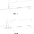
- Fig. 7 it shows a structure of oven 10 according to an embodiment of the present application.
- oven 10 includes drying apparatus 100.
- drying apparatus 100 There are a plurality of drying apparatuses 100, and the plurality of drying apparatuses 100 are arranged in a preset direction.
- the preset direction is a direction shown by an arrow in the figure, and when material 200 is an electrode sheet substrate coated with a conductive material, the preset direction may be a delivering direction of feeding and drying the electrode sheet substrate. It should be noted that in other embodiments, the preset direction may be any direction, and a corresponding design may be made specifically according to a product shape or structural characteristics of the material to be dried, which will not be repeated here.
- the plurality of drying apparatuses 100 may be connected to the same air supply pipeline to reduce space occupation, and optimize the layout of the production line. Moreover, each drying apparatus 100 in oven 10 may be individually adjusted through guide member 120 to achieve the optimal drying effect.
- guide member 120 may divide air-outlet channel 111 into first sub-air-outlet channel 1111 and second sub-air-outlet channel 1112 when moving.
- Guide member 120 does not change the area of a section of air-outlet channel 111, and is only used for dividing air-outlet channel 111 into two sub-channels; therefore, a total air output of drying apparatus 100 does not change.
- Opening areas and internal volumes of first sub-air-outlet channel 1111 and second sub-air-outlet channel 1112 may be changed correspondingly with the movement of guide member 120, and therefore, air speeds in first sub-air-outlet channel 1111 and second sub-air-outlet channel 1112 may be changed, thereby realizing adjustment of the air speed without changing the air volume.
- first air outlet 1111a of first sub-air-outlet channel 1111 and second air outlet 1112a of second sub-air-outlet channel 1112 are both arranged to face material 200, so that air flows from air-outlet channel 111 to first sub-air-outlet channel 1111 and second sub-air-outlet channel 1112 will eventually be blown to material 200, thereby fully ensuring the drying efficiency of oven 10 for material 200.
- FIG. 10 shows a structure of an oven according to another embodiment.
- air boxes 140 are arranged on both sides of a plurality of drying apparatuses 100 in a preset direction, and air boxes 140 between adjacent drying apparatuses 100 communicate with each other.
- Clause 2 The drying apparatus (100) according to clause 1, wherein a rotation shaft (130) is rotationally arranged in the air-outlet channel (111), the guide member (120) is fixed on the rotation shaft (130), and when rotating with the rotation shaft (130), the guide member (120) changes air outputs of the first air outlet (11 11a) and the second air outlet (1112a).
- Clause 3 The drying apparatus (100) according to clause 2, wherein the blowing mechanism (110) comprises a first rotational connecting portion (112) and a second rotational connecting portion (113) arranged oppositely, the guide member (120) is located between the first rotational connecting portion (112) and the second rotational connecting portion (113), and the rotation shaft (130) is rotationally connected to the first rotational connecting portion (112) and the second rotational connecting portion (113).
- the blowing mechanism (110) comprises a first rotational connecting portion (112) and a second rotational connecting portion (113) arranged oppositely
- the guide member (120) is located between the first rotational connecting portion (112) and the second rotational connecting portion (113)
- the rotation shaft (130) is rotationally connected to the first rotational connecting portion (112) and the second rotational connecting portion (113).
- Clause 4 The drying apparatus (100) according to clause 3, wherein a surface of the first rotational connecting portion (112) protrudes to form a first arc-shaped protrusion (1121), a surface of the second rotational connecting portion (113) protrudes to form a second arc-shaped protrusion (1131), the first arc-shaped protrusion (1121) and the second arc-shaped protrusion (1131) are arranged oppositely, and the rotation shaft (130) is rotationally arranged on the first arc-shaped protrusion (1121) and the second arc-shaped protrusion (1131) respectively.
- Clause 5 The drying apparatus (100) according to clause 3, wherein the first rotational connecting portion (112) is provided with a first connecting hole (1122), the second rotational connecting portion (113) is provided with a second connecting hole (1132), the first connecting hole (1122) and the second connecting hole (1132) are arranged oppositely, and the rotation shaft (130) is rotationally arranged in the first connecting hole (1122) and the second connecting hole (1132) respectively.
- Clause 6 The drying apparatus (100) according to any of clauses 1 to 5, wherein an outer cover of the second sub-air-outlet channel (1112) is provided with an air box (140), one side of the air box (140) facing the material (200) is provided with an opening (141), and the air box (140) is used for accommodating the gas blown from the second sub-air-outlet channel (1112), so that the gas is blown to the material (200) from the opening (141).
- Clause 7 The drying apparatus (100) according to clause 6, wherein the opening (141) is provided with a guide plate (150), and the guide plate (150) is provided with meshes (151).
- Clause 8 The drying apparatus (100) according to any one of clauses 2 to 7, wherein one end of the rotation shaft (130) is provided with an adjusting member (160).
- Clause 10 The oven (10) according to clause 9, wherein air boxes (140) are arranged on both sides of the plurality of drying apparatuses (100) in the preset direction, and the air boxes (140) between adjacent drying apparatuses (100) are in communication with each other.
Landscapes
- Drying Of Solid Materials (AREA)
- Engineering & Computer Science (AREA)
- Mechanical Engineering (AREA)
- General Engineering & Computer Science (AREA)
Applications Claiming Priority (2)
| Application Number | Priority Date | Filing Date | Title |
|---|---|---|---|
| CN202220401766.0U CN217154922U (zh) | 2022-02-25 | 2022-02-25 | 一种干燥装置及烘箱 |
| EP23158512.6A EP4235071B1 (de) | 2022-02-25 | 2023-02-24 | Trocknungsvorrichtung und ofen |
Related Parent Applications (2)
| Application Number | Title | Priority Date | Filing Date |
|---|---|---|---|
| EP23158512.6A Division EP4235071B1 (de) | 2022-02-25 | 2023-02-24 | Trocknungsvorrichtung und ofen |
| EP23158512.6A Division-Into EP4235071B1 (de) | 2022-02-25 | 2023-02-24 | Trocknungsvorrichtung und ofen |
Publications (3)
| Publication Number | Publication Date |
|---|---|
| EP4474742A2 true EP4474742A2 (de) | 2024-12-11 |
| EP4474742A3 EP4474742A3 (de) | 2025-03-12 |
| EP4474742B1 EP4474742B1 (de) | 2025-11-05 |
Family
ID=82691188
Family Applications (2)
| Application Number | Title | Priority Date | Filing Date |
|---|---|---|---|
| EP23158512.6A Active EP4235071B1 (de) | 2022-02-25 | 2023-02-24 | Trocknungsvorrichtung und ofen |
| EP24209300.3A Active EP4474742B1 (de) | 2022-02-25 | 2023-02-24 | Trocknungsvorrichtung und ofen |
Family Applications Before (1)
| Application Number | Title | Priority Date | Filing Date |
|---|---|---|---|
| EP23158512.6A Active EP4235071B1 (de) | 2022-02-25 | 2023-02-24 | Trocknungsvorrichtung und ofen |
Country Status (5)
| Country | Link |
|---|---|
| US (1) | US20230272975A1 (de) |
| EP (2) | EP4235071B1 (de) |
| CN (1) | CN217154922U (de) |
| ES (1) | ES3013068T3 (de) |
| HU (1) | HUE069910T2 (de) |
Families Citing this family (3)
| Publication number | Priority date | Publication date | Assignee | Title |
|---|---|---|---|---|
| CN221549254U (zh) * | 2023-09-28 | 2024-08-16 | 宁德时代新能源科技股份有限公司 | 通风装置 |
| CN117387315B (zh) * | 2023-10-18 | 2025-10-03 | 河北金力新能源科技股份有限公司 | 一种便于回收烘箱泄漏气体的吸气机构 |
| CN120627614B (zh) * | 2025-08-11 | 2025-11-14 | 中胶(内蒙古)新材料有限责任公司 | 一种风量智能调节装置及烘箱 |
Citations (3)
| Publication number | Priority date | Publication date | Assignee | Title |
|---|---|---|---|---|
| CN208108724U (zh) | 2018-02-11 | 2018-11-16 | 广州市创坤金葱粉皮革有限公司 | 一种底材烘干装置 |
| CN210242218U (zh) | 2019-08-12 | 2020-04-03 | 临朐县钰坤机械设备厂 | 一种分风板角度可调式的烘干箱 |
| CN212157928U (zh) | 2020-10-26 | 2020-12-15 | 广东三技克朗茨机械科技有限公司 | 一种烘干机 |
Family Cites Families (2)
| Publication number | Priority date | Publication date | Assignee | Title |
|---|---|---|---|---|
| KR101229347B1 (ko) * | 2012-09-05 | 2013-02-05 | 일성기계공업 주식회사 | 텐터기의 열풍분사노즐 및 이를 이용한 텐터기의 열풍분사장치 |
| CN111219956B (zh) * | 2018-11-27 | 2023-05-23 | 青岛海高设计制造有限公司 | 风干机及其控制方法 |
-
2022
- 2022-02-25 CN CN202220401766.0U patent/CN217154922U/zh active Active
-
2023
- 2023-02-23 US US18/173,747 patent/US20230272975A1/en active Pending
- 2023-02-24 EP EP23158512.6A patent/EP4235071B1/de active Active
- 2023-02-24 HU HUE23158512A patent/HUE069910T2/hu unknown
- 2023-02-24 ES ES23158512T patent/ES3013068T3/es active Active
- 2023-02-24 EP EP24209300.3A patent/EP4474742B1/de active Active
Patent Citations (3)
| Publication number | Priority date | Publication date | Assignee | Title |
|---|---|---|---|---|
| CN208108724U (zh) | 2018-02-11 | 2018-11-16 | 广州市创坤金葱粉皮革有限公司 | 一种底材烘干装置 |
| CN210242218U (zh) | 2019-08-12 | 2020-04-03 | 临朐县钰坤机械设备厂 | 一种分风板角度可调式的烘干箱 |
| CN212157928U (zh) | 2020-10-26 | 2020-12-15 | 广东三技克朗茨机械科技有限公司 | 一种烘干机 |
Also Published As
| Publication number | Publication date |
|---|---|
| EP4474742B1 (de) | 2025-11-05 |
| EP4235071C0 (de) | 2024-12-04 |
| EP4474742A3 (de) | 2025-03-12 |
| US20230272975A1 (en) | 2023-08-31 |
| EP4235071A1 (de) | 2023-08-30 |
| ES3013068T3 (en) | 2025-04-10 |
| HUE069910T2 (hu) | 2025-04-28 |
| CN217154922U (zh) | 2022-08-09 |
| EP4235071B1 (de) | 2024-12-04 |
Similar Documents
| Publication | Publication Date | Title |
|---|---|---|
| EP4474742A2 (de) | Trocknungsvorrichtung und ofen | |
| WO2021051895A1 (zh) | 室内机、空调器及空调器控制的方法 | |
| CN107166514A (zh) | 空调室内机 | |
| CN108981125B (zh) | 百叶机构及具有其的出风装置 | |
| CN217031376U (zh) | 空调器的室内机及空调器 | |
| CN217031378U (zh) | 空调器的室内机及空调器 | |
| CN211575272U (zh) | 空调室内机及具有其的空调器 | |
| CN110469911A (zh) | 室内机及具有其的空调器 | |
| CN109442573B (zh) | 一种空调出风装置以及空调器 | |
| CN210861594U (zh) | 风道组件及具有其的空调器 | |
| CN107842918A (zh) | 天花机 | |
| CN114135939A (zh) | 天花机 | |
| CN114087754A (zh) | 风道部件、室内机及空调器 | |
| JPH09210440A (ja) | 誘引式可変定風量装置 | |
| CN111380198A (zh) | 一种导风机构以及空调器 | |
| CN111306625A (zh) | 空调器 | |
| CN208418972U (zh) | 一种多面出风卡式空调机 | |
| CN217031380U (zh) | 用于空调器的送风筒及空调器 | |
| CN217274489U (zh) | 用于空调器的送风筒组件及空调器 | |
| CN210118834U (zh) | 空调室内机以及具有其的空调器 | |
| CN114838408A (zh) | 送风机构及具有其的空调器 | |
| CN212227361U (zh) | 空调器 | |
| CN211146687U (zh) | 室内机及具有其的空调器 | |
| CN209165590U (zh) | 一种空调出风装置以及空调器 | |
| CN210861393U (zh) | 空调器 |
Legal Events
| Date | Code | Title | Description |
|---|---|---|---|
| PUAI | Public reference made under article 153(3) epc to a published international application that has entered the european phase |
Free format text: ORIGINAL CODE: 0009012 |
|
| STAA | Information on the status of an ep patent application or granted ep patent |
Free format text: STATUS: THE APPLICATION HAS BEEN PUBLISHED |
|
| AC | Divisional application: reference to earlier application |
Ref document number: 4235071 Country of ref document: EP Kind code of ref document: P |
|
| AK | Designated contracting states |
Kind code of ref document: A2 Designated state(s): AL AT BE BG CH CY CZ DE DK EE ES FI FR GB GR HR HU IE IS IT LI LT LU LV MC ME MK MT NL NO PL PT RO RS SE SI SK SM TR |
|
| PUAL | Search report despatched |
Free format text: ORIGINAL CODE: 0009013 |
|
| AK | Designated contracting states |
Kind code of ref document: A3 Designated state(s): AL AT BE BG CH CY CZ DE DK EE ES FI FR GB GR HR HU IE IS IT LI LT LU LV MC ME MK MT NL NO PL PT RO RS SE SI SK SM TR |
|
| RIC1 | Information provided on ipc code assigned before grant |
Ipc: F26B 21/12 20060101AFI20250204BHEP |
|
| STAA | Information on the status of an ep patent application or granted ep patent |
Free format text: STATUS: REQUEST FOR EXAMINATION WAS MADE |
|
| 17P | Request for examination filed |
Effective date: 20250327 |
|
| GRAP | Despatch of communication of intention to grant a patent |
Free format text: ORIGINAL CODE: EPIDOSNIGR1 |
|
| STAA | Information on the status of an ep patent application or granted ep patent |
Free format text: STATUS: GRANT OF PATENT IS INTENDED |
|
| INTG | Intention to grant announced |
Effective date: 20250811 |
|
| GRAS | Grant fee paid |
Free format text: ORIGINAL CODE: EPIDOSNIGR3 |
|
| GRAA | (expected) grant |
Free format text: ORIGINAL CODE: 0009210 |
|
| STAA | Information on the status of an ep patent application or granted ep patent |
Free format text: STATUS: THE PATENT HAS BEEN GRANTED |
|
| AC | Divisional application: reference to earlier application |
Ref document number: 4235071 Country of ref document: EP Kind code of ref document: P |
|
| AK | Designated contracting states |
Kind code of ref document: B1 Designated state(s): AL AT BE BG CH CY CZ DE DK EE ES FI FR GB GR HR HU IE IS IT LI LT LU LV MC ME MK MT NL NO PL PT RO RS SE SI SK SM TR |
|
| REG | Reference to a national code |
Ref country code: CH Ref legal event code: F10 Free format text: ST27 STATUS EVENT CODE: U-0-0-F10-F00 (AS PROVIDED BY THE NATIONAL OFFICE) Effective date: 20251105 Ref country code: GB Ref legal event code: FG4D |
|
| REG | Reference to a national code |
Ref country code: DE Ref legal event code: R096 Ref document number: 602023008411 Country of ref document: DE |
|
| REG | Reference to a national code |
Ref country code: DE Ref legal event code: R079 Ref document number: 602023008411 Country of ref document: DE Free format text: PREVIOUS MAIN CLASS: F26B0021120000 Ipc: F26B0021370000 |
|
| REG | Reference to a national code |
Ref country code: IE Ref legal event code: FG4D |
|
| REG | Reference to a national code |
Ref country code: NL Ref legal event code: FP |