EP4474155A1 - Tintenstrahlaufzeichnungsvorrichtung und tintenstrahlaufzeichnungsverfahren - Google Patents
Tintenstrahlaufzeichnungsvorrichtung und tintenstrahlaufzeichnungsverfahren Download PDFInfo
- Publication number
- EP4474155A1 EP4474155A1 EP24178818.1A EP24178818A EP4474155A1 EP 4474155 A1 EP4474155 A1 EP 4474155A1 EP 24178818 A EP24178818 A EP 24178818A EP 4474155 A1 EP4474155 A1 EP 4474155A1
- Authority
- EP
- European Patent Office
- Prior art keywords
- air
- ink
- recording apparatus
- inkjet
- inkjet recording
- Prior art date
- Legal status (The legal status is an assumption and is not a legal conclusion. Google has not performed a legal analysis and makes no representation as to the accuracy of the status listed.)
- Pending
Links
Images


Classifications
-
- B—PERFORMING OPERATIONS; TRANSPORTING
- B41—PRINTING; LINING MACHINES; TYPEWRITERS; STAMPS
- B41J—TYPEWRITERS; SELECTIVE PRINTING MECHANISMS, i.e. MECHANISMS PRINTING OTHERWISE THAN FROM A FORME; CORRECTION OF TYPOGRAPHICAL ERRORS
- B41J2/00—Typewriters or selective printing mechanisms characterised by the printing or marking process for which they are designed
- B41J2/005—Typewriters or selective printing mechanisms characterised by the printing or marking process for which they are designed characterised by bringing liquid or particles selectively into contact with a printing material
- B41J2/01—Ink jet
- B41J2/17—Ink jet characterised by ink handling
- B41J2/18—Ink recirculation systems
-
- B—PERFORMING OPERATIONS; TRANSPORTING
- B41—PRINTING; LINING MACHINES; TYPEWRITERS; STAMPS
- B41J—TYPEWRITERS; SELECTIVE PRINTING MECHANISMS, i.e. MECHANISMS PRINTING OTHERWISE THAN FROM A FORME; CORRECTION OF TYPOGRAPHICAL ERRORS
- B41J2/00—Typewriters or selective printing mechanisms characterised by the printing or marking process for which they are designed
- B41J2/005—Typewriters or selective printing mechanisms characterised by the printing or marking process for which they are designed characterised by bringing liquid or particles selectively into contact with a printing material
- B41J2/01—Ink jet
- B41J2/135—Nozzles
- B41J2/145—Arrangement thereof
- B41J2/155—Arrangement thereof for line printing
-
- B—PERFORMING OPERATIONS; TRANSPORTING
- B41—PRINTING; LINING MACHINES; TYPEWRITERS; STAMPS
- B41J—TYPEWRITERS; SELECTIVE PRINTING MECHANISMS, i.e. MECHANISMS PRINTING OTHERWISE THAN FROM A FORME; CORRECTION OF TYPOGRAPHICAL ERRORS
- B41J2/00—Typewriters or selective printing mechanisms characterised by the printing or marking process for which they are designed
- B41J2/005—Typewriters or selective printing mechanisms characterised by the printing or marking process for which they are designed characterised by bringing liquid or particles selectively into contact with a printing material
- B41J2/01—Ink jet
- B41J2/17—Ink jet characterised by ink handling
- B41J2/1714—Conditioning of the outside of ink supply systems, e.g. inkjet collector cleaning, ink mist removal
Definitions
- the present invention relates to an inkjet recording apparatus and an inkjet recording method.
- An inkjet head used in an inkjet recording apparatus ejects ink from ink nozzles to form an image.
- mist containing minute ink particles derived from the ink swirls in the air.
- the ink particles in the mist adhere to the ink nozzle surface of the inkjet head.
- a foreign substance such as dust also adheres to the ink nozzle surface due to the adhered ink. If these mists or foreign substances adhering to the ink nozzle face remain, the mists or foreign substances interfere with ink ejection from the nozzles or bend the ink ejection direction.
- Patent Document 1 Japanese Unexamined Patent Publication No. H 4-16356 discloses a technique for blowing off the mist in the air by bowing air, thereby preventing adhesion of mist and foreign matters to the ink nozzle surface. Furthermore, Patent Document 1 also mentions circulating ink in an inkjet head.
- an object of the present invention is to provide an inkjet recording apparatus and an inkjet recording method capable of sufficiently preventing the occurrence of a defect in ink ejection from an ink nozzle.
- an inkjet recording apparatus and an inkjet recording method that can sufficiently prevents occurrence of failure in ink ejection from ink nozzles.
- the inkjet recording apparatus is a scanning-type inkjet recording apparatus. That is, the inkjet recording apparatus is an apparatus in which an inkjet head moves to form an image.
- Fig. 1 is a conceptual diagram of an inkjet head used in an inkjet recording apparatus according to the first embodiment and a peripheral structure thereof.
- the inkjet head 2 of the inkjet recording apparatus 1 ( Fig. 3 ) includes a nozzle plate 12 in which ink nozzles 11 for ejecting ink are formed.
- the inkjet recording apparatus 1 is provided with a plurality of ink nozzles 11 corresponding to a plurality of colors of ink, respectively.
- a single ink nozzle 11 is illustrated for convenience of the explanation.
- the inner peripheral surface of the ink nozzle 11 and the surface of the nozzle plate 12 in the vicinity thereof are herein referred to as ink nozzle surface 11a.
- a channel 14 that guides the ink k to the ink nozzle 11 and an actuator 28 such as a piezoelectric element that is capable of changing the volume of the channel 14 to cause the ink k to be ejected from the ink nozzle 11.
- the ink k is supplied to the channel 14 from the first sub-tank 55 via the channel 302.
- the flow of the ink k in each portion is indicated by outlined arrows in Fig. 1 .
- the ink k is circulated between the inkjet head 2 and the outside thereof by a circulation device 29 (details will be described later with reference to Fig. 2 ).
- a manifold circulation channel 15 is provided for circulation of the ink k.
- the manifold circulation channel 15 is a channel which discharges the ink k from the upper portion of the channel 14 in the housing 13 to the outside of the inkjet head 2.
- a nozzle circulation channel 16 is also provided, which is a channel that discharges the ink k from the ink nozzle 11 side (the vicinity of the ink nozzle 11) to the outside of the inkjet head 2 at the lower portion of the channel 14.
- the manifold circulation channel 15 and the nozzle circulation channel 16 join together on their respective downstream sides.
- the merged channel is connected to a channel 303.
- the ink k in the inkjet head 2 is discharged to the second sub-tank 56 via the channel 303.
- the air blowing device 21 blows air from the air nozzle 22 to the ink nozzle surface 11a in accordance with the operation of the inkjet head 2.
- the air blowing device 21 blows air by using an actuator 42 ( Fig. 4 ) such as a pump as a driving source.
- the air blowing device 21 blows air to the the ink nozzle surface 11a to blow off mist including minute ink particles generated from the ink k ejected from the ink nozzles 11 and floating in the air.
- mist and foreign matter such as dust caused by the mist to the ink nozzle surface 11a is prevented.
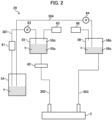
- Fig. 2 is a system diagram illustrating the configuration of a circulation device used in the inkjet recording apparatus according to the first embodiment.
- the circulation device 29 includes a main tank 54, a first sub tank 55, a second sub tank 56, a deaeration module 61, a filter 62, an air pressure controller 66, and the like.
- the main tank 54 and the first sub-tank 55 are connected to each other by a channel 301.
- the first sub-tank 55 and the inkjet head 2 are connected to each other by a channel 302.
- the inkjet head 2 and the second sub-tank 56 are connected to each other by a channel 303.
- the second sub tank 56 and the main tank 54 are connected to each other by a channel 304.
- the channels 301 to 304 are, for example, tube-shaped members through which the ink k passes.
- the inkjet head 2 ejects a part of the ink k supplied from the first sub-tank 55 from the ink nozzle 11, and discharges the remaining ink k to the second sub-tank 56.
- the main tank 54 stores the ink k to be circulated to each section of the circulation device 29.
- the first sub tank 55 stores the ink k supplied from the main tank 54, and the stored ink k is supplied to the inkjet head 2.
- the first sub-tank 55 is a tank-shaped container that is sealed except for various connection portions.
- the first sub-tank 55 has an ink layer 55a and an air layer 55b.
- the second sub-tank 56 stores the ink collected from the inkjet head 51.
- the second sub-tank 56 is a tank-shaped container which is sealed except for various connection portions.
- the second sub tank 56 has an ink layer 56a and an air layer 56b.
- a deaeration module 61 is provided in the channel 301.
- the deaeration module 61 performs deaeration of the ink k passing through the channel 301.
- the deaeration module 61 removes gasses dissolved in the ink k which is in contact with a gas permeable membrane through the gas permeable membrane. More specifically, the deaeration module 61 is configured in such a manner that the ink k is allowed to flow down to one side of the deaeration module 61 which is partitioned by the gas permeable membrane and the air pressure on the other side of the deaeration module 61 is reduced by a vacuum pump to remove the gasses dissolved in the ink k.
- the channel 302 is provided with the filter 62.
- the filter 62 removes foreign matters such as dust contained in the ink k passing through the channel 302. It is preferable that the diameter of the holes of the filter 62 is set such that the filter 62 is capable of removing foreign substances having a particle diameter equal to or greater than the nozzle diameter of the nozzles of the inkjet head 2.
- the channel 301 is provided with a pump 63.
- the pump 63 supplies the ink k from the main tank 54 to the first sub-tank 55.
- the pump 63 is a displacement pump such as a diaphragm pump, or a tube pump.
- the channel 304 is provided with a pump 64.
- the pump 64 supplies the ink k from the second sub-tank 56 to the main tank 54.
- the pump 64 is a displacement pump such as a diaphragm pump, or a tube pump.
- the air pressure controller 65 is connected to the first sub tank 55.
- the air pressure controller 65 is an actuator that adjusts the pressure of the air layer 55b in the first sub tank 55.
- the air pressure controller 66 is connected to the second sub tank 56.
- the air pressure controller 66 adjusts the pressure of the air layer 56b in the second sub-tank 56. Under the control of the air pressure controller 65 and the air pressure controller 66, it is possible to adjust the pressure of the ink k flowing from the first sub tank 55 to the inkjet head 2 and the pressure of the ink k flowing from the inkjet head 2 to the second sub tank 56.
- the ink k can be circulated by the differential pressure (circulation differential pressure) between the pressure of the inlet side and the pressure of the outlet side of the inkjet head 2, and the flow rate of the ink k in the inkjet head 2 can be adjusted. Furthermore, under the control of the air pressure controller 65 and the air pressure controller 66, the pressure in the ink nozzles 11 of the inkjet head 2 can be brought into the negative pressure state. As a result, it is possible to prevent the ink from leaking from the ink nozzles 11 when image formation and various kinds of maintenance works are not performed.
- the ink k is circulated in the order of the main tank 54-the first sub tank 55-the inkjet head 2-the second sub tank 56-the main tank 54.
- Such circulation of the ink k by the circulation device 29 is basically continued when the inkjet recording apparatus 1 is on standby, regardless of whether the image forming operation by the inkjet head 2 is being performed or the image forming operation is stopped.
- Fig. 3 is a longitudinal sectional view of a main part of the inkjet recording apparatus according to the first embodiment.
- the inkjet recording apparatus 1 includes a conveyance belt 31 on which an image forming medium c, which is an object on which an image is formed, such as a cloth or a sheet, is placed.
- the conveyance belt 31 conveys the image forming medium c in a sub-scanning direction (a direction perpendicular to the plane of Fig. 3 ).
- a carriage rail 32 Provided above the image forming medium c and the conveyance belt 31 is a carriage rail 32 whose longitudinal direction is a scanning direction (a main scanning direction. a horizontal direction in Fig. 3 ).
- the carriage 33 which is supported by the carriage rail 32 and moves in the longitudinal direction of the carriage rail 32 is also provided above the image forming medium c and the conveyance belt 31.
- the carriage 33 is provided with the inkjet head 2, and the inkjet head 2 is moved in a scanning direction by the carriage 33.
- a plurality of inkjet heads 2 corresponding to the respective colors of ink k are provided side by side in the scanning direction.
- a region 34 on the conveyance belt 31 is an area where the inkjet head 2 forms an image while moving.
- the maintenance section 35 is located outside of the area 34.
- the maintenance section 35 is a section where a predetermined maintenance work is performed on the inkjet head 2.
- the air blowing device 21 is arranged below the maintenance section 35 (e.g., a side of the conveyance belt 31).
- the air blowing device 21 blows air to the ink nozzle surface 11a of the inkjet head 2 positioned in the maintenance section 35.
- the air nozzles 22 are directed away from the image forming medium c side on the conveyance belt 31.
- the air nozzle 22 faces in a direction inclined from the region 34 side to the maintenance section 35 side.
- the air blowing device 21 blows off the mist and the foreign matters to the scanning direction side.
- a shield member 36 which is a wall-like member is provided in a predetermined region between the region 34 and the maintenance section 35.
- the shield member 36 serves as a shield that prevents foreign substances and mist blown off by the air of the air blowing device 21 from being adhered to the image forming medium c.
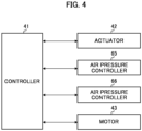
- Fig. 4 is a block diagram schematically illustrating electrical connection of a control system that executes the present control.
- the control system is mainly configured by a control device 41 (controller) configured by a microcomputer, and an application specific integrated circuit (ASIC).
- Various actuators such as the actuator 42 of the air blowing device 21, the air pressure controller 65 and 66, and the motor 43 serving as a driving source of the carriage 33, and various sensors are connected to the control device 41 via a predetermined interface.
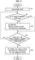
- Fig. 5 is a flowchart of control executed by the inkjet recording apparatus 1 of the first embodiment.
- the inkjet recording method of the present invention is performed.
- the circulation device 29 circulates the ink k through the route described above with reference to Fig. 2 .
- the controller 41 controls the air pressure controllers 65 and 66 to perform control such that the above-described circulation differential pressure of the ink k is equal to or less than the break pressure.
- the break pressure refers to a critical pressure for a meniscus of the ink k to be correctly formed.
- the flowchart of Fig. 5 illustrates control relating to air blowing by the air blowing device 21. Such a process is started at a timing when the carriage 33 starts to move from the maintenance section 35 to the region 34 side for the next scanning operation after one scanning operation of the carriage 33 (the inkjet head 2) is finished. That is, the processing of Fig. 5 is performed for each scan.
- the inkjet heads 2 of the inks k of the respective colors are generally provided side by side in the scanning direction on the carriage 33.
- the control device 41 performs a selection process of selecting the inkjet head 2 to which the air is blown by the air blowing device 21 (step S1).
- a process of selecting an inkjet head 2 whose use frequency is equal to or higher than a predetermined degree among the plurality of inkjet heads 2 is performed on the basis of image data for forming an image by the inkjet head 2.
- the carriage 33 has performed one scanning operation.
- How many ink droplets have been ejected from each inkjet head 2 for an image formed in the one scanning operation can be determined based on the image data.
- the inkjet head 2 whose frequency of use is higher than a predetermined level is selected as the inkjet head 2 to be blown with air.
- the step S 1 may be completed before starting the driving of the carriage 33 for the next scan.
- the controller 41 determines whether the inkjet head 2 selected in step S1 is at a predetermined position (step S2).
- the position each inkjet head 2 is currently present can be determined by the controller 41 based on the number of rotations of the motor 43.
- the predetermined position is a position at which the air from the air nozzle 22 is appropriately blown to each ink nozzle 11 of one inkjet head 2.
- the controller 41 controls the actuators 42 to blow air to the inkjet head 2 that has reached the predetermined position (Step S3).
- step S3 the controller 41 controls the air pressure controllers 65 and 66 to reduce the aforementioned circulation diffenrential pressure when the ink k is circulated compared to when the inkjet head 2 is driven to perform image formation (ejection of the ink k) (step S3).
- the air nozzles 22 are arranged as described above, when the inkjet head 2 moves for scanning, the foreign matters and the mist are blown off to the scanning direction side by the air.
- step S4 the controller 41 determines whether all of the inkjet heads 2 have passed the predetermined position. When there remains an inkjet head 2 that has not passed the predetermined position (no in step S4), the controller 41 returns to the processing in step S2. When the control device 41 determines that all the inkjet heads 2 have passed the predetermined position (Yes in step S4), the control device 41 returns the circulation differential pressure to the original value (step S5), and ends the process of Fig. 5 .
- control device 41 may control the actuator 42 to vary the velocity of the air blown from the air nozzle 22.
- the air speed of the air blown from the air nozzle 22 may be made faster than usual when the air is blown to the inkjet head 2.
- the controller 41 increases the speed of the air blown out from the nozzle 22, the controller 41 may increase the above-described circulation differential pressure greater than usual.
- the air blowing device 21 when the air blowing device 21 is blowing air, the aforementioned circulation differential pressure when the ink k is circulated is reduced compared to when the inkjet head 2 is driven to perform image formation (ejection of the ink k) (step S3). In this way, it is possible to suppress entrainment of air into the inkjet head 2 due to circulation of the ink k. Therefore, it is possible to sufficiently suppress the occurrence of defects in the ink discharge from the ink nozzles 11.
- the air blowing device 21 blows air when the inkjet head 2 is at a position (the maintenance section 35) other than the position (the region 34) where image formation is performed. Therefore, it is possible to prevents the mist or the foreign matter blown off by the air from adhering to the image forming medium c.
- the control device 41 increases the circulation differential pressure more than usual. Accordingly, it is possible to suppress the ink nozzle surface 11a from being excessively dried due to an increase in the wind velocity of the air.
- the shield member 36 due to the presence of the shield member 36, it is possible to prevent the mist and the foreign matter blown off by the air from adhering to the image forming medium c.
- the circulation differential pressure is equal to or less than the break pressure, the meniscus of the ink k can be correctly formed.
- the inkjet recording apparatus 1 performs the selection process (step S 1) to blow air only to the inkjet head 2 which has been frequently used (step S3). Therefore, it is possible to suppress drying of the ink nozzle 11 of the inkjet head 2 to which the mist or foreign matter does not seem to be adhered so much.
- the air blowing device 21 blows off foreign matter and mist to the scanning direction side by air when the inkjet head 2 moves for scanning. Therefore, it is possible to prevent the foreign matter or the like from being blown off in the sub-scanning direction to contaminate the image forming medium c. In addition, the mist and the foreign matter can be carefully removed from the ink nozzle surface 11a by blowing the air for each scan.
- the air nozzles 22 are directed away from the image forming medium c side, and the air blowing device 21 blows air when the carriage 33 moving the inkjet head 2 moves to the image forming medium c side. Therefore, it is possible to prevent the image forming medium c from being contaminated by the mist or the foreign substance blown off by the air.
- An inkjet recording apparatus is a single-pass inkjet recording apparatus.
- the inkjet recording apparatus is an apparatus which performs image formation with the inkjet head being fixed at a predetermined position.
- members common in the first embodiment will be denoted by common reference signs, and detailed description thereof will be omitted.
- all the configurations of the first embodiment which can be applied to the second embodiment are also provided in the second embodiment.
- Fig. 6 is a longitudinal cross-sectional view of the inkjet recording apparatus according to the second embodiment.
- the inkjet recording apparatus 401 includes a supply unit 410, an image forming unit 420, and an output unit 430.
- the supply section 410 supplies the image forming medium c on which an image is to be formed to the image forming unit 420.
- the supply section 410 includes a sheet feed tray 411 that holds the image forming medium c and a conveyance unit 412 that supplies the image forming medium c to the image forming unit 420.
- the sheet feed tray 411 is a plate-like member provided so that one or a plurality of image forming media c can be placed thereon.
- the sheet feed tray 411 is provided so as to move up and down in accordance with the amount of the placed image forming media c, and is held at a position where the uppermost image forming medium c is conveyed by the conveyance unit 412.
- the conveyance unit 412 feeds the uppermost one of the image forming media c placed on the sheet feed tray 411 onto a belt 123, and rotationally drives the belt 123 with rollers 121 and 122 to convey the image forming medium c on the belt 123.
- the image forming unit 420 forms an image by ejecting the ink k onto the image forming medium c supplied from the supply unit 410.
- the image forming unit 420 includes an image forming drum 421, a handover unit 422, a sheet heating unit 423, a head unit 424, an irradiator 425, and a delivery unit 426.
- the image forming drum 421 carries the image forming medium c along the cylindrical outer peripheral surface, and conveys the image forming medium c in accordance with the counterclockwise rotation of the image forming drum 421.
- the outer circumferential surface of the image forming drum 421 faces the sheet heating unit 423, the head units 424, and the irradiator 425.
- the handover unit 422 hands over the image forming medium c conveyed by the conveyance unit 412 to the image forming drum 421.
- the handover unit 422 includes a swing arm portion 221 that carries one end of the image forming medium c and a cylindrical handover drum 222.
- the handover unit 422 picks up the image forming medium c on the conveyance unit 412 with the swing arm section 221, guides the image forming medium c in a direction along the outer circumferential surface of the image forming drum 421 with the handover drum 222, and hands over the image forming medium c to the image forming drum 421.
- the sheet heating unit 423 heats the image forming medium c carried by the image forming drum 421.
- the sheet heating unit 423 includes, for example, an infrared heater that generates heat in response to energization.
- the sheet heating unit 423 is provided in the vicinity of the outer circumferential surface of the image forming drum 421 on the upstream side of the head unit 424 in the conveyance direction of the image forming medium c.
- the sheet heating unit 423 is controlled such that the image forming medium c carried by the image forming drum 421 and passing through the vicinity of the sheet heating unit 423 has a predetermined temperature.
- the head units 424 eject the ink k onto the image forming medium c carried on the image forming drum 421 to form an image.
- the plurality of head units 424, the four head units 424 in this example eject the different colors of ink k, respectively.
- a plurality of inkjet heads 2 are arranged in a row in the barrel length direction of the image forming drum 421 (the direction perpendicular to the paper surface of Fig. 6 ).
- the irradiator 425 irradiates the image forming medium c with energy rays for curing the ink k after the ink k has been ejected onto the image forming medium c.
- the irradiator 425 includes, for example, a fluorescent tube such as a low-pressure mercury lamp.
- the irradiator 425 is provided in the vicinity of the outer circumferential surface of the image forming drum 421 on the downstream side of the head unit 424 in the conveyance direction of the image forming medium c.
- the delivery unit 426 conveys the image forming medium c from the image forming drum 421 to the output unit 430.
- the delivery unit 426 delivers the image forming medium c carried by the image forming drum 421 to the belt 263 by the delivery drum 264.
- the delivery unit 426 rotationally drives the belt 263 by the rollers 261, 262 to carry the image forming medium c on the belt 263.
- the output unit 430 includes a sheet output tray 431 having a plate shape, and stores the image forming medium c conveyed from the image forming unit 420.
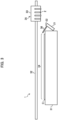
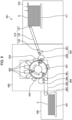
- Fig. 7 is a plan view of an air blowing device used in the second embodiment.
- Fig. 8 is a side view of the same.
- the air blowing device 451 includes a pair of rails 452 (a moving device). As illustrated in Fig. 8 , the rail 452 is curved in an arc shape so as to follow the arc shape of the outer periphery of the image forming drum 421 (for the sake of convenience, the rail is illustrated linearly in Fig. 7 ).
- a shaft-like nozzle support portion 453 is supported by the pair of rails 452.
- the nozzle support portion 453 is movable on the pair of rails 452 along the length direction of the rails 452 by driving of the motor 454.
- the nozzle support portion 453 is provided with a plurality of air nozzles 22 in a row in the length direction of the nozzle support portion 453. Each of the air nozzles 22 blows out air similarly to that in the first embodiment.
- Such a mechanism allows the plurality of air nozzles 22 (the nozzle support portion 453) to move in the space between the head unit 424 and the image forming drum 421 in the circumferential direction of the image forming drum 421 (the sub-scanning direction).
- the nozzle support portion 453 is movable in both forward and backward along the longitudinal direction of the rail 452. Therefore, the longitudinal direction of the nozzle support portion 453, which is the arrangement direction of the plurality of air nozzles 22, is a direction intersecting (orthogonal to) the sub-scanning direction.
- each of the air nozzles 22 faces each of the ink nozzles of a plurality of the inkjet heads 2 in the one of the head units 424 in an one on one manner.
- air can be blown from each of the air nozzles 22 to the each of the ink nozzle surfaces 11a of the plurality of the inkjet heads 2.
- the second embodiment also includes a circulation device 29 similar to the circulation device 29 of the first embodiment.
- a mechanism may be provided which retracts each head unit 424 from the image forming drum 421 side when the nozzle support portion 453 passes through the space.
- Fig. 6 illustrates a state in which a space between the head unit 424 and the image forming drum 421 is narrow during image formation.
- the rails 452 are provided at positions on both sides of the image forming drum 421 so as not to interfere with image formation.
- the nozzle support portion 453 retracts to a region where it does not interfere with the image formation.
- the nozzle support portion 453 is driven to blow air from each of the air nozzles 22 to each of the ink nozzle surfaces 11a of each inkjet head 2 of each head unit 424.
- the circulation device 29 is controlled to adjust the circulatory pressure difference in the same manner as in the first embodiment.
- a plurality of air nozzles 22 are provided on the nozzle support portion 453 so as to correspond to the arrangement of a plurality of the inkjet heads 2 in each head unit 424. Therefore, it is possible to blow air onto all of the plurality of inkjet heads 2 of each head unit 424.
Landscapes
- Ink Jet (AREA)
Applications Claiming Priority (1)
| Application Number | Priority Date | Filing Date | Title |
|---|---|---|---|
| JP2023092253A JP2024174435A (ja) | 2023-06-05 | 2023-06-05 | インクジェット記録装置およびインクジェット記録方法 |
Publications (1)
| Publication Number | Publication Date |
|---|---|
| EP4474155A1 true EP4474155A1 (de) | 2024-12-11 |
Family
ID=91330961
Family Applications (1)
| Application Number | Title | Priority Date | Filing Date |
|---|---|---|---|
| EP24178818.1A Pending EP4474155A1 (de) | 2023-06-05 | 2024-05-29 | Tintenstrahlaufzeichnungsvorrichtung und tintenstrahlaufzeichnungsverfahren |
Country Status (2)
| Country | Link |
|---|---|
| EP (1) | EP4474155A1 (de) |
| JP (1) | JP2024174435A (de) |
Citations (5)
| Publication number | Priority date | Publication date | Assignee | Title |
|---|---|---|---|---|
| JPH0416356A (ja) | 1990-05-10 | 1992-01-21 | Canon Inc | インクジェット記録装置 |
| JP5482517B2 (ja) * | 2010-07-05 | 2014-05-07 | セイコーエプソン株式会社 | ミスト回収装置、液体噴射装置及びミスト回収装置の制御方法 |
| JP2015066717A (ja) * | 2013-09-27 | 2015-04-13 | ブラザー工業株式会社 | 液体吐出装置 |
| US20160243857A1 (en) * | 2015-02-25 | 2016-08-25 | Riso Kagaku Corporation | Ink-jet printer |
| US20170087884A1 (en) * | 2015-09-24 | 2017-03-30 | Canon Kabushiki Kaisha | Printing apparatus and platen |
-
2023
- 2023-06-05 JP JP2023092253A patent/JP2024174435A/ja active Pending
-
2024
- 2024-05-29 EP EP24178818.1A patent/EP4474155A1/de active Pending
Patent Citations (5)
| Publication number | Priority date | Publication date | Assignee | Title |
|---|---|---|---|---|
| JPH0416356A (ja) | 1990-05-10 | 1992-01-21 | Canon Inc | インクジェット記録装置 |
| JP5482517B2 (ja) * | 2010-07-05 | 2014-05-07 | セイコーエプソン株式会社 | ミスト回収装置、液体噴射装置及びミスト回収装置の制御方法 |
| JP2015066717A (ja) * | 2013-09-27 | 2015-04-13 | ブラザー工業株式会社 | 液体吐出装置 |
| US20160243857A1 (en) * | 2015-02-25 | 2016-08-25 | Riso Kagaku Corporation | Ink-jet printer |
| US20170087884A1 (en) * | 2015-09-24 | 2017-03-30 | Canon Kabushiki Kaisha | Printing apparatus and platen |
Also Published As
| Publication number | Publication date |
|---|---|
| JP2024174435A (ja) | 2024-12-17 |
Similar Documents
| Publication | Publication Date | Title |
|---|---|---|
| JP5277506B2 (ja) | インクジェット記録ヘッド、インク貯留装置 | |
| JP5176570B2 (ja) | 記録装置および制御方法 | |
| JP2005119284A (ja) | 液滴吐出装置及び画像形成装置並びに予備吐出方法 | |
| EP1518683B1 (de) | Tröpfchenausstosskopf und Tintenstrahlaufzeichnungsgerät | |
| JP2009285845A (ja) | 印刷装置および印刷方法 | |
| JP5477981B2 (ja) | 液体吐出装置及びメンテナンス方法 | |
| JP6948133B2 (ja) | 液吸収装置、記録装置、記録方法および製造方法 | |
| US20180001644A1 (en) | Ink jet recording apparatus and cleaning method thereof | |
| JP3774902B2 (ja) | 液滴吐出ヘッド及びインクジェット記録装置 | |
| US11840078B2 (en) | Recording apparatus and method of controlling the same | |
| JP6824075B2 (ja) | 記録装置 | |
| US11827032B2 (en) | Image forming device, method, and storage medium | |
| JP2005125689A (ja) | インクジェットプリンタ | |
| JP2018130900A (ja) | 印刷装置、及び印刷装置の印刷方法 | |
| US20230096012A1 (en) | Liquid discharge apparatus and method for controlling liquid discharge apparatus | |
| JP2024174435A (ja) | インクジェット記録装置およびインクジェット記録方法 | |
| JP2012096463A (ja) | ヘッド洗浄装置及び画像形成装置並びにヘッド洗浄方法 | |
| JP7090500B2 (ja) | インクジェット記録装置およびその制御方法 | |
| JP2005231309A (ja) | 液吐出装置及び画像形成装置並びに気泡処理方法 | |
| JP2022011925A (ja) | 記録装置、制御方法及びプログラム | |
| JP2022048504A (ja) | インクジェット印刷装置 | |
| JP2009184122A (ja) | 記録装置および制御方法 | |
| JP2021107131A (ja) | 記録装置及び吸引ユニット | |
| JP2009126031A (ja) | インクジェット方式画像形成装置のインク吐出方法 | |
| JP2007276393A (ja) | インクジェット記録装置 |
Legal Events
| Date | Code | Title | Description |
|---|---|---|---|
| PUAI | Public reference made under article 153(3) epc to a published international application that has entered the european phase |
Free format text: ORIGINAL CODE: 0009012 |
|
| STAA | Information on the status of an ep patent application or granted ep patent |
Free format text: STATUS: THE APPLICATION HAS BEEN PUBLISHED |
|
| AK | Designated contracting states |
Kind code of ref document: A1 Designated state(s): AL AT BE BG CH CY CZ DE DK EE ES FI FR GB GR HR HU IE IS IT LI LT LU LV MC ME MK MT NL NO PL PT RO RS SE SI SK SM TR |
|
| P01 | Opt-out of the competence of the unified patent court (upc) registered |
Free format text: CASE NUMBER: APP_66438/2024 Effective date: 20241216 |
|
| STAA | Information on the status of an ep patent application or granted ep patent |
Free format text: STATUS: REQUEST FOR EXAMINATION WAS MADE |
|
| 17P | Request for examination filed |
Effective date: 20250515 |
|
| STAA | Information on the status of an ep patent application or granted ep patent |
Free format text: STATUS: EXAMINATION IS IN PROGRESS |