EP4471972A2 - Sekundärbatterie mit einer auf der innenfläche des batteriegehäuses geformten leitfähigen schicht - Google Patents
Sekundärbatterie mit einer auf der innenfläche des batteriegehäuses geformten leitfähigen schicht Download PDFInfo
- Publication number
- EP4471972A2 EP4471972A2 EP24207789.9A EP24207789A EP4471972A2 EP 4471972 A2 EP4471972 A2 EP 4471972A2 EP 24207789 A EP24207789 A EP 24207789A EP 4471972 A2 EP4471972 A2 EP 4471972A2
- Authority
- EP
- European Patent Office
- Prior art keywords
- secondary battery
- electrode assembly
- case
- conductive
- electrolyte solution
- Prior art date
- Legal status (The legal status is an assumption and is not a legal conclusion. Google has not performed a legal analysis and makes no representation as to the accuracy of the status listed.)
- Pending
Links
Images

Classifications
-
- H—ELECTRICITY
- H01—ELECTRIC ELEMENTS
- H01M—PROCESSES OR MEANS, e.g. BATTERIES, FOR THE DIRECT CONVERSION OF CHEMICAL ENERGY INTO ELECTRICAL ENERGY
- H01M50/00—Constructional details or processes of manufacture of the non-active parts of electrochemical cells other than fuel cells, e.g. hybrid cells
- H01M50/10—Primary casings; Jackets or wrappings
- H01M50/116—Primary casings; Jackets or wrappings characterised by the material
- H01M50/124—Primary casings; Jackets or wrappings characterised by the material having a layered structure
- H01M50/1243—Primary casings; Jackets or wrappings characterised by the material having a layered structure characterised by the internal coating on the casing
-
- H—ELECTRICITY
- H01—ELECTRIC ELEMENTS
- H01M—PROCESSES OR MEANS, e.g. BATTERIES, FOR THE DIRECT CONVERSION OF CHEMICAL ENERGY INTO ELECTRICAL ENERGY
- H01M10/00—Secondary cells; Manufacture thereof
- H01M10/04—Construction or manufacture in general
- H01M10/0422—Cells or battery with cylindrical casing
- H01M10/0427—Button cells
-
- H—ELECTRICITY
- H01—ELECTRIC ELEMENTS
- H01M—PROCESSES OR MEANS, e.g. BATTERIES, FOR THE DIRECT CONVERSION OF CHEMICAL ENERGY INTO ELECTRICAL ENERGY
- H01M10/00—Secondary cells; Manufacture thereof
- H01M10/04—Construction or manufacture in general
- H01M10/0431—Cells with wound or folded electrodes
-
- H—ELECTRICITY
- H01—ELECTRIC ELEMENTS
- H01M—PROCESSES OR MEANS, e.g. BATTERIES, FOR THE DIRECT CONVERSION OF CHEMICAL ENERGY INTO ELECTRICAL ENERGY
- H01M10/00—Secondary cells; Manufacture thereof
- H01M10/04—Construction or manufacture in general
- H01M10/0468—Compression means for stacks of electrodes and separators
-
- H—ELECTRICITY
- H01—ELECTRIC ELEMENTS
- H01M—PROCESSES OR MEANS, e.g. BATTERIES, FOR THE DIRECT CONVERSION OF CHEMICAL ENERGY INTO ELECTRICAL ENERGY
- H01M50/00—Constructional details or processes of manufacture of the non-active parts of electrochemical cells other than fuel cells, e.g. hybrid cells
- H01M50/10—Primary casings; Jackets or wrappings
- H01M50/102—Primary casings; Jackets or wrappings characterised by their shape or physical structure
- H01M50/103—Primary casings; Jackets or wrappings characterised by their shape or physical structure prismatic or rectangular
-
- H—ELECTRICITY
- H01—ELECTRIC ELEMENTS
- H01M—PROCESSES OR MEANS, e.g. BATTERIES, FOR THE DIRECT CONVERSION OF CHEMICAL ENERGY INTO ELECTRICAL ENERGY
- H01M50/00—Constructional details or processes of manufacture of the non-active parts of electrochemical cells other than fuel cells, e.g. hybrid cells
- H01M50/10—Primary casings; Jackets or wrappings
- H01M50/102—Primary casings; Jackets or wrappings characterised by their shape or physical structure
- H01M50/107—Primary casings; Jackets or wrappings characterised by their shape or physical structure having curved cross-section, e.g. round or elliptic
-
- H—ELECTRICITY
- H01—ELECTRIC ELEMENTS
- H01M—PROCESSES OR MEANS, e.g. BATTERIES, FOR THE DIRECT CONVERSION OF CHEMICAL ENERGY INTO ELECTRICAL ENERGY
- H01M50/00—Constructional details or processes of manufacture of the non-active parts of electrochemical cells other than fuel cells, e.g. hybrid cells
- H01M50/10—Primary casings; Jackets or wrappings
- H01M50/102—Primary casings; Jackets or wrappings characterised by their shape or physical structure
- H01M50/109—Primary casings; Jackets or wrappings characterised by their shape or physical structure of button or coin shape
-
- H—ELECTRICITY
- H01—ELECTRIC ELEMENTS
- H01M—PROCESSES OR MEANS, e.g. BATTERIES, FOR THE DIRECT CONVERSION OF CHEMICAL ENERGY INTO ELECTRICAL ENERGY
- H01M50/00—Constructional details or processes of manufacture of the non-active parts of electrochemical cells other than fuel cells, e.g. hybrid cells
- H01M50/10—Primary casings; Jackets or wrappings
- H01M50/116—Primary casings; Jackets or wrappings characterised by the material
- H01M50/117—Inorganic material
- H01M50/119—Metals
-
- H—ELECTRICITY
- H01—ELECTRIC ELEMENTS
- H01M—PROCESSES OR MEANS, e.g. BATTERIES, FOR THE DIRECT CONVERSION OF CHEMICAL ENERGY INTO ELECTRICAL ENERGY
- H01M50/00—Constructional details or processes of manufacture of the non-active parts of electrochemical cells other than fuel cells, e.g. hybrid cells
- H01M50/10—Primary casings; Jackets or wrappings
- H01M50/116—Primary casings; Jackets or wrappings characterised by the material
- H01M50/121—Organic material
-
- H—ELECTRICITY
- H01—ELECTRIC ELEMENTS
- H01M—PROCESSES OR MEANS, e.g. BATTERIES, FOR THE DIRECT CONVERSION OF CHEMICAL ENERGY INTO ELECTRICAL ENERGY
- H01M50/00—Constructional details or processes of manufacture of the non-active parts of electrochemical cells other than fuel cells, e.g. hybrid cells
- H01M50/10—Primary casings; Jackets or wrappings
- H01M50/147—Lids or covers
- H01M50/166—Lids or covers characterised by the methods of assembling casings with lids
-
- H—ELECTRICITY
- H01—ELECTRIC ELEMENTS
- H01M—PROCESSES OR MEANS, e.g. BATTERIES, FOR THE DIRECT CONVERSION OF CHEMICAL ENERGY INTO ELECTRICAL ENERGY
- H01M50/00—Constructional details or processes of manufacture of the non-active parts of electrochemical cells other than fuel cells, e.g. hybrid cells
- H01M50/10—Primary casings; Jackets or wrappings
- H01M50/183—Sealing members
- H01M50/184—Sealing members characterised by their shape or structure
-
- H—ELECTRICITY
- H01—ELECTRIC ELEMENTS
- H01M—PROCESSES OR MEANS, e.g. BATTERIES, FOR THE DIRECT CONVERSION OF CHEMICAL ENERGY INTO ELECTRICAL ENERGY
- H01M50/00—Constructional details or processes of manufacture of the non-active parts of electrochemical cells other than fuel cells, e.g. hybrid cells
- H01M50/10—Primary casings; Jackets or wrappings
- H01M50/183—Sealing members
- H01M50/186—Sealing members characterised by the disposition of the sealing members
-
- H—ELECTRICITY
- H01—ELECTRIC ELEMENTS
- H01M—PROCESSES OR MEANS, e.g. BATTERIES, FOR THE DIRECT CONVERSION OF CHEMICAL ENERGY INTO ELECTRICAL ENERGY
- H01M50/00—Constructional details or processes of manufacture of the non-active parts of electrochemical cells other than fuel cells, e.g. hybrid cells
- H01M50/40—Separators; Membranes; Diaphragms; Spacing elements inside cells
- H01M50/409—Separators, membranes or diaphragms characterised by the material
- H01M50/411—Organic material
- H01M50/414—Synthetic resins, e.g. thermoplastics or thermosetting resins
- H01M50/417—Polyolefins
-
- H—ELECTRICITY
- H01—ELECTRIC ELEMENTS
- H01M—PROCESSES OR MEANS, e.g. BATTERIES, FOR THE DIRECT CONVERSION OF CHEMICAL ENERGY INTO ELECTRICAL ENERGY
- H01M50/00—Constructional details or processes of manufacture of the non-active parts of electrochemical cells other than fuel cells, e.g. hybrid cells
- H01M50/40—Separators; Membranes; Diaphragms; Spacing elements inside cells
- H01M50/471—Spacing elements inside cells other than separators, membranes or diaphragms; Manufacturing processes thereof
- H01M50/474—Spacing elements inside cells other than separators, membranes or diaphragms; Manufacturing processes thereof characterised by their position inside the cells
-
- H—ELECTRICITY
- H01—ELECTRIC ELEMENTS
- H01M—PROCESSES OR MEANS, e.g. BATTERIES, FOR THE DIRECT CONVERSION OF CHEMICAL ENERGY INTO ELECTRICAL ENERGY
- H01M50/00—Constructional details or processes of manufacture of the non-active parts of electrochemical cells other than fuel cells, e.g. hybrid cells
- H01M50/40—Separators; Membranes; Diaphragms; Spacing elements inside cells
- H01M50/471—Spacing elements inside cells other than separators, membranes or diaphragms; Manufacturing processes thereof
- H01M50/48—Spacing elements inside cells other than separators, membranes or diaphragms; Manufacturing processes thereof characterised by the material
- H01M50/483—Inorganic material
-
- H—ELECTRICITY
- H01—ELECTRIC ELEMENTS
- H01M—PROCESSES OR MEANS, e.g. BATTERIES, FOR THE DIRECT CONVERSION OF CHEMICAL ENERGY INTO ELECTRICAL ENERGY
- H01M50/00—Constructional details or processes of manufacture of the non-active parts of electrochemical cells other than fuel cells, e.g. hybrid cells
- H01M50/50—Current conducting connections for cells or batteries
- H01M50/572—Means for preventing undesired use or discharge
- H01M50/574—Devices or arrangements for the interruption of current
- H01M50/578—Devices or arrangements for the interruption of current in response to pressure
-
- H—ELECTRICITY
- H01—ELECTRIC ELEMENTS
- H01M—PROCESSES OR MEANS, e.g. BATTERIES, FOR THE DIRECT CONVERSION OF CHEMICAL ENERGY INTO ELECTRICAL ENERGY
- H01M4/00—Electrodes
- H01M4/02—Electrodes composed of, or comprising, active material
- H01M2004/026—Electrodes composed of, or comprising, active material characterised by the polarity
- H01M2004/027—Negative electrodes
-
- H—ELECTRICITY
- H01—ELECTRIC ELEMENTS
- H01M—PROCESSES OR MEANS, e.g. BATTERIES, FOR THE DIRECT CONVERSION OF CHEMICAL ENERGY INTO ELECTRICAL ENERGY
- H01M4/00—Electrodes
- H01M4/02—Electrodes composed of, or comprising, active material
- H01M2004/026—Electrodes composed of, or comprising, active material characterised by the polarity
- H01M2004/028—Positive electrodes
-
- H—ELECTRICITY
- H01—ELECTRIC ELEMENTS
- H01M—PROCESSES OR MEANS, e.g. BATTERIES, FOR THE DIRECT CONVERSION OF CHEMICAL ENERGY INTO ELECTRICAL ENERGY
- H01M50/00—Constructional details or processes of manufacture of the non-active parts of electrochemical cells other than fuel cells, e.g. hybrid cells
- H01M50/30—Arrangements for facilitating escape of gases
- H01M50/342—Non-re-sealable arrangements
-
- Y—GENERAL TAGGING OF NEW TECHNOLOGICAL DEVELOPMENTS; GENERAL TAGGING OF CROSS-SECTIONAL TECHNOLOGIES SPANNING OVER SEVERAL SECTIONS OF THE IPC; TECHNICAL SUBJECTS COVERED BY FORMER USPC CROSS-REFERENCE ART COLLECTIONS [XRACs] AND DIGESTS
- Y02—TECHNOLOGIES OR APPLICATIONS FOR MITIGATION OR ADAPTATION AGAINST CLIMATE CHANGE
- Y02E—REDUCTION OF GREENHOUSE GAS [GHG] EMISSIONS, RELATED TO ENERGY GENERATION, TRANSMISSION OR DISTRIBUTION
- Y02E60/00—Enabling technologies; Technologies with a potential or indirect contribution to GHG emissions mitigation
- Y02E60/10—Energy storage using batteries
-
- Y—GENERAL TAGGING OF NEW TECHNOLOGICAL DEVELOPMENTS; GENERAL TAGGING OF CROSS-SECTIONAL TECHNOLOGIES SPANNING OVER SEVERAL SECTIONS OF THE IPC; TECHNICAL SUBJECTS COVERED BY FORMER USPC CROSS-REFERENCE ART COLLECTIONS [XRACs] AND DIGESTS
- Y02—TECHNOLOGIES OR APPLICATIONS FOR MITIGATION OR ADAPTATION AGAINST CLIMATE CHANGE
- Y02P—CLIMATE CHANGE MITIGATION TECHNOLOGIES IN THE PRODUCTION OR PROCESSING OF GOODS
- Y02P70/00—Climate change mitigation technologies in the production process for final industrial or consumer products
- Y02P70/50—Manufacturing or production processes characterised by the final manufactured product
Definitions
- the present disclosure relates to a secondary battery having a conductive layer formed on the inner surface of a battery case.
- a secondary battery is a representative example of an electrochemical device that utilizes such electrochemical energy, and the range of use thereof tends to be gradually expanding.
- the secondary battery has a structure in which an electrode assembly comprising a positive electrode, a negative electrode, and a porous separator is built into in a battery case in a state of being impregnated with a non-aqueous electrolyte.
- a secondary battery may be generally classified as a cylindrical secondary battery or a prismatic secondary battery in which a stacked/folded type, or wound type electrode assembly is housed in a case made of metal as a battery case, a pouch type secondary battery in which a stacked type or stacked/folding type electrode assembly is built into a pouch type battery case made of an aluminum laminate sheet, and a coin-type secondary battery in which a coin-type electrode assembly is housed in an upper case and a lower case made of metal.
- the exterior material of the cylindrical, prismatic, or coin-type secondary battery i.e., the battery case, is generally made of metal, especially stainless steel (SUS).
- SUS stainless steel
- the present disclosure has been made to solve the above-mentioned problems and other technical problems that have yet to be resolved.
- an object of the present disclosure is to provide a secondary battery that can effectively suppress the corrosion of the secondary battery case due to contact with the electrolyte.
- a secondary battery configured such that an electrode assembly including a positive electrode, a separator, and a negative electrode is housed in a battery case together with an electrolyte solution, wherein the battery case is made of metal, and a conductive layer made of one selected from the group consisting of a conductive carbon layer, a conductive polymer layer, and a conductive epoxy layer is formed on a part or the whole of the inner surface of the battery case coming into contact with the electrolyte solution.
- the secondary battery further comprises a spring and a spacer that fill an inner space excluding the electrode assembly in the inside of the first case and the second case,
- the secondary battery may further comprise a gasket for sealing the first case and the second case.
- the secondary battery is a cylindrical secondary battery
- a gasket is mounted on the upper part of the beading part of the cylindrical can,
- the electrode assembly is a jelly-roll type or stack/folding type electrode assembly
- the electrode assembly comprises a positive electrode tab and a negative electrode tab drawn out from the electrode assembly, wherein the positive tab and the negative tab are respectively connected to the cap terminals, and a conductive layer may be formed on the inside surface of the secondary battery, in at least one member selected from the group consisting of the positive electrode tab and the negative electrode tab.
- the metal may be made of any one selected from the group consisting of aluminum, nickel, stainless steel (SUS), copper, iron, bronze, and brass.
- the secondary battery may further comprise a hollow center pin inserted into the center of the electrode assembly.
- the conductive layer may be formed to a thickness of 0.01 ⁇ m to 100 ⁇ m.
- the conductive carbon layer may comprise graphene and a binder polymer.
- the conductive polymer layer may comprise at least one conductive polymer selected from the group consisting of poly(3,4-ethylenedioxythiophene)/poly(4-styrene sulfonate (PEDOT/PSS), polyaniline (PANI), polypyrrole (PPy), polythiophene (PT), polyacetylene (PA), and poly para-phenylene vinylene (PPV).
- PEDOT/PSS polyaniline
- PANI polypyrrole
- PT polythiophene
- PA polyacetylene
- PV poly para-phenylene vinylene
- the conductive epoxy layer may comprise at least one conductive filler selected from the group consisting of gold, platinum, silver, copper, or nickel metal powder, carbon or carbon fiber, graphite, and composite powder, and an epoxy polymer.
- a secondary battery configured such that an electrode assembly including a positive electrode, a separator, and a negative electrode is housed in a battery case together with an electrolyte solution, wherein the battery case is made of metal, and a conductive layer made of one selected from the group consisting of a conductive carbon layer, a conductive polymer layer, and a conductive epoxy layer is formed on a part or the whole of the inner surface of the battery case coming into contact with the electrolyte solution.
- the position where the conductive layer is formed may differ depending on the type of secondary battery.
- the conductive layer may be formed on a surface coming into contact with an electrolyte solution, and more specifically, the conductive layer may be formed at a position at which it should have conductivity while coming into contact with the electrolyte solution.
- the secondary battery may be a coin-type secondary battery
- the secondary battery further comprises a spring and a spacer that fill an inner space excluding the electrode assembly in the inside of the first case and the second case,
- the first case, the second case, the spring, and the spacer are made of metal, and the degree of corrosion is severe depending on what kind of material is used as the electrolyte solution, the lifespan characteristics are deteriorated, or it will be unusable any more or the safety may be threatened.
- a conductive layer can be formed on a surface where the first case, the second case, the spring, and the spacer come into contact with the electrolyte, thereby preventing corrosion due to the electrolyte solution while having conductivity.
- the secondary battery may further include a gasket for sealing the first case and the second case.
- the gasket is generally made of an insulating material and thus, the conductive layer need not be formed. However, the conductive layer may also be formed on a surface of the gasket, and such a structure is not excluded.
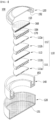
- a perspective view of a coin-type secondary battery having such a conductive layer formed therein is shown in Fig. 1
- a schematic diagram of the cross section is shown in Fig. 2 .
- the coin-type secondary battery 100 of the present disclosure includes an electrode assembly 110; a first case 120 for housing the electrode assembly 110; a second case 130 assembled so as to cover the upper end of the first case 120; and a spring 160 and a spacer 170 that fill an inner space excluding the electrode assembly in the inside of the first case and the second case.
- the electrode assembly 110 includes a positive electrode 111, a negative electrode 112, and a separator 113 interposed between the positive electrode 111 and the negative electrode 112, wherein the positive electrode 111, the negative electrode 112 and the separator 113 have a coin-type structure.
- first case 120, the second case 130, the spring 160 and the spacer 170 are made of metal and thus, in order to prevent corrosion due to the reaction with an electrolyte solution, conductive layers 151, 152, 153 and 154 made of one selected from the group consisting of a conductive carbon layer, a conductive polymer layer, and a conductive epoxy layer are formed on a surface coming into contact with the electrolyte solution, respectively.
- the coin-type secondary battery 100 may further include a gasket 140 for sealing the first case 120 and the second case 130.
- the conductive layers 151, 152, 153 and 154 preferably include a material having conductivity, considering that the cases, spring and spacer of the coin-type secondary battery are made of metal, and these themselves serve as electrode terminals.
- the conductive layers 151 , 152 , 153 and 154 are formed wholly on the inner surface of the case, ensuring conductivity as much as corrosion is prevented is a very important issue. Even if the corrosion is prevented, the performance as a secondary battery will be eventually deteriorated if the conductivity is not sufficiently secured, and thus there is no choice but to lose the meaning of the invention.
- the conductive layers 151 , 152 , 153 and 154 may be made of one selected from the group consisting of a conductive carbon layer, a conductive polymer layer, and a conductive epoxy layer.
- the secondary battery is a cylindrical secondary battery
- a gasket is mounted on the upper part of the beading part of the cylindrical can,
- the bottom part of the cylindrical can and the components of the cap assembly are made of metal, and the degree of corrosion is severe depending on what kind of material is used as the electrolyte solution, the lifespan characteristics are deteriorated, or it will be unusable any more or the safety may be threatened.
- the components necessarily require conductivity.
- a conductive layer can be formed on a surface where the components come into contact with the electrolyte solution, thereby preventing corrosion due to the electrolyte solution while having conductivity.
- the housing part, the beading part, and the gasket excluding the bottom surface of the cylindrical can do not necessarily require conductivity as described above, and thus the conductive layer does not need to be formed.
- a conductive layer may also be formed on the surfaces of these components, and such a structure is not excluded.
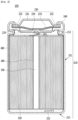
- a perspective view of a cylindrical secondary battery in which such a conductive layer is formed is shown in Fig. 3 below.
- the secondary battery 200 is structured such that an electrode assembly 120 including a positive electrode, a separator, and a negative electrode is housed together with an electrolyte solution in a cylindrical can 210 including a housing part 211 and a beading part 212 as a battery case, wherein a cap assembly 230 including the upper end cap 231 is located at the opened upper end part of the cylindrical can 210 and seals the cylindrical can 210.
- the electrode assembly 220 may be a jelly-roll type or a stack/folding type electrode assembly, without being limited thereto.
- the jelly-roll type electrode assembly is manufactured by interposing a sheet-type separator between a sheet-type positive electrode and a sheet-type negative electrode and winding it.
- the stack/folding type electrode assembly is manufactured by arranging a unit electrode, a full cell stacked so that electrodes having the same polarity are located at both ends, and a bi-cell stacked so that electrodes having different polarities are located at both ends, on a sheet-type separation film, and winding the same.
- the secondary battery 200 includes a gasket 240 mounted on the upper end part of the beading part 212 of the cylindrical can 210, and is formed in a structure in which the cap assembly 230 includes an upper end cap 231, a current interruption safety device (PTC device, 232) stacked under the upper end cap 231 and a safety vent 233 for internal pressure drop, and a current interruption device (CID) 234 formed at the lower end of the safety vent 233.
- PTC device current interruption safety device
- CID current interruption device
- the positive electrode tab 221 and the negative electrode tab 222 are drawn out from the electrode assembly 220, the positive electrode tab 221 is connected to the cap assembly 230, and the negative electrode tab 222 is connected to a bottom surface 213 spaced apart from a housing part 211 of the cylindrical can 230.
- the current interruption safety device 232, the safety vent 233, and the current interruption device 234 all are preferably structures through which current flows, which are formed in order to ensure the safety of the secondary battery.
- the current interruption safety device 232, the safety vent 233, the current interruption device 234, as well as the upper end cap 231 serving as a positive electrode terminal, the bottom surface 213 of the cylindrical can 210 serving as a negative electrode terminal, and the positive electrode tab 221 and the negative electrode tab 222 preferably have conductivity. Therefore, a conductive layer 170 may be formed on the inside surface of the secondary battery 100 in order to prevent corrosion due to leakage of the electrolyte solution while maintaining conductivity, in which the secondary battery 100 includes the upper end cap 131, the bottom surface 113 of the cylindrical can, the current interruption safety device 132, the safety vent 133, the current interruption device 134, the positive electrode tab 121, and the negative electrode tab 122.
- the conductive layer 170 may be formed wholly on the surface of the above members exposed inside the secondary battery, but may be formed only on a surface toward the electrode assembly in each member.
- a conductive layer for corrosion prevention may be formed on the housing part 211, the beading part 212, and the gasket 140 excluding the bottom surface 213 of the cylindrical can 210, without being limited thereto, or the above components do not necessarily require conductivity, and thus other anti-corrosion layers 160 may be formed.
- the secondary battery 200 may further include a hollow center pin 250 inserted into the center of the jelly-roll type electrode assembly 220.
- the center pin 250 may also be made of any one selected from the group consisting of metal, specifically aluminum, nickel, stainless steel (SUS), copper, iron, bronze, and brass, which thus causes corrosion to the electrolyte.
- metal specifically aluminum, nickel, stainless steel (SUS), copper, iron, bronze, and brass, which thus causes corrosion to the electrolyte.
- SUS stainless steel
- copper iron, bronze, and brass
- the conductivity is not necessarily required.
- a conductive layer may be formed, other anti-corrosion layers 280 may be additionally formed, and more specifically, the anti-corrosion layer 280 may be formed up to the hollow inner surface.
- the conductive layer 270 may be formed at a portion that is likely to come into contact with the electrolyte solution, whereby the conductivity may not be lowered while effectively preventing corrosion due to contact with the electrolyte solution, which is thus more preferable.
- the secondary battery is a prismatic secondary battery
- the electrode assembly comprises a positive electrode tab and a negative electrode tab drawn out from the electrode assembly, wherein the positive tab and the negative tab are respectively connected to the cap terminals, and a conductive layer is formed on the inside surface of the secondary battery, in at least one member selected from the group consisting of the positive electrode tab and the negative electrode tab.
- the inner surface of the cap terminals of the top cap, the positive electrode tab, and the negative electrode tab are made of metal, and the degree of corrosion is severe depending on what kind of material is used as the electrolyte solution, the lifespan characteristics are deteriorated, or it will be unusable any more or the safety may be threatened.
- these components necessarily require conductivity.
- a conductive layer can be formed on a surface where the components come into contact with the electrolyte solution, thereby preventing corrosion due to the electrolyte solution while having conductivity.
- the can body, the portion excluding the cap terminals of the top cap, and the gasket do not necessarily require conductivity, and thus the conductive layer does not need to be formed.
- a conductive layer may be formed even on the surface of these components, and such a structure is not excluded.
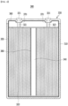
- a perspective view of a prismatic secondary battery in which such a conductive layer is formed is shown in Fig. 4 below.
- the secondary battery 300 comprises a rectangular can body 310 that is opened in its upper end and houses the electrode assembly 320 and the electrolyte solution together, and a top cap 330 including cap terminals 331 that are coupled and sealed to the upper end part of the can body 310 and are connected to the electrode terminals 321 and 322 of the electrode assembly 320.
- the electrode assembly 320 is the same as those described for the cylindrical secondary battery.
- the electrode assembly 320 includes a positive electrode tab 321 and a negative electrode tab 322 drawn upward from the electrode assembly 320, and the positive electrode tab 321 and the negative electrode tab 322 are respectively connected to the can terminals 331.
- a conductive layer 270 made of one selected from the group consisting of a conductive carbon layer, a conductive polymer layer, and a conductive epoxy layer are formed on the inside surface of the secondary battery 300.
- a conductive layer for corrosion prevention may be formed on the portion excluding the cap terminals 331 of the prismatic can body 310 and the top cap 330, without being limited thereto, or the components do not necessarily require conductivity and thus, other anti-corrosion layers 250 and 260 may be formed.
- the secondary battery 300 may further include a hollow center pin 340 inserted into the center of the jelly-roll type electrode assembly 320.
- the center pin 340 may also made of metal, specifically any one selected from the group consisting of aluminum, nickel, stainless steel (SUS), copper, iron, bronze, and brass, which thus causes corrosion to the electrolyte solution.
- SUS stainless steel
- the conductivity is not necessarily required.
- a conductive layer may also be formed on the outer surface coming into contact with an electrolyte solution in the center pin 350, other anti-corrosion layers 380 may be additionally formed, and more specifically, the anti-corrosion layer 380 may be formed up to the hollow inner surface.
- the conductive layer may have a thickness of 0.01 ⁇ m to 100 ⁇ m, specifically 0.5 ⁇ m to 30 ⁇ m, and more specifically, 1 ⁇ m to 10 ⁇ m.
- the conductive layer is too thin outside the above range, it cannot exhibit a sufficient anti-corrosion effect, and if the conductive layer is too thick, the conductivity may be lowered or the bulk energy density may be lowered, which is thus not preferable.
- the metals constituting the above components may be made of any one selected from the group consisting of aluminum, nickel, stainless steel (SUS), copper, iron, bronze, and brass, and specifically, it may be made of aluminum or stainless steel (SUS), and more specifically, it may be made of stainless steel (SUS).
- the conductive layer should have conductivity as described above, it may be made of, specifically, one selected from the group consisting of a conductive carbon layer, a conductive polymer layer, and a conductive epoxy layer.
- the conductive carbon layer may include graphene as a carbon-based material rather than a general carbon material, and further include a binder polymer.
- the graphene When using the graphene, it can exhibit superior conductivity compared to the case of using other carbon-based materials. According to the present disclosure, for a coin-type secondary battery, ensuring conductivity is an important factor, and thus it is essential to ensure sufficient conductivity. Otherwise, the secondary battery performance may be deteriorated, and thus it is important to use graphene exhibiting most excellent conductivity among carbon-based materials.
- the binder polymer is used for bonding between a metal member and a conductive carbon layer, and is not limited as long as it has a general binding component, and examples thereof may be at least one selected from the group consisting of polyvinylidene fluoride, polyvinyl alcohol, carboxymethylcellulose (CMC), starch, hydroxypropylcellulose, regenerated cellulose, polyvinylpyrrolidone, tetrafluoroethylene, polyethylene, polypropylene, ethylene-propylene-diene terpolymer (EPDM), sulfonated EPDM, styrene butylene rubber, and fluorine rubber.
- CMC carboxymethylcellulose
- EPDM ethylene-propylene-diene terpolymer
- EPDM ethylene-propylene-diene terpolymer
- the graphene and the binder polymer may be contained in a weight ratio of 1:99 to 99: 1, and specifically in a weight ratio of 3:7 to 7:3.
- the conductive carbon layer can be formed by using a wet coating method such as gravure coating, slot die coating, spin coating, spray coating, bar coating and dip coating, or a dry coating method such as thermal evaporation, E-beam evaporation, chemical vapor deposition, and sputtering.
- a wet coating method such as gravure coating, slot die coating, spin coating, spray coating, bar coating and dip coating
- a dry coating method such as thermal evaporation, E-beam evaporation, chemical vapor deposition, and sputtering.
- the conductive polymer layer may include at least one conductive polymer selected from the group consisting of poly(3,4-ethylenedioxythiophene)/poly(4-styrene sulfonate) (PEDOT/PSS), polyaniline (PANI), polypyrrole (PPy), polythiophene (PT), polyacetylene (PA), and poly para-phenylene vinylene (PPV).
- PEDOT/PSS polyaniline
- PANI polypyrrole
- PT polythiophene
- PA polyacetylene
- PV poly para-phenylene vinylene
- the conductive polymer layer may be formed by preparing a conductive polymer melt or a mixed solution in which these are dissolved in a solvent, and subjecting it to various wet coating methods as described in the coating method of the conductive carbon layer.
- the solvent may be a polar organic solvent, and for example, chloroform, dichloromethane, m-cresol, tetrahydrofuran (THF), and dimethylformamide (DMF) and the like may be mentioned.
- the conductive polymer does not require a separate binder material and the like because the polymer itself exhibits a binding force.
- it may additionally include a binder polymer as disclosed in the conductive carbon layer, wherein the content thereof may be 0.1 to 10% by weight based on the total weight of the conductive polymer layer.
- the conductive epoxy layer may include a conductive filler and an epoxy polymer.
- the conductive filler may be at least one selected from the group consisting of metal powders of gold, platinum, silver, copper, or nickel, carbon or carbon fibers, graphite, and composite powder.
- the epoxy polymer is a component that binds the conductive filler, and examples thereof may be at least one selected from the group consisting of acrylic-based, epoxy-based, polyurethane-based, silicon-based, polyimide-based, phenolic-based, polyester-based polymer materials, composite polymer resins and low melting point glass, without being limited thereto.
- the conductive epoxy layer may be classified into a room-temperature drying type, a room-temperature curing type, a heat-curing type, a high-temperature sintering type, and a UV curing type, based on the production method.
- the room-temperature drying type may be formed by incorporating a conductive filler into an acrylic polymer such as acrylic-based and a solvent, and drying it at room temperature
- the room-temperature curing type is a two-component type and may be formed by additionally containing a highly reactive curing agent and curing a solvent containing a conductive filler and an epoxy polymer.
- the heat-curing type can be formed by applying heat to a solvent containing a conductive filler, mainly using an epoxy-based epoxy polymer, and the high-temperature sintering type can be formed by curing by heat treatment at a high temperature, and the UV-curable type can be formed by curing by the irradiation with UV.
- the conductive filler and the epoxy binder may also be contained in a weight ratio of 1:99 to 99:1, specifically, in a weight ratio of 7:3 to 3:7.
- the conductive layer has a configuration that can effectively prevent corrosion by an electrolyte solution even after long-term use while having excellent conductivity, and specifically, it may be a conductive polymer layer or a conductive epoxy layer.
- the electrolyte contains a non-aqueous electrolyte and a lithium salt
- the coin-type secondary battery according to the present disclosure is more effective when a lithium imide-based salt is used as the lithium salt.
- the lithium imide-based salt may be lithium bis(fluorosulfonyl)imide, lithium bis(trifluoromethanesulfonyl)imide or lithium bis(perfluoroethylsulfonyl)imide.
- the lithium imide-based salt is lithium bis(fluorosulfonyl)imide or lithium bis(trifluoromethanesulfonyl)imide.
- PMMA polymethyl methacrylate
- DMF dimethylformamide
- the conductive carbon layer precursor solution prepared in Preparation Example 1 was coated (spray coated) onto the surface where the first case, the second case, the spring, and the spacer as a coin-type battery case could come into contact with the electrolyte solution as shown in Fig. 1 .
- a positive electrode mixture having a composition of 95 wt.% of positive active material (LiNi 0.6 Co 0.2 Mn 0.2 O 2 ), 2.5 wt.% of Super-P (conductive material), and 2.5 wt.% of PVDF (binder) was added to NMP (N-methyl-2- pyrrolidone) as a solvent to prepare a positive electrode slurry, and then the slurry was coated (100 ,um) onto an aluminum current collector substrate to prepare a coin-type positive electrode.
- positive active material LiNi 0.6 Co 0.2 Mn 0.2 O 2
- Super-P conductive material
- PVDF binder
- a negative electrode mixture having a composition of 95 wt.% of artificial graphite, 2.5 wt.% of Super-P (conductive material), and 2.5 wt.% of PVDF (binder) was added to NMP (N-methyl-2- pyrrolidone) as a solvent to prepare a negative electrode slurry, and then the slurry was coated (100 ⁇ m) onto a copper current collector substrate to prepare a coin-type negative electrode.
- a polyethylene-based separator was interposed between the prepared positive electrode and negative electrode to prepare an electrode assembly, and the electrode assembly was incorporated in the coin-type case as shown in Fig. 1 , and a solution of ethylene carbonate (EC) and dimethyl carbonate (DMC) in a volume ratio of 1:1 in which 1 M LiFSI was dissolved was injected as an electrolyte, and then sealed with a gasket to manufacture a coin-type secondary battery.
- EC ethylene carbonate
- DMC dimethyl carbonate
- a coin-type secondary battery was manufactured in the same manner in Example 1, except that in Example 1, the conductive polymer layer precursor solution prepared in Preparation Example 4 was coated (spray coated) onto the surface where the first case, the second case, the spring, and the spacer as a coin-type battery case could come into contact with the electrolyte solution.
- a coin-type secondary battery was manufactured in the same manner in Example 1, except that in Example 1, the conductive epoxy layer precursor solution prepared in Preparation Example 5 was coated (spray coated) onto the surface where the first case, the second case, the spring, and the spacer as a coin-type battery case could come into contact with the electrolyte solution.
- a coin-type secondary battery was manufactured in the same manner in Example 1, except that in Example 1, the conductive carbon layer precursor solution prepared in Preparation Example 2 was coated (spray coated) onto the surface where the first case, the second case, the spring, and the spacer as a coin-type battery case could come into contact with the electrolyte solution.
- a coin-type secondary battery was manufactured in the same manner in Example 1, except that in Example 1, the conductive carbon layer precursor solution prepared in Preparation Example 3 was coated (spray coated) onto the surface where the first case, the second case, the spring, and the spacer as a coin-type battery case could come into contact with the electrolyte solution.
- a coin-type secondary battery was manufactured in the same manner in Example 1, except that in Example 1, any coating treatment was not performed onto the surface where the first case, the second case, the spring, and the spacer as a coin-type battery case could come into contact with the electrolyte solution.
- the coin cell batteries manufactured in Examples 1 and 4 and 5 were rate-evaluated under the following conditions.
- the conductive carbon layer precursor solution prepared in Preparation Example 1 was coated (spray coated) onto the housing part of the cylindrical battery case, the beading part and the upper end cap.
- a positive electrode mixture having a composition of 95 wt.% of positive active material (LiNi 0.6 Co 0.2 Mn 0.2 O 2 ), 2.5 wt.% of Super-P (conductive material), and 2.5 wt.% of PVDF (binder) was added to NMP (N-methyl-2- pyrrolidone) as a solvent to prepare a positive electrode slurry, and then the slurry was coated (100 ,um) onto an aluminum current collector substrate to prepare a coin-type positive electrode.
- positive active material LiNi 0.6 Co 0.2 Mn 0.2 O 2
- Super-P conductive material
- PVDF binder
- a negative electrode mixture having a composition of 95 wt.% of artificial graphite, 2.5 wt.% of Super-P (conductive material), and 2.5 wt.% of PVDF (binder) was added to NMP (N-methyl-2- pyrrolidone) as a solvent to prepare a negative electrode slurry, and then the slurry was coated (100 ⁇ m) onto a copper current collector substrate to prepare a coin-type negative electrode.
- a polyethylene-based separator was interposed between the prepared positive electrode and negative electrode to prepare an electrode assembly, and the electrode assembly was incorporated in the cylindrical battery case as shown in Fig. 1 , and a solution of ethylene carbonate (EC) and dimethyl carbonate (DMC) in a volume ratio of 1:1 in which 1 M LiFSI was dissolved was injected as an electrolyte, and then sealed with a gasket to manufacture a cylindrical secondary battery.
- EC ethylene carbonate
- DMC dimethyl carbonate
- a cylindrical secondary battery was manufactured in the same manner in Example 6, except that in Example 1, the conductive polymer layer precursor solution prepared in Preparation Example 4 was coated onto the housing part of the cylindrical battery case, the beading part and the upper end cap.
- a cylindrical secondary battery was manufactured in the same manner in Example 6, except that in Example 1, the conductive epoxy layer precursor solution prepared in Preparation Example 5 was coated onto the housing part of the cylindrical battery case, the beading part and the upper end cap.
- a cylindrical secondary battery was manufactured in the same manner in Example 6, except that in Example 1, the conductive carbon layer precursor solution prepared in Preparation Example 3 was coated onto the housing part of the cylindrical battery case, the beading part and the upper end cap.
- a cylindrical secondary battery was manufactured in the same manner in Example 6, except that in Example 1, any coating treatment was not performed onto the housing part of the cylindrical battery case, the beading part and the upper end cap.
- a cylindrical secondary battery was manufactured in the same manner in Example 6, except that in Example 1, Cr metal was electrolytically-plated and coated onto the housing part of the cylindrical battery case, the beading part and the upper end cap.
- a cylindrical secondary battery was manufactured in the same manner in Example 6, except that in Example 1, the binder solution prepared in Preparation Example 6 was coated onto the housing part of the cylindrical battery case and the beading part.
- the binder coating was formed only on the housing part and the beading part.
- the cylindrical secondary batteries manufactured in Examples 6 and 9 were rate-evaluated under the following conditions.
- the secondary battery according to the present disclosure has a conductive layer formed on a part or the whole of the inner surface of the battery case capable of coming into contact with the electrolyte solution, and additionally on the outer surface of the components, and thus it is possible to wholly cover the part that can be corroded by the electrolyte solution without reducing the conductivity, and effectively prevent the corrosion.
Landscapes
- Chemical & Material Sciences (AREA)
- Chemical Kinetics & Catalysis (AREA)
- Electrochemistry (AREA)
- General Chemical & Material Sciences (AREA)
- Engineering & Computer Science (AREA)
- Manufacturing & Machinery (AREA)
- Inorganic Chemistry (AREA)
- Secondary Cells (AREA)
- Sealing Battery Cases Or Jackets (AREA)
- Connection Of Batteries Or Terminals (AREA)
- Gas Exhaust Devices For Batteries (AREA)
- Cell Separators (AREA)
Applications Claiming Priority (4)
| Application Number | Priority Date | Filing Date | Title |
|---|---|---|---|
| KR1020200140607A KR102931483B1 (ko) | 2020-10-27 | 2020-10-27 | 부식방지층이 전지케이스의 내면에 형성되어 있는 이차전지 |
| KR1020200140348A KR102834353B1 (ko) | 2020-10-27 | 2020-10-27 | 부식방지층이 전지케이스의 내면에 형성되어 있는 코인형 이차전지 |
| EP21886609.3A EP4087031B1 (de) | 2020-10-27 | 2021-10-08 | Sekundärbatterie mit leitfähiger schicht auf der inneren oberfläche eines batteriegehäuses |
| PCT/KR2021/013895 WO2022092615A1 (ko) | 2020-10-27 | 2021-10-08 | 전도성층이 전지케이스의 내면에 형성되어 있는 이차전지 |
Related Parent Applications (2)
| Application Number | Title | Priority Date | Filing Date |
|---|---|---|---|
| EP21886609.3A Division EP4087031B1 (de) | 2020-10-27 | 2021-10-08 | Sekundärbatterie mit leitfähiger schicht auf der inneren oberfläche eines batteriegehäuses |
| EP21886609.3A Division-Into EP4087031B1 (de) | 2020-10-27 | 2021-10-08 | Sekundärbatterie mit leitfähiger schicht auf der inneren oberfläche eines batteriegehäuses |
Publications (2)
| Publication Number | Publication Date |
|---|---|
| EP4471972A2 true EP4471972A2 (de) | 2024-12-04 |
| EP4471972A3 EP4471972A3 (de) | 2025-04-02 |
Family
ID=81382748
Family Applications (2)
| Application Number | Title | Priority Date | Filing Date |
|---|---|---|---|
| EP21886609.3A Active EP4087031B1 (de) | 2020-10-27 | 2021-10-08 | Sekundärbatterie mit leitfähiger schicht auf der inneren oberfläche eines batteriegehäuses |
| EP24207789.9A Pending EP4471972A3 (de) | 2020-10-27 | 2021-10-08 | Sekundärbatterie mit einer auf der innenfläche des batteriegehäuses geformten leitfähigen schicht |
Family Applications Before (1)
| Application Number | Title | Priority Date | Filing Date |
|---|---|---|---|
| EP21886609.3A Active EP4087031B1 (de) | 2020-10-27 | 2021-10-08 | Sekundärbatterie mit leitfähiger schicht auf der inneren oberfläche eines batteriegehäuses |
Country Status (8)
| Country | Link |
|---|---|
| US (1) | US20230127368A1 (de) |
| EP (2) | EP4087031B1 (de) |
| JP (1) | JP7484059B2 (de) |
| CN (1) | CN115136393A (de) |
| ES (1) | ES3042090T3 (de) |
| HU (1) | HUE072748T2 (de) |
| PL (1) | PL4087031T3 (de) |
| WO (1) | WO2022092615A1 (de) |
Families Citing this family (2)
| Publication number | Priority date | Publication date | Assignee | Title |
|---|---|---|---|---|
| CN113363631B (zh) * | 2021-06-28 | 2023-11-03 | 宁德新能源科技有限公司 | 电池和具有所述电池的用电装置 |
| KR20250019310A (ko) * | 2023-08-01 | 2025-02-10 | 주식회사 엘지에너지솔루션 | 전극 조립체, 이차 전지, 배터리팩 및 이동 수단 |
Family Cites Families (25)
| Publication number | Priority date | Publication date | Assignee | Title |
|---|---|---|---|---|
| JP2565309B2 (ja) * | 1986-08-15 | 1996-12-18 | 三井金属塗料化学 株式会社 | 導電性防食被覆組成物 |
| JP4124862B2 (ja) * | 1998-05-01 | 2008-07-23 | 東芝電池株式会社 | 扁平形非水電解液電池 |
| JP4851707B2 (ja) * | 2004-12-15 | 2012-01-11 | セイコーインスツル株式会社 | アルカリ電池の製造方法 |
| JP2007311206A (ja) * | 2006-05-18 | 2007-11-29 | Sony Corp | 電池及び電池缶 |
| JP5344225B2 (ja) * | 2009-03-11 | 2013-11-20 | トヨタ自動車株式会社 | 二次電池 |
| WO2013153693A1 (ja) * | 2012-04-13 | 2013-10-17 | 株式会社村田製作所 | 硫化物固体電池用の固体電解質、電極、それらを用いた硫化物固体電池、およびそれらの製造方法 |
| KR101483703B1 (ko) * | 2012-07-06 | 2015-01-16 | 주식회사 엘지화학 | 이차전지 및 그의 제조방법 |
| JP5891980B2 (ja) * | 2012-07-09 | 2016-03-23 | 株式会社豊田自動織機 | 蓄電装置及び二次電池 |
| KR101678727B1 (ko) * | 2014-02-17 | 2016-11-23 | 주식회사 엘지화학 | 캡 어셈블리 및 이를 포함하는 원형전지 |
| KR20160054327A (ko) * | 2014-11-06 | 2016-05-16 | 주식회사 엘지화학 | 부식 방지층을 포함하는 전지 케이스 및 이를 포함하는 이차 전지 |
| JP2016171168A (ja) * | 2015-03-12 | 2016-09-23 | セイコーインスツル株式会社 | 電気化学セル |
| US10490792B2 (en) * | 2015-06-05 | 2019-11-26 | Lg Chem, Ltd. | Cap assembly for secondary battery |
| CN104882570B (zh) * | 2015-06-11 | 2018-04-06 | 中银(宁波)电池有限公司 | 一种碱性锌锰电池的钢壳及碱性锌锰电池 |
| JP6403285B2 (ja) * | 2015-10-30 | 2018-10-10 | オートモーティブエナジーサプライ株式会社 | リチウムイオン二次電池 |
| KR102068708B1 (ko) * | 2015-11-23 | 2020-01-22 | 주식회사 엘지화학 | 2차 전지 |
| CN109417143B (zh) * | 2016-08-30 | 2021-12-17 | 株式会社村田制作所 | 电池、蓄电装置以及电动车辆 |
| KR20180031531A (ko) * | 2016-09-20 | 2018-03-28 | 이종영 | 전기전도, 열전도, 부식방지 특성을 가진 Paste 조성물과 그 제조방법 |
| US20200203675A1 (en) * | 2017-04-10 | 2020-06-25 | Ab Systems, Inc. (Us) | Secondary battery with long cycle life |
| US20190386270A1 (en) * | 2017-05-22 | 2019-12-19 | Lg Chem, Ltd. | Cylindrical Battery Comprising Anti-corrosive Gasket |
| WO2019039363A1 (ja) * | 2017-08-25 | 2019-02-28 | 株式会社村田製作所 | 電池、電池パック、電子機器、電動車両、蓄電装置および電力システム |
| KR102126371B1 (ko) * | 2017-09-11 | 2020-06-25 | 주식회사 유뱃 | 전기화학 소자 및 그 제조 방법 |
| CN107658477B (zh) * | 2017-10-23 | 2020-03-17 | 四川长虹新能源科技股份有限公司 | 碱性锌锰干电池正极钢壳及碱性锌锰干电池 |
| KR102702546B1 (ko) * | 2018-02-14 | 2024-09-05 | 삼성에스디아이 주식회사 | 전극 조립체 및 이를 포함하는 이차전지 |
| CN111656576B (zh) * | 2018-03-09 | 2023-07-07 | 松下知识产权经营株式会社 | 二次电池用正极、二次电池用正极集电体和二次电池 |
| CN111057441B (zh) * | 2019-12-19 | 2022-01-25 | 电子科技大学 | 一种改性银粉导电涂料及其制备方法 |
-
2021
- 2021-10-08 HU HUE21886609A patent/HUE072748T2/hu unknown
- 2021-10-08 EP EP21886609.3A patent/EP4087031B1/de active Active
- 2021-10-08 ES ES21886609T patent/ES3042090T3/es active Active
- 2021-10-08 JP JP2022562344A patent/JP7484059B2/ja active Active
- 2021-10-08 PL PL21886609.3T patent/PL4087031T3/pl unknown
- 2021-10-08 US US17/908,151 patent/US20230127368A1/en active Pending
- 2021-10-08 EP EP24207789.9A patent/EP4471972A3/de active Pending
- 2021-10-08 WO PCT/KR2021/013895 patent/WO2022092615A1/ko not_active Ceased
- 2021-10-08 CN CN202180015387.6A patent/CN115136393A/zh active Pending
Non-Patent Citations (1)
| Title |
|---|
| ESTEGHAMATIAN M ET AL: "Effect of lithium doping on the conductivity of poly(p-phenylene vinylene)", SYNTHETIC METALS, ELSEVIER SEQUOIA LAUSANNE, CH, vol. 63, no. 3, 1 April 1994 (1994-04-01), pages 195 - 197, XP024171925, ISSN: 0379-6779, [retrieved on 19940401], DOI: 10.1016/0379-6779(94)90226-7 * |
Also Published As
| Publication number | Publication date |
|---|---|
| EP4471972A3 (de) | 2025-04-02 |
| JP2023523185A (ja) | 2023-06-02 |
| EP4087031B1 (de) | 2025-06-25 |
| JP7484059B2 (ja) | 2024-05-16 |
| WO2022092615A1 (ko) | 2022-05-05 |
| EP4087031A1 (de) | 2022-11-09 |
| PL4087031T3 (pl) | 2025-09-29 |
| HUE072748T2 (hu) | 2025-12-28 |
| ES3042090T3 (en) | 2025-11-18 |
| EP4087031A4 (de) | 2023-08-23 |
| CN115136393A (zh) | 2022-09-30 |
| US20230127368A1 (en) | 2023-04-27 |
Similar Documents
| Publication | Publication Date | Title |
|---|---|---|
| EP3413380B1 (de) | Anode mit mehreren schutzschichten und lithiumsekundärbatterie die diese enthält | |
| KR101563754B1 (ko) | 이온 액체를 사용한 리튬 이차전지 | |
| CN100490218C (zh) | 隔片、凝胶电解质、非水电解质、电极和使用它们的电池 | |
| CN100474661C (zh) | 涂布有电解液可混溶的聚合物的隔膜及使用该隔膜的电化学器件 | |
| US9214697B2 (en) | Lithium secondary battery | |
| CN107078343B (zh) | 锂硫电池 | |
| CN101379653B (zh) | 使用离子性液体的锂二次电池 | |
| US8512896B2 (en) | Organic electrolytic solution with surfactant and lithium battery employing the same | |
| US20110159344A1 (en) | Non-aqueous electrolyte secondary cell | |
| KR20180036600A (ko) | 이중 보호층이 형성된 리튬 이차전지용 음극 및 이를 포함하는 리튬 이차전지 | |
| KR102088214B1 (ko) | 원스톱 절곡 부재를 포함하는 전지셀 제조 장치 | |
| KR102931483B1 (ko) | 부식방지층이 전지케이스의 내면에 형성되어 있는 이차전지 | |
| US20180301290A1 (en) | Electricity storage device | |
| US8377546B2 (en) | Plastics electrode material and secondary cell using the material | |
| JPH1079244A (ja) | 電極およびそれを用いた非水電解液系二次電池 | |
| JP5076884B2 (ja) | 二次電池用電極及びその電極を採用した二次電池 | |
| CN103069628B (zh) | 锂一次电池 | |
| US20210399305A1 (en) | A protective barrier layer for alkaline batteries | |
| US20060240290A1 (en) | High rate pulsed battery | |
| EP4471972A2 (de) | Sekundärbatterie mit einer auf der innenfläche des batteriegehäuses geformten leitfähigen schicht | |
| US7494745B2 (en) | Organic electrolytic solution and lithium battery employing the same | |
| CN111164814B (zh) | 圆筒形二次电池 | |
| CN104205480B (zh) | 锂空气电池用电解液和锂空气电池 | |
| KR101209867B1 (ko) | 수명 특성 및 저온 특성이 향상된 전해액 및 이를 포함하는 전기화학소자 | |
| KR102834353B1 (ko) | 부식방지층이 전지케이스의 내면에 형성되어 있는 코인형 이차전지 |
Legal Events
| Date | Code | Title | Description |
|---|---|---|---|
| PUAI | Public reference made under article 153(3) epc to a published international application that has entered the european phase |
Free format text: ORIGINAL CODE: 0009012 |
|
| STAA | Information on the status of an ep patent application or granted ep patent |
Free format text: STATUS: REQUEST FOR EXAMINATION WAS MADE |
|
| 17P | Request for examination filed |
Effective date: 20241021 |
|
| AC | Divisional application: reference to earlier application |
Ref document number: 4087031 Country of ref document: EP Kind code of ref document: P |
|
| AK | Designated contracting states |
Kind code of ref document: A2 Designated state(s): AL AT BE BG CH CY CZ DE DK EE ES FI FR GB GR HR HU IE IS IT LI LT LU LV MC MK MT NL NO PL PT RO RS SE SI SK SM TR |
|
| REG | Reference to a national code |
Ref country code: DE Ref legal event code: R079 Free format text: PREVIOUS MAIN CLASS: H01M0050578000 Ipc: H01M0050124000 |
|
| PUAL | Search report despatched |
Free format text: ORIGINAL CODE: 0009013 |
|
| AK | Designated contracting states |
Kind code of ref document: A3 Designated state(s): AL AT BE BG CH CY CZ DE DK EE ES FI FR GB GR HR HU IE IS IT LI LT LU LV MC MK MT NL NO PL PT RO RS SE SI SK SM TR |
|
| RIC1 | Information provided on ipc code assigned before grant |
Ipc: H01M 50/119 20210101ALI20250221BHEP Ipc: H01M 50/107 20210101ALI20250221BHEP Ipc: H01M 50/103 20210101ALI20250221BHEP Ipc: H01M 50/581 20210101ALI20250221BHEP Ipc: H01M 50/122 20210101ALI20250221BHEP Ipc: H01M 50/578 20210101ALI20250221BHEP Ipc: H01M 50/474 20210101ALI20250221BHEP Ipc: H01M 50/186 20210101ALI20250221BHEP Ipc: H01M 50/184 20210101ALI20250221BHEP Ipc: H01M 10/04 20060101ALI20250221BHEP Ipc: H01M 50/342 20210101ALI20250221BHEP Ipc: H01M 50/572 20210101ALI20250221BHEP Ipc: H01M 50/166 20210101ALI20250221BHEP Ipc: H01M 50/153 20210101ALI20250221BHEP Ipc: H01M 50/109 20210101ALI20250221BHEP Ipc: H01M 50/116 20210101ALI20250221BHEP Ipc: H01M 50/124 20210101AFI20250221BHEP |
|
| STAA | Information on the status of an ep patent application or granted ep patent |
Free format text: STATUS: EXAMINATION IS IN PROGRESS |
|
| 17Q | First examination report despatched |
Effective date: 20251126 |