EP4467964A2 - Vorrichtung für kleinvolumiges schüttgut - Google Patents
Vorrichtung für kleinvolumiges schüttgut Download PDFInfo
- Publication number
- EP4467964A2 EP4467964A2 EP24197161.3A EP24197161A EP4467964A2 EP 4467964 A2 EP4467964 A2 EP 4467964A2 EP 24197161 A EP24197161 A EP 24197161A EP 4467964 A2 EP4467964 A2 EP 4467964A2
- Authority
- EP
- European Patent Office
- Prior art keywords
- bulk material
- measuring
- storage container
- transport
- vibration
- Prior art date
- Legal status (The legal status is an assumption and is not a legal conclusion. Google has not performed a legal analysis and makes no representation as to the accuracy of the status listed.)
- Pending
Links
Images

Classifications
-
- B—PERFORMING OPERATIONS; TRANSPORTING
- B65—CONVEYING; PACKING; STORING; HANDLING THIN OR FILAMENTARY MATERIAL
- B65G—TRANSPORT OR STORAGE DEVICES, e.g. CONVEYORS FOR LOADING OR TIPPING, SHOP CONVEYOR SYSTEMS OR PNEUMATIC TUBE CONVEYORS
- B65G47/00—Article or material-handling devices associated with conveyors; Methods employing such devices
- B65G47/02—Devices for feeding articles or materials to conveyors
- B65G47/04—Devices for feeding articles or materials to conveyors for feeding articles
- B65G47/12—Devices for feeding articles or materials to conveyors for feeding articles from disorderly-arranged article piles or from loose assemblages of articles
- B65G47/14—Devices for feeding articles or materials to conveyors for feeding articles from disorderly-arranged article piles or from loose assemblages of articles arranging or orientating the articles by mechanical or pneumatic means during feeding
- B65G47/1407—Devices for feeding articles or materials to conveyors for feeding articles from disorderly-arranged article piles or from loose assemblages of articles arranging or orientating the articles by mechanical or pneumatic means during feeding the articles being fed from a container, e.g. a bowl
- B65G47/1442—Devices for feeding articles or materials to conveyors for feeding articles from disorderly-arranged article piles or from loose assemblages of articles arranging or orientating the articles by mechanical or pneumatic means during feeding the articles being fed from a container, e.g. a bowl by means of movement of the bottom or a part of the wall of the container
- B65G47/1457—Rotating movement in the plane of the rotating part
-
- B—PERFORMING OPERATIONS; TRANSPORTING
- B65—CONVEYING; PACKING; STORING; HANDLING THIN OR FILAMENTARY MATERIAL
- B65G—TRANSPORT OR STORAGE DEVICES, e.g. CONVEYORS FOR LOADING OR TIPPING, SHOP CONVEYOR SYSTEMS OR PNEUMATIC TUBE CONVEYORS
- B65G47/00—Article or material-handling devices associated with conveyors; Methods employing such devices
- B65G47/02—Devices for feeding articles or materials to conveyors
- B65G47/04—Devices for feeding articles or materials to conveyors for feeding articles
- B65G47/12—Devices for feeding articles or materials to conveyors for feeding articles from disorderly-arranged article piles or from loose assemblages of articles
- B65G47/14—Devices for feeding articles or materials to conveyors for feeding articles from disorderly-arranged article piles or from loose assemblages of articles arranging or orientating the articles by mechanical or pneumatic means during feeding
- B65G47/1407—Devices for feeding articles or materials to conveyors for feeding articles from disorderly-arranged article piles or from loose assemblages of articles arranging or orientating the articles by mechanical or pneumatic means during feeding the articles being fed from a container, e.g. a bowl
- B65G47/1414—Devices for feeding articles or materials to conveyors for feeding articles from disorderly-arranged article piles or from loose assemblages of articles arranging or orientating the articles by mechanical or pneumatic means during feeding the articles being fed from a container, e.g. a bowl by means of movement of at least the whole wall of the container
- B65G47/1421—Vibratory movement
-
- B—PERFORMING OPERATIONS; TRANSPORTING
- B65—CONVEYING; PACKING; STORING; HANDLING THIN OR FILAMENTARY MATERIAL
- B65G—TRANSPORT OR STORAGE DEVICES, e.g. CONVEYORS FOR LOADING OR TIPPING, SHOP CONVEYOR SYSTEMS OR PNEUMATIC TUBE CONVEYORS
- B65G2201/00—Indexing codes relating to handling devices, e.g. conveyors, characterised by the type of product or load being conveyed or handled
- B65G2201/02—Articles
- B65G2201/027—Tablets, capsules, pills or the like
-
- G—PHYSICS
- G01—MEASURING; TESTING
- G01N—INVESTIGATING OR ANALYSING MATERIALS BY DETERMINING THEIR CHEMICAL OR PHYSICAL PROPERTIES
- G01N21/00—Investigating or analysing materials by the use of optical means, i.e. using sub-millimetre waves, infrared, visible or ultraviolet light
- G01N21/17—Systems in which incident light is modified in accordance with the properties of the material investigated
- G01N21/25—Colour; Spectral properties, i.e. comparison of effect of material on the light at two or more different wavelengths or wavelength bands
- G01N21/31—Investigating relative effect of material at wavelengths characteristic of specific elements or molecules, e.g. atomic absorption spectrometry
- G01N21/35—Investigating relative effect of material at wavelengths characteristic of specific elements or molecules, e.g. atomic absorption spectrometry using infrared light
- G01N21/3563—Investigating relative effect of material at wavelengths characteristic of specific elements or molecules, e.g. atomic absorption spectrometry using infrared light for analysing solids; Preparation of samples therefor
-
- G—PHYSICS
- G01—MEASURING; TESTING
- G01N—INVESTIGATING OR ANALYSING MATERIALS BY DETERMINING THEIR CHEMICAL OR PHYSICAL PROPERTIES
- G01N21/00—Investigating or analysing materials by the use of optical means, i.e. using sub-millimetre waves, infrared, visible or ultraviolet light
- G01N21/17—Systems in which incident light is modified in accordance with the properties of the material investigated
- G01N21/25—Colour; Spectral properties, i.e. comparison of effect of material on the light at two or more different wavelengths or wavelength bands
- G01N21/31—Investigating relative effect of material at wavelengths characteristic of specific elements or molecules, e.g. atomic absorption spectrometry
- G01N21/35—Investigating relative effect of material at wavelengths characteristic of specific elements or molecules, e.g. atomic absorption spectrometry using infrared light
- G01N21/359—Investigating relative effect of material at wavelengths characteristic of specific elements or molecules, e.g. atomic absorption spectrometry using infrared light using near infrared light
-
- G—PHYSICS
- G01—MEASURING; TESTING
- G01N—INVESTIGATING OR ANALYSING MATERIALS BY DETERMINING THEIR CHEMICAL OR PHYSICAL PROPERTIES
- G01N21/00—Investigating or analysing materials by the use of optical means, i.e. using sub-millimetre waves, infrared, visible or ultraviolet light
- G01N21/84—Systems specially adapted for particular applications
- G01N21/88—Investigating the presence of flaws or contamination
- G01N21/95—Investigating the presence of flaws or contamination characterised by the material or shape of the object to be examined
- G01N21/9508—Capsules; Tablets
Definitions
- the invention relates to a device for small-volume bulk material according to the features of patent claim 1.
- the bulk material In order to measure small-volume bulk material in terms of quality and properties, such as hardness, the bulk material must first be separated. This is done using a device for separating bulk material. Once the bulk material has been separated, it can be measured using measuring stations. Devices that include both a device for separating and measuring stations require a lot of space because they are very bulky.
- DE 10 2017 114 972 A1 relates to a method for supplying a riveting machine with rivet elements, in particular during operation of the riveting machine, wherein at least one rivet element provision arrangement with at least one rivet element provision unit is provided for providing and separating the rivet elements, wherein the riveting machine has a rivet element receiving arrangement with at least one rivet element receptacle for receiving the rivet elements, wherein at least part of the transport from one of the rivet element provision units to one of the rivet element receptacles is robot-based.
- AT 412 398 B a linear conveyor for individual parts with devices for aligning and, if necessary, sorting as well as for guiding in the correct position and, if necessary, storing is known, the inlet of which is arranged downstream of an outlet of a conveyor device for transporting a partial quantity of disordered individual parts and the end region of which opposite the inlet is assigned to a removal device and with a guide track for the individual parts consisting of several parts and a drive assigned to this guide track.
- US 2017/0137227 A1 a transport device having an endless vacuum conveyor belt with a plurality of perforations.
- the conveyor belt transports particles along a transport direction while sucking them towards the perforations, thereby defining a moving transport surface.
- the transport surface extends in a substantially vertical plane and the transport direction is inclined upwards relative to the horizontal direction.
- An inclined recycling tray conveys particles fallen from the conveyor belt back to a feed zone by gravity.
- a partition separates a processing zone from a clean zone of the device.
- the conveyor belt cooperates with an elongated vacuum box which is open on one side, the open side being covered by an elongated slider.
- the slider has suction openings with a cross-section varying along the transport direction.
- US 2005/0062466 A1 a transport device for electronic parts is known which contains a transport medium with several rows of cavities. The lines are concentric with respect to the axis of rotation.
- a drive device drives the transport medium in rotation.
- a feed device separately feeds a large number of randomly introduced electronic components one after the other.
- a feed device feeds the electronic components separately fed by the feed device into the cavities of the transport medium.
- a removal device removes the electronic components from the cavities of the transport medium.
- WO 98/19945 A2 a tablet testing device comprising a spiral vibratory conveyor separator, a positioning unit with a rake and an orientation device arranged between the first two units mentioned above and designed as a linear vibratory conveyor.
- a sensor device triggers the rake and enables automatic separation of tablet fragments by means of a fragment trap.
- EP 2 664 551 A1 a method comprising providing a feeding device for receiving and passing on small pharmaceutical products, wherein the pharmaceutical products are fed from a vibrating conveyor A quantity of product is measured on an initial area of the conveyor in an area after a dosing element by an input sensor.
- the products fed through the dispensing device are counted by a counting sensor, eg light grid sensor.
- the value determined by the operating parameters of the dosing element and the conveyor is automatically adjusted by a control device based on the sensors.
- US 2016/0167866 A1 a small drug dispenser which includes a container capable of restricting the width or height of drugs so that the dispenser can handle a wide range of drugs having various different shapes or sizes and can be easily adjusted.
- a width restricting member which increases or decreases the width of a gap above a peripheral portion is arranged to oppose a dispensing mechanism which dispenses drugs to the outside of a container at a higher speed than that of the peripheral portion.
- a distance between the width restricting member and the dispensing mechanism is changed in accordance with a width of a measurement object held in a measurement chamber.
- the height of drugs placed on the peripheral portion is restricted by a height restricting member according to the height of the measurement target.
- the object of the present invention is therefore to provide a device for small-volume bulk material which is very compact and with which bulk material can be measured precisely.
- the invention thus relates to a device for small-volume bulk material comprising a singling arrangement with which the bulk material can be singulated, as well as a measuring device arranged below the singling arrangement.
- the measuring device has at least one measuring station with which a bulk material can be measured.
- the small-volume bulk material is for example, a medical product such as a tablet.
- the term bulk material is used below for a single product and in some passages also as a collective term for several of these products (bulk materials).
- a transport device is provided with which the bulk material can be transported to at least one measuring station of the measuring device.
- the advantage of this device is that it is very compact and that a bulk material is transported through several measuring stations in which it is measured.
- the arrangement for separating comprises a storage container and a plate element designed as a vibrating plate, with the storage container being arranged above the vibrating plate. This ensures that the bulk material reaches the vibrating plate solely by gravity and no additional drive is required to transport the bulk material onto the vibrating plate. Since an additional drive is not required, this design helps to ensure that the device is compact.
- the vibrating plate is very easy to clean.
- the device comprises a vibration drive which is arranged underneath the vibration plate and which can be used to set the vibration plate into vibration in order to separate the bulk material coming from the storage container and transport it to the transport device.
- the fact that the vibration drive is arranged directly underneath the vibration plate contributes to the compact design of the device.
- vibration drive and the transport device are arranged on one level, as this saves a lot of space. This also contributes to the compact design of the device.
- the transport device is preferably a transport star or a transport rake, because then the vibration drive is surrounded by the transport device on the sides.
- the transport device thus rotates around the vibration drive. This design saves space and also contributes to the compactness of the device.
- the storage container has a standard connection at a feed opening through which bulk material can be introduced into the storage container. to which different types of bulk material feeders can be quickly and easily attached and removed again.
- This feed opening and the standard connection can be provided in an upper section of the storage container or on one side of the storage container.
- a conversion and thus an adaptation of the arrangement for separating to different types of bulk material feeders is therefore not necessary.
- the device can be used at different locations, i.e. also at locations where there is no space for a conversion or adaptation of the arrangement for separating or where tools for conversion or adaptation are not available.
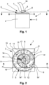
- Figure 1 shows a side view of a device 1 for small-volume bulk material.
- the small-volume bulk material is, for example, a medical product that can be in the form of a tablet, an oblong or a grain.
- the device 1 is used both for separating and for measuring bulk material.
- This device 1 comprises a lower section 2 and an upper section 3.
- the lower section 2 is surrounded by a housing 4.
- In the upper section 3 there is an arrangement for separating 3, whereby the upper section corresponds to the arrangement for separating.
- This arrangement for separating 3 comprises a plate element 5 designed as a vibration plate and an easily removable storage container 6 in which bulk material is stored.
- the storage container 6 can either be firmly connected to the plate element 5 or decoupled from this plate element 5. If the storage container 6 is decoupled from the plate element 5, the storage container 6 can be connected to the housing 4, for example.
- the storage container 6 comprises a small, lower opening 7 in a lower area, through which the bulk material can reach the plate element 5.
- Bulk material is in the Figure 1 not shown. Bulk material can be introduced into the storage container 6 via an upper feed opening (not visible in this view), which is located in an upper area of the storage container 6. For this purpose, bulk material feeders can be attached to the upper area of the storage container 6.
- the storage container 6 has a standard connection 8 in the upper area.
- This standard connection can, for example, be a clamp with which the corresponding bulk material feeder can be attached to the storage container 6.
- a conversion and thus an adaptation of the arrangement for separating to different bulk material feeds is therefore not necessary.
- the device can be used at different locations, i.e. also at locations where there is no space for a conversion or adaptation of the arrangement for separating or where tools for conversion or adaptation are not available.
- the bulk material feed 39 shown is a hose 39 through which bulk material can be introduced into the storage container 6. Since the storage container 6 has a standard connection 8, another bulk material feed, for example a funnel, can also be attached to the storage container 6 quickly and easily.
- the storage container 6 Since the storage container 6 is easy to remove, the storage container 6 can also be filled separately and then placed back on the device 1.
- Figure 2 is a top view of the Figure 1 The device 1 shown is shown in section through a plane S.
- the plate element 5 of the upper section 3 is arranged on the lower section 2 of the device 1.
- the lower opening 7 of the storage container 6 can also be seen through the section, through which the bulk material can reach the plate element 5.
- the bulk material which is in Figure 2 in the form of oblongs, is only partially provided with the reference number 9 for the sake of clarity.
- This bulk material 9 is introduced via a feed opening 10 which is arranged in the upper area of the storage container 6.
- a vibration drive for example a throw conveyor
- the bulk material 9 is moved along a path 14 in the direction of the arrow 11 until it finally reaches an opening 12 and falls downwards.
- the separated bulk material falls into a chamber of a transport device, for example into a chamber of a transport star.
- the transport device with the chambers is located in the lower section 2 and is therefore in Figure 2 not visible.
- the vibration drive is located in the lower section 2, it is in Figure 2 also not visible.
- the track 14 on which the bulk material 9 is transported is preferably divided into several track sections, whereby the track 14 is sufficiently long, so that the bulk material 9 can be separated on the way to the opening 12.
- the track 14 of the plate element 5 is constructed in a spiral shape and has three track sections, namely an inner track section 14', a middle track section 14" and an adjoining outer track section 14"'.
- the boundaries of the individual track sections 14', 14", 14′′′ are marked by dashed lines 16, 17.
- the track 14 is surrounded by an outer wall 15 which prevents the bulk material 9 from falling off the plate element 5. It is understood that the track 14 does not have to be constructed in a spiral shape, but can also have a different structure.
- Figure 3 shows a longitudinal section along AA through the Figure 2 shown device 1, whereby the upper section 3 is again arranged above the lower section 2.
- the upper section 3 is the arrangement for separation 3 and consists of the plate element 5 and the storage container 6, which can either be connected to the plate element 5 or decoupled from it.
- the standard connection 8 can also be seen.
- a bulk material feed is in Figure 3 not shown. Nor was it decided to Figure 3 Bulk material that is transported on the track 14 of the plate element 5 in the direction of the opening 12.
- the size of the lower opening 7 of the storage container 6 can be adjusted, whereby the amount of bulk material dispensed per unit of time can be changed or adapted to the size of the bulk material.
- vibration drive 18 In the lower section 2, directly below the plate element 5, there is the only schematically shown vibration drive 18, which is used not only to transport the bulk material in the direction of the opening 12, but also to separate it on the way there.
- the vibration drive 18 can be a throw conveyor that transports the bulk material and separates it from one another by means of vibration. Vibration drives for transporting bulk material by means of vibration are known, which is why a detailed description of the vibration drive 18 is omitted at this point.
- the vibration drive 18 is laterally surrounded by the transport device 19, wherein the transport device 19 is preferably designed in the shape of a wheel and in particular as a transport star (as in Figure 3 shown) or also designed as a transport rake.
- the transport device 19, designed as a transport star 19, is arranged above a floor 20 and comprises several chambers in which a previously separated bulk material is transported. In the Figure 3 only two chambers 21, 22 are visible.
- a measuring device 23 is provided beneath the base 20, which comprises at least one measuring station, the measuring device 23 being shown only partially and schematically. However, the measuring device 23 preferably comprises several measuring stations so that as many parameters of the bulk material as possible can be measured.
- the chamber 21 of the transport device 19 is located directly below the opening 12 of the plate element 5. This allows a bulk material that falls through the opening 12 to pass directly into the chamber 21 of the transport device 19.
- the opening 12 is equipped with a detector, for example a sound detector, which can detect whether only one bulk material or several bulk materials have entered the chamber.
- the bulk material After the bulk material has fallen into the chamber 21 of the transport device 19 and the detector has determined that only one bulk material has actually entered the chamber 21, the bulk material is guided in a first direction around the vibration drive 18 and above the measuring device 23.
- the bulk material lying in the chamber 21 passes at least the first measuring station of the measuring device 23.
- This first measuring station is preferably a scale.
- the scale detects whether only one bulk material has actually entered chamber 21. If the scale detects that several bulk materials or even only a few fragments of a bulk material have reached the chamber 21, the chamber 21 is emptied. To do this, the transport device 19 is moved back in a second direction, ie in the direction opposite to the first direction. The chamber 21 is moved to a waste container (not visible) which is installed in the floor 20. As soon as the chamber 21 is above the waste container, fragments or the multiple bulk materials fall into this waste container and are thus disposed of.
- the detector and the scale ensure that only one bulk material is measured by the measuring device at a time.
- the measuring device 23 comprises additional measuring stations in addition to the scale, through which a wide variety of parameters can be determined.
- additional measuring stations can be video cameras and/or NIR sensors and/or even a fracture chamber. In this fracture chamber, the width and length of a bulk material can be measured in addition to the hardness.
- the chemical composition or quality of the bulk material is determined using the NIR sensors, whereby four or eight such sensors can be provided, for example.
- Video cameras are used to check whether only one bulk material has actually entered the transport device 19 via the opening 12, or to check whether the bulk material has the desired shape.
- FIG 3 a central axis M is shown running through the device 1, which runs through the center of the device 1.
- the storage container 6 and the vibration drive 18 are arranged on this central axis M.
- the central axis M therefore also runs centrally through the vibration drive 18 and the storage container 6. Therefore, the transport device 19 rotates not only around the vibration drive 18, but also around the central axis M.
- Figure 4 shows a plan view of the lower section 2 of the device 1 after a horizontal section along a plane BB (see Figure 1 ).
- the transport device 19 surrounds the vibration drive 18 from all sides and can to move this vibration drive 18 forward in the direction of arrow 40 or backward in the direction of arrow 41.
- the transport device 19 is in Figure 4 designed as a transport star and has several chambers 21, 22, 24 to 33 that can hold bulk material.
- One bulk material 34 to 38 designed as an oblong is already in each of the chambers 21, 22, 24, 25, 26.
- the other chambers 27 to 33 are empty.
- the bulk material 38 has already been introduced into the chamber 21 via the opening 12 of the plate element 5 from above (see also Figure 3 ).
- This chamber 21 and the bulk material 38 located therein are in a position P0 (starting position). Since the detector attached to the opening 12 (not visible) has determined that there is only one bulk material, the chamber 21 with the bulk material 38 located therein is moved further forward in the direction of the arrow 40 and thus in the direction of the position P10.
- the bulk material 38 first reaches the position P1.
- a first measuring station of the measuring device 23 in the form of a scale is located in the floor 20. The scale is used to determine whether there is actually only one bulk material in the chamber 21.
- the transport device 19 would move back in the direction of the arrow 41 until the chamber 21 reached the position Px.
- the device 19 is then moved forward again in the direction of the arrow 40 until the chamber 21 has reached the starting position P0 again. In this starting position P0, the chamber 21 is again filled with bulk material.
- the transport device 19 is moved further forward in the direction of the arrow 40.
- the bulk material 33 passes through positions P2 to P10 one after the other.
- a further measuring station of the measuring device 23 can be arranged in the floor 20 at each of the positions P2 to P9.
- NIR sensor in the floor 20 as a measuring station.
- Each NIR sensor thus forms a measuring station and is - like the scale at position P1 - part of the measuring device 23.
- the measuring device 23 therefore comprises eight NIR sensors.
- NIR sensors are only provided as measuring stations at positions P2 to P5 in the floor 20 and that the bulk material is measured using video cameras in positions P6 to P9.
- the video cameras are also arranged in the floor 20, with each video camera forming a measuring station.
- the measuring device 23 would also have nine measuring stations, namely a scale, four video cameras and four NIR sensors.
- the transport device 19 is moved further in the direction of the arrow 40 until the chamber 21 with the bulk material 38 located therein has reached the position P10.
- the base 20 preferably has an opening 43 through which the bulk material 38 can be removed, for example because the waste container is arranged below the opening 43.
- the bulk material 38 is fed via the opening 43 to another measuring station, such as a fracture chamber (not visible), which is also located in the lower section 2 of the device 1, but is arranged below the vibration drive 18 and the transport device 19.
- a fracture chamber (not visible)
- a width and a length measurement of the bulk material can also be carried out.
- the transport device 19 can also have more or fewer than just 12 chambers, which means that the transport device can also travel to more or fewer positions.
- a measuring station of a measuring device can be provided at each of the positions traveled to by the transport device, so that the bulk material can be measured in each of the positions.
Landscapes
- Engineering & Computer Science (AREA)
- Mechanical Engineering (AREA)
- Filling Or Emptying Of Bunkers, Hoppers, And Tanks (AREA)
- Feeding Of Articles To Conveyors (AREA)
Abstract
Description
- Die Erfindung betrifft eine Vorrichtung für kleinvolumiges Schüttgut nach den Merkmalen des Patentanspruchs 1.
- Damit kleinvolumiges Schüttgut hinsichtlich Qualität und Eigenschaften, wie zum Beispiel der Härte, vermessen werden kann, muss das Schüttgut zuvor vereinzelt werden. Dies geschieht mit einer Vorrichtung zur Vereinzelung von Schüttgut. Nachdem das Schüttgut vereinzelt wurde, kann es mittels Vermessungsstationen vermessen werden. Vorrichtungen, die sowohl eine Vorrichtung zur Vereinzelung als auch Vermessungsstationen umfassen, benötigen viel Stellplatz, weil sie sehr ausladend aufgebaut sind.
-
DE 10 2017 114 972 A1 betrifft ein Verfahren zum Versorgen einer Nietmaschiene mit Nietelementen, insbesondere während des Betriebs der Nietmaschine, wobei mindestens eine Nietelementbereitstellungsanordnung mit mindestens einer Nietelementbereitstellungseinheit zur Bereitstellung und zur Vereinzelung der Nietelemente vorgesehen ist, wobei die Nietmaschine eine Nietelementaufnahmeanordnung mit mindestens einer Nietelementaufnahme zur Aufnahme der Nietelemente aufweist, wobei zumindest ein Teil des Transports von einer der Nietelmentbereitstellungseinheiten zu einer der Nietelementaufnahmen roboterbasiert erfolgt. - Weiterhin ist aus
AT 412 398 B - Ferner beschreibt
US 2017/0137227 A1 eine Transportvorrichtung, die ein endloses Vakuumförderband mit mehreren Perforationen aufweist. Das Förderband transportiert Partikel entlang einer Transportrichtung, während sie zu den Perforationen angesaugt werden, wodurch eine sich bewegende Transportoberfläche definiert wird. Die Transportfläche erstreckt sich in einer im Wesentlichen vertikalen Ebene und die Transportrichtung ist relativ zur horizontalen Richtung nach oben geneigt. Eine geneigte Recyclingschale befördert vom Förderband gefallene Partikel durch Schwerkraft zurück zu einer Aufgabenzone. Eine Trennwand trennt eine Verarbeitungszone von einer Reinzone der Vorrichtung. Das Transportband wirkt mit einem länglichen Vakuumkasten zusammen, der an einer Seite offen ist, wobei die offene Seite durch einen länglichen Schieber abgedeckt ist. Der Schieber hat Saugöffnungen mit einem entlang der Transportrichtung variierenden Querschnitt. - Zudem ist aus
US 2005/0062466 A1 eine Transportvorrichtung für elektronische Teile bekannt, die ein Transportmedium mit mehreren Reihen von Holräumen enthält. Die Linien sind bezüglich der Rotationsachse konzentrisch. Eine Antriebsvorrichtung treibt das Transportmedium rotierend an. Eine Zuführvorrichtung führt separat eine Vielzahl von zufällig eingeführten elektronischen Bauteilen nacheinander zu. Eine Zuführeinrichtung führt die von der Zuführeinrichtung separat zugeführten elektronischen Bauteile in die Kavitäten des Transportmediums ein. Eine Entnahmevorrichtung entnimmt die elektronischen Bauteile aus den Hohlräumen des Transportmediums. - Ferner beschreibt
WO 98/19945 A2 - Des Weiteren beschreibt
EP 2 664 551 A1 ein Verfahren, dass das Bereitstellen einer Zuführvorrichtung zum Aufnehmen und Weitergeben kleiner pharmazeutischer Produkte umfasst, wobei die pharmazeutischen Produkte von einem Schwingförderer transportiert werden. Eine Produktmenge wird auf einem Anfangsbereich des Förderers in einem Bereich nach einem Dosierelement durch einen Eingabesensor gemessen. Die durch die Abgabevorrichtung geführten Produkte werden von einem Zählsensor gezählt, z.B. Lichtgittersensor. Der durch die Betriebsparameter des Dosierorgans und des Förderers ermittelte Wert wird automatisch durch eine Regeleinrichtung aufgrund der Sensoren eingestellt. - Schließlich ist aus
US 2016/0167866 A1 eine kleine Medikamentenzuführung bekannt, die einen Behälter umfasst, der die Breite oder Höhe von Medikamenten einschränken kann, so dass die Zuführung eine breite Palette von Medikamenten mit verschiedenen unterschiedlichen Formen oder Größen handhaben und leicht angepasst werden kann. Ein Breitenbegrenzungselement, das die Breite eines Zwischenraums über einem Umfangabschnitt vergrößert oder verkleinert, ist so angeordnet, dass es einem Abgabemechanismus gegenüberliegt, der Arzneimittel mit einer höheren Geschwindigkeit als der des Umfangsabschnitts zur Außenseite eines Behälters abgibt. Ein Abstand zwischen dem Breitenbegrenzungselement und dem Abgabemechanismus wird in Übereinstimmung mit einer Breite eines in einer Messkammer gehaltenen Messobjekts geändert. Die Höhe der auf dem peripheren Abschnitt platzierten Arzneimittel wird durch ein Höhebegrenzungselement gemäß der Höhe des Messziels begrenzt. - Aufgabe der vorliegenden Erfindung ist es deshalb, eine Vorrichtung für kleinvolumiges Schüttgut bereitzustellen, die sehr kompakt aufgebaut ist und mit der Schüttgut exakt vermessen werden kann.
- Diese Aufgabe wird durch eine Vorrichtung nach den Merkmalen des Patentanspruchs 1 gelöst.
- Die Erfindung betrifft somit eine Vorrichtung für kleinvolumiges Schüttgut umfassend eine Anordnung zur Vereinzelung, mit der das Schüttgut vereinzelbar ist, sowie eine unterhalb der Anordnung zur Vereinzelung angeordnete Messvorrichtung. Die Messvorrichtung weist zumindest eine Messstation auf, mit der ein Schüttgut vermessen werden kann. Bei dem kleinvolumigen Schüttgut handelt es sich beispielsweise um ein medizinisches Produkt, wie zum Beispiel eine Tablette. Der Begriff Schüttgut wird im Folgenden für ein einzelnes Produkt und an manchen Passagen auch als Sammelbegriff für mehrere dieser Produkte (Schüttgüter) verwendet.
- Zwischen der Anordnung zur Vereinzelung und der Messvorrichtung ist eine Transportvorrichtung vorgesehen, mit der das Schüttgut zu der zumindest eine Messstation der Messvorrichtung transportiert werden kann.
- Vorteilhaft bei dieser Vorrichtung ist, dass diese sehr kompakt aufgebaut ist und dass ein Schüttgut durch mehrere Messtationen transportiert wird, in denen es vermessen wird.
- Vorteilhaft ist zudem, dass die Anordnung zur Vereinzelung einen Vorratsbehälter sowie ein als Vibrationsplatte ausgebildetes Plattenelement umfasst, wobei der Vorratsbehälter oberhalb der Vibrationsplatte angeordnet ist. Dadurch wird gewährleistet, dass das Schüttgut ausschließlich durch Gravitation auf die Vibrationsplatte gelangt und kein zusätzlicher Antrieb erforderlich ist, mit dem das Schüttgut auf die Vibrationsplatte transportiert werden muss. Da auf einen zusätzlichen Antrieb verzichtet werden kann, trägt diese Bauweise dazu bei, dass die Vorrichtung kompakt aufgebaut ist. Vorteilhaft ist zudem, dass die Vibrationsplatte sehr einfach zu reinigen ist.
- Die Vorrichtung umfasst einen Vibrationsantrieb, der unterhalb der Vibrationsplatte angeordnet ist und mit dem die Vibrationsplatte in Vibration versetzt werden kann, um das aus dem Vorratsbehälter kommende Schüttgut zu vereinzeln und zur Transportvorrichtung zu transportieren. Der Umstand, dass der Vibrationsantrieb direkt unterhalb der Vibrationsplatte angeordnet ist, trägt dazu bei, dass die Vorrichtung kompakt aufgebaut ist.
- Besonders vorteilhaft ist, dass der Vibrationsantrieb sowie die Transportvorrichtung auf einer Ebene angeordnet sind, weil dadurch viel Platz gespart werden kann. Auch dies trägt zu dem kompakten Aufbau der Vorrichtung bei.
- Bevorzugt handelt es sich bei der Transportvorrichtung um einen Transportstern oder einen Transportrechen, weil dann der Vibrationsantrieb von der Transportvorrichtung seitlich umgeben ist. Die Transportvorrichtung dreht sich somit um den Vibrationsantrieb. Diese Bauweise ist platzsparend und trägt zusätzlich zur Kompaktheit der Vorrichtung bei.
- Vorteilhaft ist auch, dass der Vorratsbehälter an einer Zuführungsöffnung, über die Schüttgut in den Vorratsbehälter eingebracht werden kann, einen Normanschluss besitzt, an dem Schüttgutzuführungen verschiedenen Typs schnell und einfach angebracht und wieder entfernt werden können. Diese Zuführungsöffnung sowie der Normanschluss können in einem oberen Abschnitt des Vorratsbehälters oder auch an einer Seite des Vorratsbehälter vorgesehen sein. Ein Umbau und damit eine Anpassung der Anordnung zur Vereinzelung an Schüttgutzuführung unterschiedlichen Typs ist daher nicht erforderlich. Dadurch kann die Vorrichtung an verschiedenen Standorten eingesetzt werden, also auch an Standorten, an denen Platz für einen Umbau bzw. Anpassung der Anordnung zur Vereinzelung nicht vorhanden ist oder aber Werkzeug zum Umbau bzw. Anpassung nicht verfügbar ist.
- Es wird hiermit auch explizit vorgeschlagen, mehrere Merkmale der einzelnen beschriebenen Ausführungsformen untereinander zu kombinieren.
- Die Vorrichtung wird im Folgenden anhand von Figuren näher erläutert. Es zeigen:
- Figur 1
- eine Seitenansicht einer Vorrichtung für kleinvolumiges Schüttgut;
- Figur 2
- eine Draufsicht auf die in
Figur 1 gezeigte Vorrichtung nach Schnitt durch eine Ebene S; - Figur 3
- einen Längsschnitt entlang A-A durch die in
Figur 2 gezeigte Vorrichtung und - Figur 4
- eine Draufsicht auf die Vorrichtung nach Schnitt durch die Ebene B-B bei der in
Figur 1 gezeigten Vorrichtung. -
Figur 1 zeigt eine Seitenansicht einer Vorrichtung 1 für kleinvolumiges Schüttgut. Bei dem kleinvolumigen Schüttgut handelt es sich beispielsweise um ein medizinisches Produkt, das in Form einer Tablette, eines Oblongs oder eines Korns vorliegen kann. Die Vorrichtung 1 dient sowohl zum Vereinzeln als auch zum Vermessen von Schüttgut. Diese Vorrichtung 1 umfasst einen unteren Abschnitt 2 sowie einen oberen Abschnitt 3. Der untere Abschnitt 2 ist von einem Gehäuse 4 umgeben. In dem oberen Abschnitt 3 befindet sich eine Anordnung zur Vereinzelung 3, womit der obere Abschnitt der Anordung zur Vereinzelung entspricht. Diese Anordnung zur Vereinzelung 3 umfasst ein als Vibrationsplatte ausgebildetes Plattenelement 5 sowie einen einfach abzunehmenden Vorratsbehälter 6, in dem Schüttgut bevorratet werden kann. Der Vorratsbehälter 6 kann mit dem Plattenelement 5 entweder fest verbunden sein, oder von diesem Plattenelement 5 entkoppelt sein. Ist der Vorratsbehälter 6 von dem Plattenelement 5 entkoppelt, so kann der Vorratsbehälter 6 beispielsweise mit dem Gehäuse 4 verbunden sein. - Der Vorratsbehälter 6 umfasst in einem unteren Bereich eine kleine, untere, Öffnung 7, über die das Schüttgut auf das Plattenelement 5 gelangen kann. Schüttgut ist in der
Figur 1 nicht dargestellt. Über eine obere Zuführungsöffnung (in dieser Ansicht nicht zu sehen), die sich in einem oberen Bereich des Vorratsbehälters 6 befindet, kann Schüttgut in den Vorratsbehälter 6 eingebracht werden. Dazu können Schüttgutzuführungen an den oberen Bereich des Vorratsbehälter 6 angebracht werden. - Damit Schüttgutzuführungen verschiedenen Typs schnell und einfach am Vorratsbehälter 6 angebracht werden können, besitzt der Vorratsbehälter 6 im oberen Bereich einen Normanschluss 8. Dieser Normanschluss kann beispielsweise eine Schelle sein, mit der die entsprechende Schüttgutzuführung an dem Vorratsbehälter 6 befestigt werden kann.
- Ein Umbau und damit eine Anpassung der Anordnung zur Vereinzelung an unterschiedliche Schüttgutzuführungen ist daher nicht erforderlich. Dadurch kann die Vorrichtung an verschiedenen Standorten eingesetzt werden, also auch an Standorten, an denen Platz für einen Umbau bzw. Anpassung der Anordnung zur Vereinzelung nicht vorhanden ist oder aber Werkzeug zum Umbau bzw. Anpassung nicht verfügbar ist.
- Bei der in
Figur 1 dargestellten Schüttgutzuführung 39 handelt es sich um einen Schlauch 39, über den Schüttgut in den Vorratsbehälter 6 eingebracht werden kann. Da der Vorratsbehälter 6 einen Normanschluss 8 besitzt, kann auch eine andere Schüttgutzuführung, zum Beispiel ein Trichter, einfach und schnell an dem Vorratsbehälter 6 angebracht werden. - Da der Vorratsbehälter 6 einfach abzunehmen ist, kann der Vorratsbehälter 6 auch separat befüllt werden und anschließend wieder auf die Vorrichtung 1 gesetzt werden.
- In
Figur 2 ist eine Draufsicht auf die inFigur 1 gezeigte Vorrichtung 1 nach Schnitt durch eine Ebene S dargestellt. - Auf dem unteren Abschnitt 2 der Vorrichtung 1 ist das Plattenelement 5 des oberen Abschnitts 3 angeordnet. Durch den Schnitt ist auch die untere Öffnung 7 des Vorratsbehälters 6 zu sehen, über die das Schüttgut auf das Plattenelement 5 gelangen kann. Das Schüttgut, das in
Figur 2 in Form von Oblongs vorliegt, ist der Übersicht halber nur teilweise mit dem Bezugszeichen 9 versehen. Dieses Schüttgut 9 wird über eine Zuführungsöffnung 10 eingebracht, die im oberen Bereich des Vorratsbehälters 6 angebracht ist. Möglich ist aber auch, die Zuführungsöffnung 10 beispielsweise an der, der Öffnung 7 gegenüberliegenden Seite, und nicht im oberen Bereich der Vorratsbehälters 6 vorzusehen. - Durch einen Vibrationsantrieb, beispielsweise einen Wurfförderer, wird das Schüttgut 9 entlang einer Bahn 14 in Richtung des Pfeils 11 bewegt, bis es schließlich eine Öffnung 12 erreicht und nach unten fällt. Dort fällt das vereinzelte Schüttgut in eine Kammer einer Transportvorrichtung, zum Beispiel in eine Kammer eines Transportsterns. Die Transportvorrichtung mit den Kammern befindet sich im unteren Abschnitt 2 und ist deshalb in
Figur 2 nicht zu sehen. Bei dem Transport des Schüttguts in Richtung des Pfeils 11, d.h. in Richtung der Öffnung 12, wird das Schüttgut 9 durch den Vibrationsantrieb zudem vereinzelt. Weil sich der Vibrationsantrieb im unteren Abschnitt 2 befindet, ist dieser inFigur 2 ebenfalls nicht zu sehen. - Bei dem Transport des Schüttguts 9 in Richtung der Öffnung 12 wird das Schüttgut über ein Sieb 13 geführt. Durch dieses Sieb 13 fällt Staub oder kleinere Bruchstücke des Schüttguts 9 nach unten in einen unter dem Sieb 13 angeordneten Behälter (nicht zu sehen) und wird so von dem Plattenelement 5 entfernt. So wird verhindert, dass Staub oder kleinere Bruchstücke in die Öffnung 12 gelangen und so Ergebnisse der Messungen des zu vermessenden Schüttguts verfälschen.
- Die Bahn 14, auf der das Schüttgut 9 transportiert wird, ist vorzugsweise in mehrere Bahnabschnitte unterteilt, wodurch die Strecke der Bahn 14 ausreichend lang ist, damit das Schüttgut 9 auf dem Weg zur Öffnung 12 vereinzelt werden kann. Die Bahn 14 des Plattenelements 5 ist spiralförmig aufgebaut und weist drei Bahnabschnitte auf, nämlich einen inneren Bahnabschnitt 14', einen mittleren Bahnabschnitt 14" sowie einen, sich daran anschließenden, äußeren Bahnabschnitt 14"' auf. Die Grenzen der einzelnen Bahnabschnitte 14', 14", 14‴ sind durch gestrichelte Linien 16, 17 gekennzeichnet. Außen wird die Bahn 14 von einer Außenwand 15 umgeben, die verhindert, dass das Schüttgut 9 von dem Plattenelement 5 fällt. Es versteht sich, dass die Bahn 14 nicht spiralförmig aufgebaut sein muss, sondern auch einen anderen Aufbau besitzen kann.
-
Figur 3 zeigt einen Längsschnitt entlang A-A durch die inFigur 2 gezeigte Vorrichtung 1, wobei der obere Abschnitt 3 wiederum oberhalb des unteren Abschnitts 2 angeordnet ist. Der obere Abschnitt 3 ist die Anordnung zur Vereinzelung 3 und besteht aus dem Plattenelement 5 sowie dem Vorratsbehälters 6, der entweder mit dem Plattenelement 5 verbunden oder von diesem entkoppelt angeordnet sein kann. Neben der unteren Öffnung 7 zum Ausbringen des Schüttguts auf das Plattenelement 5 ist noch der Normanschluss 8 zu erkennen. Eine Schüttgutzuführung ist inFigur 3 nicht dargestellt. Auch wurde darauf verzichtet, inFigur 3 Schüttgut darzustellen, das auf der Bahn 14 des Plattenelements 5 in Richtung der Öffnung 12 transportiert wird. - Vorzugsweise kann die Größe der unteren Öffnung 7 des Vorratsbehälters 6 verstellt werden, wodurch die ausgebrachte Menge an Schüttgut pro Zeiteinheit verändert oder der Größe des Schüttguts angepasst werden kann.
- Im unteren Abschnitt 2 befindet sich direkt unterhalb des Plattenelements 5 der nur schematisch dargestellte Vibrationsantrieb 18, mit dem das Schüttgut nicht nur in Richtung der Öffnung 12 transportiert wird, sondern auch auf dem Weg dahin vereinzelt wird. Bei dem Vibrationsantrieb 18 kann es sich um einen Wurfförderer handeln, der durch Vibration das Schüttgut transportiert und voneinander separiert. Vibrationsantriebe für den Transport von Schüttgut mittels Vibration sind bekannt, weshalb auf eine detaillierte Beschreibung des Vibrationsantrieb 18 an dieser Stelle verzichtet wird.
- Der Vibrationsantrieb 18 wird seitlich von der Transportvorrichtung 19 umgeben, wobei die Transportvorrichtung 19 vorzugsweise radförmig ausgebildet ist und insbesondere als Transportstern (wie in
Figur 3 dargestellt) oder auch als Transportrechen ausgestaltet ist. - Die als Transportstern 19 ausgebildete Transportvorrichtung 19 ist oberhalb eines Bodens 20 angeordnet und umfasst mehrere Kammern, in denen ein vorher vereinzeltes Schüttgut transportiert wird. In der
Figur 3 sind nur zwei Kammern 21, 22 zu sehen. - Unterhalb des Bodens 20 ist eine Messvorrichtung 23 vorgesehen, die zumindest eine Messstation umfasst, wobei die Messvorrichtung 23 nur ausschnittsweise und schematisch dargestellt ist. Vorzugsweise umfasst die Messvorrichtung 23 jedoch mehrere Messstationen, damit möglichst viele Parameter des Schüttguts vermessen werden können.
- Wie in
Figur 3 zu sehen, befindet sich die Kammer 21 der Transportvorrichtung 19 direkt unterhalb der Öffnung 12 des Plattenelements 5. Dadurch kann ein Schüttgut, das durch die Öffnung 12 fällt, direkt in die Kammer 21 der Transportvorrichtung 19 gelangen. Die Öffnung 12 ist mit einem Detektor ausgestattet, zum Beispiel einem Schalldetektor, mit dem detektiert werden kann, ob nur ein Schüttgut oder mehrere Schüttgüter in die Kammer gelangt sind. - Nachdem das Schüttgut in die Kammer 21 der Transportvorrichtung 19 gefallen ist, und der Detektor festgestellt hat, dass tatsächlich nur ein Schüttgut in die Kammer 21 gelangt ist, wird das Schüttgut in eine erste Richtung um den Vibrationsantrieb 18 herum und oberhalb der Messvorrichtung 23 geführt. Dabei passiert das in der Kammer 21 liegende Schüttgut die zumindest erste Messstation der Messvorrichtung 23. Bei dieser ersten Messstation handelt es sich vorzugsweise um eine Waage.
- Mit der Waage wird detektiert, ob tatsächlich nur ein Schüttgut in die Kammer 21 gelangt ist. Wird über die Waage festgestellt, dass mehrere Schüttgüter oder gar nur wenige Bruchstücke eines Schüttguts in die Kammer 21 gelangt sind, wird die Kammer 21 entleert. Dazu wird die Transportvorrichtung 19 zurück in eine zweite Richtung, d.h. in die der ersten Richtung entgegengesetzten Richtung, bewegt. Dabei wird die Kammer 21 zu einem Abfallbehälters (nicht zu sehen) bewegt, der im Boden 20 eingebracht ist. Sobald sich die Kammer 21 oberhalb des Abfallbehälters befindet, fallen Bruchstücke bzw. die mehreren Schüttgüter in diesen Abfallbehälter und werden so entsorgt.
- Durch den Detektor sowie durch die Waage wird gewährleistet, dass immer nur ein Schüttgut durch die Messvorrichtung vermessen wird.
- Vorzugsweise umfasst die Messvorrichtung 23 neben der Waage noch weitere Messstationen, wodurch die unterschiedlichsten Parameter ermittelt werden können. So können diese weiteren Messstationen Videokameras und/oder NIR-Sensoren und/oder gar eine Bruchkammer sein. In dieser Bruchkammer können neben der Härte auch die Breite und die Länge eines Schüttguts vermessen werden. Mit den NIR-Sensoren, wobei beispielsweise vier oder acht solche Sensoren vorgesehen sein können, wird die chemische Zusammensetzung bzw. die Qualität des Schüttguts ermittelt. Videokameras dienen dazu zu überprüfen, ob tatsächlich nur ein Schüttgut über die Öffnung 12 in die Transportvorrichtung 19 gelangt ist, oder auch dazu zu prüfen, ob das Schüttgut die gewünschte Form hat.
- In
Figur 3 ist eine durch die Vorrichtung 1 verlaufende Mittelachse M gezeigt, die durch das Zentrum der Vorrichtung 1 verläuft. Auf dieser Mittelachse M sind der Vorratsbehälter 6 sowie der Vibrationsantrieb 18 angeordnet. Die Mittelachse M verläuft damit auch mittig durch den Vibrationsantrieb 18 sowie den Vorratsbehälter 6. Deshalb dreht sich die Transportvorrichtung 19 nicht nur um den Vibrationsantrieb 18, sondern auch um die Mittelachse M. -
Figur 4 zeigt eine Draufsicht auf den unteren Abschnitt 2 der Vorrichtung 1 nach einem Horizontalschnitt entlang einer Ebene B-B (sieheFigur 1 ). Die Transportvorrichtung 19 umgibt den Vibrationsantrieb 18 von allen Seiten und kann um diesen Vibrationsantrieb 18 in Richtung des Pfeils 40 vorbewegt bzw. in Richtung des Pfeils 41 zurückbewegt werden. - Die Transportvorrichtung 19 ist in
Figur 4 als Transportstern ausgebildet und weist mehrere Kammern 21, 22, 24 bis 33 auf, die Schüttgut aufnehmen können. Jeweils ein als Oblong ausgebildetes Schüttgut 34 bis 38 befindet sich bereits in den Kammern 21, 22, 24, 25, 26. Die anderen Kammern 27 bis 33 sind leer. - In die Kammer 21 wurde das Schüttgut 38 über die Öffnung 12 des Plattenelements 5 von oben bereits eingebracht (siehe auch
Figur 3 ). Diese Kammer 21 und das darin befindliche Schüttgut 38 befindet sich in einer Position P0 (Ausgangsposition). Da der an der Öffnung 12 angebrachte Detektor (nicht zu sehen) festgestellt hat, dass es sich nur um ein Schüttgut handelt, wird die Kammer 21 mit dem darin befindlichen Schüttgut 38 weiter vor in Richtung des Pfeils 40 und damit in Richtung der Position P10 bewegt. Dabei gelangt das Schüttgut 38 zuerst zu der Position P1. In dieser Position P1 befindet sich im Boden 20 eine erste Messstation der Messvorrichtung 23 in Form einer Waage. Mit der Waage wird ermittelt, ob es sich tatsächlich nur um ein Schüttgut handelt, das sich in der Kammer 21 befindet. Würden sich in der Kammer 21 nur ein paar Bruchstücke oder gar zwei Schüttgüter befinden, so würde die Transportvorrichtung 19 in Richtung des Pfeils 41 zurückfahren, bis die Kammer 21 die Position Px erreicht hat. Dort befindet sich im Boden 20 eine Öffnung 42, unter der ein Abfallbehälter (nicht zu sehen) angeordnet ist, so dass das in der Kammer 21 befindliche Schüttgut oder Bruchstücke in den Abfallbehälter fallen und somit entsorgt werden. Sodann wird die Vorrichtung 19 wieder vor in Richtung des Pfeils 40 gefahren, bis die Kammer 21 wieder die Ausgangsposition P0 erreicht hat. In dieser Ausgangsposition P0 wird die Kammer 21 erneut mit einem Schüttgut bestückt. - Durch Entsorgung von Bruchstücken wird verhindert, dass Bruchstücke weiter vorwärts in Richtung der Position P10 transportiert werden und so auf den folgenden Messstationen liegen bleiben und diesen Stationen damit verdrecken.
- Es versteht sich damit, dass es somit auch möglich ist, dass die Transportvorrichtung 19 weiter vorwärts in Richtung der Position P10 bewegt wird und dass auf eine Entsorgung von Bruchstücken auch verzichtet werden kann.
- Da sich in der Kammer 21 jedoch nur ein Schüttgut 38 befindet, wird die Transportvorrichtung 19 weiter vor in Richtung des Pfeils 40 bewegt. Dabei passiert das Schüttgut 33 nacheinander die Positionen P2 bis P10. Dabei kann im Boden 20 bei jeder der Positionen P2 bis P9 eine weitere Messstation der Messvorrichtung 23 angeordnet sein. So ist es beispielsweise möglich, in dem Boden 20 als Messstationen jeweils einen NIR-Sensor vorzusehen. Jeder NIR-Sensor bildet somit eine Messstation und ist - wie auch die Waage bei der Position P1 - Teil der Messvorrichtung 23. Beim Passieren dieser Positionen P2 bis P9 wird das Schüttgut 38 somit mittels NIR vermessen. Die Messvorrichtung 23 umfasst damit acht NIR-Sensoren. Denkbar ist natürlich auch, dass nur bei den Positionen P2 bis P5 im Boden 20 NIR-Sensoren als Messstationen vorgesehen sind und dass in den Positionen P6 bis P9 das Schüttgut mittels Videokameras vermessen wird. Dazu sind die Videokameras ebenfalls im Boden 20 angeordnet, wobei jede Videokamera eine Messstation bildet. In diesem Fall würde die Messvorrichtung 23 also ebenfalls neun Messstationen aufweisen, nämlich eine Waage, vier Videokameras sowie vier NIR-Sensoren.
- Nachdem die Kammer 21 mit dem Schüttgut 38 die Position P9 passiert hat, wird die Transportvorrichtung 19 weiter in Richtung des Pfeils 40 bewegt, bis die Kammer 21 mit dem darin befindlichen Schüttgut 38 die Position P10 erreicht hat. In der Position P10 weist der Boden 20 vorzugsweise eine Öffnung 43 auf, durch die das Schüttgut 38 entfernt werden kann, zum Beispiel weil unterhalb der Öffnung 43 der Abfallbehälter angeordnet ist.
- Es ist jedoch auch denkbar, dass das Schüttgut 38 über die Öffnung 43 einer weiteren Messstation, wie zum Beispiel einer Bruchkammer (nicht zu sehen) zugeführt wird, die sich zwar ebenfalls im unteren Abschnitt 2 der Vorrichtung 1 befindet, jedoch unterhalb des Vibrationsantriebs 18 sowie der Transportvorrichtung 19 angeordnet ist. In dieser Bruchkammer kann neben einer Härtemessung auch eine Breiten- sowie eine Längenmessung des Schüttguts durchgeführt werden.
- Es versteht sich, dass die Transportvorrichtung 19 auch mehr oder weniger als nur 12 Kammern aufweisen kann, womit die Transportvorrichtung auch mehr oder weniger Positionen anfahren kann. Bei jeder der von der Transportvorrichtung angefahrenen Position kann dabei jeweils eine Messstation einer Messvorrichtung vorgesehen sein, so dass das Schüttgut in jeder der Positionen vermessen werden kann.
-
- 1
- Seitenansicht einer Vorrichtung
- 2
- Unterer Abschnitt
- 3
- Vereinzelung
- 4
- Gehäuse
- 5
- Plattenelement
- 6
- Vorratsbehälter
- 7
- Öffnung
- 8
- Normanschluss
- 9
- Schüttgut
- 10
- Zuführungsöffnung
- 11
- Pfeil
- 12
- Öffnung
- 13
- Sieb
- 14
- Bahn
- 15
- Außenwand
- 16, 17
- Gestrichelte Linien
- 18
- Vibrationsantrieb
- 19
- Transportvorrichtung
- 20
- Boden
- 21,22
- Kammern
- 23
- Messvorrichtung
- 24 bis 33
- Kammern
- 34 bis 38
- Schüttgut
- 39
- Schüttgutzuführung
- 40, 41
- Pfeil
- 42
- ---
- 43
- Öffnung
- M
- Mittelachse
Claims (6)
- Vorrichtung (1) für kleinvolumiges Schüttgut umfassend- eine Anordnung zur Vereinzelung (3), mit der das Schüttgut vereinzelbar ist,- eine unterhalb der Anordnung zur Vereinzelung (3) angeordnete Messvorrichtung (23), wobei die Messvorrichtung (23) mehrere Messstationen umfasst, mit der ein Schüttgut vermessen werden kann, wobei die Messstationen in einem Boden (20) der Vorrichtung (1) angeordnet sind, wobei eine erste der mehreren Messstationen eine Waage ist und wobei zumindest eine der weiteren Messstationen ein NIR-Sensor oder eine Videokamera ist und wobei- zwischen der Anordnung zur Vereinzelung (3) und der Messvorrichtung (23) eine Transportvorrichtung (19) angeordnet ist, mit der das Schüttgut den Messstationen der Messvorrichtung (23) zuführbar ist.
- Vorrichtung nach Patentanspruch 1, dadurch gekennzeichnet, dass die Anordnung zur Vereinzelung (3) einen Vorratsbehälter (6) sowie eine Vibrationsplatte (5) umfasst, wobei der Vorratsbehälter (6) oberhalb der Vibrationsplatte (5) angeordnet ist.
- Vorrichtung nach Patentanspruch 2, dadurch gekennzeichnet, dass ein Vibrationsantrieb (18) vorgesehen ist, der unterhalb der Vibrationsplatte (5) angeordnet ist und mit dem die Vibrationsplatte (5) in Vibration versetzt werden kann, um das aus dem Vorratsbehälter (6) kommende Schüttgut zu vereinzeln.
- Vorrichtung nach Patentanspruch 3, dadurch gekennzeichnet, dass der Vibrationsantrieb (18) sowie die Transportvorrichtung (19) auf einer Ebene angeordnet sind.
- Vorrichtung nach Patentanspruch 4, dadurch gekennzeichnet, dass der Vibrationsantrieb (18) von der Transportvorrichtung (19) seitlich umgeben ist.
- Vorrichtung nach Patentanspruch 2, dadurch gekennzeichnet, dass der Vorratsbehälter (6) einen Normanschluss (8) besitzt, an dem Schüttgutzuführungen (9) verschiedenen Typs anbringbar sind.
Applications Claiming Priority (3)
| Application Number | Priority Date | Filing Date | Title |
|---|---|---|---|
| DE102022100828.2A DE102022100828B4 (de) | 2022-01-14 | 2022-01-14 | Vorrichtung für kleinvolumiges Schüttgut |
| EP23701247.1A EP4463406A1 (de) | 2022-01-14 | 2023-01-12 | Vorrichtung zum vereinzeln und messen eines kleinvolumigen schüttguts |
| PCT/EP2023/050655 WO2023135219A1 (de) | 2022-01-14 | 2023-01-12 | Vorrichtung zum vereinzeln und messen eines kleinvolumigen schüttguts |
Related Parent Applications (2)
| Application Number | Title | Priority Date | Filing Date |
|---|---|---|---|
| EP23701247.1A Division-Into EP4463406A1 (de) | 2022-01-14 | 2023-01-12 | Vorrichtung zum vereinzeln und messen eines kleinvolumigen schüttguts |
| EP23701247.1A Division EP4463406A1 (de) | 2022-01-14 | 2023-01-12 | Vorrichtung zum vereinzeln und messen eines kleinvolumigen schüttguts |
Publications (2)
| Publication Number | Publication Date |
|---|---|
| EP4467964A2 true EP4467964A2 (de) | 2024-11-27 |
| EP4467964A3 EP4467964A3 (de) | 2024-12-25 |
Family
ID=85036552
Family Applications (2)
| Application Number | Title | Priority Date | Filing Date |
|---|---|---|---|
| EP24197161.3A Pending EP4467964A3 (de) | 2022-01-14 | 2023-01-12 | Vorrichtung für kleinvolumiges schüttgut |
| EP23701247.1A Pending EP4463406A1 (de) | 2022-01-14 | 2023-01-12 | Vorrichtung zum vereinzeln und messen eines kleinvolumigen schüttguts |
Family Applications After (1)
| Application Number | Title | Priority Date | Filing Date |
|---|---|---|---|
| EP23701247.1A Pending EP4463406A1 (de) | 2022-01-14 | 2023-01-12 | Vorrichtung zum vereinzeln und messen eines kleinvolumigen schüttguts |
Country Status (3)
| Country | Link |
|---|---|
| EP (2) | EP4467964A3 (de) |
| DE (1) | DE102022100828B4 (de) |
| WO (1) | WO2023135219A1 (de) |
Families Citing this family (2)
| Publication number | Priority date | Publication date | Assignee | Title |
|---|---|---|---|---|
| DE102024112966A1 (de) * | 2024-05-08 | 2025-11-13 | Thilo Kraemer | Vorrichtung für kleinvolumiges Schüttgut |
| DE102025117039A1 (de) | 2024-08-01 | 2026-02-05 | Thilo Kraemer | Testgerät zum Vermessen von kleinvolumigem Schüttgut |
Citations (6)
| Publication number | Priority date | Publication date | Assignee | Title |
|---|---|---|---|---|
| WO1998019945A2 (de) | 1996-11-08 | 1998-05-14 | Dr. Schleuniger Pharmatron Ag | Tablettenprüfgerät |
| US20050062466A1 (en) | 2000-07-11 | 2005-03-24 | Murata Manufacturing Co., Ltd. | Electronic part transport device and inspection apparatus using the same |
| EP2664551A1 (de) | 2012-05-16 | 2013-11-20 | UHLMANN PAC-SYSTEME GmbH & Co. KG | Verfahren zum optimierten Vereinzeln und Abgeben von kleinen pharmazeutischen Produkten |
| US20160167866A1 (en) | 2013-07-25 | 2016-06-16 | Tosho, Inc. | Drug feeder |
| US20170137227A1 (en) | 2014-06-30 | 2017-05-18 | Qualysense Ag | Transport apparatus with vacuum belt |
| DE102017114972A1 (de) | 2017-04-03 | 2018-10-04 | Broetje-Automation Gmbh | Verfahren zum Versorgen einer Nietmaschine mit Nietelementen |
Family Cites Families (5)
| Publication number | Priority date | Publication date | Assignee | Title |
|---|---|---|---|---|
| AT412398B (de) | 1990-01-18 | 2005-02-25 | Sticht Walter | Linearfördervorrichtung für einzelteile |
| EP1594612B1 (de) | 2003-02-12 | 2006-06-07 | Thilo Krämer | Vorrichtung zur qualitätskontrolle fester, pharmazeutischer erzeugnisse |
| ATE401271T1 (de) * | 2004-09-20 | 2008-08-15 | Thilo Kraemer | Fördervorrichtung für objekte von fester oder gelartiger konsistenz sowie verfahren zur förderung derartiger objekte |
| JP5752081B2 (ja) * | 2011-06-09 | 2015-07-22 | 株式会社京都製作所 | 錠剤印刷装置および錠剤印刷方法 |
| EP3730225B1 (de) * | 2019-04-26 | 2023-09-20 | Thilo Kraemer | Entstaubungsanlage |
-
2022
- 2022-01-14 DE DE102022100828.2A patent/DE102022100828B4/de active Active
-
2023
- 2023-01-12 WO PCT/EP2023/050655 patent/WO2023135219A1/de not_active Ceased
- 2023-01-12 EP EP24197161.3A patent/EP4467964A3/de active Pending
- 2023-01-12 EP EP23701247.1A patent/EP4463406A1/de active Pending
Patent Citations (6)
| Publication number | Priority date | Publication date | Assignee | Title |
|---|---|---|---|---|
| WO1998019945A2 (de) | 1996-11-08 | 1998-05-14 | Dr. Schleuniger Pharmatron Ag | Tablettenprüfgerät |
| US20050062466A1 (en) | 2000-07-11 | 2005-03-24 | Murata Manufacturing Co., Ltd. | Electronic part transport device and inspection apparatus using the same |
| EP2664551A1 (de) | 2012-05-16 | 2013-11-20 | UHLMANN PAC-SYSTEME GmbH & Co. KG | Verfahren zum optimierten Vereinzeln und Abgeben von kleinen pharmazeutischen Produkten |
| US20160167866A1 (en) | 2013-07-25 | 2016-06-16 | Tosho, Inc. | Drug feeder |
| US20170137227A1 (en) | 2014-06-30 | 2017-05-18 | Qualysense Ag | Transport apparatus with vacuum belt |
| DE102017114972A1 (de) | 2017-04-03 | 2018-10-04 | Broetje-Automation Gmbh | Verfahren zum Versorgen einer Nietmaschine mit Nietelementen |
Also Published As
| Publication number | Publication date |
|---|---|
| WO2023135219A1 (de) | 2023-07-20 |
| DE102022100828B4 (de) | 2023-08-10 |
| EP4463406A1 (de) | 2024-11-20 |
| DE102022100828A1 (de) | 2023-07-20 |
| EP4467964A3 (de) | 2024-12-25 |
Similar Documents
| Publication | Publication Date | Title |
|---|---|---|
| DE69706967T2 (de) | Vorrichtung zum wiegen von kleinen gegenständen wie gelatinekapseln | |
| DE69626731T2 (de) | Körnchenbarriere und Körnchenwägeapparat damit | |
| EP2003074B1 (de) | Vorrichtung zur Förderung und zum Sortieren von Tabletten | |
| EP2664551A1 (de) | Verfahren zum optimierten Vereinzeln und Abgeben von kleinen pharmazeutischen Produkten | |
| EP4467964A2 (de) | Vorrichtung für kleinvolumiges schüttgut | |
| EP1952706A1 (de) | Entleermagazin und Verfahren zum Entleeren von mit stabförmigen Produkten gefüllten Schragen, insbesondere Schachtschragen | |
| DE3803852C2 (de) | ||
| EP0685714B1 (de) | Vorrichtung zum Wiegen von Hartgelatinekapseln | |
| EP2248604B1 (de) | Vorrichtung zum Aussortieren von fehlerhaften, zylindrischen Medikamentenkapseln | |
| DE102024112966A1 (de) | Vorrichtung für kleinvolumiges Schüttgut | |
| DE2544888A1 (de) | Zufuehrvorrichtung | |
| EP3380420B1 (de) | Vorrichtung und verfahren zum vereinzeln und/oder prüfen von behältern | |
| DE3635138C2 (de) | ||
| EP0718219A2 (de) | Vereinzelungsvorrichtung | |
| DE69413003T2 (de) | Verfahren und Vorrichtung zum Wiegen von langgestreckten Teigwaren | |
| EP0295382A2 (de) | Vorrichtung zur Vereinzelung, Sortierung und lagerichtig ausgerichteten Weiterförderung von Werkstücken | |
| DE102022005030A1 (de) | Vorrichtung für kleinvolumiges Schüttgut | |
| AT391842B (de) | Vorrichtung zum zufuehren und vereinzeln von montageteilen | |
| DE102015114145A1 (de) | Dosiervorrichtung für granulares Material | |
| DE10133805A1 (de) | Einrichtung zum Zuführen von Bauteilen zu einer Montagestation | |
| DE69307049T2 (de) | Verfahren und Vorrichtung zum Zuführen von Teilen | |
| EP0223088A2 (de) | Kombinationswaage | |
| DE3914360C2 (de) | ||
| AT397938B (de) | Dübelübernahmestation bei dübeleintreibgeräten | |
| DE2904669C2 (de) | Vorrichtung zum Aussortieren maßhaltiger Bonbons |
Legal Events
| Date | Code | Title | Description |
|---|---|---|---|
| PUAI | Public reference made under article 153(3) epc to a published international application that has entered the european phase |
Free format text: ORIGINAL CODE: 0009012 |
|
| STAA | Information on the status of an ep patent application or granted ep patent |
Free format text: STATUS: THE APPLICATION HAS BEEN PUBLISHED |
|
| REG | Reference to a national code |
Ref country code: DE Ref legal event code: R079 Free format text: PREVIOUS MAIN CLASS: G01N0021000000 Ipc: B65G0047140000 |
|
| PUAL | Search report despatched |
Free format text: ORIGINAL CODE: 0009013 |
|
| AC | Divisional application: reference to earlier application |
Ref document number: 4463406 Country of ref document: EP Kind code of ref document: P |
|
| AK | Designated contracting states |
Kind code of ref document: A2 Designated state(s): AL AT BE BG CH CY CZ DE DK EE ES FI FR GB GR HR HU IE IS IT LI LT LU LV MC ME MK MT NL NO PL PT RO RS SE SI SK SM TR |
|
| AK | Designated contracting states |
Kind code of ref document: A3 Designated state(s): AL AT BE BG CH CY CZ DE DK EE ES FI FR GB GR HR HU IE IS IT LI LT LU LV MC ME MK MT NL NO PL PT RO RS SE SI SK SM TR |
|
| RIC1 | Information provided on ipc code assigned before grant |
Ipc: G01N 21/00 20060101ALI20241119BHEP Ipc: B65G 47/14 20060101AFI20241119BHEP |
|
| STAA | Information on the status of an ep patent application or granted ep patent |
Free format text: STATUS: REQUEST FOR EXAMINATION WAS MADE |
|
| 17P | Request for examination filed |
Effective date: 20250205 |
|
| STAA | Information on the status of an ep patent application or granted ep patent |
Free format text: STATUS: EXAMINATION IS IN PROGRESS |