EP4467964A2 - Dispositif pour produit en vrac de petit volume - Google Patents
Dispositif pour produit en vrac de petit volume Download PDFInfo
- Publication number
- EP4467964A2 EP4467964A2 EP24197161.3A EP24197161A EP4467964A2 EP 4467964 A2 EP4467964 A2 EP 4467964A2 EP 24197161 A EP24197161 A EP 24197161A EP 4467964 A2 EP4467964 A2 EP 4467964A2
- Authority
- EP
- European Patent Office
- Prior art keywords
- bulk material
- measuring
- storage container
- transport
- vibration
- Prior art date
- Legal status (The legal status is an assumption and is not a legal conclusion. Google has not performed a legal analysis and makes no representation as to the accuracy of the status listed.)
- Pending
Links
- 239000013590 bulk material Substances 0.000 title claims abstract description 103
- 238000000926 separation method Methods 0.000 claims description 4
- 230000032258 transport Effects 0.000 description 48
- 239000012634 fragment Substances 0.000 description 11
- 230000006978 adaptation Effects 0.000 description 6
- 238000006243 chemical reaction Methods 0.000 description 6
- 239000002699 waste material Substances 0.000 description 6
- 229940079593 drug Drugs 0.000 description 5
- 239000003814 drug Substances 0.000 description 5
- 239000000463 material Substances 0.000 description 5
- 238000005259 measurement Methods 0.000 description 5
- 238000013461 design Methods 0.000 description 4
- 239000006163 transport media Substances 0.000 description 4
- 230000002093 peripheral effect Effects 0.000 description 3
- 239000000428 dust Substances 0.000 description 2
- 230000005484 gravity Effects 0.000 description 2
- 229940127554 medical product Drugs 0.000 description 2
- 238000000034 method Methods 0.000 description 2
- 239000002245 particle Substances 0.000 description 2
- 239000000825 pharmaceutical preparation Substances 0.000 description 2
- 229940127557 pharmaceutical product Drugs 0.000 description 2
- 230000007423 decrease Effects 0.000 description 1
- 238000007599 discharging Methods 0.000 description 1
- 230000003670 easy-to-clean Effects 0.000 description 1
- 238000007542 hardness measurement Methods 0.000 description 1
- 238000002955 isolation Methods 0.000 description 1
- 239000000203 mixture Substances 0.000 description 1
- 238000005192 partition Methods 0.000 description 1
- 238000012545 processing Methods 0.000 description 1
- 238000004064 recycling Methods 0.000 description 1
- 239000000126 substance Substances 0.000 description 1
- 238000012360 testing method Methods 0.000 description 1
Images

Classifications
-
- B—PERFORMING OPERATIONS; TRANSPORTING
- B65—CONVEYING; PACKING; STORING; HANDLING THIN OR FILAMENTARY MATERIAL
- B65G—TRANSPORT OR STORAGE DEVICES, e.g. CONVEYORS FOR LOADING OR TIPPING, SHOP CONVEYOR SYSTEMS OR PNEUMATIC TUBE CONVEYORS
- B65G47/00—Article or material-handling devices associated with conveyors; Methods employing such devices
- B65G47/02—Devices for feeding articles or materials to conveyors
- B65G47/04—Devices for feeding articles or materials to conveyors for feeding articles
- B65G47/12—Devices for feeding articles or materials to conveyors for feeding articles from disorderly-arranged article piles or from loose assemblages of articles
- B65G47/14—Devices for feeding articles or materials to conveyors for feeding articles from disorderly-arranged article piles or from loose assemblages of articles arranging or orientating the articles by mechanical or pneumatic means during feeding
- B65G47/1407—Devices for feeding articles or materials to conveyors for feeding articles from disorderly-arranged article piles or from loose assemblages of articles arranging or orientating the articles by mechanical or pneumatic means during feeding the articles being fed from a container, e.g. a bowl
- B65G47/1442—Devices for feeding articles or materials to conveyors for feeding articles from disorderly-arranged article piles or from loose assemblages of articles arranging or orientating the articles by mechanical or pneumatic means during feeding the articles being fed from a container, e.g. a bowl by means of movement of the bottom or a part of the wall of the container
- B65G47/1457—Rotating movement in the plane of the rotating part
-
- B—PERFORMING OPERATIONS; TRANSPORTING
- B65—CONVEYING; PACKING; STORING; HANDLING THIN OR FILAMENTARY MATERIAL
- B65G—TRANSPORT OR STORAGE DEVICES, e.g. CONVEYORS FOR LOADING OR TIPPING, SHOP CONVEYOR SYSTEMS OR PNEUMATIC TUBE CONVEYORS
- B65G47/00—Article or material-handling devices associated with conveyors; Methods employing such devices
- B65G47/02—Devices for feeding articles or materials to conveyors
- B65G47/04—Devices for feeding articles or materials to conveyors for feeding articles
- B65G47/12—Devices for feeding articles or materials to conveyors for feeding articles from disorderly-arranged article piles or from loose assemblages of articles
- B65G47/14—Devices for feeding articles or materials to conveyors for feeding articles from disorderly-arranged article piles or from loose assemblages of articles arranging or orientating the articles by mechanical or pneumatic means during feeding
- B65G47/1407—Devices for feeding articles or materials to conveyors for feeding articles from disorderly-arranged article piles or from loose assemblages of articles arranging or orientating the articles by mechanical or pneumatic means during feeding the articles being fed from a container, e.g. a bowl
- B65G47/1414—Devices for feeding articles or materials to conveyors for feeding articles from disorderly-arranged article piles or from loose assemblages of articles arranging or orientating the articles by mechanical or pneumatic means during feeding the articles being fed from a container, e.g. a bowl by means of movement of at least the whole wall of the container
- B65G47/1421—Vibratory movement
-
- B—PERFORMING OPERATIONS; TRANSPORTING
- B65—CONVEYING; PACKING; STORING; HANDLING THIN OR FILAMENTARY MATERIAL
- B65G—TRANSPORT OR STORAGE DEVICES, e.g. CONVEYORS FOR LOADING OR TIPPING, SHOP CONVEYOR SYSTEMS OR PNEUMATIC TUBE CONVEYORS
- B65G2201/00—Indexing codes relating to handling devices, e.g. conveyors, characterised by the type of product or load being conveyed or handled
- B65G2201/02—Articles
- B65G2201/027—Tablets, capsules, pills or the like
-
- G—PHYSICS
- G01—MEASURING; TESTING
- G01N—INVESTIGATING OR ANALYSING MATERIALS BY DETERMINING THEIR CHEMICAL OR PHYSICAL PROPERTIES
- G01N21/00—Investigating or analysing materials by the use of optical means, i.e. using sub-millimetre waves, infrared, visible or ultraviolet light
- G01N21/17—Systems in which incident light is modified in accordance with the properties of the material investigated
- G01N21/25—Colour; Spectral properties, i.e. comparison of effect of material on the light at two or more different wavelengths or wavelength bands
- G01N21/31—Investigating relative effect of material at wavelengths characteristic of specific elements or molecules, e.g. atomic absorption spectrometry
- G01N21/35—Investigating relative effect of material at wavelengths characteristic of specific elements or molecules, e.g. atomic absorption spectrometry using infrared light
- G01N21/3563—Investigating relative effect of material at wavelengths characteristic of specific elements or molecules, e.g. atomic absorption spectrometry using infrared light for analysing solids; Preparation of samples therefor
-
- G—PHYSICS
- G01—MEASURING; TESTING
- G01N—INVESTIGATING OR ANALYSING MATERIALS BY DETERMINING THEIR CHEMICAL OR PHYSICAL PROPERTIES
- G01N21/00—Investigating or analysing materials by the use of optical means, i.e. using sub-millimetre waves, infrared, visible or ultraviolet light
- G01N21/17—Systems in which incident light is modified in accordance with the properties of the material investigated
- G01N21/25—Colour; Spectral properties, i.e. comparison of effect of material on the light at two or more different wavelengths or wavelength bands
- G01N21/31—Investigating relative effect of material at wavelengths characteristic of specific elements or molecules, e.g. atomic absorption spectrometry
- G01N21/35—Investigating relative effect of material at wavelengths characteristic of specific elements or molecules, e.g. atomic absorption spectrometry using infrared light
- G01N21/359—Investigating relative effect of material at wavelengths characteristic of specific elements or molecules, e.g. atomic absorption spectrometry using infrared light using near infrared light
-
- G—PHYSICS
- G01—MEASURING; TESTING
- G01N—INVESTIGATING OR ANALYSING MATERIALS BY DETERMINING THEIR CHEMICAL OR PHYSICAL PROPERTIES
- G01N21/00—Investigating or analysing materials by the use of optical means, i.e. using sub-millimetre waves, infrared, visible or ultraviolet light
- G01N21/84—Systems specially adapted for particular applications
- G01N21/88—Investigating the presence of flaws or contamination
- G01N21/95—Investigating the presence of flaws or contamination characterised by the material or shape of the object to be examined
- G01N21/9508—Capsules; Tablets
Definitions
- the invention relates to a device for small-volume bulk material according to the features of patent claim 1.
- the bulk material In order to measure small-volume bulk material in terms of quality and properties, such as hardness, the bulk material must first be separated. This is done using a device for separating bulk material. Once the bulk material has been separated, it can be measured using measuring stations. Devices that include both a device for separating and measuring stations require a lot of space because they are very bulky.
- DE 10 2017 114 972 A1 relates to a method for supplying a riveting machine with rivet elements, in particular during operation of the riveting machine, wherein at least one rivet element provision arrangement with at least one rivet element provision unit is provided for providing and separating the rivet elements, wherein the riveting machine has a rivet element receiving arrangement with at least one rivet element receptacle for receiving the rivet elements, wherein at least part of the transport from one of the rivet element provision units to one of the rivet element receptacles is robot-based.
- AT 412 398 B a linear conveyor for individual parts with devices for aligning and, if necessary, sorting as well as for guiding in the correct position and, if necessary, storing is known, the inlet of which is arranged downstream of an outlet of a conveyor device for transporting a partial quantity of disordered individual parts and the end region of which opposite the inlet is assigned to a removal device and with a guide track for the individual parts consisting of several parts and a drive assigned to this guide track.
- US 2017/0137227 A1 a transport device having an endless vacuum conveyor belt with a plurality of perforations.
- the conveyor belt transports particles along a transport direction while sucking them towards the perforations, thereby defining a moving transport surface.
- the transport surface extends in a substantially vertical plane and the transport direction is inclined upwards relative to the horizontal direction.
- An inclined recycling tray conveys particles fallen from the conveyor belt back to a feed zone by gravity.
- a partition separates a processing zone from a clean zone of the device.
- the conveyor belt cooperates with an elongated vacuum box which is open on one side, the open side being covered by an elongated slider.
- the slider has suction openings with a cross-section varying along the transport direction.
- US 2005/0062466 A1 a transport device for electronic parts is known which contains a transport medium with several rows of cavities. The lines are concentric with respect to the axis of rotation.
- a drive device drives the transport medium in rotation.
- a feed device separately feeds a large number of randomly introduced electronic components one after the other.
- a feed device feeds the electronic components separately fed by the feed device into the cavities of the transport medium.
- a removal device removes the electronic components from the cavities of the transport medium.
- WO 98/19945 A2 a tablet testing device comprising a spiral vibratory conveyor separator, a positioning unit with a rake and an orientation device arranged between the first two units mentioned above and designed as a linear vibratory conveyor.
- a sensor device triggers the rake and enables automatic separation of tablet fragments by means of a fragment trap.
- EP 2 664 551 A1 a method comprising providing a feeding device for receiving and passing on small pharmaceutical products, wherein the pharmaceutical products are fed from a vibrating conveyor A quantity of product is measured on an initial area of the conveyor in an area after a dosing element by an input sensor.
- the products fed through the dispensing device are counted by a counting sensor, eg light grid sensor.
- the value determined by the operating parameters of the dosing element and the conveyor is automatically adjusted by a control device based on the sensors.
- US 2016/0167866 A1 a small drug dispenser which includes a container capable of restricting the width or height of drugs so that the dispenser can handle a wide range of drugs having various different shapes or sizes and can be easily adjusted.
- a width restricting member which increases or decreases the width of a gap above a peripheral portion is arranged to oppose a dispensing mechanism which dispenses drugs to the outside of a container at a higher speed than that of the peripheral portion.
- a distance between the width restricting member and the dispensing mechanism is changed in accordance with a width of a measurement object held in a measurement chamber.
- the height of drugs placed on the peripheral portion is restricted by a height restricting member according to the height of the measurement target.
- the object of the present invention is therefore to provide a device for small-volume bulk material which is very compact and with which bulk material can be measured precisely.
- the invention thus relates to a device for small-volume bulk material comprising a singling arrangement with which the bulk material can be singulated, as well as a measuring device arranged below the singling arrangement.
- the measuring device has at least one measuring station with which a bulk material can be measured.
- the small-volume bulk material is for example, a medical product such as a tablet.
- the term bulk material is used below for a single product and in some passages also as a collective term for several of these products (bulk materials).
- a transport device is provided with which the bulk material can be transported to at least one measuring station of the measuring device.
- the advantage of this device is that it is very compact and that a bulk material is transported through several measuring stations in which it is measured.
- the arrangement for separating comprises a storage container and a plate element designed as a vibrating plate, with the storage container being arranged above the vibrating plate. This ensures that the bulk material reaches the vibrating plate solely by gravity and no additional drive is required to transport the bulk material onto the vibrating plate. Since an additional drive is not required, this design helps to ensure that the device is compact.
- the vibrating plate is very easy to clean.
- the device comprises a vibration drive which is arranged underneath the vibration plate and which can be used to set the vibration plate into vibration in order to separate the bulk material coming from the storage container and transport it to the transport device.
- the fact that the vibration drive is arranged directly underneath the vibration plate contributes to the compact design of the device.
- vibration drive and the transport device are arranged on one level, as this saves a lot of space. This also contributes to the compact design of the device.
- the transport device is preferably a transport star or a transport rake, because then the vibration drive is surrounded by the transport device on the sides.
- the transport device thus rotates around the vibration drive. This design saves space and also contributes to the compactness of the device.
- the storage container has a standard connection at a feed opening through which bulk material can be introduced into the storage container. to which different types of bulk material feeders can be quickly and easily attached and removed again.
- This feed opening and the standard connection can be provided in an upper section of the storage container or on one side of the storage container.
- a conversion and thus an adaptation of the arrangement for separating to different types of bulk material feeders is therefore not necessary.
- the device can be used at different locations, i.e. also at locations where there is no space for a conversion or adaptation of the arrangement for separating or where tools for conversion or adaptation are not available.
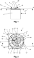
- Figure 1 shows a side view of a device 1 for small-volume bulk material.
- the small-volume bulk material is, for example, a medical product that can be in the form of a tablet, an oblong or a grain.
- the device 1 is used both for separating and for measuring bulk material.
- This device 1 comprises a lower section 2 and an upper section 3.
- the lower section 2 is surrounded by a housing 4.
- In the upper section 3 there is an arrangement for separating 3, whereby the upper section corresponds to the arrangement for separating.
- This arrangement for separating 3 comprises a plate element 5 designed as a vibration plate and an easily removable storage container 6 in which bulk material is stored.
- the storage container 6 can either be firmly connected to the plate element 5 or decoupled from this plate element 5. If the storage container 6 is decoupled from the plate element 5, the storage container 6 can be connected to the housing 4, for example.
- the storage container 6 comprises a small, lower opening 7 in a lower area, through which the bulk material can reach the plate element 5.
- Bulk material is in the Figure 1 not shown. Bulk material can be introduced into the storage container 6 via an upper feed opening (not visible in this view), which is located in an upper area of the storage container 6. For this purpose, bulk material feeders can be attached to the upper area of the storage container 6.
- the storage container 6 has a standard connection 8 in the upper area.
- This standard connection can, for example, be a clamp with which the corresponding bulk material feeder can be attached to the storage container 6.
- a conversion and thus an adaptation of the arrangement for separating to different bulk material feeds is therefore not necessary.
- the device can be used at different locations, i.e. also at locations where there is no space for a conversion or adaptation of the arrangement for separating or where tools for conversion or adaptation are not available.
- the bulk material feed 39 shown is a hose 39 through which bulk material can be introduced into the storage container 6. Since the storage container 6 has a standard connection 8, another bulk material feed, for example a funnel, can also be attached to the storage container 6 quickly and easily.
- the storage container 6 Since the storage container 6 is easy to remove, the storage container 6 can also be filled separately and then placed back on the device 1.
- Figure 2 is a top view of the Figure 1 The device 1 shown is shown in section through a plane S.
- the plate element 5 of the upper section 3 is arranged on the lower section 2 of the device 1.
- the lower opening 7 of the storage container 6 can also be seen through the section, through which the bulk material can reach the plate element 5.
- the bulk material which is in Figure 2 in the form of oblongs, is only partially provided with the reference number 9 for the sake of clarity.
- This bulk material 9 is introduced via a feed opening 10 which is arranged in the upper area of the storage container 6.
- a vibration drive for example a throw conveyor
- the bulk material 9 is moved along a path 14 in the direction of the arrow 11 until it finally reaches an opening 12 and falls downwards.
- the separated bulk material falls into a chamber of a transport device, for example into a chamber of a transport star.
- the transport device with the chambers is located in the lower section 2 and is therefore in Figure 2 not visible.
- the vibration drive is located in the lower section 2, it is in Figure 2 also not visible.
- the track 14 on which the bulk material 9 is transported is preferably divided into several track sections, whereby the track 14 is sufficiently long, so that the bulk material 9 can be separated on the way to the opening 12.
- the track 14 of the plate element 5 is constructed in a spiral shape and has three track sections, namely an inner track section 14', a middle track section 14" and an adjoining outer track section 14"'.
- the boundaries of the individual track sections 14', 14", 14′′′ are marked by dashed lines 16, 17.
- the track 14 is surrounded by an outer wall 15 which prevents the bulk material 9 from falling off the plate element 5. It is understood that the track 14 does not have to be constructed in a spiral shape, but can also have a different structure.
- Figure 3 shows a longitudinal section along AA through the Figure 2 shown device 1, whereby the upper section 3 is again arranged above the lower section 2.
- the upper section 3 is the arrangement for separation 3 and consists of the plate element 5 and the storage container 6, which can either be connected to the plate element 5 or decoupled from it.
- the standard connection 8 can also be seen.
- a bulk material feed is in Figure 3 not shown. Nor was it decided to Figure 3 Bulk material that is transported on the track 14 of the plate element 5 in the direction of the opening 12.
- the size of the lower opening 7 of the storage container 6 can be adjusted, whereby the amount of bulk material dispensed per unit of time can be changed or adapted to the size of the bulk material.
- vibration drive 18 In the lower section 2, directly below the plate element 5, there is the only schematically shown vibration drive 18, which is used not only to transport the bulk material in the direction of the opening 12, but also to separate it on the way there.
- the vibration drive 18 can be a throw conveyor that transports the bulk material and separates it from one another by means of vibration. Vibration drives for transporting bulk material by means of vibration are known, which is why a detailed description of the vibration drive 18 is omitted at this point.
- the vibration drive 18 is laterally surrounded by the transport device 19, wherein the transport device 19 is preferably designed in the shape of a wheel and in particular as a transport star (as in Figure 3 shown) or also designed as a transport rake.
- the transport device 19, designed as a transport star 19, is arranged above a floor 20 and comprises several chambers in which a previously separated bulk material is transported. In the Figure 3 only two chambers 21, 22 are visible.
- a measuring device 23 is provided beneath the base 20, which comprises at least one measuring station, the measuring device 23 being shown only partially and schematically. However, the measuring device 23 preferably comprises several measuring stations so that as many parameters of the bulk material as possible can be measured.
- the chamber 21 of the transport device 19 is located directly below the opening 12 of the plate element 5. This allows a bulk material that falls through the opening 12 to pass directly into the chamber 21 of the transport device 19.
- the opening 12 is equipped with a detector, for example a sound detector, which can detect whether only one bulk material or several bulk materials have entered the chamber.
- the bulk material After the bulk material has fallen into the chamber 21 of the transport device 19 and the detector has determined that only one bulk material has actually entered the chamber 21, the bulk material is guided in a first direction around the vibration drive 18 and above the measuring device 23.
- the bulk material lying in the chamber 21 passes at least the first measuring station of the measuring device 23.
- This first measuring station is preferably a scale.
- the scale detects whether only one bulk material has actually entered chamber 21. If the scale detects that several bulk materials or even only a few fragments of a bulk material have reached the chamber 21, the chamber 21 is emptied. To do this, the transport device 19 is moved back in a second direction, ie in the direction opposite to the first direction. The chamber 21 is moved to a waste container (not visible) which is installed in the floor 20. As soon as the chamber 21 is above the waste container, fragments or the multiple bulk materials fall into this waste container and are thus disposed of.
- the detector and the scale ensure that only one bulk material is measured by the measuring device at a time.
- the measuring device 23 comprises additional measuring stations in addition to the scale, through which a wide variety of parameters can be determined.
- additional measuring stations can be video cameras and/or NIR sensors and/or even a fracture chamber. In this fracture chamber, the width and length of a bulk material can be measured in addition to the hardness.
- the chemical composition or quality of the bulk material is determined using the NIR sensors, whereby four or eight such sensors can be provided, for example.
- Video cameras are used to check whether only one bulk material has actually entered the transport device 19 via the opening 12, or to check whether the bulk material has the desired shape.
- FIG 3 a central axis M is shown running through the device 1, which runs through the center of the device 1.
- the storage container 6 and the vibration drive 18 are arranged on this central axis M.
- the central axis M therefore also runs centrally through the vibration drive 18 and the storage container 6. Therefore, the transport device 19 rotates not only around the vibration drive 18, but also around the central axis M.
- Figure 4 shows a plan view of the lower section 2 of the device 1 after a horizontal section along a plane BB (see Figure 1 ).
- the transport device 19 surrounds the vibration drive 18 from all sides and can to move this vibration drive 18 forward in the direction of arrow 40 or backward in the direction of arrow 41.
- the transport device 19 is in Figure 4 designed as a transport star and has several chambers 21, 22, 24 to 33 that can hold bulk material.
- One bulk material 34 to 38 designed as an oblong is already in each of the chambers 21, 22, 24, 25, 26.
- the other chambers 27 to 33 are empty.
- the bulk material 38 has already been introduced into the chamber 21 via the opening 12 of the plate element 5 from above (see also Figure 3 ).
- This chamber 21 and the bulk material 38 located therein are in a position P0 (starting position). Since the detector attached to the opening 12 (not visible) has determined that there is only one bulk material, the chamber 21 with the bulk material 38 located therein is moved further forward in the direction of the arrow 40 and thus in the direction of the position P10.
- the bulk material 38 first reaches the position P1.
- a first measuring station of the measuring device 23 in the form of a scale is located in the floor 20. The scale is used to determine whether there is actually only one bulk material in the chamber 21.
- the transport device 19 would move back in the direction of the arrow 41 until the chamber 21 reached the position Px.
- the device 19 is then moved forward again in the direction of the arrow 40 until the chamber 21 has reached the starting position P0 again. In this starting position P0, the chamber 21 is again filled with bulk material.
- the transport device 19 is moved further forward in the direction of the arrow 40.
- the bulk material 33 passes through positions P2 to P10 one after the other.
- a further measuring station of the measuring device 23 can be arranged in the floor 20 at each of the positions P2 to P9.
- NIR sensor in the floor 20 as a measuring station.
- Each NIR sensor thus forms a measuring station and is - like the scale at position P1 - part of the measuring device 23.
- the measuring device 23 therefore comprises eight NIR sensors.
- NIR sensors are only provided as measuring stations at positions P2 to P5 in the floor 20 and that the bulk material is measured using video cameras in positions P6 to P9.
- the video cameras are also arranged in the floor 20, with each video camera forming a measuring station.
- the measuring device 23 would also have nine measuring stations, namely a scale, four video cameras and four NIR sensors.
- the transport device 19 is moved further in the direction of the arrow 40 until the chamber 21 with the bulk material 38 located therein has reached the position P10.
- the base 20 preferably has an opening 43 through which the bulk material 38 can be removed, for example because the waste container is arranged below the opening 43.
- the bulk material 38 is fed via the opening 43 to another measuring station, such as a fracture chamber (not visible), which is also located in the lower section 2 of the device 1, but is arranged below the vibration drive 18 and the transport device 19.
- a fracture chamber (not visible)
- a width and a length measurement of the bulk material can also be carried out.
- the transport device 19 can also have more or fewer than just 12 chambers, which means that the transport device can also travel to more or fewer positions.
- a measuring station of a measuring device can be provided at each of the positions traveled to by the transport device, so that the bulk material can be measured in each of the positions.
Landscapes
- Engineering & Computer Science (AREA)
- Mechanical Engineering (AREA)
- Filling Or Emptying Of Bunkers, Hoppers, And Tanks (AREA)
- Feeding Of Articles To Conveyors (AREA)
Applications Claiming Priority (3)
| Application Number | Priority Date | Filing Date | Title |
|---|---|---|---|
| DE102022100828.2A DE102022100828B4 (de) | 2022-01-14 | 2022-01-14 | Vorrichtung für kleinvolumiges Schüttgut |
| EP23701247.1A EP4463406A1 (fr) | 2022-01-14 | 2023-01-12 | Dispositif de séparation et de mesure d'un produit en vrac de petit volume |
| PCT/EP2023/050655 WO2023135219A1 (fr) | 2022-01-14 | 2023-01-12 | Dispositif de séparation et de mesure d'un produit en vrac de petit volume |
Related Parent Applications (2)
| Application Number | Title | Priority Date | Filing Date |
|---|---|---|---|
| EP23701247.1A Division EP4463406A1 (fr) | 2022-01-14 | 2023-01-12 | Dispositif de séparation et de mesure d'un produit en vrac de petit volume |
| EP23701247.1A Division-Into EP4463406A1 (fr) | 2022-01-14 | 2023-01-12 | Dispositif de séparation et de mesure d'un produit en vrac de petit volume |
Publications (2)
| Publication Number | Publication Date |
|---|---|
| EP4467964A2 true EP4467964A2 (fr) | 2024-11-27 |
| EP4467964A3 EP4467964A3 (fr) | 2024-12-25 |
Family
ID=85036552
Family Applications (2)
| Application Number | Title | Priority Date | Filing Date |
|---|---|---|---|
| EP24197161.3A Pending EP4467964A3 (fr) | 2022-01-14 | 2023-01-12 | Dispositif pour produit en vrac de petit volume |
| EP23701247.1A Pending EP4463406A1 (fr) | 2022-01-14 | 2023-01-12 | Dispositif de séparation et de mesure d'un produit en vrac de petit volume |
Family Applications After (1)
| Application Number | Title | Priority Date | Filing Date |
|---|---|---|---|
| EP23701247.1A Pending EP4463406A1 (fr) | 2022-01-14 | 2023-01-12 | Dispositif de séparation et de mesure d'un produit en vrac de petit volume |
Country Status (3)
| Country | Link |
|---|---|
| EP (2) | EP4467964A3 (fr) |
| DE (1) | DE102022100828B4 (fr) |
| WO (1) | WO2023135219A1 (fr) |
Families Citing this family (1)
| Publication number | Priority date | Publication date | Assignee | Title |
|---|---|---|---|---|
| DE102024112966A1 (de) * | 2024-05-08 | 2025-11-13 | Thilo Kraemer | Vorrichtung für kleinvolumiges Schüttgut |
Citations (6)
| Publication number | Priority date | Publication date | Assignee | Title |
|---|---|---|---|---|
| WO1998019945A2 (fr) | 1996-11-08 | 1998-05-14 | Dr. Schleuniger Pharmatron Ag | Appareil a controler les comprimes |
| US20050062466A1 (en) | 2000-07-11 | 2005-03-24 | Murata Manufacturing Co., Ltd. | Electronic part transport device and inspection apparatus using the same |
| EP2664551A1 (fr) | 2012-05-16 | 2013-11-20 | UHLMANN PAC-SYSTEME GmbH & Co. KG | Procédé d'isolation optimisée et de distribution de petits produits pharmaceutiques |
| US20160167866A1 (en) | 2013-07-25 | 2016-06-16 | Tosho, Inc. | Drug feeder |
| US20170137227A1 (en) | 2014-06-30 | 2017-05-18 | Qualysense Ag | Transport apparatus with vacuum belt |
| DE102017114972A1 (de) | 2017-04-03 | 2018-10-04 | Broetje-Automation Gmbh | Verfahren zum Versorgen einer Nietmaschine mit Nietelementen |
Family Cites Families (5)
| Publication number | Priority date | Publication date | Assignee | Title |
|---|---|---|---|---|
| AT412398B (de) | 1990-01-18 | 2005-02-25 | Sticht Walter | Linearfördervorrichtung für einzelteile |
| US7343815B2 (en) | 2003-02-12 | 2008-03-18 | Kraemer Thilo | Quality control device for solid, pharmaceutical products |
| ATE425464T1 (de) * | 2004-09-20 | 2009-03-15 | Thilo Kraemer | Vorrichtung und verfahren zur bestimmung eines parameters von objekten |
| JP5752081B2 (ja) * | 2011-06-09 | 2015-07-22 | 株式会社京都製作所 | 錠剤印刷装置および錠剤印刷方法 |
| EP3730225B1 (fr) * | 2019-04-26 | 2023-09-20 | Thilo Kraemer | Installation de dépoussiérage |
-
2022
- 2022-01-14 DE DE102022100828.2A patent/DE102022100828B4/de active Active
-
2023
- 2023-01-12 WO PCT/EP2023/050655 patent/WO2023135219A1/fr not_active Ceased
- 2023-01-12 EP EP24197161.3A patent/EP4467964A3/fr active Pending
- 2023-01-12 EP EP23701247.1A patent/EP4463406A1/fr active Pending
Patent Citations (6)
| Publication number | Priority date | Publication date | Assignee | Title |
|---|---|---|---|---|
| WO1998019945A2 (fr) | 1996-11-08 | 1998-05-14 | Dr. Schleuniger Pharmatron Ag | Appareil a controler les comprimes |
| US20050062466A1 (en) | 2000-07-11 | 2005-03-24 | Murata Manufacturing Co., Ltd. | Electronic part transport device and inspection apparatus using the same |
| EP2664551A1 (fr) | 2012-05-16 | 2013-11-20 | UHLMANN PAC-SYSTEME GmbH & Co. KG | Procédé d'isolation optimisée et de distribution de petits produits pharmaceutiques |
| US20160167866A1 (en) | 2013-07-25 | 2016-06-16 | Tosho, Inc. | Drug feeder |
| US20170137227A1 (en) | 2014-06-30 | 2017-05-18 | Qualysense Ag | Transport apparatus with vacuum belt |
| DE102017114972A1 (de) | 2017-04-03 | 2018-10-04 | Broetje-Automation Gmbh | Verfahren zum Versorgen einer Nietmaschine mit Nietelementen |
Also Published As
| Publication number | Publication date |
|---|---|
| DE102022100828B4 (de) | 2023-08-10 |
| DE102022100828A1 (de) | 2023-07-20 |
| EP4467964A3 (fr) | 2024-12-25 |
| WO2023135219A1 (fr) | 2023-07-20 |
| EP4463406A1 (fr) | 2024-11-20 |
Similar Documents
| Publication | Publication Date | Title |
|---|---|---|
| DE69706967T2 (de) | Vorrichtung zum wiegen von kleinen gegenständen wie gelatinekapseln | |
| DE69626731T2 (de) | Körnchenbarriere und Körnchenwägeapparat damit | |
| EP2003074B1 (fr) | Dispositif de transport et de tri de pilules | |
| EP2664551A1 (fr) | Procédé d'isolation optimisée et de distribution de petits produits pharmaceutiques | |
| DE3803852C2 (fr) | ||
| EP0685714B1 (fr) | Dispositif pour le pesage de capsules en gélatine dure | |
| EP1952706A1 (fr) | Magasin de vidage et procédé de vidage de récipients remplis de produits en forme de tige, en particulier récipients en forme de colonne | |
| EP2248604B1 (fr) | Dispositif de tri de capsules de médicaments cylindriques dont la géométrie est défectueuse | |
| DE2544888A1 (de) | Zufuehrvorrichtung | |
| EP4467964A2 (fr) | Dispositif pour produit en vrac de petit volume | |
| DE3635138C2 (fr) | ||
| EP0718219A2 (fr) | Dispositif pour individualiser des objets | |
| DE69413003T2 (de) | Verfahren und Vorrichtung zum Wiegen von langgestreckten Teigwaren | |
| EP0295382A2 (fr) | Dispositif pour la séparation, le triage et le transport dans une position alignée de pièces | |
| DE102022005030A1 (de) | Vorrichtung für kleinvolumiges Schüttgut | |
| AT391842B (de) | Vorrichtung zum zufuehren und vereinzeln von montageteilen | |
| DE102015114145A1 (de) | Dosiervorrichtung für granulares Material | |
| DE10133805A1 (de) | Einrichtung zum Zuführen von Bauteilen zu einer Montagestation | |
| EP3380420B1 (fr) | Installation et procédé permettant de séparer et/ou de contrôler des contenants | |
| DE102024112966A1 (de) | Vorrichtung für kleinvolumiges Schüttgut | |
| DE69307049T2 (de) | Verfahren und Vorrichtung zum Zuführen von Teilen | |
| EP0223088A2 (fr) | Balance combinatoire | |
| DE3914360C2 (fr) | ||
| AT397938B (de) | Dübelübernahmestation bei dübeleintreibgeräten | |
| DE2904669C2 (de) | Vorrichtung zum Aussortieren maßhaltiger Bonbons |
Legal Events
| Date | Code | Title | Description |
|---|---|---|---|
| PUAI | Public reference made under article 153(3) epc to a published international application that has entered the european phase |
Free format text: ORIGINAL CODE: 0009012 |
|
| STAA | Information on the status of an ep patent application or granted ep patent |
Free format text: STATUS: THE APPLICATION HAS BEEN PUBLISHED |
|
| REG | Reference to a national code |
Ref country code: DE Ref legal event code: R079 Free format text: PREVIOUS MAIN CLASS: G01N0021000000 Ipc: B65G0047140000 |
|
| PUAL | Search report despatched |
Free format text: ORIGINAL CODE: 0009013 |
|
| AC | Divisional application: reference to earlier application |
Ref document number: 4463406 Country of ref document: EP Kind code of ref document: P |
|
| AK | Designated contracting states |
Kind code of ref document: A2 Designated state(s): AL AT BE BG CH CY CZ DE DK EE ES FI FR GB GR HR HU IE IS IT LI LT LU LV MC ME MK MT NL NO PL PT RO RS SE SI SK SM TR |
|
| AK | Designated contracting states |
Kind code of ref document: A3 Designated state(s): AL AT BE BG CH CY CZ DE DK EE ES FI FR GB GR HR HU IE IS IT LI LT LU LV MC ME MK MT NL NO PL PT RO RS SE SI SK SM TR |
|
| RIC1 | Information provided on ipc code assigned before grant |
Ipc: G01N 21/00 20060101ALI20241119BHEP Ipc: B65G 47/14 20060101AFI20241119BHEP |
|
| STAA | Information on the status of an ep patent application or granted ep patent |
Free format text: STATUS: REQUEST FOR EXAMINATION WAS MADE |
|
| 17P | Request for examination filed |
Effective date: 20250205 |