EP4458733A2 - Procédé d'ouverture d'une poche de transport suspendue dans un chariot ainsi que dispositif d'ouverture de poche permettant la mise en uvre du procédé - Google Patents
Procédé d'ouverture d'une poche de transport suspendue dans un chariot ainsi que dispositif d'ouverture de poche permettant la mise en uvre du procédé Download PDFInfo
- Publication number
- EP4458733A2 EP4458733A2 EP24196460.0A EP24196460A EP4458733A2 EP 4458733 A2 EP4458733 A2 EP 4458733A2 EP 24196460 A EP24196460 A EP 24196460A EP 4458733 A2 EP4458733 A2 EP 4458733A2
- Authority
- EP
- European Patent Office
- Prior art keywords
- carriage
- transport
- bag
- opening
- pivot
- Prior art date
- Legal status (The legal status is an assumption and is not a legal conclusion. Google has not performed a legal analysis and makes no representation as to the accuracy of the status listed.)
- Pending
Links
Images


Classifications
-
- B—PERFORMING OPERATIONS; TRANSPORTING
- B65—CONVEYING; PACKING; STORING; HANDLING THIN OR FILAMENTARY MATERIAL
- B65G—TRANSPORT OR STORAGE DEVICES, e.g. CONVEYORS FOR LOADING OR TIPPING, SHOP CONVEYOR SYSTEMS OR PNEUMATIC TUBE CONVEYORS
- B65G47/00—Article or material-handling devices associated with conveyors; Methods employing such devices
- B65G47/74—Feeding, transfer, or discharging devices of particular kinds or types
- B65G47/78—Troughs having discharge openings and closures
-
- B—PERFORMING OPERATIONS; TRANSPORTING
- B65—CONVEYING; PACKING; STORING; HANDLING THIN OR FILAMENTARY MATERIAL
- B65G—TRANSPORT OR STORAGE DEVICES, e.g. CONVEYORS FOR LOADING OR TIPPING, SHOP CONVEYOR SYSTEMS OR PNEUMATIC TUBE CONVEYORS
- B65G17/00—Conveyors having an endless traction element, e.g. a chain, transmitting movement to a continuous or substantially-continuous load-carrying surface or to a series of individual load-carriers; Endless-chain conveyors in which the chains form the load-carrying surface
- B65G17/20—Conveyors having an endless traction element, e.g. a chain, transmitting movement to a continuous or substantially-continuous load-carrying surface or to a series of individual load-carriers; Endless-chain conveyors in which the chains form the load-carrying surface comprising load-carriers suspended from overhead traction chains
-
- B—PERFORMING OPERATIONS; TRANSPORTING
- B65—CONVEYING; PACKING; STORING; HANDLING THIN OR FILAMENTARY MATERIAL
- B65G—TRANSPORT OR STORAGE DEVICES, e.g. CONVEYORS FOR LOADING OR TIPPING, SHOP CONVEYOR SYSTEMS OR PNEUMATIC TUBE CONVEYORS
- B65G47/00—Article or material-handling devices associated with conveyors; Methods employing such devices
- B65G47/34—Devices for discharging articles or materials from conveyor
- B65G47/36—Devices for discharging articles or materials from conveyor by detaching suspended articles
-
- B—PERFORMING OPERATIONS; TRANSPORTING
- B65—CONVEYING; PACKING; STORING; HANDLING THIN OR FILAMENTARY MATERIAL
- B65G—TRANSPORT OR STORAGE DEVICES, e.g. CONVEYORS FOR LOADING OR TIPPING, SHOP CONVEYOR SYSTEMS OR PNEUMATIC TUBE CONVEYORS
- B65G9/00—Apparatus for assisting manual handling having suspended load-carriers movable by hand or gravity
- B65G9/004—Loading or unloading arrangements
-
- B—PERFORMING OPERATIONS; TRANSPORTING
- B65—CONVEYING; PACKING; STORING; HANDLING THIN OR FILAMENTARY MATERIAL
- B65G—TRANSPORT OR STORAGE DEVICES, e.g. CONVEYORS FOR LOADING OR TIPPING, SHOP CONVEYOR SYSTEMS OR PNEUMATIC TUBE CONVEYORS
- B65G19/00—Conveyors comprising an impeller or a series of impellers carried by an endless traction element and arranged to move articles or materials over a supporting surface or underlying material, e.g. endless scraper conveyors
- B65G19/02—Conveyors comprising an impeller or a series of impellers carried by an endless traction element and arranged to move articles or materials over a supporting surface or underlying material, e.g. endless scraper conveyors for articles, e.g. for containers
- B65G19/025—Conveyors comprising an impeller or a series of impellers carried by an endless traction element and arranged to move articles or materials over a supporting surface or underlying material, e.g. endless scraper conveyors for articles, e.g. for containers for suspended articles
-
- B—PERFORMING OPERATIONS; TRANSPORTING
- B65—CONVEYING; PACKING; STORING; HANDLING THIN OR FILAMENTARY MATERIAL
- B65G—TRANSPORT OR STORAGE DEVICES, e.g. CONVEYORS FOR LOADING OR TIPPING, SHOP CONVEYOR SYSTEMS OR PNEUMATIC TUBE CONVEYORS
- B65G47/00—Article or material-handling devices associated with conveyors; Methods employing such devices
- B65G47/52—Devices for transferring articles or materials between conveyors i.e. discharging or feeding devices
- B65G47/60—Devices for transferring articles or materials between conveyors i.e. discharging or feeding devices to or from conveyors of the suspended, e.g. trolley, type
- B65G47/61—Devices for transferring articles or materials between conveyors i.e. discharging or feeding devices to or from conveyors of the suspended, e.g. trolley, type for articles
-
- B—PERFORMING OPERATIONS; TRANSPORTING
- B65—CONVEYING; PACKING; STORING; HANDLING THIN OR FILAMENTARY MATERIAL
- B65G—TRANSPORT OR STORAGE DEVICES, e.g. CONVEYORS FOR LOADING OR TIPPING, SHOP CONVEYOR SYSTEMS OR PNEUMATIC TUBE CONVEYORS
- B65G47/00—Article or material-handling devices associated with conveyors; Methods employing such devices
- B65G47/74—Feeding, transfer, or discharging devices of particular kinds or types
- B65G47/88—Separating or stopping elements, e.g. fingers
- B65G47/8807—Separating or stopping elements, e.g. fingers with one stop
- B65G47/8823—Pivoting stop, swinging in or out of the path of the article
-
- B—PERFORMING OPERATIONS; TRANSPORTING
- B65—CONVEYING; PACKING; STORING; HANDLING THIN OR FILAMENTARY MATERIAL
- B65H—HANDLING THIN OR FILAMENTARY MATERIAL, e.g. SHEETS, WEBS, CABLES
- B65H2301/00—Handling processes for sheets or webs
- B65H2301/40—Type of handling process
- B65H2301/43—Gathering; Associating; Assembling
- B65H2301/432—Gathering; Associating; Assembling in pockets, i.e. vertically
Definitions
- the present invention relates to the field of conveyor technology. It relates to a method for opening a transport bag hanging on a carriage according to the preamble of claim 1.
- the publication EP 2 130 968 B1 relates to a transport bag and a conveyor system for a transport bag.
- the transport bag consists of a support wall that is at least dimensionally stable and is equipped with at least one coupling in its lower area and is provided with means for releasing the coupling in its upper area.
- the bottom-side wall is flexible at least in its lower area and has counter-coupling means that can be brought into engagement with the coupling so that the transport bag can be closed at the bottom. When the coupling is opened, the transport bag opens downwards and releases the transported goods.
- the associated conveyor system has a conveyor rail with carriers that can be moved in a conveying direction for receiving a carrying hook each, a closing station for coupling the counter-coupling means of the flexible bottom-side wall with the at least one coupling of the carrying wall, a loading station with means for lifting the brackets for distancing the bottom-side wall from the carrying wall against the conveying direction and an unloading station with means for triggering the means for opening the coupling.
- the publication DE 10 2012 108 757 A1 relates to a carrying bag for a hanging conveyor device for the hanging transport of objects as well as a closing mechanism for closing a carrying bag and a hanging conveyor device. It discloses a carrying bag for a hanging conveyor device for the hanging transport of objects, comprising a holding frame, a bag that hangs on the holding frame and can hold objects to be transported, and a hanging element that is connected to the holding frame and by means of which the carrying bag can be attached to a hanging conveyor device in order to be transported in a hanging manner by the hanging conveyor device, the bag having a first and a second bag section that is, for example, materially separate from one another, which each have a bag end section connected to the holding frame and a second bag end section facing away from the holding frame, the second bag end sections being connected to one another via a joint mechanism that can be brought into an unloading position (by pivoting about a pivot axis), in which the second bag end sections are arranged at a distance from one another, so that the bag can be used
- B. for dispensing vertically downwards is provided with an outlet opening formed between the second bag end sections, and which can be brought into a loading position (by pivoting about a pivot axis) in which the second bag end sections are arranged adjacent to each other, so that the Outlet opening is closed and the pocket bag can accommodate objects, i.e. hold them in/inside it.
- the publication DE 10 2008 061 685 A1 relates to a loading station for transport bags transported in an overhead conveyor system.
- the loading station has an upper feed rail for the transport bags, a vertical conveyor connected to the feed rail for feeding the transport bags into a lower loading position, a device for opening the transport bags in the loading position and a lower discharge rail connected to the vertical conveyor for discharging the transport bags from the loading position.
- the bag is opened by a guide during the movement into the loading position.
- the publication DE 10 2004 018 569 A1 relates to a collecting device for the sorting collection of objects, in particular items of clothing, and a conveyor device for transporting the collecting device.
- the collecting device is characterized by a collecting bag which essentially has a frame provided with a carrier element which can be integrated into a conveyor device and a bag hanging on the frame, wherein the carrier element and the frame can be pivoted relative to one another about an axis which is transverse to the conveying direction, and wherein when the frame is arranged horizontally the bag is opened and when the frame is arranged vertically the bag is collapsed and essentially closed.
- the publication DE 10 2013 205 172 A1 discloses a transport bag for hanging transport of goods.
- the transport bag has a rigid support wall, which in its upper section in the transport position is connected to a support element for hanging carrying of the transport bag.
- a flexible goods holding wall forms with the support wall a carrying bag that is closed downwards and on two opposite sides at least in the transport position of the transport bag.
- the supporting wall is connected to the retaining wall between an upper wall connecting section in the transport position and a lower wall connecting section in the transport position in such a way that a length of the web-shaped retaining wall between the two wall connecting sections can be variably adapted to the transport of different goods.
- the transport bag is designed in such a way that this length adjustment of the retaining wall takes place by a relative displacement of the retaining wall to the supporting wall at least in the area of one of the two connecting sections.
- the publication DE 10 2010 033 905 A1 concerns a conveyor system with carrying bags for conveyed material.
- the conveyor system comprises a stationary conveyor rail with drivers moved in a conveying direction for receiving a suspension point for each of the carrier bags, the carrier bag with a bag bag for receiving the goods to be conveyed, the bag bag having rectangularly arranged wide and narrow side walls with the dimensions a, b, the bag bag with a support frame which has a pull rod with the suspension point formed at the upper end and which spans a loading window for the bag, the support frame with a pressure piece extending parallel to the wide side walls, a coupling located between the driver and the support frame for setting a stable rotational position of the carrier bag relative to the driver, in which the carrier bag assumes a position with the loading window transverse to the conveying direction and for setting an unstable rotational position of the carrier bag relative to the driver, in which the carrier bag assumes a position with the loading window parallel to the conveying direction, the unstable rotational position being caused by the pressure piece engaging with a stationary
- the publication DE 10 2014 203 298 A1 relates to a hanging conveyor for transporting goods in hanging bags.
- the hanging conveyor comprises a plurality of hanging bags, each with a first bag side wall and a second bag side wall, which are connected to one another in a folding connection area in such a way that they can be folded out and folded together to open and close a goods receiving area, and with a suspension means for hanging the hanging bag on the hanging conveyor, wherein the first bag side wall is connected to the suspension means so as to be pivotable about a bag pivot axis that runs at least approximately horizontally in a transport position of the hanging bag, and the second bag side wall is connected to the suspension means or can be acted upon by it in such a way that the bag side walls can be folded out and folded together by pivoting the first bag side wall about the bag pivot axis, wherein the hanging conveyor further comprises a guide rail arrangement for the guided movement of the hanging bags in their transport position and a loading station for the hanging bags, with a loading platform that is positioned below the guide rail arrangement.
- the publication WO 2015/124525 A1 relates to a hanging bag as a conveying goods container for transporting conveying goods in a hanging conveyor.
- the hanging bag comprises a first bag side wall and a second bag side wall, which delimit a conveying goods receiving area between them and are connected to one another in a folding connection area in such a way that they can be folded out and folded together to open and close the conveying goods receiving area, and a suspension means for hanging the hanging bag on a guide rail arrangement of a hanging conveyor, wherein the first bag side wall has a rigid edge contour region and is connected to the suspension means so as to be pivotable about a pivot axis, and wherein the second pocket side wall is connected to the suspension means or can be acted upon by it in such a way that the first and second pocket side walls can be folded apart and folded together by pivoting the first pocket side wall about the pivot axis.
- the hanging pocket has a base assembly and a change element, wherein the base assembly has the suspension means and the rigid edge contour region, and wherein the change element comprises at least part of the second pocket side wall, preferably the entire second pocket side wall, and is provided so as to be replaceable on the base assembly.
- the publication DE 10 2011 015 138 B4 discloses a suspended conveyor transport bag for automatically unloading a loaded piece of goods with a base body and a separate receptacle connected thereto, wherein the base body has a top, a bottom, lateral sides and front sides, wherein the receptacle has a bottom, a top, front sides and lateral sides, wherein the unloading of the transport bag takes place through one of the front sides of the base body, which is open, wherein an opposite front side is preferably also open, wherein the bottom of the base body couples to the top of the receptacle in order to define a receiving space below the base body, and wherein the bottom of the base body, in particular in an unloaded state of the transport bag, is open, wherein the top of the receptacle is open in the unloaded state of the transport bag, wherein at least the lateral sides of the base body, the lateral sides of the receptacle and the bottom of the receptacle are closed and wherein at least the
- the publication DE 10 2012 018 925 A1 discloses a pocket overhead conveyor system with a overhead conveyor for transporting pockets along a guide rail downstream in a conveying direction, wherein the pockets hang vertically below the guide rail in a transport position and wherein the pockets are aligned substantially horizontally in a loading position, with a loading station which has a deflection device, wherein the deflection device has an upstream end and a downstream end and is arranged below the guide rail of the overhead conveyor, wherein the pockets come into contact with the deflection device during transport in the conveying direction in order to rotate the pockets at least initially during continued transport in the conveying direction from the vertical transport position to the substantially horizontal loading position, and with a pocket, wherein the pocket has a suspension device for pivotably coupling the pocket to the guide rail of the overhead conveyor, a rear side which has an upper section and a lower section in the vertical transport position, wherein the lower section adjoins the upper section in a longitudinal direction of the rear side, a cover, a front side and a base wherein the
- the method according to the invention for opening a transport bag which, for the transport of goods, moves in a transport direction while hanging on a carriage along a guide rail extending in a transport direction is characterized in that the carriage with the transport bag hanging thereon is stopped in its forward movement at a predetermined point on the guide rail for opening the transport bag, and that the transport bag of the carriage is opened for loading and/or unloading goods to be transported.
- the transport bags to be opened are stopped and opened individually.
- the carriage's transport bag can only be opened for loading and/or unloading of goods to be transported when the carriage is already in its rest position.
- the transport bag of the carriage can also have a swivel frame at the upper end, which can be swiveled to open or close the transport bag.
- the arrival of the carriage in its rest position is detected by means of a carriage detector, and the carriage detector sets an opening mechanism in motion when it detects a carriage in the rest position.
- the transport bag can have a material web attached to the swivel frame at both ends to form a downwardly hanging carrying loop, wherein the two ends of the carrying loop are arranged one behind the other in the direction of transport, wherein the swivel frame on the carriage can be swiveled about a first swivel axis oriented transversely to the direction of transport between a first position in which the transport bag is closed and a second position in which the transport bag is open, and wherein the swivel frame on the carriage is swiveled from the first to the second position by an opening mechanism for loading and/or unloading goods to be transported and is held in the second position.
- the transport bag is essentially limited on the outside by the two vertical sections of the material web, which form two bag walls.
- the transport bag is open when the two bag walls are far enough apart to allow goods to be placed in or removed from the space between them.
- the transport bag is closed when the bag walls are so close to each other that it is practically impossible to fill or remove goods.
- the opening mechanism may comprise an element that can be moved to open the transport bag.
- the goods to be transported can be loaded and unloaded across the direction of transport through openings on the side of the transport bag. However, it is also possible to load and unload the transport bag from above.
- the carriage with the transport bag hanging on it can be released at the predetermined point on the guide rail, and after release, the swivel frame swivels back about the first swivel axis from the second position to the first position.
- the swivel frame can swing back automatically due to gravity.
- the transport bag hanging on the carriage can move past the opening mechanism with its swivel frame in the second position, whereby the swivel frame only swings back from the second position to the first position after passing the opening mechanism.
- the carriage with the transport bag attached to it can also be given a movement impulse in the direction of transport after release.
- the movement impulse can be given by means of a stationary, pivoting transport lever, which is briefly brought into engagement with the carriage.
- the bag opening device is characterized by a first device arranged in the region of the guide rail for stopping a carriage and at least one opening mechanism arranged in the region of the guide rail for opening a transport bag hanging on a stopped carriage.
- the first device and the opening mechanism are connected to each other in terms of control technology.
- Another embodiment is characterized in that the first device and the opening mechanism are arranged laterally of the guide rail.
- the first device and the opening mechanism can be arranged on opposite sides of the guide rail.
- both devices can be arranged on the same side of the guide rail if there is sufficient space for this.
- a pair of similar opening mechanisms can also be arranged in mirror image on opposite sides of the guide rail.
- Such a paired opening mechanism is particularly suitable when the swivel frame of the transport bag is difficult to swivel due to its size, weight or the contents of the bag.
- a further embodiment of the invention is characterized in that the first device has a movable stop element which, in a first position, stops an incoming carriage at a predetermined point on the guide rail and, in a second position, releases a carriage stopped there.
- the movable stop element can be pivotally mounted about a first pivot axis oriented transversely to the conveying direction and can be pivotable about the first pivot axis between the first position and the second position.
- the movable stop element can also be assigned a transport lever which can be pivoted together with the stop element about the first pivot axis and which, when a stopped carriage is released by the stop element, simultaneously gives the carriage a movement impulse in the transport direction.
- a further embodiment of the invention is characterized in that a carriage detector is arranged within the first device at the predetermined point of the guide rail, which detects a stopped carriage, and that the carriage detector is connected to the opening mechanism in terms of control technology.
- the transport bag has a material web attached to a swivel frame at both ends to form a downwardly hanging carrying loop that forms a front and a rear wall, the two ends of the carrying loop being arranged one behind the other in the conveying direction, that the swivel frame on the carriage can be swiveled about a second swivel axis oriented transversely to the conveying direction between a first position in which the transport bag is closed and a second position in which the transport bag is open, and that the opening mechanism has a swivel lever that can be swiveled about a third swivel axis oriented transversely to the conveying direction, which is arranged on the edge of the movement path of the swivel frame of a conveyed transport bag and is equipped at its free end with a driver that can be brought into engagement with the swivel frame in order to move the swivel frame on the carriage for loading and/or unloading
- the pivot lever can be pivoted between a rest position and an opening position, wherein the driver on the pivot lever of the opening mechanism is located in front of the pivot frame of a stopped transport bag in the rest position, and in the opening position occupies a position between the front and rear walls of the transport bag.
- the pivoting range of the pivot lever can also extend below the third pivot axis and can be, for example, 90° or 180° between the rest position and the opening position.
- an actuator in particular a linear one, for example a linearly movable piston rod, instead of a pivot lever to pivot the pivot frame.
- An opening screw can also be used to pivot the pivot frame, which is guided to the pivot frame from the side and pivots it into the opening position by sliding on the increasing radius of the screw. It is also conceivable to provide an automatically operating gripper that grasps the pivot frame outside the pivot axis and pivots it into the opening position.
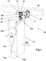
- Fig. 1 is a perspective side view of an embodiment of the bag opening device according to the invention, wherein only the transport bag and the actual opening mechanism that engages with the carrying bag are shown.
- the pocket opening device 10 of the Fig. 1 is mounted on a support structure 20, which is arranged next to the actual guide rail 11 for transport.
- the support structure 20 comprises a square tube; however, it can also be designed differently.
- the guide rail 11 is designed symmetrically to a vertical center plane and has two opposite, U-shaped side channels 11a and 11c as well as a lower, also U-shaped center channel 11b in which a carriage 12 with several wheels runs and is guided.
- the guide channel 11 and the carriage 12 can be designed as described in the publications WO 2016/030275 A1 and WO 2016/030274 A1 described and explained.
- a laterally protruding, pin- or bolt-shaped engagement element 13 is attached at the top between two running wheels, which will be referred to further below in connection with a lever mechanism 16 ( Fig. 5 and 6 ) is discussed.
- a support element 14 is firmly attached, which is designed as an angle plate and at the lower end receives and fixes a tubular frame bearing 14a, which has a transverse to the direction of transport BR (single arrow in Fig. 1 ) oriented pivot axis 15c is defined for a pivot frame 15b pivotally mounted in the frame bearing 14a.
- the swivel frame 15b which in the embodiment shown is designed as a mechanically stable, essentially rectangular wire frame, is part of the transport bag 15, which hangs firmly and with constant orientation (pivot axis 15c transverse to the direction of transport BR) on the carriage 12 via the frame bearing 14a and the support element 14.
- the transport bag 15 comprises a material web, e.g. made of a (reinforced or non-reinforced) fabric, a (laminated or unlaminated) film or another suitable material, which is attached to the swivel frame 15b at both ends to form a downwardly hanging carrying loop 15a.
- the two ends of the carrying loop 15a are arranged one behind the other in the direction of transport, so that the edges of the carrying loop 15a are not connected to one another on the sides except for short deflection supports 15d attached in the lower deflection area.
- the swivel frame 15b which is guided by pockets formed at the ends of the material web, is pivotable about the pivot axis 15c between a first position in which the transport bag 15 is closed (solid line in Fig. 1 ; Fig. 4a ), and a second position in which the transport bag 15 is open (dotted line in Fig. 1 ; Fig. 4b ), pivotable.
- the closed position of the swivel frame 15b the transport bag 15 is transported on the guide rail 11 in the transport direction BR.
- the carriage 12 with the transport bag 15 is stopped and the opened transport bag 15 can be moved in the access direction ZR (double arrow in Fig. 1 ) can be loaded or unloaded from one side or the other.
- the transport or conveyor system shown with the guide rail 11 and the bag opening device 10 arranged at a predetermined location on the guide rail 11 generally comprises a plurality of similar carriages 12 and associated transport bags 15.
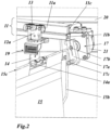
- an information carrier 19 can be firmly attached to the carriage 12, which has a, in particular contains machine-readable, usually coded information that can be read optically, magnetically or radio-technically (eg as RFID).
- the information carrier 19 comprises a bar code which is read in the area of the opening device 10 by a data exchange or reading device 22 ( Fig. 5 ) can be (optically) scanned and read out.
- an opening mechanism 17 which has a pivot lever 17a which can be pivoted about a pivot axis 17b oriented transversely to the conveying direction BR and which is arranged on the edge of the movement path of the pivot frame 15b of a transported transport bag 15.
- the pivot lever 17a is equipped with a driver 17c which projects parallel to the pivot axis 17b into the movement path of the pivot frame 15b and which can be brought into engagement with the pivot frame 15b in order to pivot the pivot frame 15b on the carriage 12 from the first to the second position for loading and/or unloading goods to be transported and to hold it in the second position (see in particular Fig. 4 ).
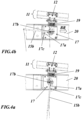
- the pivot lever 17a is between a rest position ( Fig. 4a ) and an opening position ( Fig. 4b ), whereby the driver 17c on the pivot lever 17a of the opening mechanism 17 is in the rest position in the transport direction BR in front of the pivot frame 15b of a stopped transport bag 15 ( Fig. 4a ), and in the opening position occupies a position between the front and rear wall of the transport bag 15 ( Fig. 4b ).
- the pivoting range of the pivot lever 17a extends below the pivot axis 17b and is 90° or more between the rest position and the opening position.
- the pivoting of the pivot lever 17a can by a rotary drive 21, which in this case operates hydraulically or pneumatically.
- the transport bag 15 is returned to the closed position by sliding its swivel frame 15b over the driver 17c in the transport direction BR.
- This can be done passively by the holding means holding the carriage 12 (stopping element 16d in Fig. 6 ) and the carriage 12 is set in motion on an inclined rail section by gravity.
- this can also be done actively by actively giving the carriage 12 a movement impulse in addition to and at the same time as the holding means are released (transport lever 16a in Fig. 5 and 6 ).
- the swivel frame 15b has been moved completely over the carrier 17c in the direction of transport BR, it automatically swivels due to gravity into the Fig.
- the Fig. 4 The opening process shown takes place after the carriage 12 with the transport bag 15 to be opened has been stopped at a predetermined position in the area of the opening mechanism 17.
- This predetermined position is selected so that the pivot lever 17a with the driver 17c relative to the pivot frame 15b exactly the position shown in Fig. 4a shown position.
- the mechanical conditions are particularly favorable when the pivot axis 15c of the pivot frame and the pivot axis 17b of the opening mechanism coincide.
- a lever mechanism 16 is arranged which, on the one hand, precisely stops the carriage 12 and also releases it again, and, on the other hand, gives the carriage 12, which is later released again, a movement impulse which sets BR in motion in a targeted manner in the direction of transport.
- the lever mechanism 16 comprises two levers that can be pivoted together about a common pivot axis 16b, namely a lever-shaped stop element 16d and a transport lever 16a.
- a pivot mechanism 16c engages the larger transport lever 16a, which is preferably actuated pneumatically or hydraulically and causes the pivoting process of the two levers 16a and 16d.
- Fig. 6 shows the stop element 16d (together with the transport lever 16a) in the stop position. In this position, a carriage 12 coming from the right moves with its engagement element 13 - without coming into conflict with the transport lever 16a - against the stop element 16d and stops at this point.
- the stopped carriage 12 can be immediately detected by a carriage detector 18 arranged above the guide rail 11 and the detection signal can be forwarded to a control (not shown), which then activates the opening mechanism 17 and thus initiates the pivoting of the pivot frame 15b by means of the opening mechanism.
- both levers 16a and 16d are quickly pivoted upwards in the direction of transport. This results in the stopping element 16d clearing the way for the stopped carriage 12, and the upwardly pivoting transport lever 16a simultaneously engaging the engagement element 13 on the carriage 12 with its bent transport element 16e formed on the free end. and thereby gives the carriage 12 a movement impulse in the direction of transport BR (on the opposite side, the raised swivel frame slides over the driver 17c of the opening mechanism 17 in this phase). The levers 16a and 16d then swing back into the Fig. 6 shown starting position and are ready to stop a subsequent carriage.
Landscapes
- Engineering & Computer Science (AREA)
- Mechanical Engineering (AREA)
- Supplying Of Containers To The Packaging Station (AREA)
- Chain Conveyers (AREA)
Applications Claiming Priority (2)
| Application Number | Priority Date | Filing Date | Title |
|---|---|---|---|
| CH01171/16A CH712895A1 (de) | 2016-09-09 | 2016-09-09 | Verfahren zum Öffnen einer an einem Laufwagen hängenden Transporttasche sowie Taschenöffnungsvorrichtung zur Durchführung des Verfahrens. |
| EP17189731.7A EP3293130B1 (fr) | 2016-09-09 | 2017-09-07 | Procédé d'ouverture d'une poche de transport suspendue dans un chariot ainsi que dispositif d'ouverture de poche permettant la mise en uvre du procédé |
Related Parent Applications (3)
| Application Number | Title | Priority Date | Filing Date |
|---|---|---|---|
| EP17189731.7A Division EP3293130B1 (fr) | 2016-09-09 | 2017-09-07 | Procédé d'ouverture d'une poche de transport suspendue dans un chariot ainsi que dispositif d'ouverture de poche permettant la mise en uvre du procédé |
| EP17189731.7A Previously-Filed-Application EP3293130B1 (fr) | 2016-09-09 | 2017-09-07 | Procédé d'ouverture d'une poche de transport suspendue dans un chariot ainsi que dispositif d'ouverture de poche permettant la mise en uvre du procédé |
| EP17189731.7A Division-Into EP3293130B1 (fr) | 2016-09-09 | 2017-09-07 | Procédé d'ouverture d'une poche de transport suspendue dans un chariot ainsi que dispositif d'ouverture de poche permettant la mise en uvre du procédé |
Publications (2)
| Publication Number | Publication Date |
|---|---|
| EP4458733A2 true EP4458733A2 (fr) | 2024-11-06 |
| EP4458733A3 EP4458733A3 (fr) | 2025-04-23 |
Family
ID=59811141
Family Applications (2)
| Application Number | Title | Priority Date | Filing Date |
|---|---|---|---|
| EP24196460.0A Pending EP4458733A3 (fr) | 2016-09-09 | 2017-09-07 | Procédé d'ouverture d'une poche de transport suspendue dans un chariot ainsi que dispositif d'ouverture de poche permettant la mise en uvre du procédé |
| EP17189731.7A Active EP3293130B1 (fr) | 2016-09-09 | 2017-09-07 | Procédé d'ouverture d'une poche de transport suspendue dans un chariot ainsi que dispositif d'ouverture de poche permettant la mise en uvre du procédé |
Family Applications After (1)
| Application Number | Title | Priority Date | Filing Date |
|---|---|---|---|
| EP17189731.7A Active EP3293130B1 (fr) | 2016-09-09 | 2017-09-07 | Procédé d'ouverture d'une poche de transport suspendue dans un chariot ainsi que dispositif d'ouverture de poche permettant la mise en uvre du procédé |
Country Status (4)
| Country | Link |
|---|---|
| US (2) | US10322887B2 (fr) |
| EP (2) | EP4458733A3 (fr) |
| CH (1) | CH712895A1 (fr) |
| ES (1) | ES2991588T3 (fr) |
Families Citing this family (27)
| Publication number | Priority date | Publication date | Assignee | Title |
|---|---|---|---|---|
| CH710650A1 (de) | 2015-01-26 | 2016-07-29 | Ferag Ag | Transportvorrichtung, insbesondere in Form eines Hängeförderers. |
| CH712895A1 (de) | 2016-09-09 | 2018-03-15 | Ferag Ag | Verfahren zum Öffnen einer an einem Laufwagen hängenden Transporttasche sowie Taschenöffnungsvorrichtung zur Durchführung des Verfahrens. |
| CH713398A1 (de) * | 2017-01-31 | 2018-07-31 | Ferag Ag | Vorrichtung zum Entleeren hängend geförderter Transporttaschen. |
| DE202017100206U1 (de) | 2017-01-16 | 2018-04-17 | Tgw Mechanics Gmbh | Fördergutbehälter mit Auswerfvorrichtung und zugehörige Hängefördervorrichtung |
| US11878876B2 (en) | 2017-01-31 | 2024-01-23 | Ferag Ag | Device for emptying transport bags conveyed in a suspended manner |
| AT520517B1 (de) * | 2018-04-13 | 2019-05-15 | Tgw Mechanics Gmbh | Entladestation und Verfahren zum Entladen eines mit einem Fördergut beladenen Fördergutbehälters |
| CH715134A1 (de) * | 2018-06-28 | 2019-12-30 | Ferag Ag | Vorrichtung und Verfahren zur Inspektion von hängend förderbaren Transporttaschen. |
| US10737889B2 (en) * | 2018-10-29 | 2020-08-11 | Intelligrated Headquarters, Llc | Pouch conveyor |
| AT521961B1 (de) * | 2019-01-25 | 2020-07-15 | Tgw Mechanics Gmbh | Fördergutbehälter für eine Hängefördervorrichtung und Entladestation zum Entladen desselben |
| AT522665B1 (de) | 2019-05-22 | 2021-12-15 | Tgw Mechanics Gmbh | Hängefördersystem und Verfahren zum Bestimmen der Dicke einer Hängetasche |
| CH716519A1 (de) | 2019-08-22 | 2021-02-26 | Ferag Ag | Vorrichtung und Verfahren zum Transferieren von Waren-Einheiten in Fördereinheiten und/oder aus Fördereinheiten eines Hängefördersystems. |
| KR102330957B1 (ko) * | 2019-12-17 | 2021-11-25 | 주식회사 에스에프에이 | 포켓 소팅 시스템 |
| KR102330956B1 (ko) * | 2019-12-17 | 2021-11-25 | 주식회사 에스에프에이 | 포켓 소팅 시스템 |
| KR102330955B1 (ko) * | 2019-12-17 | 2021-11-25 | 주식회사 에스에프에이 | 포켓 소팅 시스템 |
| KR102330958B1 (ko) * | 2019-12-17 | 2021-11-25 | 주식회사 에스에프에이 | 포켓 소팅 시스템 |
| US12012244B2 (en) | 2020-06-02 | 2024-06-18 | Laitram, L.L.C. | Sorting system sorting packages into bags |
| KR102436161B1 (ko) * | 2020-08-12 | 2022-08-25 | 주식회사 에스에프에이 | 포켓 소팅 시스템 |
| KR102436162B1 (ko) * | 2020-08-12 | 2022-08-25 | 주식회사 에스에프에이 | 포켓 소팅 시스템 |
| CN112110155A (zh) * | 2020-10-28 | 2020-12-22 | 浙江瑞晟智能科技股份有限公司 | 原点驱动器判定方法、驱动器标识方法及系统 |
| CN112255985A (zh) * | 2020-10-28 | 2021-01-22 | 浙江瑞晟智能科技股份有限公司 | 主线标识方法及系统 |
| WO2022218480A1 (fr) * | 2021-04-16 | 2022-10-20 | BEUMER Group GmbH & Co. KG | Station de chargement pour un convoyeur aérien comprenant des poches de transport pour des marchandises à convoyer |
| WO2023095049A1 (fr) | 2021-11-29 | 2023-06-01 | Ferag Ag | Dispositif de gestion du chargement d'unités de transport d'un système d'acheminement |
| EP4286303A1 (fr) | 2022-05-31 | 2023-12-06 | Ferag Ag | Dispositif et procédé pour introduire des unités de marchandises dans un récipient de transport |
| US12246872B2 (en) | 2022-05-31 | 2025-03-11 | Ferag Ag | Device and method for loading transport containers |
| NL2033626B1 (nl) | 2022-11-28 | 2024-06-04 | Vanderlande Ind Bv | Systeem voor het selectief met discrete producten beladen van zakken. |
| CH721145A1 (de) | 2023-09-21 | 2025-03-31 | Ferag Ag | Vorrichtung, verfahren und system zum stabilisieren und beladen von transporttaschen |
| CH721462A1 (de) | 2023-12-22 | 2025-06-30 | Ferag Ag | Anlage und Verfahren zum Sortieren und Zwischenspeichern von Stückgütern |
Citations (12)
| Publication number | Priority date | Publication date | Assignee | Title |
|---|---|---|---|---|
| DE102004018569A1 (de) | 2004-04-16 | 2005-11-03 | Gärtner, Franz | Sammeleinrichtung zum sortierenden Sammeln von Objekten sowie Fördervorrichtung zum Transport der Sammeleinrichtung |
| DE102008061685A1 (de) | 2008-12-11 | 2010-06-17 | Dürkopp Adler AG | Belade-Station für in einer Hänge-Förder-Anlage transportierte Transport-Taschen |
| EP2130968B1 (fr) | 2008-06-04 | 2010-09-15 | Dürkopp Fördertechnik GmbH | Sac de transport et installation de convoyage pour un sac de transport |
| DE102010033905A1 (de) | 2010-08-10 | 2012-02-16 | Dürkopp Fördertechnik GmbH | Förderanlage mit Tragetaschen für Fördergut |
| DE102012018925A1 (de) | 2012-09-18 | 2014-03-20 | SSI Schäfer PEEM GmbH | Tasche für Hängeförderer, Beladestation, Entladestation und Taschen-Hängeförderanlage |
| DE102012108757A1 (de) | 2012-09-18 | 2014-03-20 | Psb Intralogistics Gmbh | Tragetasche für eine Hängefördervorrichtung für den hängenden Transport von Objekten, Schließmechanismus zum Schließen einer Tragetasche und Hängefördervorrichtung |
| DE102011015138B4 (de) | 2011-03-17 | 2014-05-08 | SSI Schäfer PEEM GmbH | Hängeförder-Transporttasche und Verfahren zum automatisierten Entladen der Transporttasche |
| DE102013205172A1 (de) | 2013-03-22 | 2014-09-25 | Dürkopp Fördertechnik GmbH | Transporttasche zum hängenden Transport von Waren |
| DE102014203298A1 (de) | 2014-02-24 | 2015-08-27 | Rsl Logistik Gmbh & Co. Kg | Hängefördereinrichtung mit Ladestation |
| WO2015124525A1 (fr) | 2014-02-24 | 2015-08-27 | Rsl Logistik Gmbh & Co. Kg | Sac suspendu muni d'un élément remplaçable |
| WO2016030275A1 (fr) | 2014-08-27 | 2016-03-03 | Ferag Ag | Chariot pour un convoyeur, notamment pour un convoyeur par gravité, système convoyeur et procédé de fonctionnement de ce dernier |
| WO2016030274A1 (fr) | 2014-08-27 | 2016-03-03 | Ferag Ag | Rail de roulement et son procédé de fabrication |
Family Cites Families (43)
| Publication number | Priority date | Publication date | Assignee | Title |
|---|---|---|---|---|
| GB733714A (en) | 1953-03-12 | 1955-07-20 | Prep Ind Combustibles | Improvements in or relating to endless conveyors |
| US3338179A (en) | 1964-10-12 | 1967-08-29 | Richard W Klemm | Lift mechanism for rail conveyors |
| DE1233777B (de) | 1965-06-01 | 1967-02-02 | Werner Busch | Gehaenge-Foerderband |
| US3533499A (en) | 1968-05-20 | 1970-10-13 | Hewitt Robins Inc | Friction drive assembly |
| CH507828A (de) | 1969-05-09 | 1971-05-31 | Von Roll Ag | Vorrichtung zur schwenkbaren Lagerung eines Lastbehälters an einem Fahrwerk von Hängebahnen |
| DE2221318A1 (de) | 1972-04-29 | 1973-11-15 | Jung Gmbh Lokomotivfab Arn | Behaelter zum foerdern von massenguetern |
| US3807314A (en) | 1973-03-30 | 1974-04-30 | Us Army | Magnetic trolley conveyor system |
| US4079840A (en) | 1976-10-06 | 1978-03-21 | Usner Daniel C | Clothes hanger bridle for a garment trolley bar |
| US4104156A (en) | 1977-06-13 | 1978-08-01 | Fletcher John K | Detachable sling letdown apparatus for lumber sorter |
| DE8133433U1 (de) | 1981-11-12 | 1982-03-18 | Danneberg, Joerg, 8500 Nuernberg | Vorrichtung zum transport eines Wäschesacks mittels einer Hänge-Rollenbahn |
| GB2164628B (en) | 1984-09-17 | 1987-12-02 | Gerber Garment Technology Inc | Conveyor hanger assembly |
| US4878577A (en) | 1986-11-04 | 1989-11-07 | Investronica, S.A. | Peg for overhead trouser conveyor |
| DE3819102C1 (fr) | 1988-06-04 | 1989-10-12 | Jennewein, Manfred A., 6082 Moerfelden-Walldorf, De | |
| US4925015A (en) | 1988-07-07 | 1990-05-15 | Gerber Garment Technology, Inc. | Variable position carrier body |
| DE3840521A1 (de) * | 1988-12-01 | 1990-06-07 | Heinemann C A Gmbh | Automatisch betriebenes haengebahn-transportsystem fuer stueckgut |
| NL8803144A (nl) * | 1988-12-22 | 1990-07-16 | Johannes Gerhardus Christianus | Sorteerinrichting voorzien van tweezijdig bedienbare, voortbewegende ophangklauwen. |
| US4922829A (en) | 1989-08-29 | 1990-05-08 | Gerber Garment Technology, Inc. | Variable height workstation and system |
| DE9003123U1 (de) | 1990-03-16 | 1991-07-18 | Veit Transpo GmbH, 8910 Landsberg | Fördermittel |
| DE4014877C2 (de) | 1990-05-09 | 1993-11-11 | Kannegiesser H Gmbh Co | Vorrichtung zum Zuführen von Wäschestücken zu einer Mangel oder dergleichen |
| JP3042900B2 (ja) * | 1991-01-24 | 2000-05-22 | 澁谷工業株式会社 | 容器供給停止装置 |
| JP3060257B2 (ja) | 1991-11-13 | 2000-07-10 | セントラルコンベヤー株式会社 | バッグコンベヤーにおけるバッグ底開閉装置並びに該装置に用いるロック機構及びバッグの揺れ止め装置 |
| IT1252404B (it) | 1991-11-14 | 1995-06-12 | Barilla Flli G & R | Trasportatore di lasagne e simili formati di pasta alimentare attraverso un essicatoio |
| DE19614905C2 (de) | 1996-04-16 | 1998-03-19 | Duerkopp Adler Ag | Fördertasche für einen Hängeförderer |
| US5697508A (en) | 1996-07-24 | 1997-12-16 | A. Rifkin & Co. | Trolley and bag assembly for transporting hanger-hung garments |
| DE29709547U1 (de) | 1997-06-02 | 1997-08-14 | psb GmbH Förderanlagen und Lagertechnik, 66955 Pirmasens | Hängeförderanlage für auf Kleiderbügeln hängende Ware |
| DE50103205D1 (de) | 2000-12-18 | 2004-09-16 | Ferag Ag | Schienenführbares Fördermittel und Fördersystem |
| US6942111B2 (en) | 2002-11-13 | 2005-09-13 | Rodney Harrell | Trolley device and method for transporting articles along a rail system |
| EP1420105A1 (fr) * | 2002-11-15 | 2004-05-19 | Jensen AG Burgdorf | Transporteur de linge et station de chargement |
| EP1420106A1 (fr) | 2002-11-15 | 2004-05-19 | Jensen AG Burgdorf | Support de vêtement et station de chargement |
| DE10309127A1 (de) | 2003-02-28 | 2004-09-09 | Conteyor Multibag Systems N.V. | Vorrichtung zum Transportieren und/oder Aufbewahren von Stückgut |
| DE102010053590B4 (de) * | 2010-12-06 | 2019-03-07 | Dürkopp Fördertechnik GmbH | Tragetasche für Fördergut und Förderanlage für eine Tragetasche |
| US8490774B2 (en) | 2011-02-24 | 2013-07-23 | Dürkopp Fördertechnik GmbH | Loading station for transport bags transported in an overhead conveyor system |
| DE102011101987A1 (de) | 2011-05-17 | 2012-11-22 | SSI Schäfer PEEM GmbH | Förderanlage und Transporttasche für eine Förderanlage sowie Verfahren zur Beförderung eines Fördergutes |
| EP2620394B1 (fr) | 2012-01-24 | 2014-04-16 | Dürkopp Fördertechnik GmbH | Dispositif de transport muni de sacs de support pour des marchandises à transporter |
| DE102012212518B4 (de) | 2012-07-17 | 2023-12-07 | Rsl Logistik Gmbh & Co. Kg | Fördergutbehälter, Hängefördereinrichtung und Verfahren zum Transportieren |
| DE102013205170A1 (de) | 2013-03-22 | 2014-09-25 | Dürkopp Fördertechnik GmbH | Beladestation für Transporttaschen zum hängenden Transport von Waren |
| DE102013005251A1 (de) | 2013-03-27 | 2014-10-02 | Herbert Kannegiesser Gmbh | Verfahren und Vorrichtung zum Transport und/oder Vermessen von Wäschestücken |
| JP5915585B2 (ja) | 2013-04-11 | 2016-05-11 | トヨタ自動車株式会社 | 搬送装置 |
| DE102014224872A1 (de) | 2014-12-04 | 2016-06-09 | Vanderlande Industries B.V. | Transporttasche zum Transportieren einer Ware in einer Hängewarenförderanlage |
| CH710650A1 (de) | 2015-01-26 | 2016-07-29 | Ferag Ag | Transportvorrichtung, insbesondere in Form eines Hängeförderers. |
| CH711565A1 (en) | 2015-09-24 | 2017-03-31 | Ferag Ag | Transport bag for the transport and / or storage of objects and transport device with such a transport bag. |
| EP3231741A1 (fr) | 2016-04-15 | 2017-10-18 | Dematic Logistics GmbH | Sac de transport, dispositif de transport et procede d'ouverture ou de fermeture d'un sac de transport |
| CH712895A1 (de) | 2016-09-09 | 2018-03-15 | Ferag Ag | Verfahren zum Öffnen einer an einem Laufwagen hängenden Transporttasche sowie Taschenöffnungsvorrichtung zur Durchführung des Verfahrens. |
-
2016
- 2016-09-09 CH CH01171/16A patent/CH712895A1/de unknown
-
2017
- 2017-08-31 US US15/692,605 patent/US10322887B2/en active Active
- 2017-09-07 EP EP24196460.0A patent/EP4458733A3/fr active Pending
- 2017-09-07 EP EP17189731.7A patent/EP3293130B1/fr active Active
- 2017-09-07 ES ES17189731T patent/ES2991588T3/es active Active
-
2019
- 2019-06-11 US US16/438,123 patent/US10494196B2/en active Active
Patent Citations (12)
| Publication number | Priority date | Publication date | Assignee | Title |
|---|---|---|---|---|
| DE102004018569A1 (de) | 2004-04-16 | 2005-11-03 | Gärtner, Franz | Sammeleinrichtung zum sortierenden Sammeln von Objekten sowie Fördervorrichtung zum Transport der Sammeleinrichtung |
| EP2130968B1 (fr) | 2008-06-04 | 2010-09-15 | Dürkopp Fördertechnik GmbH | Sac de transport et installation de convoyage pour un sac de transport |
| DE102008061685A1 (de) | 2008-12-11 | 2010-06-17 | Dürkopp Adler AG | Belade-Station für in einer Hänge-Förder-Anlage transportierte Transport-Taschen |
| DE102010033905A1 (de) | 2010-08-10 | 2012-02-16 | Dürkopp Fördertechnik GmbH | Förderanlage mit Tragetaschen für Fördergut |
| DE102011015138B4 (de) | 2011-03-17 | 2014-05-08 | SSI Schäfer PEEM GmbH | Hängeförder-Transporttasche und Verfahren zum automatisierten Entladen der Transporttasche |
| DE102012018925A1 (de) | 2012-09-18 | 2014-03-20 | SSI Schäfer PEEM GmbH | Tasche für Hängeförderer, Beladestation, Entladestation und Taschen-Hängeförderanlage |
| DE102012108757A1 (de) | 2012-09-18 | 2014-03-20 | Psb Intralogistics Gmbh | Tragetasche für eine Hängefördervorrichtung für den hängenden Transport von Objekten, Schließmechanismus zum Schließen einer Tragetasche und Hängefördervorrichtung |
| DE102013205172A1 (de) | 2013-03-22 | 2014-09-25 | Dürkopp Fördertechnik GmbH | Transporttasche zum hängenden Transport von Waren |
| DE102014203298A1 (de) | 2014-02-24 | 2015-08-27 | Rsl Logistik Gmbh & Co. Kg | Hängefördereinrichtung mit Ladestation |
| WO2015124525A1 (fr) | 2014-02-24 | 2015-08-27 | Rsl Logistik Gmbh & Co. Kg | Sac suspendu muni d'un élément remplaçable |
| WO2016030275A1 (fr) | 2014-08-27 | 2016-03-03 | Ferag Ag | Chariot pour un convoyeur, notamment pour un convoyeur par gravité, système convoyeur et procédé de fonctionnement de ce dernier |
| WO2016030274A1 (fr) | 2014-08-27 | 2016-03-03 | Ferag Ag | Rail de roulement et son procédé de fabrication |
Also Published As
| Publication number | Publication date |
|---|---|
| US20190300294A1 (en) | 2019-10-03 |
| EP3293130B1 (fr) | 2024-10-16 |
| EP4458733A3 (fr) | 2025-04-23 |
| US10494196B2 (en) | 2019-12-03 |
| US10322887B2 (en) | 2019-06-18 |
| CH712895A1 (de) | 2018-03-15 |
| US20180072511A1 (en) | 2018-03-15 |
| EP3293130A1 (fr) | 2018-03-14 |
| ES2991588T3 (es) | 2024-12-03 |
Similar Documents
| Publication | Publication Date | Title |
|---|---|---|
| EP3293130B1 (fr) | Procédé d'ouverture d'une poche de transport suspendue dans un chariot ainsi que dispositif d'ouverture de poche permettant la mise en uvre du procédé | |
| EP3774601B1 (fr) | Poste de déchargement et procédé destiné au déchargement d'un récipient de produit à transporter chargé avec un produit à transporter | |
| EP3782936B1 (fr) | Sac de transport pour un système de transport suspendu | |
| EP3380416B1 (fr) | Sac de transport et procédé de remplissage et de vidage d'un tel sac de transport | |
| DE102012018925B4 (de) | Tasche für Hängeförderer, Beladestation, Entladestation und Taschen-Hängeförderanlage | |
| EP3250486B1 (fr) | Procédé pour remplir les poches d'un dispositif de transport sous la forme d'un convoyeur aérien et dispositif pour la mise en oeuvre de ce procédé | |
| DE102010053590B4 (de) | Tragetasche für Fördergut und Förderanlage für eine Tragetasche | |
| EP3110725B1 (fr) | Convoyeur aérien comprenant un poste de chargement | |
| AT521961B1 (de) | Fördergutbehälter für eine Hängefördervorrichtung und Entladestation zum Entladen desselben | |
| DE102012212518A1 (de) | Klappbehälter | |
| DE102022203414B3 (de) | Transporttasche, Traghaken, Transportvorrichtung und Hängefördersystem | |
| WO2018078098A1 (fr) | Procédé et dispositif pour ouvrir un sac de transport | |
| AT16353U1 (de) | Transporttasche sowie Verfahren zum Befüllen und Entleeren einer solchen Transporttasche | |
| DE102016208866A1 (de) | Fördergutübergabestation sowie eine damit ausgestattete Hängefördereinrichtung | |
| EP4438530A1 (fr) | Sac de transport pour le transport suspendu de marchandises à transporter ainsi que station de chargement et installation de transport de ces sacs de transport | |
| DE60010016T2 (de) | Vorrichtung zum Verarbeiten von Schlachttieren oder deren Teilen | |
| EP3532413B1 (fr) | Procédé et dispositif pour ouvrir un sac de transport | |
| EP3360827A1 (fr) | Dispositif de rejet pour poches de transport dans un poste de chargement d'une installation de transport suspendue ainsi que poste de chargement pourvu d'un tel dispositif de rejet | |
| EP2700599A2 (fr) | Dispositif et méthode de séparation d'objets plats pliables individuels de la face inférieure d'une pile | |
| DE3603650C2 (fr) | ||
| CH713082A1 (de) | Transporttasche sowie Verfahren zum Befüllen und Entleeren einer solchen Transporttasche. | |
| EP2711164B1 (fr) | Dispositif et procédé destinés à ouvrir une zone d'extrémité d'un corps de sachet tubulaire | |
| DE3444462A1 (de) | Foerdervorrichtung fuer aufrechtstehende flaschen oder dgl. | |
| DE1233326B (de) | Vorrichtung zum Foerdern, Sammeln und Abschleppen von stueckgutartigen Gegenstaenden mittels heb- und senkbarer Lasttrageinheiten | |
| DE102017121556A1 (de) | Fördergerät zum Umsetzen von Pressteilen |
Legal Events
| Date | Code | Title | Description |
|---|---|---|---|
| PUAI | Public reference made under article 153(3) epc to a published international application that has entered the european phase |
Free format text: ORIGINAL CODE: 0009012 |
|
| STAA | Information on the status of an ep patent application or granted ep patent |
Free format text: STATUS: THE APPLICATION HAS BEEN PUBLISHED |
|
| AC | Divisional application: reference to earlier application |
Ref document number: 3293130 Country of ref document: EP Kind code of ref document: P |
|
| AK | Designated contracting states |
Kind code of ref document: A2 Designated state(s): AL AT BE BG CH CY CZ DE DK EE ES FI FR GB GR HR HU IE IS IT LI LT LU LV MC MK MT NL NO PL PT RO RS SE SI SK SM TR |
|
| REG | Reference to a national code |
Ref country code: DE Ref legal event code: R079 Free format text: PREVIOUS MAIN CLASS: B65G0001000000 Ipc: B65G0009000000 |
|
| RIC1 | Information provided on ipc code assigned before grant |
Ipc: B65G 47/88 20060101ALN20250110BHEP Ipc: B65G 47/61 20060101ALN20250110BHEP Ipc: B65G 9/00 20060101AFI20250110BHEP |
|
| PUAL | Search report despatched |
Free format text: ORIGINAL CODE: 0009013 |
|
| AK | Designated contracting states |
Kind code of ref document: A3 Designated state(s): AL AT BE BG CH CY CZ DE DK EE ES FI FR GB GR HR HU IE IS IT LI LT LU LV MC MK MT NL NO PL PT RO RS SE SI SK SM TR |
|
| RIC1 | Information provided on ipc code assigned before grant |
Ipc: B65G 47/88 20060101ALN20250318BHEP Ipc: B65G 47/61 20060101ALN20250318BHEP Ipc: B65G 9/00 20060101AFI20250318BHEP |
|
| STAA | Information on the status of an ep patent application or granted ep patent |
Free format text: STATUS: REQUEST FOR EXAMINATION WAS MADE |
|
| 17P | Request for examination filed |
Effective date: 20251023 |