EP4450375A1 - Neigefahrzeug - Google Patents
Neigefahrzeug Download PDFInfo
- Publication number
- EP4450375A1 EP4450375A1 EP24164130.7A EP24164130A EP4450375A1 EP 4450375 A1 EP4450375 A1 EP 4450375A1 EP 24164130 A EP24164130 A EP 24164130A EP 4450375 A1 EP4450375 A1 EP 4450375A1
- Authority
- EP
- European Patent Office
- Prior art keywords
- vehicle
- stand
- body frame
- vehicle body
- standing assist
- Prior art date
- Legal status (The legal status is an assumption and is not a legal conclusion. Google has not performed a legal analysis and makes no representation as to the accuracy of the status listed.)
- Granted
Links
Images





Classifications
-
- B—PERFORMING OPERATIONS; TRANSPORTING
- B62—LAND VEHICLES FOR TRAVELLING OTHERWISE THAN ON RAILS
- B62K—CYCLES; CYCLE FRAMES; CYCLE STEERING DEVICES; RIDER-OPERATED TERMINAL CONTROLS SPECIALLY ADAPTED FOR CYCLES; CYCLE AXLE SUSPENSIONS; CYCLE SIDECARS, FORECARS, OR THE LIKE
- B62K5/00—Cycles with handlebars, equipped with three or more main road wheels
- B62K5/10—Cycles with handlebars, equipped with three or more main road wheels with means for inwardly inclining the vehicle body on bends
-
- B—PERFORMING OPERATIONS; TRANSPORTING
- B62—LAND VEHICLES FOR TRAVELLING OTHERWISE THAN ON RAILS
- B62H—CYCLE STANDS; SUPPORTS OR HOLDERS FOR PARKING OR STORING CYCLES; APPLIANCES PREVENTING OR INDICATING UNAUTHORIZED USE OR THEFT OF CYCLES; LOCKS INTEGRAL WITH CYCLES; DEVICES FOR LEARNING TO RIDE CYCLES
- B62H1/00—Supports or stands forming part of or attached to cycles
- B62H1/02—Articulated stands, e.g. in the shape of hinged arms
-
- B—PERFORMING OPERATIONS; TRANSPORTING
- B62—LAND VEHICLES FOR TRAVELLING OTHERWISE THAN ON RAILS
- B62H—CYCLE STANDS; SUPPORTS OR HOLDERS FOR PARKING OR STORING CYCLES; APPLIANCES PREVENTING OR INDICATING UNAUTHORIZED USE OR THEFT OF CYCLES; LOCKS INTEGRAL WITH CYCLES; DEVICES FOR LEARNING TO RIDE CYCLES
- B62H1/00—Supports or stands forming part of or attached to cycles
- B62H1/02—Articulated stands, e.g. in the shape of hinged arms
- B62H1/04—Substantially U-shaped stands for embracing the rear wheel
-
- B—PERFORMING OPERATIONS; TRANSPORTING
- B62—LAND VEHICLES FOR TRAVELLING OTHERWISE THAN ON RAILS
- B62K—CYCLES; CYCLE FRAMES; CYCLE STEERING DEVICES; RIDER-OPERATED TERMINAL CONTROLS SPECIALLY ADAPTED FOR CYCLES; CYCLE AXLE SUSPENSIONS; CYCLE SIDECARS, FORECARS, OR THE LIKE
- B62K5/00—Cycles with handlebars, equipped with three or more main road wheels
- B62K5/02—Tricycles
- B62K5/027—Motorcycles with three wheels
-
- B—PERFORMING OPERATIONS; TRANSPORTING
- B62—LAND VEHICLES FOR TRAVELLING OTHERWISE THAN ON RAILS
- B62K—CYCLES; CYCLE FRAMES; CYCLE STEERING DEVICES; RIDER-OPERATED TERMINAL CONTROLS SPECIALLY ADAPTED FOR CYCLES; CYCLE AXLE SUSPENSIONS; CYCLE SIDECARS, FORECARS, OR THE LIKE
- B62K5/00—Cycles with handlebars, equipped with three or more main road wheels
- B62K5/02—Tricycles
- B62K5/05—Tricycles characterised by a single rear wheel
-
- B—PERFORMING OPERATIONS; TRANSPORTING
- B62—LAND VEHICLES FOR TRAVELLING OTHERWISE THAN ON RAILS
- B62K—CYCLES; CYCLE FRAMES; CYCLE STEERING DEVICES; RIDER-OPERATED TERMINAL CONTROLS SPECIALLY ADAPTED FOR CYCLES; CYCLE AXLE SUSPENSIONS; CYCLE SIDECARS, FORECARS, OR THE LIKE
- B62K5/00—Cycles with handlebars, equipped with three or more main road wheels
- B62K5/08—Cycles with handlebars, equipped with three or more main road wheels with steering devices acting on two or more wheels
-
- B—PERFORMING OPERATIONS; TRANSPORTING
- B62—LAND VEHICLES FOR TRAVELLING OTHERWISE THAN ON RAILS
- B62K—CYCLES; CYCLE FRAMES; CYCLE STEERING DEVICES; RIDER-OPERATED TERMINAL CONTROLS SPECIALLY ADAPTED FOR CYCLES; CYCLE AXLE SUSPENSIONS; CYCLE SIDECARS, FORECARS, OR THE LIKE
- B62K2202/00—Motorised scooters
Definitions
- the present invention relates to a leaning vehicle having a left wheel and a right wheel, wherein the leaning vehicle tilts when turning left and right.
- a leaning vehicle has been known in the art that includes a vehicle body frame capable of tilting when turning left and right, a left wheel and a right wheel supporting the vehicle body frame, and a link mechanism that links together the vehicle body frame, the left wheel and the right wheel.
- the vehicle body frame, the left wheel and the right wheel are linked to the link mechanism so that they are rotatable around an axis extending in the vehicle front-rear direction.
- the leaning vehicle includes an actuator that applies a torque around an axis extending in the vehicle front-rear direction to the vehicle body frame.
- the actuator can be controlled to keep the vehicle body frame standing by itself.
- standing assist keeping the vehicle body frame standing by itself by using the actuator will be referred to as standing assist.
- the vehicle body frame When executing standing assist, the vehicle body frame receives a force from the actuator that urges the vehicle body frame to stand in the vertical direction.
- the vehicle body frame receives a rightward force when tilted leftward, and receives a leftward force when tilted rightward.
- L and R designations L and R, as used in the figures, refer to left and right, respectively.
- the side stand 103 supports the leaning vehicle 100
- the vehicle body frame 101 tilts leftward from the vertical direction. By tilting leftward, the vehicle body frame 101 is supported by the side stand 103.
- the vehicle body frame 101 receives a rightward torque T from the actuator. Therefore, it may not be possible to desirably support the leaning vehicle 100 by the side stand 103.
- a leaning vehicle disclosed herein includes: a vehicle body frame including a head pipe; a left wheel arranged leftward relative to the head pipe; a right wheel arranged rightward relative to the head pipe; a left wheel support member that supports the left wheel; a right wheel support member that is arranged rightward of the left wheel support member and supports the right wheel; a link member extending leftward and rightward of the vehicle body frame; a central link shaft extending in a vehicle front-rear direction that rotatably links the vehicle body frame to the link member; a left link shaft extending in the vehicle front-rear direction that rotatably links the left wheel support member to the link member; a right link shaft extending in the vehicle front-rear direction that rotatably links the right wheel support member to the link member; an actuator that applies a torque around the central link shaft to the vehicle body frame; a control device that controls the actuator; a stand mounted on the vehicle body frame so that the stand can change position between a retracted position and a support position, wherein the
- the control device includes: a standing assist control section that executes standing assist for controlling the actuator so that the vehicle body frame stands in a vertical direction; and a standing assist discontinuation section that discontinues the standing assist of the standing assist control section if it is detected by the sensor that the stand is in the support position while the standing assist control section is executing the standing assist.
- the standing assist is discontinued. Therefore, it is possible to prevent the operation of the actuator from hindering the support of the vehicle body frame by the stand. Thus, it is possible to desirably park even if the rider put up the stand during execution of the standing assist.
- the control device may include a standing assist resumption section that resumes the standing assist by the standing assist control section if it is detected by the sensor that the stand is not in the support position while the standing assist is discontinued by the standing assist discontinuation section.
- the standing assist is resumed when the rider moves the stand from the support position to the retracted position. Therefore, the rider can easily start the leaning vehicle.
- the standing assist discontinuation section may be configured so that while the standing assist is discontinued, the standing assist discontinuation section gradually reduces the torque output by the actuator until a predetermined amount of time elapses since when the sensor detects that the stand is in the support position so that the torque output by the actuator is zero when the predetermined amount of time has elapsed.
- the leaning vehicle may include: a steering shaft supported by the head pipe; and a steering handle fixed to the steering shaft.
- the left wheel and the right wheel may be a left front wheel and a right front wheel, respectively, arranged forward relative to the steering handle.
- the leaning vehicle may include a rear wheel arranged rearward relative to the left wheel and the right wheel.
- the stand may be a center stand that supports the vehicle body frame with the rear wheel raised off the ground.
- the stand may be a side stand that supports the vehicle body frame in a tilted state relative to the ground.
- the leaning vehicle may include: a seat supported by the vehicle body frame; and a footrest that supports feet of a rider seated on the seat, the footrest being supported by the vehicle body frame and arranged downward of the seat.
- the present invention it is possible to provide a leaning vehicle that can be desirably parked by a stand even if the rider put up the stand during execution of the standing assist.
- FIG. 1 is a left side view of a leaning vehicle 1 according to the present embodiment.
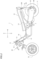
- FIG. 2 is a left side view of a part of the leaning vehicle 1.
- FIG. 3 is a left side view of a part of the leaning vehicle 1.
- FIG. 4 is a front view of a part of the leaning vehicle 1.
- FIG. 5 is a plan view of a part of the leaning vehicle 1.
- front, rear, left, right, up and down refer to these directions as seen from a virtual rider seated on a seat 5 while the leaning vehicle 1 is standing upright (standing upright as used herein refers to a state where a vehicle body frame 10 to be described below is standing upright) on a horizontal surface with no rider and no load thereon, unless specified otherwise.
- the vehicle up-down direction coincides with the vertical direction.
- the vehicle front-rear direction is orthogonal to the vehicle up-down direction.
- the vehicle left-right direction is orthogonal to the vehicle front-rear direction and the vehicle up-down direction.
- the leaning vehicle 1 includes the vehicle body frame 10, a link mechanism 20, a left front wheel 3L, a right front wheel 3R (see FIG. 4 ), a rear wheel 4, a power unit 2, the seat 5 and a storage box 16.
- the leaning vehicle 1 is a three-wheel vehicle with two front wheels 3L, 3R and one rear wheel 4.
- the leaning vehicle 1 also includes a center stand 61 and a side stand 62.
- the vehicle body frame 10 includes a head pipe 11, a down frame 12 extending rearward and downward from the head pipe 11, and a seat frame 13 extending rearward from the down frame 12.
- the seat 5 is supported by the vehicle body frame 10.
- the seat 5 is supported by the seat frame 13.
- the storage box 16 is arranged downward of the seat 5, and supported by the seat frame 13.
- a steering shaft 14 is rotatably supported by the head pipe 11.
- a steering handle 15 is fixed to the steering shaft 14.
- An accelerator grip 15R is provided at the right end portion of the steering handle 15, and a left grip 15L is provided at the left end portion of the steering handle 15.
- the leaning vehicle 1 is a scooter.
- the leaning vehicle 1 includes a low footrest 7.
- the footrest 7 is supported by the vehicle body frame 10.
- the footrest 7 is supported by the down frame 12 (see FIG. 2 ).
- the footrest 7 is arranged downward of the seat 5.
- the footrest 7 is a platform for supporting the feet of the rider seated on the seat 5.
- the link mechanism 20 is a parallelogram link-type link mechanism.
- the link mechanism 20 is arranged upward relative to the left front wheel 3L and the right front wheel 3R.
- the link mechanism 20 includes an upper arm 21, a lower arm 22, a left arm 23 and a right arm 24.
- the upper arm 21 and the lower arm 22 extend leftward and rightward.
- the upper arm 21 and the lower arm 22 are examples of link members extending leftward and rightward of the vehicle body frame 10.
- the lower arm 22 is arranged downward of the upper arm 21.
- the upper arm 21 and the lower arm 22 are arranged forward of the head pipe 11 (see FIG. 2 ).
- the upper arm 21 is rotatably linked to the head pipe 11 by a first central link shaft 21Cc extending in the vehicle front-rear direction.
- the lower arm 22 is rotatably linked to the head pipe 11 by a second central link shaft 22Cc extending in the vehicle front-rear direction.
- another lower arm 22B is arranged rearward of the head pipe 11.
- the lower arm 22B extends leftward and rightward.
- the lower arm 22B is arranged downward of the upper arm 21.
- the lower arm 22B is rotatably linked to the head pipe 11 by a third central link shaft 23Cc (see FIG. 3 ) extending in the vehicle front-rear direction.
- another upper arm (not shown) may be arranged rearward of the head pipe 11, and this upper arm may be rotatably linked to the head pipe 11 by another central link shaft (not shown) extending in the vehicle front-rear direction.
- the other upper arm and the other lower arm 22B arranged rearward of the head pipe 11 are optional.
- the left arm 23 and the right arm 24 extend upward and downward.
- the left arm 23 is arranged leftward of the head pipe 11 and the right arm 24 is arranged rightward of the head pipe 11.
- the right arm 24 is arranged rightward of the left arm 23.
- the left arm 23 and the right arm 24 are arranged rearward of the upper arm 21 and the lower arm 22.
- the left arm 23 and the right arm 24 are arranged forward of the lower arm 22B.
- the left arm 23 and the right arm 24 are rotatably linked to the upper arm 21, the lower arm 22 and the lower arm 22B.
- the upper end portion of the left arm 23 is rotatably linked to the left end portion of the upper arm 21 by a first left link shaft 21 Lc extending in the vehicle front-rear direction.
- the lower end portion of the left arm 23 is rotatably linked to the left end portion of the lower arm 22 by a second left link shaft 22Lc extending in the vehicle front-rear direction.
- the lower end of the left arm 23 is rotatably linked to the left end portion of the lower arm 22B by a third left link shaft (not shown) extending in the vehicle front-rear direction.
- the upper end portion of the right arm 24 is rotatably linked to the right end portion of the upper arm 21 by the first right link shaft 21 Rc extending in the vehicle front-rear direction.
- the lower end portion of the right arm 24 is rotatably linked to the right end portion of the lower arm 22 by the second right link shaft 22Rc extending in the vehicle front-rear direction.
- the lower end portion of the right arm 24 is rotatably linked to the right end portion of the lower arm 22B by a third right link shaft (not shown) extending in the vehicle front-rear direction.
- the leaning vehicle 1 includes, as front suspensions, a left suspension 25L and a right suspension 25R.
- the left suspension 25L and the right suspension 25R are telescopic suspensions.
- the upper end portion of the left suspension 25L and the upper end portion of the right suspension 25R are connected to the link mechanism 20.
- the lower end portion of the left suspension 25L is connected to the left front wheel 3L, and the lower portion of the right suspension 25R is connected to the right front wheel 3R.
- the upper end portion of the left suspension 25L is connected to the lower end portion of the left arm 23 via a left bracket 26L.
- the upper end portion of the left suspension 25L is connected to the left arm 23 so as to be rotatable in the left-right direction of the vehicle body frame 10.
- the upper end portion of the right suspension 25R is connected to the lower end portion of the right arm 24 via a right bracket 26R.
- the upper end portion of the right suspension 25R is connected to the right arm 24 so as to be rotatable in the left-right direction of the vehicle body frame 10.
- the left suspension 25L, the left bracket 26L and the left arm 23 together form a left wheel support member 19L that supports the left front wheel 3L.
- the right suspension 25R, the right bracket 26R and the right arm 24 together form a right wheel support member 19R that supports the right front wheel 3R.
- a center plate 27C is fixed to the lower end portion of the steering shaft 14. As shown in FIG. 5 , the center plate 27C extends forward from the steering shaft 14. A left plate 27L is fixed to the left bracket 26L. A right plate 27R is fixed to the right bracket 26R. The left plate 27L, the center plate 27C and the right plate 27R are linked to a tie rod 28 so as to be rotatable left and right.
- the steering shaft 14 is linked to the left arm 23 and the right arm 24 via the center plate 27C, the tie rods 28, the left plate 27L and the right plate 27R.
- the leaning vehicle 1 includes a roll angle control device 30 that controls the roll angle.
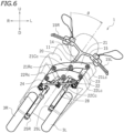
- the roll angle as used herein is the tilt angle ⁇ (see FIG. 6 ) of the vehicle body frame 10 from the vertical line.
- the roll angle ⁇ is equal to the angle between the axis of the head pipe 11 and the vertical line as viewed in the vehicle front view.
- the roll angle control device 30 controls the roll angle of the vehicle body frame 10 by adjusting the rotation of the upper arm 21 and the lower arm 22 relative to the vehicle body frame 10.
- the roll angle control device 30 is configured to apply a torque to at least one of the upper arm 21 and the lower arm 22.
- the roll angle control device 30 is connected to at least one of the upper arm 21 and lower arm 22, and to the vehicle body frame 10. In the present embodiment, the roll angle control device 30 is connected to the upper arm 21 and the head pipe 11. Note however that there is no particular limitation thereto, and the roll angle control device 30 may be connected to the lower arm 22 and the head pipe 11.
- the roll angle control device 30 includes a case 31, a lean actuator 33, a gear 35A and a gear 35B arranged inside the case 31, and an actuator control device 36 arranged inside the case 31.
- the case 31 is supported by a support member 32 fixed to the head pipe 11.
- the lean actuator 33 is a power source that applies a torque around the first central link shaft 21Cc to the vehicle body frame 10.
- the lean actuator 33 may apply a torque directly or indirectly to the vehicle body frame 10.
- the lean actuator 33 applies a leftward or rightward torque to the upper arm 21, thereby indirectly applying a rightward or leftward torque to the vehicle body frame 10.
- the lean actuator 33 is an electric motor. Note however that the lean actuator 33 is not limited to an electric motor as long as the lean actuator 33 can generate power.
- the lean actuator 33 is connected to the gear 35A, and the gear 35A is meshed with the gear 35B.
- the gear 35A and the gear 35B together form a decelerator.
- the gear 35B is fixed to an output shaft 34.
- the output shaft 34 is a rotating shaft driven by the lean actuator 33 and is connected to the upper arm 21.
- the torque of the lean actuator 33 is transmitted to the upper arm 21 via the gear 35A, the gear 35B and the output shaft 34.
- a torque around the first central link shaft 21Cc (see FIG. 4 ) is applied to the upper arm 21.
- the upper arm 21 is linked to the vehicle body frame 10 so as to be rotatable around the first central link shaft 21Cc, when a torque around the first central link shaft 21Cc is applied to the upper arm 21, a torque around the first central link shaft 21Cc is generated in the vehicle body frame 10.
- the leaning vehicle 1 includes an IMU (not shown).
- the actuator control device 36 is communicatively connected to the IMU via a wire harness (not shown).
- the actuator control device 36 is configured to receive a signal from the IMU and control the lean actuator 33.
- a power unit 2 is pivotally supported on the vehicle body frame 10.
- the power unit 2 is connected to the rear wheel 4 so that power can be transmitted therebetween.
- the power unit 2 generates driving force for traveling.
- the power unit 2 provides power to the rear wheel 4.
- the power unit 2 may include an internal combustion engine or may include an electric motor.
- the power unit 2 includes an internal combustion engine (hereinafter referred to as an "engine").
- the leaning vehicle 1 includes left and right rear suspensions 50.
- the left rear suspension 50 is arranged leftward of the rear wheel 4 and the right rear suspension 50 is arranged rightward of the rear wheel 4.
- Each rear suspension 50 includes an upper support portion 51 pivotably supported on the vehicle body frame 10 and a lower support portion 52 pivotably supported on the rear wheel 4.
- the upper support portion 51 is pivotably supported on the seat frame 13 via a bracket 13B.
- the lower support portion 52 is pivotably supported on a bracket 4B mounted on the axle of the rear wheel 4.
- the center stand 61 is a stand that supports the vehicle body frame 10 standing upright relative to the ground.
- the center stand 61 is configured to support the vehicle body frame 10 with the rear wheel 4 raised off the ground.
- the center stand 61 is mounted directly or indirectly on the vehicle body frame 10. Note that indirectly mounted means that it is mounted via another member such as a bracket.
- the center stand 61 is configured to be rotatable around the stand pivot 61c.
- the center stand 61 can change position between a retracted position and a support position by rotating around the stand pivot 61c.
- the support position of the center stand 61 is the position where the center stand 61 supports the vehicle body frame 10, and is the position indicated by the solid line in FIG. 1 .
- the center stand 61 is positioned in the support position when the leaning vehicle 1 is parked by using the center stand 61.
- the retracted position of the center stand 61 is the position where the center stand 61 is not supporting the vehicle body frame 10, and is the position indicated by the two-dot chain line in FIG. 1 .
- the center stand 61 is positioned in the retracted position when the leaning vehicle 1 is running and when the leaning vehicle 1 is parked by using the side stand 62.
- the center stand 61 is operated by a rider's foot. The rider uses a foot to change the position of the center stand 61.
- the side stand 62 is a stand that supports the vehicle body frame 10 in a tilted state relative to the ground.
- the side stand 62 is mounted directly or indirectly on the vehicle body frame 10.
- the side stand 62 is configured to be rotatable around a stand pivot 62c.
- the side stand 62 can change position between a retracted position and a support position by rotating around the stand pivot 62c.
- the support position of the side stand 62 is the position where the side stand 62 supports the vehicle body frame 10, and is indicated by the two-dot chain line in FIG. 1 .
- the side stand 62 is positioned in the support position when the leaning vehicle 1 is parked by using the side stand 62.
- the retracted position of the side stand 62 is the position where the side stand 62 is not supporting the vehicle body frame 10, and is indicated by the solid line in FIG. 1 .
- the side stand 62 is positioned in the retracted position when the leaning vehicle 1 is running and when the leaning vehicle 1 is parked by using the center stand 61. Similar to the center stand 61, the side stand 62 is operated by a rider's foot. The rider uses a foot to change the position of the side stand 62.
- the leaning vehicle 1 includes a center stand switch 63 as a sensor to detect whether the center stand 61 is in the support position.
- the center stand switch 63 is attached to the center stand 61.
- the center stand switch 63 is configured to detect the position of the center stand 61 based on the rotational position of the stand pivot 61c.
- the center stand switch 63 is configured to be ON when the center stand 61 is in the support position and OFF when the center stand 61 is not in the support position.
- the leaning vehicle 1 includes a side stand switch 64 as a sensor to detect whether the side stand 62 is in the support position.
- the side stand switch 64 is mounted on the side stand 62.
- the side stand switch 64 is configured to detect the position of the side stand 62 based on the rotational position of the stand pivot 62c.
- the side stand switch 64 is configured to be ON when the side stand 62 is in the support position and OFF when the side stand 62 is not in the support position.
- the actuator control device 36 controls the lean actuator 33 to automatically keep the vehicle body frame 10 standing upright.
- standing assist keeping the vehicle body frame 10 standing by itself by the actuator control device 36 controlling the lean actuator 33 will be referred to as standing assist.
- the vehicle body frame 10 is subjected to a leftward force. As it is, the vehicle body frame 10 will tilt leftward.
- the actuator control device 36 detects the tilt of the vehicle body frame 10 based on the signal from the IMU. Upon detecting the tilt of the vehicle body frame 10, the actuator control device 36 controls the lean actuator 33 so as to eliminate the tilt. Specifically, the actuator control device 36 controls the lean actuator 33 so that the roll angle of the vehicle body frame 10 is zero.
- the actuator control device 36 controls the lean actuator 33 to apply a rightward torque to the vehicle body frame 10.
- the actuator control device 36 controls the lean actuator 33 to apply a leftward torque to the vehicle body frame 10 when the vehicle body frame 10 tilts rightward.
- the leaning vehicle 1 includes a power source 41 that supplies power, a main switch 40, an operation switch 43, and electrical components including the actuator control device 36.
- the leaning vehicle 1 includes a battery and a generator that generates electricity by the power of the power unit 2.
- the power source 41 is comprised of the battery and the generator.
- the main switch 40 is a switch that switches ON/OFF the power supply from the power source 41 to electrical components.
- the main switch 40 or the operation switch 43 may be mounted on the steering handle 15, for example.
- the main switch 40 or the operation switch 43 may be arranged rightward of the left grip 15L or arranged leftward of the accelerator grip 15R.
- the operation switch 43 is a switch that switches ON/OFF the standing assist.
- the vehicle body frame 10 is kept standing by itself even if the rider does not put their feet on the ground.
- the vehicle body frame 10 is kept standing by itself even if the rider places both feet on the footrest 7. If the operation switch 43 is turned ON while the main switch 40 is ON, the standing assist is started, and if the operation switch 43 is turned OFF while the main switch 40 is ON, the standing assist is terminated.
- the actuator control device 36 is a computer. As shown in FIG. 7 , the actuator control device 36 executes a computer program and as a result functions as a standing assist control section 37, a standing assist discontinuation section 38 and a standing assist resumption section 39.
- the actuator control device 36 is communicatively connected to the center stand switch 63, the side stand switch 64 and the lean actuator 33.
- the actuator control device 36 is configured to detect the position of the center stand 61 and the side stand 62 by receiving signals from the center stand switch 63 and the side stand switch 64.
- the standing assist control section 37 controls the lean actuator 33 so as to keep the vehicle body frame 10 standing by itself. In other words, the standing assist control section 37 controls the lean actuator 33 so that the vehicle body frame 10 stands in the vertical direction. The standing assist control section 37 executes the standing assist.
- the standing assist discontinuation section 38 discontinues the standing assist of the standing assist control section 37.
- the standing assist discontinuation section 38 is configured to gradually reduce the output torque of the lean actuator 33 when discontinuing the standing assist. Specifically, as shown in FIG. 9 , upon detecting that the center stand 61 is in the support position, the standing assist discontinuation section 38 is configured to gradually reduce the output torque T of the lean actuator 33 until a predetermined amount of time t0 elapses from the detection so that the output torque T is zero when the predetermined amount of time t0 has elapsed. Note that the horizontal axis t in FIG. 9 represents the time elapsed since the detection of the center stand 61 being in the support position, and the vertical axis T represents the output torque of the lean actuator 33.
- the standing assist discontinuation section 38 is configured to gradually reduce the output torque of the lean actuator 33 until a predetermined amount of time elapses from the detection so that the output torque of the lean actuator 33 is zero when the predetermined amount of time has elapsed.
- the standing assist resumption section 39 resumes the standing assist by the standing assist control section 37.
- the leaning vehicle 1 is configured as described above.
- the leaning vehicle 1 according to the present embodiment is capable of providing standing assist, and with the standing assist, the rider can stop the leaning vehicle 1 without placing their feet on the ground. Then, the rider may park the leaning vehicle 1 by using the center stand 61 or the side stand 62 while the standing assist is being provided.
- the leaning vehicle 1 is parked by using the center stand 61 on the ground G tilted leftward relative to the horizontal plane HP, for example.
- the vehicle body frame 10 will be tilted leftward from the vertical line.
- the lean actuator 33 applies a rightward torque T to the vehicle body frame 10 so as to keep the vehicle body frame 10 standing in the vertical direction.
- the support by the center stand 61 may become unstable.
- the leaning vehicle 1 is parked by using the side stand 62. Also in such a case, the vehicle body frame 10 will be tilted leftward from the vertical line.
- the standing assist control section 37 is providing standing assist, a rightward torque T is applied to the vehicle body frame 10. As a result, the support by the side stand 62 may become unstable.
- the rider if the rider terminates the standing assist before pulling down the center stand 61 or the side stand 62, it is possible to prevent the center stand 61 or the side stand 62 from hindering the support by the lean actuator 33.
- terminating the standing assist requires an operation of the operation switch 43.
- the rider can park the leaning vehicle 1 by the center stand 61 or the side stand 62 by an easier operation.
- the output torque of the lean actuator 33 may be immediately eliminated upon detecting that the center stand 61 or the side stand 62 has been pulled down, the output torque of the lean actuator 33 is gradually reduced until the predetermined amount of time t0 elapses in the present embodiment (see FIG. 9 ).
- the vehicle body frame 10 can be supported more stably by the center stand 61 or the side stand 62.
- the rider When the rider gets on the leaning vehicle 1 being parked and starts the leaning vehicle 1, the rider first retracts the center stand 61 or the side stand 62 and then operates the accelerator grip 15R to drive the leaning vehicle 1. If the standing assist is executed in this process, the rider can easily start the leaning vehicle 1. According to the present embodiment, when the center stand 61 or the side stand 62 is moved to the retracted position while the standing assist is discontinued, the standing assist is resumed. Thus, the leaning vehicle 1 is standing by itself before starting, and the rider can easily start the leaning vehicle 1.
- the leaning vehicle 1 in the embodiment described above is a scooter.
- the vehicle form of the leaning vehicle is not limited to a scooter.
- the leaning vehicle 1 includes both the center stand 61 and the side stand 62. However, the leaning vehicle 1 may include only one of the center stand 61 and the side stand 62.
- the standing assist is turned ON/OFF as the rider operates the operation switch 43 in the embodiment described above
- the standing assist performed by the actuator control device 36 may be automatically turned ON/OFF based on a predetermined condition.
- the actuator control device 36 includes the standing assist resumption section 39 in the embodiment described above, the standing assist resumption section 39 may be optional.
- the standing assist discontinuation section 38 gradually reduce the output torque of the lean actuator 33 until the predetermined amount of time t0 elapses if it is detected that the center stand 61 or the side stand 62 is in the support position in the embodiment described above, there is no particular limitation on how the output torque is reduced.
- the output torque of the lean actuator 33 may be immediately set to zero when it is detected that the center stand 61 or the side stand 62 is in the support position.
- the center stand switch 63 is used as a sensor that detects whether or not the center stand 61 is in the support position in the embodiment described above, the sensor that detects whether or not the center stand 61 is in the support position is not limited to the center stand switch 63. Similarly, the sensor that detects whether or not the side stand 62 is in the support position is not limited to the side stand switch 64.
- the center stand 61 and the side stand 62 will be collectively referred to simply as a stand.
- an angle sensor (a tilt angle sensor, an IMU, etc.) provided on a vehicle body may be used if, for example, there is a difference between the inclination of the vehicle body when the stand is used (when the stand is in the support position, e.g., when parked) and the inclination of the vehicle body when the stand is not used (when the stand is in the retracted position, e.g., just before driving). It is possible to detect whether or not the stand is in the support position based on the tilt angle of the vehicle body detected by the angle sensor.
- a position sensor that measures the distance between, or the positions of, a predetermined part of the vehicle body frame 10 and a predetermined part of the stand may be used to detect whether or not the stand is in the support position based on the distance or the positions. It is also possible to detect whether or not the stand is in the support position based on the use of a plurality of switches in the vehicle. For example, it is possible to detect whether or not the stand is in the support position based on a seat sensor, an accelerator position sensor, ON/OFF of a steering handle switch that switches vehicle auxiliary equipment systems, or ON/OFF of a smart key.
- a sensor that detects the rotational position of the stand may be used to detect whether or not the stand is in the support position based on the rotational position of the stand.
- the support position and the retracted position of the stand may be detected. Instead of directly detecting the support position, it is possible to determine that the stand is in the support position if it is detected that the stand is not in the retracted position, and to determine that the stand is not in the support position if it is detected that the stand is in the retracted position. From the viewpoint of preventing false detection, positions between the retracted position and the support position may be detected so as to determine that the stand is neither in the retracted position nor in the support position when those in-between positions are detected.
Landscapes
- Engineering & Computer Science (AREA)
- Mechanical Engineering (AREA)
- Automatic Cycles, And Cycles In General (AREA)
- Axle Suspensions And Sidecars For Cycles (AREA)
Applications Claiming Priority (1)
| Application Number | Priority Date | Filing Date | Title |
|---|---|---|---|
| JP2023067597A JP2024154021A (ja) | 2023-04-18 | 2023-04-18 | リーン車両 |
Publications (2)
| Publication Number | Publication Date |
|---|---|
| EP4450375A1 true EP4450375A1 (de) | 2024-10-23 |
| EP4450375B1 EP4450375B1 (de) | 2025-04-30 |
Family
ID=90366159
Family Applications (1)
| Application Number | Title | Priority Date | Filing Date |
|---|---|---|---|
| EP24164130.7A Active EP4450375B1 (de) | 2023-04-18 | 2024-03-18 | Neigefahrzeug |
Country Status (3)
| Country | Link |
|---|---|
| EP (1) | EP4450375B1 (de) |
| JP (1) | JP2024154021A (de) |
| TW (1) | TWI899728B (de) |
Citations (3)
| Publication number | Priority date | Publication date | Assignee | Title |
|---|---|---|---|---|
| JP2018149962A (ja) | 2017-03-14 | 2018-09-27 | ヤマハ発動機株式会社 | リーン車両及びロール角制御方法 |
| EP4005902A1 (de) * | 2019-09-02 | 2022-06-01 | Yamaha Hatsudoki Kabushiki Kaisha | Neigefahrzeug |
| EP4159607A1 (de) * | 2021-09-30 | 2023-04-05 | Yamaha Hatsudoki Kabushiki Kaisha | Lean-steuervorrichtung und neigefahrzeug |
Family Cites Families (4)
| Publication number | Priority date | Publication date | Assignee | Title |
|---|---|---|---|---|
| EP3002202B1 (de) * | 2013-07-01 | 2018-04-04 | Yamaha Hatsudoki Kabushiki Kaisha | Fahrzeug |
| ITUB20152605A1 (it) * | 2015-07-29 | 2017-01-29 | Piaggio & C Spa | Avantreno di motoveicolo tiltante e relativo motoveicolo |
| JP2020075518A (ja) * | 2017-03-14 | 2020-05-21 | ヤマハ発動機株式会社 | 前二輪逆操舵リーン車両 |
| TWI829313B (zh) * | 2021-09-30 | 2024-01-11 | 日商山葉發動機股份有限公司 | 傾斜車輛 |
-
2023
- 2023-04-18 JP JP2023067597A patent/JP2024154021A/ja active Pending
- 2023-12-01 TW TW112146848A patent/TWI899728B/zh active
-
2024
- 2024-03-18 EP EP24164130.7A patent/EP4450375B1/de active Active
Patent Citations (3)
| Publication number | Priority date | Publication date | Assignee | Title |
|---|---|---|---|---|
| JP2018149962A (ja) | 2017-03-14 | 2018-09-27 | ヤマハ発動機株式会社 | リーン車両及びロール角制御方法 |
| EP4005902A1 (de) * | 2019-09-02 | 2022-06-01 | Yamaha Hatsudoki Kabushiki Kaisha | Neigefahrzeug |
| EP4159607A1 (de) * | 2021-09-30 | 2023-04-05 | Yamaha Hatsudoki Kabushiki Kaisha | Lean-steuervorrichtung und neigefahrzeug |
Also Published As
| Publication number | Publication date |
|---|---|
| TW202442513A (zh) | 2024-11-01 |
| TWI899728B (zh) | 2025-10-01 |
| EP4450375B1 (de) | 2025-04-30 |
| JP2024154021A (ja) | 2024-10-30 |
Similar Documents
| Publication | Publication Date | Title |
|---|---|---|
| US7975786B2 (en) | Electric ground working vehicle | |
| EP2213563B1 (de) | Koaxialzweiradfahrzeug und steuerverfahren dafür | |
| JP2010247723A (ja) | 走行装置及びその制御方法 | |
| JP2011046287A (ja) | 同軸二輪車及びその制御方法 | |
| JP2022514462A (ja) | 傾斜車両 | |
| JP4894589B2 (ja) | 車両 | |
| EP4450375B1 (de) | Neigefahrzeug | |
| EP4428024B1 (de) | Neigefahrzeug | |
| JP3812686B2 (ja) | 電動車両の駆動力制御装置 | |
| EP4414255B1 (de) | Neigefahrzeug | |
| JP3850066B2 (ja) | 電動車両の駆動力制御装置 | |
| JP5157722B2 (ja) | 同軸二輪車及びその制御方法 | |
| JP2010030440A (ja) | 同軸二輪車及びその制御方法 | |
| JPH0546679U (ja) | 作業車 | |
| JP3140008B2 (ja) | 油圧駆動式フォークリフト | |
| JP3886114B2 (ja) | 作業用車両のエンジン制御装置 | |
| JP2004010292A (ja) | 作業用車両の安全装置 | |
| JP2022095323A (ja) | 作業車両 | |
| JP2585432Y2 (ja) | 走行車輌 | |
| JP2002068684A (ja) | 高所作業車 | |
| JPH0622163U (ja) | 作業車 | |
| JPH05265542A (ja) | 自動操向作業車 | |
| JP2003252225A (ja) | 荷役車両のステアリング制御装置 | |
| JP2009018754A (ja) | 搬送車におけるリトラクタブル装置 |
Legal Events
| Date | Code | Title | Description |
|---|---|---|---|
| PUAI | Public reference made under article 153(3) epc to a published international application that has entered the european phase |
Free format text: ORIGINAL CODE: 0009012 |
|
| STAA | Information on the status of an ep patent application or granted ep patent |
Free format text: STATUS: THE APPLICATION HAS BEEN PUBLISHED |
|
| AK | Designated contracting states |
Kind code of ref document: A1 Designated state(s): AL AT BE BG CH CY CZ DE DK EE ES FI FR GB GR HR HU IE IS IT LI LT LU LV MC ME MK MT NL NO PL PT RO RS SE SI SK SM TR |
|
| STAA | Information on the status of an ep patent application or granted ep patent |
Free format text: STATUS: REQUEST FOR EXAMINATION WAS MADE |
|
| 17P | Request for examination filed |
Effective date: 20241119 |
|
| RBV | Designated contracting states (corrected) |
Designated state(s): AL AT BE BG CH CY CZ DE DK EE ES FI FR GB GR HR HU IE IS IT LI LT LU LV MC ME MK MT NL NO PL PT RO RS SE SI SK SM TR |
|
| P01 | Opt-out of the competence of the unified patent court (upc) registered |
Free format text: CASE NUMBER: APP_64552/2024 Effective date: 20241205 |
|
| GRAP | Despatch of communication of intention to grant a patent |
Free format text: ORIGINAL CODE: EPIDOSNIGR1 |
|
| STAA | Information on the status of an ep patent application or granted ep patent |
Free format text: STATUS: GRANT OF PATENT IS INTENDED |
|
| RIC1 | Information provided on ipc code assigned before grant |
Ipc: B62K 5/08 20060101ALI20250108BHEP Ipc: B62K 5/05 20130101ALI20250108BHEP Ipc: B62K 5/027 20130101ALI20250108BHEP Ipc: B62H 1/04 20060101ALI20250108BHEP Ipc: B62H 1/02 20060101ALI20250108BHEP Ipc: B62K 5/10 20130101AFI20250108BHEP |
|
| INTG | Intention to grant announced |
Effective date: 20250131 |
|
| GRAS | Grant fee paid |
Free format text: ORIGINAL CODE: EPIDOSNIGR3 |
|
| GRAA | (expected) grant |
Free format text: ORIGINAL CODE: 0009210 |
|
| STAA | Information on the status of an ep patent application or granted ep patent |
Free format text: STATUS: THE PATENT HAS BEEN GRANTED |
|
| AK | Designated contracting states |
Kind code of ref document: B1 Designated state(s): AL AT BE BG CH CY CZ DE DK EE ES FI FR GB GR HR HU IE IS IT LI LT LU LV MC ME MK MT NL NO PL PT RO RS SE SI SK SM TR |
|
| REG | Reference to a national code |
Ref country code: CH Ref legal event code: EP Ref country code: GB Ref legal event code: FG4D |
|
| REG | Reference to a national code |
Ref country code: DE Ref legal event code: R096 Ref document number: 602024000091 Country of ref document: DE |
|
| REG | Reference to a national code |
Ref country code: IE Ref legal event code: FG4D |
|
| REG | Reference to a national code |
Ref country code: NL Ref legal event code: MP Effective date: 20250430 |
|
| REG | Reference to a national code |
Ref country code: AT Ref legal event code: MK05 Ref document number: 1789823 Country of ref document: AT Kind code of ref document: T Effective date: 20250430 |
|
| PG25 | Lapsed in a contracting state [announced via postgrant information from national office to epo] |
Ref country code: FI Free format text: LAPSE BECAUSE OF FAILURE TO SUBMIT A TRANSLATION OF THE DESCRIPTION OR TO PAY THE FEE WITHIN THE PRESCRIBED TIME-LIMIT Effective date: 20250430 Ref country code: PT Free format text: LAPSE BECAUSE OF FAILURE TO SUBMIT A TRANSLATION OF THE DESCRIPTION OR TO PAY THE FEE WITHIN THE PRESCRIBED TIME-LIMIT Effective date: 20250901 Ref country code: ES Free format text: LAPSE BECAUSE OF FAILURE TO SUBMIT A TRANSLATION OF THE DESCRIPTION OR TO PAY THE FEE WITHIN THE PRESCRIBED TIME-LIMIT Effective date: 20250430 |
|
| REG | Reference to a national code |
Ref country code: LT Ref legal event code: MG9D |
|
| PG25 | Lapsed in a contracting state [announced via postgrant information from national office to epo] |
Ref country code: GR Free format text: LAPSE BECAUSE OF FAILURE TO SUBMIT A TRANSLATION OF THE DESCRIPTION OR TO PAY THE FEE WITHIN THE PRESCRIBED TIME-LIMIT Effective date: 20250731 Ref country code: NO Free format text: LAPSE BECAUSE OF FAILURE TO SUBMIT A TRANSLATION OF THE DESCRIPTION OR TO PAY THE FEE WITHIN THE PRESCRIBED TIME-LIMIT Effective date: 20250730 |
|
| PG25 | Lapsed in a contracting state [announced via postgrant information from national office to epo] |
Ref country code: PL Free format text: LAPSE BECAUSE OF FAILURE TO SUBMIT A TRANSLATION OF THE DESCRIPTION OR TO PAY THE FEE WITHIN THE PRESCRIBED TIME-LIMIT Effective date: 20250430 Ref country code: NL Free format text: LAPSE BECAUSE OF FAILURE TO SUBMIT A TRANSLATION OF THE DESCRIPTION OR TO PAY THE FEE WITHIN THE PRESCRIBED TIME-LIMIT Effective date: 20250430 |
|
| PG25 | Lapsed in a contracting state [announced via postgrant information from national office to epo] |
Ref country code: BG Free format text: LAPSE BECAUSE OF FAILURE TO SUBMIT A TRANSLATION OF THE DESCRIPTION OR TO PAY THE FEE WITHIN THE PRESCRIBED TIME-LIMIT Effective date: 20250430 |
|
| PG25 | Lapsed in a contracting state [announced via postgrant information from national office to epo] |
Ref country code: HR Free format text: LAPSE BECAUSE OF FAILURE TO SUBMIT A TRANSLATION OF THE DESCRIPTION OR TO PAY THE FEE WITHIN THE PRESCRIBED TIME-LIMIT Effective date: 20250430 |
|
| PG25 | Lapsed in a contracting state [announced via postgrant information from national office to epo] |
Ref country code: AT Free format text: LAPSE BECAUSE OF FAILURE TO SUBMIT A TRANSLATION OF THE DESCRIPTION OR TO PAY THE FEE WITHIN THE PRESCRIBED TIME-LIMIT Effective date: 20250430 |
|
| PG25 | Lapsed in a contracting state [announced via postgrant information from national office to epo] |
Ref country code: RS Free format text: LAPSE BECAUSE OF FAILURE TO SUBMIT A TRANSLATION OF THE DESCRIPTION OR TO PAY THE FEE WITHIN THE PRESCRIBED TIME-LIMIT Effective date: 20250731 |
|
| PG25 | Lapsed in a contracting state [announced via postgrant information from national office to epo] |
Ref country code: IS Free format text: LAPSE BECAUSE OF FAILURE TO SUBMIT A TRANSLATION OF THE DESCRIPTION OR TO PAY THE FEE WITHIN THE PRESCRIBED TIME-LIMIT Effective date: 20250830 |
|
| PG25 | Lapsed in a contracting state [announced via postgrant information from national office to epo] |
Ref country code: LV Free format text: LAPSE BECAUSE OF FAILURE TO SUBMIT A TRANSLATION OF THE DESCRIPTION OR TO PAY THE FEE WITHIN THE PRESCRIBED TIME-LIMIT Effective date: 20250430 |
|
| PG25 | Lapsed in a contracting state [announced via postgrant information from national office to epo] |
Ref country code: DK Free format text: LAPSE BECAUSE OF FAILURE TO SUBMIT A TRANSLATION OF THE DESCRIPTION OR TO PAY THE FEE WITHIN THE PRESCRIBED TIME-LIMIT Effective date: 20250430 Ref country code: SM Free format text: LAPSE BECAUSE OF FAILURE TO SUBMIT A TRANSLATION OF THE DESCRIPTION OR TO PAY THE FEE WITHIN THE PRESCRIBED TIME-LIMIT Effective date: 20250430 |
|
| PG25 | Lapsed in a contracting state [announced via postgrant information from national office to epo] |
Ref country code: CZ Free format text: LAPSE BECAUSE OF FAILURE TO SUBMIT A TRANSLATION OF THE DESCRIPTION OR TO PAY THE FEE WITHIN THE PRESCRIBED TIME-LIMIT Effective date: 20250430 |
|
| PG25 | Lapsed in a contracting state [announced via postgrant information from national office to epo] |
Ref country code: EE Free format text: LAPSE BECAUSE OF FAILURE TO SUBMIT A TRANSLATION OF THE DESCRIPTION OR TO PAY THE FEE WITHIN THE PRESCRIBED TIME-LIMIT Effective date: 20250430 |
|
| PG25 | Lapsed in a contracting state [announced via postgrant information from national office to epo] |
Ref country code: SK Free format text: LAPSE BECAUSE OF FAILURE TO SUBMIT A TRANSLATION OF THE DESCRIPTION OR TO PAY THE FEE WITHIN THE PRESCRIBED TIME-LIMIT Effective date: 20250430 |
|
| REG | Reference to a national code |
Ref country code: DE Ref legal event code: R097 Ref document number: 602024000091 Country of ref document: DE |
|
| PLBE | No opposition filed within time limit |
Free format text: ORIGINAL CODE: 0009261 |
|
| STAA | Information on the status of an ep patent application or granted ep patent |
Free format text: STATUS: NO OPPOSITION FILED WITHIN TIME LIMIT |
|
| REG | Reference to a national code |
Ref country code: CH Ref legal event code: L10 Free format text: ST27 STATUS EVENT CODE: U-0-0-L10-L00 (AS PROVIDED BY THE NATIONAL OFFICE) Effective date: 20260311 |
|
| 26N | No opposition filed |
Effective date: 20260202 |
|
| PGFP | Annual fee paid to national office [announced via postgrant information from national office to epo] |
Ref country code: DE Payment date: 20260319 Year of fee payment: 3 |
|
| PGFP | Annual fee paid to national office [announced via postgrant information from national office to epo] |
Ref country code: FR Payment date: 20260323 Year of fee payment: 3 |