EP4428024B1 - Neigefahrzeug - Google Patents
Neigefahrzeug Download PDFInfo
- Publication number
- EP4428024B1 EP4428024B1 EP24156292.5A EP24156292A EP4428024B1 EP 4428024 B1 EP4428024 B1 EP 4428024B1 EP 24156292 A EP24156292 A EP 24156292A EP 4428024 B1 EP4428024 B1 EP 4428024B1
- Authority
- EP
- European Patent Office
- Prior art keywords
- vehicle
- body frame
- actuator
- vehicle body
- rider
- Prior art date
- Legal status (The legal status is an assumption and is not a legal conclusion. Google has not performed a legal analysis and makes no representation as to the accuracy of the status listed.)
- Active
Links
Images


Classifications
-
- B—PERFORMING OPERATIONS; TRANSPORTING
- B62—LAND VEHICLES FOR TRAVELLING OTHERWISE THAN ON RAILS
- B62K—CYCLES; CYCLE FRAMES; CYCLE STEERING DEVICES; RIDER-OPERATED TERMINAL CONTROLS SPECIALLY ADAPTED FOR CYCLES; CYCLE AXLE SUSPENSIONS; CYCLE SIDECARS, FORECARS, OR THE LIKE
- B62K5/00—Cycles with handlebars, equipped with three or more main road wheels
- B62K5/08—Cycles with handlebars, equipped with three or more main road wheels with steering devices acting on two or more wheels
-
- B—PERFORMING OPERATIONS; TRANSPORTING
- B62—LAND VEHICLES FOR TRAVELLING OTHERWISE THAN ON RAILS
- B62K—CYCLES; CYCLE FRAMES; CYCLE STEERING DEVICES; RIDER-OPERATED TERMINAL CONTROLS SPECIALLY ADAPTED FOR CYCLES; CYCLE AXLE SUSPENSIONS; CYCLE SIDECARS, FORECARS, OR THE LIKE
- B62K5/00—Cycles with handlebars, equipped with three or more main road wheels
- B62K5/10—Cycles with handlebars, equipped with three or more main road wheels with means for inwardly inclining the vehicle body on bends
-
- B—PERFORMING OPERATIONS; TRANSPORTING
- B62—LAND VEHICLES FOR TRAVELLING OTHERWISE THAN ON RAILS
- B62K—CYCLES; CYCLE FRAMES; CYCLE STEERING DEVICES; RIDER-OPERATED TERMINAL CONTROLS SPECIALLY ADAPTED FOR CYCLES; CYCLE AXLE SUSPENSIONS; CYCLE SIDECARS, FORECARS, OR THE LIKE
- B62K5/00—Cycles with handlebars, equipped with three or more main road wheels
- B62K5/02—Tricycles
- B62K5/027—Motorcycles with three wheels
-
- B—PERFORMING OPERATIONS; TRANSPORTING
- B62—LAND VEHICLES FOR TRAVELLING OTHERWISE THAN ON RAILS
- B62K—CYCLES; CYCLE FRAMES; CYCLE STEERING DEVICES; RIDER-OPERATED TERMINAL CONTROLS SPECIALLY ADAPTED FOR CYCLES; CYCLE AXLE SUSPENSIONS; CYCLE SIDECARS, FORECARS, OR THE LIKE
- B62K5/00—Cycles with handlebars, equipped with three or more main road wheels
- B62K5/02—Tricycles
- B62K5/05—Tricycles characterised by a single rear wheel
Definitions
- the present invention relates to a leaning vehicle having a left wheel and a right wheel, wherein the leaning vehicle tilts when turning left and right.
- a leaning vehicle has been known in the art that includes a vehicle body frame capable of tilting when turning left and right, a left wheel and a right wheel supporting the vehicle body frame, and a link mechanism that links together the vehicle body frame, the left wheel and the right wheel.
- the vehicle body frame, the left wheel and the right wheel are linked to the link mechanism so that they are rotatable around an axis extending in the vehicle front-rear direction.
- WO 2011/161856 A1 discloses all of the features of the preamble of claim 1.
- the leaning vehicle includes an actuator that applies a torque around an axis extending in the vehicle front-rear direction to the vehicle body frame.
- the actuator can be controlled to keep the vehicle body frame standing by itself.
- standing assist keeping the vehicle body frame standing by itself by using the actuator will be referred to as standing assist.
- the rider may push the leaning vehicle to a parking location, for example, after the main switch is turned OFF.
- the vehicle body frame may be tilted to turn the leaning vehicle.
- the actuator continues to generate torque, it becomes difficult to turn the leaning vehicle while pushing it, and it is no longer possible to smoothly move the leaning vehicle.
- the present invention has been made in view of the above, and an object thereof is to provide a leaning vehicle, with which standing assist can be provided, there is little burden on the rider after the main switch is turned OFF, and it is easy for the rider to move the leaning vehicle.
- said object is solved by a leaning vehicle having the features of the independent claim 1. Preferred embodiments are laid down in the dependent claims.
- a leaning vehicle disclosed herein includes: a vehicle body frame including a head pipe; a left wheel arranged leftward relative to the head pipe; a right wheel arranged rightward relative to the head pipe; a left wheel support member that is configured to support the left wheel; a right wheel support member that is arranged rightward of the left wheel support member and is configured to support the right wheel; a link member extending leftward and rightward of the vehicle body frame; a central link shaft extending in a vehicle front-rear direction that rotatably links the vehicle body frame to the link member; a left link shaft extending in the vehicle front-rear direction that rotatably links the left wheel support member to the link member; a right link shaft extending in the vehicle front-rear direction that rotatably links the right wheel support member to the link member; an actuator that is configured to apply a torque around the central link shaft to the vehicle body frame; a control device that is configured to control the actuator; and a main switch that is operated by a rider.
- the control device includes: a standing assist control section that is configured to execute standing assist for keeping the vehicle body frame standing by itself by controlling the actuator; and a standing assist continuation section that is configured to continue the control of the actuator until a predetermined amount of time elapses when the main switch is turned OFF during execution of the standing assist, and that is configured to terminate the control of the actuator when the predetermined amount of time elapses.
- the torque of the actuator does not disappear immediately but remains until the predetermined amount of time elapses. Therefore, the rider does not need to support the vehicle body frame from the moment the main switch is turned OFF. Thus, it is possible to reduce the burden on the rider.
- the rider since the torque of the actuator disappears when the predetermined amount of time elapses after the main switch is turned OFF, the rider can turn the leaning vehicle while pushing the leaning vehicle. Thus, the rider can easily move the leaning vehicle to a parking location, etc., after the predetermined amount of time elapses.
- the standing assist continuation section may be configured to gradually decrease the torque output by the actuator until the predetermined amount of time elapses when the main switch is turned OFF during execution of the standing assist.
- the leaning vehicle may include a notification device that is configured to give a notification to the rider until the predetermined amount of time elapses when the main switch is turned OFF during execution of the standing assist.
- the rider can easily know that the torque of the actuator remains after the main switch is turned OFF.
- the rider can prepare for the disappearance of the torque of the actuator.
- the predetermined amount of time it may be 0.3 to 1 second, for example.
- the leaning vehicle may include: a steering shaft supported by the head pipe; and a steering handle fixed to the steering shaft.
- the left wheel and the right wheel may be a left front wheel and a right front wheel, respectively, arranged forward of the steering handle.
- the leaning vehicle may include: a seat supported by the vehicle body frame; and a footrest supported by the vehicle body frame, arranged downward of the seat, and supporting feet of the rider seated on the seat.
- the present invention it is possible to provide a leaning vehicle, with which standing assist can be provided, there is little burden on the rider after the main switch is turned OFF, and it is easy for the rider to move the leaning vehicle.
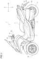
- FIG. 1 is a left side view of a leaning vehicle 1 according to the present embodiment.
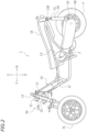
- FIG. 2 is a left side view of a part of the leaning vehicle 1.
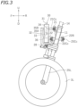
- FIG. 3 is a left side view of a part of the leaning vehicle 1.
- FIG. 4 is a front view of a part of the leaning vehicle 1.
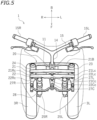
- FIG. 5 is a plan view of a part of the leaning vehicle 1.
- front, rear, left, right, up and down refer to these directions as seen from a virtual rider seated on a seat 5 while the leaning vehicle 1 is standing upright (standing upright as used herein refers to a state where a vehicle body frame 10 to be described below is standing upright) on a horizontal surface with no rider and no load thereon, unless specified otherwise.
- the vehicle up-down direction coincides with the vertical direction.
- the vehicle front-rear direction is orthogonal to the vehicle up-down direction.
- the vehicle left-right direction is orthogonal to the vehicle front-rear direction and the vehicle up-down direction.
- the leaning vehicle 1 includes the vehicle body frame 10, a link mechanism 20, a left front wheel 3L, a right front wheel 3R (see FIG. 4 ), a rear wheel 4, a power unit 2, the seat 5 and a storage box 16.
- the leaning vehicle 1 is a three-wheel vehicle with two front wheels 3L, 3R and one rear wheel 4.
- the vehicle body frame 10 includes a head pipe 11, a down frame 12 extending rearward and downward from the head pipe 11, and a seat frame 13 extending rearward from the down frame 12.
- the seat 5 is supported by the vehicle body frame 10.
- the seat 5 is supported by the seat frame 13.
- the storage box 16 is arranged downward of the seat 5, and supported by the seat frame 13.
- a steering shaft 14 is rotatably supported by the head pipe 11.
- a steering handle 15 is fixed to the steering shaft 14.
- the leaning vehicle 1 is a scooter.
- the leaning vehicle 1 includes a low footrest 7.
- the footrest 7 is supported by the vehicle body frame 10.
- the footrest 7 is supported by the down frame 12 (see FIG. 2 ).
- the footrest 7 is arranged downward of the seat 5.
- the footrest 7 is a platform for supporting the feet of the rider seated on the seat 5.
- the link mechanism 20 is a parallelogram link-type link mechanism.
- the link mechanism 20 is arranged upward relative to the left front wheel 3L and the right front wheel 3R.
- the link mechanism 20 includes an upper arm 21, a lower arm 22, a left arm 23 and a right arm 24.
- the upper arm 21 and the lower arm 22 extend leftward and rightward.
- the upper arm 21 and the lower arm 22 are examples of link members extending leftward and rightward of the vehicle body frame 10.
- the lower arm 22 is arranged downward of the upper arm 21.
- the upper arm 21 and the lower arm 22 are arranged forward of the head pipe 11 (see FIG. 2 ).
- the upper arm 21 is rotatably linked to the head pipe 11 by a first central link shaft 21Cc extending in the vehicle front-rear direction.
- the lower arm 22 is rotatably linked to the head pipe 11 by a second central link shaft 22Cc extending in the vehicle front-rear direction.
- another lower arm 22B is arranged rearward of the head pipe 11.
- the lower arm 22B extends leftward and rightward.
- the lower arm 22B is arranged downward of the upper arm 21.
- the lower arm 22B is rotatably linked to the head pipe 11 by a third central link shaft 23Cc (see FIG. 3 ) extending in the vehicle front-rear direction.
- another upper arm (not shown) may be arranged rearward of the head pipe 11, and this upper arm may be rotatably linked to the head pipe 11 by another central link shaft (not shown) extending in the vehicle front-rear direction.
- the other upper arm and the other lower arm 22B arranged rearward of the head pipe 11 are optional.
- the left arm 23 and the right arm 24 extend upward and downward.
- the left arm 23 is arranged leftward of the head pipe 11 and the right arm 24 is arranged rightward of the head pipe 11.
- the right arm 24 is arranged rightward of the left arm 23.
- the left arm 23 and the right arm 24 are arranged rearward of the upper arm 21 and the lower arm 22.
- the left arm 23 and the right arm 24 are arranged forward of the lower arm 22B.
- the left arm 23 and the right arm 24 are rotatably linked to the upper arm 21, the lower arm 22 and the lower arm 22B.
- the upper end portion of the left arm 23 is rotatably linked to the left end portion of the upper arm 21 by a first left link shaft 21Lc extending in the vehicle front-rear direction.
- the lower end portion of the left arm 23 is rotatably linked to the left end portion of the lower arm 22 by a second left link shaft 22Lc extending in the vehicle front-rear direction.
- the lower end of the left arm 23 is rotatably linked to the left end portion of the lower arm 22B by a third left link shaft (not shown) extending in the vehicle front-rear direction.
- the upper end portion of the right arm 24 is rotatably linked to the right end portion of the upper arm 21 by the first right link shaft 21Rc extending in the vehicle front-rear direction.
- the lower end portion of the right arm 24 is rotatably linked to the right end portion of the lower arm 22 by the second right link shaft 22Rc extending in the vehicle front-rear direction.
- the lower end portion of the right arm 24 is rotatably linked to the right end portion of the lower arm 22B by a third right link shaft (not shown) extending in the vehicle front-rear direction.
- the leaning vehicle 1 includes, as front suspensions, a left suspension 25L and a right suspension 25R.
- the left suspension 25L and the right suspension 25R are telescopic suspensions.
- the upper end portion of the left suspension 25L and the upper end portion of the right suspension 25R are connected to the link mechanism 20.
- the lower end portion of the left suspension 25L is connected to the left front wheel 3L, and the lower portion of the right suspension 25R is connected to the right front wheel 3R.
- the upper end portion of the left suspension 25L is connected to the lower end portion of the left arm 23 via a left bracket 26L.
- the upper end portion of the left suspension 25L is connected to the left arm 23 so as to be rotatable in the left-right direction of the vehicle body frame 10.
- the upper end portion of the right suspension 25R is connected to the lower end portion of the right arm 24 via a right bracket 26R.
- the upper end portion of the right suspension 25R is connected to the right arm 24 so as to be rotatable in the left-right direction of the vehicle body frame 10.
- the left suspension 25L, the left bracket 26L and the left arm 23 together form a left wheel support member 19L that supports the left front wheel 3L.
- the right suspension 25R, the right bracket 26R and the right arm 24 together form a right wheel support member 19R that supports the right front wheel 3R.
- a center plate 27C is fixed to the lower end portion of the steering shaft 14. As shown in FIG. 5 , the center plate 27C extends forward from the steering shaft 14. A left plate 27L is fixed to the left bracket 26L. A right plate 27R is fixed to the right bracket 26R. The left plate 27L, the center plate 27C and the right plate 27R are linked to a tie rod 28 so as to be rotatable left and right.
- the steering shaft 14 is linked to the left arm 23 and the right arm 24 via the center plate 27C, the tie rod 28, the left plate 27L and the right plate 27R.
- the leaning vehicle 1 includes a roll angle control device 30 that controls the roll angle.
- the roll angle as used herein is the tilt angle ⁇ (see FIG. 6 ) of the vehicle body frame 10 from the vertical line.
- the roll angle ⁇ is equal to the angle between the axis of the head pipe 11 and the vertical line as viewed in the vehicle front view.
- the roll angle control device 30 controls the roll angle of the vehicle body frame 10 by adjusting the rotation of the upper arm 21 and the lower arm 22 relative to the vehicle body frame 10.
- the roll angle control device 30 is configured to apply a torque to at least one of the upper arm 21 and the lower arm 22.
- the roll angle control device 30 is connected to at least one of the upper arm 21 and lower arm 22, and to the vehicle body frame 10. In the present embodiment, the roll angle control device 30 is connected to the upper arm 21 and the head pipe 11. Note however that there is no particular limitation thereto, and the roll angle control device 30 may be connected to the lower arm 22 and the head pipe 11.
- the roll angle control device 30 includes a case 31, a lean actuator 33, a gear 35A and a gear 35B arranged inside the case 31, and an actuator control device 36 arranged inside the case 31.
- the case 31 is supported by a support member 32 fixed to the head pipe 11.
- the lean actuator 33 is a power source that applies a torque around the first central link shaft 21Cc to the vehicle body frame 10.
- the lean actuator 33 may apply a torque directly or indirectly to the vehicle body frame 10.
- the lean actuator 33 applies a leftward or rightward torque to the upper arm 21, thereby indirectly applying a rightward or leftward torque to the vehicle body frame 10.
- the lean actuator 33 is an electric motor. Note however that the lean actuator 33 is not limited to an electric motor as long as the lean actuator 33 can generate power.
- the lean actuator 33 is connected to the gear 35A, and the gear 35A is meshed with the gear 35B.
- the gear 35A and the gear 35B together form a decelerator.
- the gear 35B is fixed to an output shaft 34.
- the output shaft 34 is a rotating shaft driven by the lean actuator 33 and is connected to the upper arm 21.
- the torque of the lean actuator 33 is transmitted to the upper arm 21 via the gear 35A, the gear 35B and the output shaft 34.
- a torque around the first central link shaft 21Cc (see FIG. 4 ) is applied to the upper arm 21.
- the upper arm 21 is linked to the vehicle body frame 10 so as to be rotatable around the first central link shaft 21Cc , when a torque around the first central link shaft 21Cc is applied to the upper arm 21, a torque around the first central link shaft 21Cc is generated in the vehicle body frame 10.
- the leaning vehicle 1 includes an IMU (not shown).
- the actuator control device 36 is communicatively connected to the IMU via a wire harness (not shown).
- the actuator control device 36 is configured to receive a signal from the IMU and control the lean actuator 33.
- a power unit 2 is pivotally supported on the vehicle body frame 10.
- the power unit 2 is connected to the rear wheel 4 so that power can be transmitted therebetween.
- the power unit 2 generates driving force for traveling.
- the power unit 2 provides power to the rear wheel 4.
- the power unit 2 may include an internal combustion engine or may include an electric motor.
- the power unit 2 includes an internal combustion engine (hereinafter referred to as an "engine").
- the leaning vehicle 1 includes left and right rear suspensions 50.
- the left rear suspension 50 is arranged leftward of the rear wheel 4 and the right rear suspension 50 is arranged rightward of the rear wheel 4.
- Each rear suspension 50 includes an upper support portion 51 pivotably supported on the vehicle body frame 10 and a lower support portion 52 pivotably supported on the rear wheel 4.
- the upper support portion 51 is pivotably supported on the seat frame 13 via a bracket 13B.
- the lower support portion 52 is pivotably supported on a bracket 4B mounted on the axle of the rear wheel 4.
- the leaning vehicle 1 includes a power source 41 that supplies power, a main switch 40 that is operated by the rider, an operation switch 43, and electrical components including an actuator control device 36.
- the leaning vehicle 1 includes a battery and a generator that generates electricity from the power of a power unit 2.
- the power source 41 is composed of the battery and the generator.
- the main switch 40 is a switch that switches ON/OFF the power supply from the power source 41 to electrical components.
- the main switch 40 or the operation switch 43 may be mounted on the steering handle 15, for example.
- the main switch 40 or the operation switch 43 may be arranged rightward of a left grip 15L or arranged leftward of a right grip 15R.
- the actuator control device 36 controls the lean actuator 33 to automatically keep the vehicle body frame 10 standing upright.
- the control by which the actuator control device 36 controls the lean actuator 33 keep the vehicle body frame 10 standing by itself will hereinafter be referred to as standing assist.
- the vehicle body frame 10 is subjected to a leftward force. As it is, the vehicle body frame 10 will lean leftward.
- the actuator control device 36 detects the tilt of the vehicle body frame 10 based on the signal from the IMU.
- the actuator control device 36 controls the lean actuator 33 to eliminate the tilt. Specifically, the actuator control device 36 controls the lean actuator 33 so that the roll angle of the vehicle body frame 10 becomes zero.
- the actuator control device 36 controls the lean actuator 33 so as to apply a rightward torque to the vehicle body frame 10.
- the actuator control device 36 controls the lean actuator 33 so as to apply a leftward torque to the vehicle body frame 10.
- the operation switch 43 is a switch that turns ON/OFF the standing assist.
- the vehicle body frame 10 is kept standing by itself even if the rider does not put their feet on the ground.
- the vehicle body frame 10 is kept standing by itself even if the rider places both feet on a footrest 7. If the operation switch 43 is turned ON while the main switch 40 is ON, the standing assist is started, and if the operation switch 43 is turned OFF while the main switch 40 is ON, the standing assist is terminated.
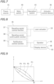
- the actuator control device 36 is a computer. As shown in FIG. 8 , the actuator control device 36 executes a computer program and as a result functions as a standing assist control section 37, a standing assist continuation section 38 and a notification control section 39.
- the standing assist control section 37 controls the lean actuator 33 so that the vehicle body frame 10 stands by itself when the operation switch 43 is ON.
- the standing assist continuation section 38 continues to control the lean actuator 33 until a predetermined amount of time (hereinafter referred to as the continuation time) elapses, and when the continuation time elapses, the control of the lean actuator 33 is terminated.
- the continuation time a predetermined amount of time (hereinafter referred to as the continuation time) elapses, and when the continuation time elapses, the control of the lean actuator 33 is terminated.
- the continuation time a predetermined amount of time
- the continuation time elapses
- the standing assist continuation section 38 may keep the output torque T of the lean actuator 33 constant until the continuation time t0 elapses after the main switch 40 is turned OFF, as indicated by a solid line P1 in FIG. 9 .
- the symbol t in FIG. 9 represents the elapsed time from when the main switch 40 is turned OFF
- the symbol T represents the output torque of the lean actuator 33.
- the standing assist continuation section 38 may gradually decrease the output torque T of the lean actuator 33 until the continuation time t0 elapses from when the main switch 40 is turned OFF, as indicated by a broken line P2, a single-dot chain line P3 or a double-dot chain line P4.
- the leaning vehicle 1 includes a speaker 45 and a display device 46.
- the notification control section 39 gives a notification to the rider until the continuation time elapses.
- the notification control section 39 outputs a sound from the speaker 45 and/or displays a predetermined image on the display device 46 until the continuation time elapses.
- the rider can easily know that the standing assist is continuing after the main switch 40 is turned OFF.
- the notification control section 39, the speaker 45 and the display device 46 together form a notification device 49.
- the leaning vehicle 1 is configured as described above. With the leaning vehicle 1 according to the present embodiment, the following effects can be obtained.
- the leaning vehicle 1 is capable of providing standing assist, and the leaning vehicle 1 can stand by itself even if the rider does not support the leaning vehicle 1 with their feet on the ground.
- the main switch 40 is turned OFF while the rider places their feet on the footrest 7
- the torque of the lean actuator 33 disappears suddenly and the vehicle body frame 10 tilts suddenly.
- the rider must quickly put their feet on the ground to support the vehicle body frame 10. This places a burden on the rider.
- the leaning vehicle 1 when the rider turns OFF the main switch 40 during execution of the standing assist, the torque of the lean actuator 33 does not disappear immediately, but remains until a predetermined continuation time elapses. Therefore, the rider does not need to support the vehicle body frame 10 from the moment the rider turns OFF the main switch 40. Between the time when the main switch 40 is turned OFF and the time when the torque of the lean actuator 33 disappears, there is a time margin for preparing to support the vehicle body frame 10. Therefore, with the leaning vehicle 1 according to the present embodiment, the burden on the rider after the main switch 40 is turned OFF can be reduced.
- the torque of the lean actuator 33 disappears after the continuation time elapses after the main switch 40 is turned OFF. Thereafter, the rider can turn the leaning vehicle 1 while pushing the leaning vehicle 1. Thus, the rider can easily move the leaning vehicle 1 to a parking location, etc., without having to perform a complicated operation.
- the standing assist continuation section 38 of the actuator control device 36 may gradually decrease the torque of the lean actuator 33 until the continuation time elapses when the main switch 40 is turned OFF during execution of the standing assist (see lines P2, P3 and P4 in FIG. 9 ).
- the torque of the lean actuator 33 it is possible to prevent the torque of the lean actuator 33 from disappearing rapidly before the continuation time elapses from when the rider turns OFF the main switch 40. This can prevent the load of the vehicle body frame 10 from being suddenly placed against the rider after the main switch 40 is turned OFF, thus reducing the burden on the rider.
- the notification device 49 is provided for giving a notification to the rider until the continuation time elapses when the main switch 40 is turned OFF during execution of the standing assist.
- the notification device 49 notifies the rider by means of a sound from the speaker 45 or an image by the display device 46.
- the rider can easily know that the torque of the lean actuator 33 remains and that the torque of the lean actuator 33 will eventually disappear.
- the rider can prepare for the disappearance of the torque of the lean actuator 33.
- the leaning vehicle 1 in the embodiment described above is a scooter.
- the vehicle form of the leaning vehicle is not limited to a scooter.
- the notification device 49 may include an additional device for giving a notification to the rider, other than the speaker 45 for giving a notification by means of a sound and the display device 46 for giving a notification by means of an image.
- the notification device 49 may be optional.
Landscapes
- Engineering & Computer Science (AREA)
- Mechanical Engineering (AREA)
- Automatic Cycles, And Cycles In General (AREA)
- Vehicle Body Suspensions (AREA)
Claims (6)
- Ein Neigefahrzeug (1), aufweisend:einen Fahrzeugkarosserierahmen (10) mit einem Steuerrohr (11);ein linkes Rad (3L), das relativ zum Steuerrohr (11) nach links angeordnet ist;ein rechtes Rad (3R), das relativ zum Steuerrohr (11) nach rechts angeordnet ist;ein linkes Radstützelement (19L), das so konfiguriert ist, dass es das linke Rad (3L) stützt;ein rechtes Radstützelement (19R), das rechts vom linken Radstützelement (19L) angeordnet ist und so konfiguriert ist, dass es das rechte Rad (3R) stützt;ein Verbindungselement (21), das sich links und rechts vom Fahrzeugkarosserierahmen (10) erstreckt;eine zentrale Verbindungswelle (21Cc), die sich in einer Richtung von vorne nach hinten des Fahrzeugs erstreckt und den Fahrzeugkarosserierahmen (10) drehbar mit dem Verbindungselement (21) verbindet;eine linke Verbindungswelle (21Lc), die sich in einer Richtung von vorne nach hinten des Fahrzeugs erstreckt und das linke Radstützelement (19L) drehbar mit dem Verbindungselement (21) verbindet;eine rechte Verbindungswelle (21Rc), die sich in der Richtung von vorne nach hinten des Fahrzeugs erstreckt und das rechte Radstützelement (19R) drehbar mit dem Verbindungselement (21) verbindet;einen Aktuator (33), der so konfiguriert ist, dass er ein Drehmoment um die zentrale Verbindungswelle (21Cc) auf den Fahrzeugkarosserierahmen (10) ausübt;eine Steuervorrichtung (36), die so konfiguriert ist, dass sie den Aktuator (33) steuert; undeinen Hauptschalter (40), der von einem Fahrer betätigt wird,wobei die Steuervorrichtung (36) aufweist:einen Stehhilfesteuerabschnitt (37), der so konfiguriert ist, dass er eine Stehhilfe ausführt, um den Fahrzeugkarosserierahmen (10) durch Steuern des Aktuators (33) von selbst aufrecht zu halten;dadurch gekennzeichnet, dass das Neigefahrzeugeinen Stehhilfefortsetzungsabschnitt (38) aufweist, der so konfiguriert ist, dass er die Steuerung des Aktuators (33) fortsetzt, bis eine vorbestimmte Zeitspanne verstrichen ist, wenn der Hauptschalter (40) während der Ausführung der Stehhilfe ausgeschaltet wird, und der so konfiguriert ist,dass er die Steuerung des Aktuators (33) beendet, wenn die vorbestimmte Zeitspanne verstrichen ist.
- Ein Neigefahrzeug (1) gemäß Anspruch 1, wobei der Stehhilfefortsetzungsabschnitt (38) so konfiguriert ist, dass er das vom Aktuator (33) abgegebene Drehmoment allmählich verringert, bis die vorgegebene Zeitspanne verstrichen ist, wenn der Hauptschalter (40) während der Ausführung der Stehhilfe ausgeschaltet wird.
- Ein Neigefahrzeug (1) nach Anspruch 1 oder 2, aufweisend eine Benachrichtigungsvorrichtung (49), die so konfiguriert ist, dass sie dem Fahrer eine Benachrichtigung gibt, bis die vorbestimmte Zeitspanne verstrichen ist, wenn der Hauptschalter (40) während der Ausführung der Stehhilfe ausgeschaltet wird.
- Ein Neigefahrzeug (1) gemäß einem der Ansprüche 1 bis 3, wobei die vorbestimmte Zeitdauer 0,3 bis 1 Sekunde beträgt.
- Ein Neigefahrzeug (1) gemäß einem der Ansprüche 1 bis 4, aufweisend:eine Lenkwelle (14), die von dem Steuerrohr (11) getragen wird; undeinen Lenkgriff (15), der an der Lenkwelle (14) befestigt ist,wobei das linke Rad (3L) und das rechte Rad (3R) ein linkes Vorderrad bzw. ein rechtes Vorderrad sind, die vor dem Lenkgriff (15) angeordnet sind.
- Ein Neigefahrzeug (1) gemäß einem der Ansprüche 1 bis 5, aufweisend:einen Sitz (5), der von dem Fahrzeugkarosserierahmen (10) getragen wird; undeine Fußstütze (7), die von dem Fahrzeugkarosserierahmen (10) getragen wird, unterhalb des Sitzes (5) angeordnet ist und die Füße des auf dem Sitz (5) sitzenden Fahrers stützt.
Applications Claiming Priority (1)
| Application Number | Priority Date | Filing Date | Title |
|---|---|---|---|
| JP2023034650A JP2024126340A (ja) | 2023-03-07 | 2023-03-07 | リーン車両 |
Publications (2)
| Publication Number | Publication Date |
|---|---|
| EP4428024A1 EP4428024A1 (de) | 2024-09-11 |
| EP4428024B1 true EP4428024B1 (de) | 2025-04-02 |
Family
ID=89854643
Family Applications (1)
| Application Number | Title | Priority Date | Filing Date |
|---|---|---|---|
| EP24156292.5A Active EP4428024B1 (de) | 2023-03-07 | 2024-02-07 | Neigefahrzeug |
Country Status (3)
| Country | Link |
|---|---|
| EP (1) | EP4428024B1 (de) |
| JP (1) | JP2024126340A (de) |
| TW (1) | TWI883679B (de) |
Family Cites Families (4)
| Publication number | Priority date | Publication date | Assignee | Title |
|---|---|---|---|---|
| JP5521994B2 (ja) * | 2010-06-25 | 2014-06-18 | 株式会社エクォス・リサーチ | 車両 |
| JPWO2015002163A1 (ja) * | 2013-07-01 | 2017-02-23 | ヤマハ発動機株式会社 | 車両 |
| JP6923327B2 (ja) | 2017-03-14 | 2021-08-18 | ヤマハ発動機株式会社 | リーン車両及びロール角制御方法 |
| JP6777684B2 (ja) * | 2018-05-10 | 2020-10-28 | 株式会社デンソーテン | 車両制御装置および車両制御方法 |
-
2023
- 2023-03-07 JP JP2023034650A patent/JP2024126340A/ja active Pending
- 2023-12-01 TW TW112146827A patent/TWI883679B/zh active
-
2024
- 2024-02-07 EP EP24156292.5A patent/EP4428024B1/de active Active
Also Published As
| Publication number | Publication date |
|---|---|
| EP4428024A1 (de) | 2024-09-11 |
| JP2024126340A (ja) | 2024-09-20 |
| TW202436159A (zh) | 2024-09-16 |
| TWI883679B (zh) | 2025-05-11 |
Similar Documents
| Publication | Publication Date | Title |
|---|---|---|
| US7975786B2 (en) | Electric ground working vehicle | |
| NL2022119B1 (en) | Self-balancing tilting vehicle with an electric tilting member | |
| WO2010061498A1 (ja) | 移動体、及びその制御方法 | |
| KR20090098916A (ko) | 동축 이륜차 및 그 제어방법 | |
| JPWO2013051195A1 (ja) | 電動車両 | |
| US12043330B2 (en) | Self-balancing tilting vehicle with tilting priority | |
| JP4894589B2 (ja) | 車両 | |
| EP4428024B1 (de) | Neigefahrzeug | |
| EP4450375B1 (de) | Neigefahrzeug | |
| JP7420699B2 (ja) | 車両 | |
| JP2002337780A (ja) | 鞍乗型車両における折り畳み式車体構造 | |
| EP4480799B1 (de) | Neigefahrzeug | |
| JP7549023B2 (ja) | 車両 | |
| US20230391416A1 (en) | Vehicle | |
| JP2000126242A (ja) | 電動車椅子 | |
| JP6842378B2 (ja) | 三輪車両 | |
| JP4470580B2 (ja) | 電動車椅子 | |
| JP2009131471A (ja) | 車椅子駆動用電動ユニット、および車椅子用載置治具 | |
| JP2026044033A (ja) | 電動車両およびその自動制御装置 | |
| JP3543514B2 (ja) | 電動車椅子 | |
| JP2011042200A (ja) | 同軸平行二輪車 | |
| JP2023149365A (ja) | 自動二輪車 | |
| JP2022095323A (ja) | 作業車両 | |
| JP2019142343A (ja) | 電動駆動車 | |
| JP2007106246A (ja) | 小型車両 |
Legal Events
| Date | Code | Title | Description |
|---|---|---|---|
| PUAI | Public reference made under article 153(3) epc to a published international application that has entered the european phase |
Free format text: ORIGINAL CODE: 0009012 |
|
| STAA | Information on the status of an ep patent application or granted ep patent |
Free format text: STATUS: THE APPLICATION HAS BEEN PUBLISHED |
|
| AK | Designated contracting states |
Kind code of ref document: A1 Designated state(s): AL AT BE BG CH CY CZ DE DK EE ES FI FR GB GR HR HU IE IS IT LI LT LU LV MC ME MK MT NL NO PL PT RO RS SE SI SK SM TR |
|
| STAA | Information on the status of an ep patent application or granted ep patent |
Free format text: STATUS: REQUEST FOR EXAMINATION WAS MADE |
|
| 17P | Request for examination filed |
Effective date: 20240919 |
|
| RBV | Designated contracting states (corrected) |
Designated state(s): AL AT BE BG CH CY CZ DE DK EE ES FI FR GB GR HR HU IE IS IT LI LT LU LV MC ME MK MT NL NO PL PT RO RS SE SI SK SM TR |
|
| GRAP | Despatch of communication of intention to grant a patent |
Free format text: ORIGINAL CODE: EPIDOSNIGR1 |
|
| STAA | Information on the status of an ep patent application or granted ep patent |
Free format text: STATUS: GRANT OF PATENT IS INTENDED |
|
| RIC1 | Information provided on ipc code assigned before grant |
Ipc: B62K 5/05 20130101ALN20241108BHEP Ipc: B62K 5/027 20130101ALN20241108BHEP Ipc: B62K 5/10 20130101ALI20241108BHEP Ipc: B62K 5/08 20060101AFI20241108BHEP |
|
| INTG | Intention to grant announced |
Effective date: 20241206 |
|
| P01 | Opt-out of the competence of the unified patent court (upc) registered |
Free format text: CASE NUMBER: APP_64554/2024 Effective date: 20241205 |
|
| GRAS | Grant fee paid |
Free format text: ORIGINAL CODE: EPIDOSNIGR3 |
|
| GRAA | (expected) grant |
Free format text: ORIGINAL CODE: 0009210 |
|
| STAA | Information on the status of an ep patent application or granted ep patent |
Free format text: STATUS: THE PATENT HAS BEEN GRANTED |
|
| AK | Designated contracting states |
Kind code of ref document: B1 Designated state(s): AL AT BE BG CH CY CZ DE DK EE ES FI FR GB GR HR HU IE IS IT LI LT LU LV MC ME MK MT NL NO PL PT RO RS SE SI SK SM TR |
|
| REG | Reference to a national code |
Ref country code: GB Ref legal event code: FG4D |
|
| REG | Reference to a national code |
Ref country code: CH Ref legal event code: EP |
|
| REG | Reference to a national code |
Ref country code: DE Ref legal event code: R096 Ref document number: 602024000043 Country of ref document: DE |
|
| REG | Reference to a national code |
Ref country code: IE Ref legal event code: FG4D |
|
| REG | Reference to a national code |
Ref country code: NL Ref legal event code: MP Effective date: 20250402 |
|
| PG25 | Lapsed in a contracting state [announced via postgrant information from national office to epo] |
Ref country code: NL Free format text: LAPSE BECAUSE OF FAILURE TO SUBMIT A TRANSLATION OF THE DESCRIPTION OR TO PAY THE FEE WITHIN THE PRESCRIBED TIME-LIMIT Effective date: 20250402 |
|
| REG | Reference to a national code |
Ref country code: AT Ref legal event code: MK05 Ref document number: 1781068 Country of ref document: AT Kind code of ref document: T Effective date: 20250402 |
|
| PG25 | Lapsed in a contracting state [announced via postgrant information from national office to epo] |
Ref country code: FI Free format text: LAPSE BECAUSE OF FAILURE TO SUBMIT A TRANSLATION OF THE DESCRIPTION OR TO PAY THE FEE WITHIN THE PRESCRIBED TIME-LIMIT Effective date: 20250402 Ref country code: ES Free format text: LAPSE BECAUSE OF FAILURE TO SUBMIT A TRANSLATION OF THE DESCRIPTION OR TO PAY THE FEE WITHIN THE PRESCRIBED TIME-LIMIT Effective date: 20250402 Ref country code: PT Free format text: LAPSE BECAUSE OF FAILURE TO SUBMIT A TRANSLATION OF THE DESCRIPTION OR TO PAY THE FEE WITHIN THE PRESCRIBED TIME-LIMIT Effective date: 20250804 |
|
| REG | Reference to a national code |
Ref country code: LT Ref legal event code: MG9D |
|
| PG25 | Lapsed in a contracting state [announced via postgrant information from national office to epo] |
Ref country code: NO Free format text: LAPSE BECAUSE OF FAILURE TO SUBMIT A TRANSLATION OF THE DESCRIPTION OR TO PAY THE FEE WITHIN THE PRESCRIBED TIME-LIMIT Effective date: 20250702 Ref country code: GR Free format text: LAPSE BECAUSE OF FAILURE TO SUBMIT A TRANSLATION OF THE DESCRIPTION OR TO PAY THE FEE WITHIN THE PRESCRIBED TIME-LIMIT Effective date: 20250703 |
|
| PG25 | Lapsed in a contracting state [announced via postgrant information from national office to epo] |
Ref country code: PL Free format text: LAPSE BECAUSE OF FAILURE TO SUBMIT A TRANSLATION OF THE DESCRIPTION OR TO PAY THE FEE WITHIN THE PRESCRIBED TIME-LIMIT Effective date: 20250402 |
|
| PG25 | Lapsed in a contracting state [announced via postgrant information from national office to epo] |
Ref country code: BG Free format text: LAPSE BECAUSE OF FAILURE TO SUBMIT A TRANSLATION OF THE DESCRIPTION OR TO PAY THE FEE WITHIN THE PRESCRIBED TIME-LIMIT Effective date: 20250402 |
|
| PG25 | Lapsed in a contracting state [announced via postgrant information from national office to epo] |
Ref country code: HR Free format text: LAPSE BECAUSE OF FAILURE TO SUBMIT A TRANSLATION OF THE DESCRIPTION OR TO PAY THE FEE WITHIN THE PRESCRIBED TIME-LIMIT Effective date: 20250402 |
|
| PG25 | Lapsed in a contracting state [announced via postgrant information from national office to epo] |
Ref country code: AT Free format text: LAPSE BECAUSE OF FAILURE TO SUBMIT A TRANSLATION OF THE DESCRIPTION OR TO PAY THE FEE WITHIN THE PRESCRIBED TIME-LIMIT Effective date: 20250402 |
|
| PG25 | Lapsed in a contracting state [announced via postgrant information from national office to epo] |
Ref country code: RS Free format text: LAPSE BECAUSE OF FAILURE TO SUBMIT A TRANSLATION OF THE DESCRIPTION OR TO PAY THE FEE WITHIN THE PRESCRIBED TIME-LIMIT Effective date: 20250702 |
|
| PG25 | Lapsed in a contracting state [announced via postgrant information from national office to epo] |
Ref country code: IS Free format text: LAPSE BECAUSE OF FAILURE TO SUBMIT A TRANSLATION OF THE DESCRIPTION OR TO PAY THE FEE WITHIN THE PRESCRIBED TIME-LIMIT Effective date: 20250802 |
|
| PG25 | Lapsed in a contracting state [announced via postgrant information from national office to epo] |
Ref country code: LV Free format text: LAPSE BECAUSE OF FAILURE TO SUBMIT A TRANSLATION OF THE DESCRIPTION OR TO PAY THE FEE WITHIN THE PRESCRIBED TIME-LIMIT Effective date: 20250402 |
|
| REG | Reference to a national code |
Ref country code: DE Ref legal event code: R097 Ref document number: 602024000043 Country of ref document: DE |
|
| PG25 | Lapsed in a contracting state [announced via postgrant information from national office to epo] |
Ref country code: DK Free format text: LAPSE BECAUSE OF FAILURE TO SUBMIT A TRANSLATION OF THE DESCRIPTION OR TO PAY THE FEE WITHIN THE PRESCRIBED TIME-LIMIT Effective date: 20250402 Ref country code: SM Free format text: LAPSE BECAUSE OF FAILURE TO SUBMIT A TRANSLATION OF THE DESCRIPTION OR TO PAY THE FEE WITHIN THE PRESCRIBED TIME-LIMIT Effective date: 20250402 |
|
| PG25 | Lapsed in a contracting state [announced via postgrant information from national office to epo] |
Ref country code: CZ Free format text: LAPSE BECAUSE OF FAILURE TO SUBMIT A TRANSLATION OF THE DESCRIPTION OR TO PAY THE FEE WITHIN THE PRESCRIBED TIME-LIMIT Effective date: 20250402 |
|
| PG25 | Lapsed in a contracting state [announced via postgrant information from national office to epo] |
Ref country code: EE Free format text: LAPSE BECAUSE OF FAILURE TO SUBMIT A TRANSLATION OF THE DESCRIPTION OR TO PAY THE FEE WITHIN THE PRESCRIBED TIME-LIMIT Effective date: 20250402 |
|
| PG25 | Lapsed in a contracting state [announced via postgrant information from national office to epo] |
Ref country code: SK Free format text: LAPSE BECAUSE OF FAILURE TO SUBMIT A TRANSLATION OF THE DESCRIPTION OR TO PAY THE FEE WITHIN THE PRESCRIBED TIME-LIMIT Effective date: 20250402 |
|
| PLBE | No opposition filed within time limit |
Free format text: ORIGINAL CODE: 0009261 |
|
| STAA | Information on the status of an ep patent application or granted ep patent |
Free format text: STATUS: NO OPPOSITION FILED WITHIN TIME LIMIT |
|
| REG | Reference to a national code |
Ref country code: CH Ref legal event code: L10 Free format text: ST27 STATUS EVENT CODE: U-0-0-L10-L00 (AS PROVIDED BY THE NATIONAL OFFICE) Effective date: 20260211 |
|
| 26N | No opposition filed |
Effective date: 20260105 |
|
| PGFP | Annual fee paid to national office [announced via postgrant information from national office to epo] |
Ref country code: DE Payment date: 20260218 Year of fee payment: 3 |
|
| PGFP | Annual fee paid to national office [announced via postgrant information from national office to epo] |
Ref country code: IT Payment date: 20260228 Year of fee payment: 3 |
|
| PGFP | Annual fee paid to national office [announced via postgrant information from national office to epo] |
Ref country code: FR Payment date: 20260219 Year of fee payment: 3 |