EP4428060A2 - System zur zubereitung eines getränks - Google Patents
System zur zubereitung eines getränks Download PDFInfo
- Publication number
- EP4428060A2 EP4428060A2 EP24190286.5A EP24190286A EP4428060A2 EP 4428060 A2 EP4428060 A2 EP 4428060A2 EP 24190286 A EP24190286 A EP 24190286A EP 4428060 A2 EP4428060 A2 EP 4428060A2
- Authority
- EP
- European Patent Office
- Prior art keywords
- capsule
- exit face
- brew chamber
- chamber part
- central portion
- Prior art date
- Legal status (The legal status is an assumption and is not a legal conclusion. Google has not performed a legal analysis and makes no representation as to the accuracy of the status listed.)
- Pending
Links
Images







Classifications
-
- A—HUMAN NECESSITIES
- A47—FURNITURE; DOMESTIC ARTICLES OR APPLIANCES; COFFEE MILLS; SPICE MILLS; SUCTION CLEANERS IN GENERAL
- A47J—KITCHEN EQUIPMENT; COFFEE MILLS; SPICE MILLS; APPARATUS FOR MAKING BEVERAGES
- A47J31/00—Apparatus for making beverages
- A47J31/06—Filters or strainers for coffee or tea makers ; Holders therefor
- A47J31/0642—Filters or strainers for coffee or tea makers ; Holders therefor specially adapted to cooperate with a cartridge, e.g. having grooves or protrusions to separate cartridge from the bottom of the brewing chamber
-
- A—HUMAN NECESSITIES
- A47—FURNITURE; DOMESTIC ARTICLES OR APPLIANCES; COFFEE MILLS; SPICE MILLS; SUCTION CLEANERS IN GENERAL
- A47J—KITCHEN EQUIPMENT; COFFEE MILLS; SPICE MILLS; APPARATUS FOR MAKING BEVERAGES
- A47J31/00—Apparatus for making beverages
- A47J31/06—Filters or strainers for coffee or tea makers ; Holders therefor
- A47J31/0647—Filters or strainers for coffee or tea makers ; Holders therefor with means to adjust the brewing chamber volume to accommodate different quantities of brewing material
-
- A—HUMAN NECESSITIES
- A47—FURNITURE; DOMESTIC ARTICLES OR APPLIANCES; COFFEE MILLS; SPICE MILLS; SUCTION CLEANERS IN GENERAL
- A47J—KITCHEN EQUIPMENT; COFFEE MILLS; SPICE MILLS; APPARATUS FOR MAKING BEVERAGES
- A47J31/00—Apparatus for making beverages
- A47J31/06—Filters or strainers for coffee or tea makers ; Holders therefor
- A47J31/0657—Filters or strainers for coffee or tea makers ; Holders therefor for brewing coffee under pressure, e.g. for espresso machines
- A47J31/0668—Filters or strainers for coffee or tea makers ; Holders therefor for brewing coffee under pressure, e.g. for espresso machines specially adapted for cartridges
- A47J31/0673—Means to perforate the cartridge for creating the beverage outlet
-
- A—HUMAN NECESSITIES
- A47—FURNITURE; DOMESTIC ARTICLES OR APPLIANCES; COFFEE MILLS; SPICE MILLS; SUCTION CLEANERS IN GENERAL
- A47J—KITCHEN EQUIPMENT; COFFEE MILLS; SPICE MILLS; APPARATUS FOR MAKING BEVERAGES
- A47J31/00—Apparatus for making beverages
- A47J31/24—Coffee-making apparatus in which hot water is passed through the filter under pressure, i.e. in which the coffee grounds are extracted under pressure
- A47J31/34—Coffee-making apparatus in which hot water is passed through the filter under pressure, i.e. in which the coffee grounds are extracted under pressure with hot water under liquid pressure
- A47J31/36—Coffee-making apparatus in which hot water is passed through the filter under pressure, i.e. in which the coffee grounds are extracted under pressure with hot water under liquid pressure with mechanical pressure-producing means
- A47J31/3604—Coffee-making apparatus in which hot water is passed through the filter under pressure, i.e. in which the coffee grounds are extracted under pressure with hot water under liquid pressure with mechanical pressure-producing means with a mechanism arranged to move the brewing chamber between loading, infusing and ejecting stations
- A47J31/3623—Cartridges being employed
- A47J31/3633—Means to perform transfer from a loading position to an infusing position
-
- A—HUMAN NECESSITIES
- A47—FURNITURE; DOMESTIC ARTICLES OR APPLIANCES; COFFEE MILLS; SPICE MILLS; SUCTION CLEANERS IN GENERAL
- A47J—KITCHEN EQUIPMENT; COFFEE MILLS; SPICE MILLS; APPARATUS FOR MAKING BEVERAGES
- A47J31/00—Apparatus for making beverages
- A47J31/44—Parts or details or accessories of beverage-making apparatus
- A47J31/4403—Constructional details
-
- A—HUMAN NECESSITIES
- A47—FURNITURE; DOMESTIC ARTICLES OR APPLIANCES; COFFEE MILLS; SPICE MILLS; SUCTION CLEANERS IN GENERAL
- A47J—KITCHEN EQUIPMENT; COFFEE MILLS; SPICE MILLS; APPARATUS FOR MAKING BEVERAGES
- A47J31/00—Apparatus for making beverages
- A47J31/44—Parts or details or accessories of beverage-making apparatus
- A47J31/52—Alarm-clock-controlled mechanisms for coffee- or tea-making apparatus ; Timers for coffee- or tea-making apparatus; Electronic control devices for coffee- or tea-making apparatus
- A47J31/525—Alarm-clock-controlled mechanisms for coffee- or tea-making apparatus ; Timers for coffee- or tea-making apparatus; Electronic control devices for coffee- or tea-making apparatus the electronic control being based on monitoring of specific process parameters
-
- B—PERFORMING OPERATIONS; TRANSPORTING
- B65—CONVEYING; PACKING; STORING; HANDLING THIN OR FILAMENTARY MATERIAL
- B65D—CONTAINERS FOR STORAGE OR TRANSPORT OF ARTICLES OR MATERIALS, e.g. BAGS, BARRELS, BOTTLES, BOXES, CANS, CARTONS, CRATES, DRUMS, JARS, TANKS, HOPPERS, FORWARDING CONTAINERS; ACCESSORIES, CLOSURES, OR FITTINGS THEREFOR; PACKAGING ELEMENTS; PACKAGES
- B65D85/00—Containers, packaging elements or packages, specially adapted for particular articles or materials
- B65D85/70—Containers, packaging elements or packages, specially adapted for particular articles or materials for materials not otherwise provided for
- B65D85/804—Disposable containers or packages with contents which are mixed, infused or dissolved in situ, i.e. without having been previously removed from the package
- B65D85/8043—Packages adapted to allow liquid to pass through the contents
Definitions
- the invention generally relates to a system for preparing a beverage.
- the invention also relates to an apparatus and method for preparing a beverage. More specifically the invention relates to a system for preparing a beverage using a capsule.
- Capsule-based beverage preparing systems are very popular nowadays, not only because of the ease of use of these systems, but also because of the highly increased quality of the beverages prepared thereby.
- the invention provides a system according to the appended independent claim 1.
- the invention provides a system for preparing a quantity of beverage suitable for consumption, including an optional first exchangeable capsule with a first exit face and a second exchangeable capsule with a second exit face, the second exit face having a larger diameter than the first exit face.
- the system includes an apparatus including an extraction plate having a plurality of relief elements for selectively engaging one of the first and second exit faces, and a fluid dispensing device for supplying an amount of fluid, such as water, under pressure to a selected one of the exchangeable capsules, so as to press its exit face onto the relief elements, for opening the exit face.
- the system according to the invention has an apparatus by which beverages can selectively be prepared from said first exchangeable capsule or said second exchangeable capsule. Since the first and second capsules mutually differ at least in the diameter sizes of their first and second exit faces, respectively, the same apparatus can process differently sized capsules. Thanks to this, the apparatus is arranged for preparing broader ranges of beverages in terms of ingredient composition and/or intensity and/or quantity, and/or the like, of such a beverage, as compared to an apparatus which can only process capsules of substantially one size.
- the apparatus comprises a first brew chamber part having a cavity for selectively holding one of the first and second exchangeable capsules, and a second brew chamber part for closing the first brew chamber part around the first or second capsule.
- the cavity of the first brew chamber part is a predetermined cavity arranged for holding the first or second capsule.
- the cavity can have an invariable shape for holding the first or second capsule.
- the first brew chamber part can be arranged for holding the first or second capsule without changing a configuration of the first brew chamber part.
- the first brew chamber part can be a monolithic part.
- the second brew chamber part has the extraction plate for abutting against the first or second exit face, the extraction plate including a central portion and a peripheral portion.
- the central portion is movable relative to the peripheral portion in a movement direction, which preferably is an at least partially axial movement direction.
- the extraction plate includes relief elements of a first type and one or more relief element of a second type.
- the relief elements of the first type are arranged on the central portion.
- the relief elements of the second type are arranged on the central portion.
- the relief elements of the second type are arranged to surround the relief elements of the first type.
- the relief elements of the first type are arranged within a substantially square area on the central portion.
- the relief elements of the second type can be positioned outside the substantially square area, e.g. in substantially circle-segment shaped areas, on the central portion.
- the relief elements of the second type have a sharper edge than the relief elements of the first type.
- a radius of curvature of an edge of the relief element of the second type can be smaller than a radius of curvature of an edge of the relief element of the first type.
- the relief elements of the second type have a sharper edge than the relief elements of the first type, the relief elements of the second type surrounding the relief elements of the first type, wherein preferably the relief elements of the first and second type both are arranged on the central portion, e.g. the relief elements of the first type within the substantially square area.
- This can provide more even piercing of the exit area of the first and/or second capsule, than when the relief elements of the second type are arranged to have edges that are as sharp or more blunt than the relief elements of the first type.
- this can aid in having the relief elements outside the substantially square area pierce the exit area of the first and/or second capsule. It will be appreciated that piercing of the exit area can be obtained under the effect of fluid pressure inside the capsule pressing the exit area against the relief elements.
- one or more of the relief elements are positioned on the central portion.
- one or more of the relief elements are positioned on the peripheral portion.
- all relief elements are positioned on the central portion.
- one or more of the outer relief elements are positioned on the central portion.
- one or more of the relief elements of the first type are positioned on the central portion.
- all relief elements of the first type are positioned on the central portion.
- one or more of the relief elements of the second type are positioned on the central portion.
- all relief elements of the second type are positioned on the central portion.
- one or more of the relief elements of the second type are positioned on the peripheral portion.
- all relief elements of the second type are positioned on the peripheral portion.
- the peripheral portion is free from relief elements.
- the extraction plate and the second exit face are adapted to each other such that a flow resistance of the second exit face when opened is less than a flow resistance of the first exit face when opened.
- this can mean that the first exit face of the first capsule has a "smaller diameter” in combination with a “higher flow resistance” when the first exit face has been opened, while the second exit face of the second capsule has a "larger diameter” in combination with a “lower flow resistance” when the second exit face has been opened.
- the flow resistance of the opened larger-diameter second exit face needs to be reduced in order to compensate for said intrinsically increased flow resistance due to the larger-diameter second exit face, in order to also optimize the beverage extraction using the second capsule with the larger-diameter second exit face as to the desired quality of the reference beverage X.
- the extraction plate and the second exit face are adapted to each other such that the second exit face tears on the extraction plate over a larger surface area than the first exit face. That the second exit face tears on the extraction plate over a larger surface area than the first exit face, provides an effective, reliable and non-complex realisation of the abovementioned more general feature of the present invention that a flow resistance of the second exit face when opened is less than a flow resistance of the first exit face when opened.
- the extraction plate and the second exit face are adapted to each other such that the second exit face tears on the extraction plate on more locations than the first exit face. That the second exit face tears on the extraction plate on more locations than the first exit face, provides a further, i.e. alternative or additional, effective, reliable and non-complex realisation of the abovementioned more general feature of the present invention that a flow resistance of the second exit face when opened is less than a flow resistance of the first exit face when opened.
- outer relief elements are designed for tearing both the first and second exit face wherein the second exit face tears on the outer relief elements over a larger surface area than the first exit face.
- the extraction plate includes relief elements of the first type and at least one relief element of the second type.
- the relief elements of the first type are arranged within an area corresponding to the first exit face, and the at least one relief element of the second type being arranged within an area corresponding to the second exit face and outside the area corresponding to the first exit face.
- one or more relief elements of the second type are arranged within the area corresponding to the first exit face.
- the relief element of the second type has a sharper edge than the relief elements of the first type. Thanks to this sharper edge the second exit face may tear on the at least one relief element of the second type earlier than on the relief elements of the first type. For example, the second exit face may tear earlier in its outer ranges than in its inner ranges. This contributes substantially to the aim of obtaining an extraction process being as much as possible uniformly distributed throughout the entire inner space of the second capsule, which is favourable for the quality of the prepared beverage.
- the second exit face includes a weakened zone.
- These weakened zones provide a further, i.e. alternative or additional, effective, reliable and non-complex realisation of the abovementioned more general feature of the present invention that a flow resistance of the second exit face when opened is less than a flow resistance of the first exit face when opened.
- Such weakened zones may be realized in many various ways, for example by means of pre-cut zones (lasered or otherwise), strip lamination, embossing, die cutting, knurling (between two embossing rolls), printing stiffness zones on a thin aluminum base, applying thin aluminum foil on woven web, peel seals, etc.
- the weakened zone is located in a peripheral area of the second exit face. Locating the weakened zones in a peripheral area of the second exit face provides a further, i.e. alternative or additional, effective, reliable and non-complex realisation of the abovementioned more general feature of the present invention that a flow resistance of the second exit face when opened is less than a flow resistance of the first exit face when opened.
- a sealing surface for sealing against the second exit face is provided at the peripheral portion.
- a sealing surface for sealing against the first exit face is provided at the central portion.
- the central portion may include a first sealing member arranged for providing a, e.g. self-reinforcing, fluid sealing engagement between the central portion and the peripheral portion when forming the brew chamber for holding the second exchangeable capsule.
- the peripheral portion can include a second sealing member arranged for providing a, e.g. self-reinforcing, fluid sealing engagement between the peripheral portion and the first brew chamber part when forming the brew chamber for holding the second exchangeable capsule.
- the first sealing member is arranged for providing a, e.g. self-reinforcing, fluid sealing engagement between the central portion and first brew chamber part when forming the brew chamber for holding the first exchangeable capsule.
- the first sealing member may be arranged for sealing against the first exit face.
- the first sealing member may be arranged for sealing against the second exit face.
- the second sealing member may be arranged for sealing against the first exit face.
- a capsule and a set of a first and second capsule as described herein.
- Fig. 1A and 1B show schematic cross sectional views of a system 1 for preparing a beverage.
- the system includes an apparatus 2 and an exchangeable capsule.
- the system 1 is arranged for cooperating with a first capsule 4A and a second capsule 4B.
- the apparatus 2 shown in Figs. 1A and 1B is one and the same apparatus.
- the apparatus 2 is arranged for selectively cooperating with either the first capsule 4A (see Fig. 1A ) or the second capsule 4B (see Fig. 1B ).
- the system 1 can include the apparatus 2, the first capsule 4A and the second capsule 4B.
- the first and second capsules 4A, 4B are of a different type.
- the second capsule 4B is larger than the first capsule 4A.
- An axial length L B of the second capsule 4B is larger than an axial length L A of the first capsule 4A.
- a diameter D B of the second capsule 4B is larger than a diameter D A of the first capsule 4A.
- the first and second capsules 4A, 4B are designed to have a family look and feel.
- a ratio of the axial length and diameter L A /D A of the first capsule 4A is substantially the same as a ratio of the axial length and diameter L B /D B of the second capsule 4B.
- the length to diameter ratio of the first and second capsules is identical within 20%, preferably within 10%, e.g. identical.
- the capsules 4A, 4B both include a cup-shaped body 6A, 6B.
- the cup-shaped body 6A, 6B includes a bottom 8A, 8B and a circumferential wall 10A, 10B.
- the bottom 8A, 8B and the circumferential wall 10A, 10B can form a monolithic part.
- the capsules 4A, 4B both include a lid 12A, 12B.
- the lid 12A, 12B closes off an open end of the cup-shaped body 6A, 6B.
- the lid 12A, 12B includes an exit area 13A, 13B through which beverage can be drained from the capsule as explained below.
- the lid 12A, 12B is connected to a flange-like rim 14A, 14B of the capsule 4A, 4B.
- the rim 14A, 14B is an outwardly extending rim.
- the bottom 8A, 8B, the circumferential wall 10A, 10B and the rim 14A, 14B can form a monolithic part.
- the exit area 13A, 13B defines the area of the lid 12A, 12B through which the beverage can potentially exit the capsule 4A, 4B.
- an area of the lid 12A, 12B sealed to the rim 14A, 14B does not constitute part of the exit area 13A, 13B.
- the capsules 4A, 4B are substantially rotation symmetric around an axis extending from the bottom 8A, 8B to the lid 12A, 12B.
- the cup-shaped body 6A, 6B and the lid 12A, 12B enclose an inner space 16A, 16B of the capsule.
- the inner space 16A, 16B includes a quantity of beverage ingredient, such as an extractable or soluble substance.
- the beverage ingredient can e.g. be roast and ground coffee, tea, or the like.
- the beverage ingredient can be powdered coffee.
- the beverage ingredient can be a liquid.
- the second capsule 4B can include a larger quantity of beverage ingredient than the first capsule 4A.
- the inner space 16B of the second capsule 4B is about twice the inner space 16A of the first capsule 4A.
- the first capsule 4A may include 4-8 grams, e.g. about 6 grams, of ground coffee.
- the second capsule 4B may include 8-16 grams, e.g. about 12 grams, of ground coffee.
- the cup-shaped body 6A, 6B can be manufactured from a metal foil, such as aluminum foil, a plastics material, such as polypropylene or polyethylene, or a combination thereof.
- the cup-shaped body 6A, 6B can be manufactured by pressing, deep-drawing, vacuum forming, injection moulding or the like.
- the lid can be manufactured from a metal foil, such as aluminum foil, a plastics material, such as polypropylene or polyethylene, or a combination thereof.
- the capsules 4A, 4B are so-called closed capsules. This indicates capsules that are hermetically closed prior to insertion into the apparatus. The closed capsules can be opened by the apparatus as described below. Alternatively, non-sealed or refillable capsules could also be used.
- the apparatus includes a first brew chamber part 18 and a second brew chamber part 20.
- the first and second brew chamber parts 18, 20 can be closed against each other to form a brew chamber 22A, 22B (not shown in Figs. 1A , 1B ).
- the first brew chamber part 18 includes a cavity 24.
- the cavity 24 is arranged for receiving the first or second capsule 4A, 4B.
- the cavity 24 of the first brew chamber part 18 is a predetermined cavity 24 arranged for holding the first or second capsule 4A, 4B.
- the cavity 24 has an invariable shape for holding the first or second capsule 4A, 4B.
- the first brew chamber part 18 is arranged for holding the first or second capsule 4A, 4B without changing a configuration of the first brew chamber part 18.
- the first brew chamber part 18 is a monolithic part.
- the first brew chamber part 18 includes a first abutment surface 26. The first abutment surface is positioned inside the cavity 24.
- first abutment surface 26 is a first generally annular abutment surface.
- the first generally annular abutment surface 26 can be continuously annular, or it may be interrupted annular, such as comprising a plurality of segments along an annulus.
- the first abutment surface 26 may for example take the shape of one or more, e.g. arched, ridges which protrude into cavity 22.
- the first abutment surface 26 provides the cavity 22 with a stepped shape.
- the first brew chamber part 18 includes a second abutment surface 28.
- the second abutment surface is positioned near the open end of the cavity 24.
- the second abutment surface 28 is a second generally annular abutment surface.
- the second generally annular abutment surface 28 can be continuously annular, or it may be interrupted annular, such as comprising a plurality of segments along an annulus.
- the second abutment surface 28 may for example take the shape of one or more, e.g. arched, ridges. It will be appreciated that the first abutment surface 26 and the second abutment surface 28 are spaced at a mutual distance in an axial direction of the first brew chamber part 18.
- the first abutment surface 26 and the second abutment surface are positioned at a fixed spacing.
- the first abutment surface 26 and the second abutment surface are immobile relative to each other.
- the first brew chamber part 18 includes an ejector 38.
- the ejector 38 can include a conical ring (not shown) and/or a resilient element 42, here a helical spring.
- the first brew chamber part 18 includes piercing means 44 for piercing the bottom of the capsule.
- the piercing means includes a plurality of knives, such as three knives.
- the second brew chamber part 20 includes an extraction plate 30.
- the extraction plate 30 includes a central portion 32 and a peripheral portion 34.
- the central portion 32 is movable relative to the peripheral portion 34.
- the central portion 32 is movable in an axial direction of the second brew chamber part 20.
- the system 1 as described thus far can be used for preparing a beverage as follows. Further features of the system 1 will be explained along the way.
- FIGs. 1A and 1B the apparatus 2 is in a state ready for receiving a capsule.
- the capsule 4A, 4B has just been inserted into the cavity of the first brew chamber part 18.
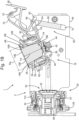
- the first brew chamber part 18 is in an inclined position.
- the open end of the cavity 24 points upwards.
- the first capsule 4A can fall into the cavity 24 under the influence of gravity.
- the rim 14A of the first capsule 4A is guided by an inner surface 36 of the first brew chamber part 18.
- the bottom 8A of the first capsule 4A lowers into the cavity 24 until it abuts against the ejector 38.
- the bottom 8A of the first capsule 4A centers on the ejector 38. It will be appreciated that the rim 14A of the first capsule 4A is positioned between the first abutment surface 26 and the second abutment surface 28.
- the bottom 8A of the first capsule 4A is not yet pierced in this state.
- the second capsule 4B can also fall into the cavity 24 under the influence of gravity.
- the circumferential wall 10B of the second capsule 4B is guided by an inner surface 46 of the first brew chamber part 18.
- the bottom 8B of the second capsule 4B lowers into the cavity 24 until it abuts against the ejector 38.
- the bottom 8B of the second capsule 4B centers on the ejector 38. It will be appreciated that the rim 14B of the second capsule 4B is positioned beyond the second abutment surface 28 when seen from the piercing means 44.
- the bottom 8B of the second capsule 4B is not yet pierced in this state.
- the first brew chamber part 18 can be moved towards the second brew chamber part 20 for closing the brew chamber around the capsule 4A, 4B.
- the first brew chamber part 18 is guided in a frame 48 of the apparatus.
- the first brew chamber part 18 includes first bosses 50 and second bosses 52 as shown in Figs. 2A and 2B .
- the first bosses 50 are guided in a first groove 54 of the frame 48.
- the second bosses 52 are guided in a second groove 56 of the frame 48.
- the bosses 50, 52 and grooves 54, 56 determine the path that will be followed by the first brew chamber part 18.
- the first groove 54 and the second groove 56 are provided in a side wall 57 of the frame 48.
- the first groove 54 extends into the side wall 57 to a first depth.
- the second groove 56 extends into the side wall to a second depth.
- the second depth is larger than the first depth.
- the first boss 50 has a larger diameter than the second boss 52.
- the first groove 54 has a larger width than the second groove 56.
- the width of the first groove 54 corresponds to the diameter of the first boss 50.
- the width of the second groove 56 corresponds to the width of the second boss 52. It will be appreciated that the first groove 54 extends along a different trajectory than the second groove 56.
- the different widths and depths of the grooves allow the first and second bosses 50, 52 to follow different trajectories. This construction allows a very compact construction for guiding the first and second bosses 50, 52.
- the apparatus 2 includes a lever 58.
- the lever can be actuated manually by a user.
- the lever is pivotally connected to the frame 48 around a lever axis 60.
- the first brew chamber part 18 is connected to the frame 48 via a knee joint 62.
- the knee joint 62 includes a push rod 64 and a crank 66.
- the push rod 64 is pivotally connected to the crank 66 at a knee axis 68.
- the crank 66 is pivotally connected to the frame 48 at a crank axis 70.
- the lever 58 is connected to the knee joint 62 for actuating the first brew chamber part 18 in motion.
- the lever 58 is connected to the knee joint 62 through a lever link 74.
- the lever link 74 is pivotally connected to the lever 58 at a lever link axis 76.
- the lever link 74 is pivotally connected to the push rod 74 at a knee link axis 78.
- An arresting ring 80 is arranged surrounding the first brew chamber part 18.
- the arresting ring 80 is axially movable relative to the first brew chamber part 18.
- the arresting ring 80 is guided by an external surface of the first brew chamber part 18.
- the arresting ring is connected to the first brew chamber part via one or more resilient elements 82, here helical springs.
- the push rod is pivotally connected to the arresting ring 80 at a push rod axis 72.
- the knee joint 62 is indirectly connected to the first brew chamber part 18, viz. via the arresting ring 80 and one or more resilient elements 82.
- the function of the arresting ring will be set out below.
- the lever 58 When the lever 58 is moved in a downward direction the knee joint 62 will push the first brew chamber part 18 towards the second brew chamber part 20. Simultaneously, due to the shape of the first and second grooves 54, 56, the first brew chamber part 18 will be rotated from the upwards inclined orientation into a an aligned orientation in which an axial direction of the first brew chamber part 18 is aligned with an axial direction of the second brew chamber part 20.
- the apparatus 2 is arranged for selectively cooperating with either the first capsule 4A or the second capsule 4B.
- the system 1 is arranged for automatically adjusting the brew chamber depending on whether the first or the second capsule has been inserted. This provides the advantage that no user input is required for selecting proper handling of the first or second capsule. Hence, the risk of errors is greatly reduced.
- the second brew chamber part 20 includes an extraction plate 30 with a central portion 32 and a peripheral portion 34.
- the central portion 32 is movable in an axial direction of the second brew chamber part 20.
- the central portion 32 in this example includes a shaft 32' axially slidably movable with respect to the frame 48.
- the central portion 32 is connected to the frame 48 via a resilient member 84, here a helical spring.
- the resilient member 84 biases the central portion into a ready position in Figs. 1A and 1B .
- the ready position is an extended position in this example.
- the central portion 32 can be positioned in a first brewing position for cooperating with the first capsule 4A.
- the central portion can be positioned in a second brewing position for cooperating with the second capsule 4B.
- the system 1 includes a locking mechanism 86 arranged for locking the central portion 32 in or near the first brewing position when the cavity 24 holds the first capsule 4A.
- the locking mechanism 86 includes a locker 88.
- the locker 88 is designed as a pivotable finger, pivotable around a pivoting axis 90.
- the locker 88 is biased into a position pivoted away from the shaft 32'.
- the locker could also be biased into any other suitable position.
- the locking mechanism 86 further includes a pusher 92.
- the pusher is slidably guided in a body 94 of the second brew part 20.
- the pusher 92 is connected to the body 94 via a resilient member 96, here a helical spring.
- the resilient member 96 biases the pusher in an extended position.
- the first brew chamber part 18 includes an actuator 98.
- the actuator is formed by a frontal surface of the first brew chamber part 18.
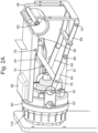
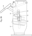
- Figs. 3A and 3B show functioning of the locking mechanism 86 when the cavity 24 holds the first capsule 4A.
- an outermost part of the first capsule 4A here formed by the lid 12A, exit area 13A and/or rim 14A, is positioned rearwardly, i.e. more towards the piercing means 44, relative to the actuator 98.
- the actuator 98 will touch the pusher 92 before the outermost part of the first capsule 4A will touch the central portion 32.
- the pusher is pushed against the biasing force of the resilient member 96.
- a lip 100 of the pusher 92 will slide along a sloping surface 102 of the locker 88, causing the locker 88 to pivot towards the shaft 32'.
- a thumb 104 of the locker 88 is placed in a path of movement of part 106 of the central portion 32 (see Fig. 3B ).
- the pivoted locker 88 prevents travel of the central portion beyond a position where the part 106 abuts against the thumb 104. This is herein defined as the first brewing position.
- the first capsule 4A is arranged for moving the central portion 32 from the ready position to the first brewing position.
- the first capsule 4A is held between the first and second brew chamber parts 18, 20 while brewing, wherein the central portion 32 is in the first brewing position.
- Figs. 4A and 4B show functioning of the locking mechanism 86 when the cavity 24 holds the second capsule 4B.
- an outermost part of the second capsule 4B here formed by the lid 12B, exit area 13B and/or rim 14B, is positioned forwardly, i.e. more towards the second brew chamber part 20, relative to the actuator 98.
- the outermost part of the second capsule 4B will abut against the central portion 32 before the actuator 98 will touch the pusher 92.
- the central portion 32 is pushed against the biasing force of the resilient member 84 while the locker 88 is still pivoted away from the shaft 32'.
- the part 106 passed underneath the thumb 104. Only after the part 106 has passed the thumb 104 the pusher is pushed against the biasing force of the resilient member 96 by the actuator 98. The lip 100 of the pusher 92 will still slide along the sloping surface 102 of the locker 88, causing the locker 88 to pivot towards the shaft 32'. However, the part 106 has already passed the thumb 104 at that moment.
- the second capsule 4B pushes the central portion 32 in abutment with the body 94. This is herein defined as the second brewing position.
- the second capsule 4B is arranged for moving the central portion 32 from the ready position to the second brewing position.
- the second capsule 4B is held between the first and second brew chamber parts 18, 20 while brewing, wherein the central portion 32 is in the second brewing position.
- the locking mechanism 86 is arranged for locking the central portion 32 in the first extraction position when the cavity 24 holds the first capsule 4A. It is noted that the locking may be single-sided, viz. the locking mechanism may prevent the central portion 32 from being moved beyond the first extraction position when the cavity 24 holds the first capsule 4A. However movement of the central portion 32 from the first extraction position to the ready position may be not prevented.
- the locking unit 86 is arranged for selectively preventing the central portion 32 being locked in or near the first brewing position when the second capsule 4B is included in the brew chamber.
- the locking unit 86 is arranged for selectively allowing the central portion 32 being moved into the second brewing position when the second capsule is included in the brew chamber.
- the central portion 32 extends into the cavity 24.
- the central portion 32 extends into the first brew chamber part 18 beyond a position where the lid 12B, exit area 13B and/or rim 14B of the second capsule 4B would have been, had the second capsule been included in the first brew chamber part 18.
- the knee joint 62 is indirectly connected to the first brew chamber part 18, viz. via the arresting ring 80 and one or more resilient elements 82.
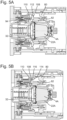
- Figs. 5A-5C demonstrate functioning of the arresting ring 80.
- the first brew chamber part 18 includes a protrusion 108.
- the protrusion 108 is a substantially annular protrusion.
- the protrusion 108 extends outwardly.
- the protrusion 108 forms an outermost edge of the first brew chamber part 18.
- the second brew chamber part 20 includes a retainer 110.
- the retainer 110 is designed as a circumferential ring of retainer lips.
- the retainer 110 is pivotally connected to the body 94.
- the retainer 110 is resiliently pivotally connected to the body 94.
- the retainer 110 includes a tooth 112.
- the tooth here has a first inclined surface 114 and a second inclined surface 116.
- the arresting ring 80 When lowering the lever 58, the arresting ring 80 will be advanced towards the second brew chamber part 20.
- the one or more resilient elements 82 will push the first brew chamber part 18 ahead of the arresting ring 80 until the first brew chamber part abuts against the second brew chamber 20 part, e.g. with the capsule 4A, 4B clamped in between.
- the protrusion 108 will advance against the first inclined surface 114. This causes the retainer 110 to be pivoted outwardly (see Fig. 5A ). Further advancing causes the protrusion 108 to pass beyond the second inclined surface 116, causing the retainer 110 to pivot inwardly (see Fig. 5B ).
- the apparatus can include a fluid supply system for supplying a fluid, e.g. a liquid, such as hot water under pressure, to the first brew chamber part 18.
- a fluid e.g. a liquid, such as hot water under pressure
- the first and second brew chamber parts 18, 20 will be pushed away from each other by the fluid pressure.
- the retainer 110 and arresting ring 80, and optionally the locking ring 118, will bear all, or part of, the force exerted by the fluid pressure.
- the arresting ring 80 interposed between the retainer 110 and the locking ring 118 increases mechanical stability.
- the arresting ring 80 does not have to bear all forces exerted onto it by the retainer 110, since it can abut against the locking ring 118 and transmit at least part of the forces to the locking ring 118.
- the locking ring 118 can be immobile, and hence can easily be reinforced. Since the first brew chamber part is locked onto the second brew chamber part 20 the frame 48 and the actuation mechanism, e.g. the knee joint, do not have to bear this force, or at least a smaller part thereof. Hence the frame and/or the actuation mechanism can be designed weaker and/or cheaper.
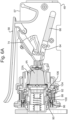
- FIG. 6A shows the first capsule 4A in the brew chamber during extraction.
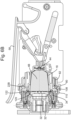
- Fig. 6B shows the second capsule 4B in the brew chamber during extraction.
- the piercing member 44 is arranged for piercing the bottom 8A, 8B of the capsule 4A, 4B. As can also be seen in Figs. 5A-5C , in this example the piercing member 44 does not pierce the bottom 8A, 8B until the lid 12A, 12B of the capsule 4A, 4B abuts against the central portion 32 in the first or second brewing position.
- stiffnesses of the resilient element 42 and the resilient member 84 can be chosen. In this example, the stiffness of the resilient element 42 is chosen to be larger than the stiffness of the resilient member 84. However, it will be appreciated that it is also possible that the stiffness of the resilient element 42 is equal to the stiffness of the resilient member 84 or that the stiffness of the resilient element 42 is smaller than the stiffness of the resilient member 84.
- the beverage preparation apparatus 2 is arranged for preparing a quantity of a beverage, suitable for consumption, using either a first capsule 4A or a second capsule 4B.
- the quantity can be a predetermined quantity.
- the quantity can also be a user selectable, user settable, or user programmable quantity.
- the first sealing member 120 is arranged for providing a fluid sealing engagement between the central portion 32 and the first brew chamber 18 part when forming the brew chamber for holding the first capsule 4A.
- the first sealing member 120 abuts against the first brew chamber part 18 when the first capsule 4A is included in the brew chamber. This provides a seal for water being present in the cavity 24 outside the capsule 4A. This way, brewing fluid injected into the brew chamber 22A is prevented from bypassing around the outside of the capsule 4A.
- the first sealing member 120 includes a resilient lip 121.
- the resilient lip 121 is arranged to provide a self-reinforcing sealing engagement between the central portion 32 and the first brew chamber part 18 under the effect of fluid pressure in the brew chamber.
- the first sealing member 120 abuts against the rim 14A of the first capsule 4A.
- the rim 14A is pressed against the first sealing member 120 by the first abutment surface 26. This provides a sealing engagement between the central portion 32 and the capsule 4A against beverage exiting the capsule 4A via the exit area 13A. It will be appreciated that here the side of the rim 14A facing away from the cup-shaped body 6A is sealed against the second brew chamber part 20.
- the side of the rim 14A facing towards the cup-shaped body 6A can be sealed against the first brew chamber part 18.
- an additional seal can be provided on the first brew chamber part 18, e.g. on the first abutment surface 26, and/or on the capsule 4A, e.g. on the rim 14A.
- a seal on the capsule may be additional to the seal between the first brew chamber part 18 and the second brew chamber part 20. This may reduce the sealing effort by the first sealing member 120.
- the second sealing member 122 is arranged for providing a fluid sealing engagement between the peripheral portion 34 and the first brew chamber 18 part when forming the brew chamber for holding the second capsule 4B.
- the second sealing member 122 abuts against the first brew chamber part 18 when the second capsule 4B is included in the brew chamber. This provides a seal for water being present in the cavity 24 outside the capsule 4B.
- the second sealing member 122 includes a resilient lip 123.
- the resilient lip 123 is arranged to provide a self-reinforcing sealing engagement between the peripheral portion 34 and the first brew chamber part 18 under the effect of fluid pressure in the brew chamber.
- the second sealing member 122 abuts against the rim 14B of the second capsule 4B.
- the rim 14B is pressed against the second sealing member 122 by the second abutment surface 28. This may provide a sealing engagement between the peripheral portion 34 and the capsule 4B against beverage exiting the capsule 4B via the exit area 13B.
- the first sealing member 120 provides a sealing engagement between the central portion 32 and the peripheral portion 34 when forming the brew chamber for holding the second capsule 4B.
- This sealing engagement between the central portion 32 and the peripheral portion 34 can be self-reinforcing. Thereto the engagement between peripheral portion 34 and the second capsule 4B may allow brewing fluid to pass to the first sealing member 120.
- the first sealing member 120 provides a sealing engagement between the central portion 32 and the capsule 4B against beverage exiting the capsule 4B via the exit area 13B.
- the side of the rim 14B facing away from the cup-shaped body 6B which rim may or may not be covered by a lid, for example by a foil, is sealed against the second brew chamber part 20.
- the side of the rim 14B facing towards the cup-shaped body 6B can be sealed against the first brew chamber part 18.
- first brew chamber part 18 e.g. on the second abutment surface 28, and/or on the capsule 4B, e.g. on the rim 14B.
- a seal on the capsule may be additional to the seal between the first brew chamber part 18 and the second brew chamber part 20. This may reduce the sealing effort by the second sealing member 122.
- the exit area 13A, 13B may open against the extraction plate 30.
- the extraction plate 30 in this example includes a plurality of relief elements 124.
- the relief elements 124 are truncated pyramids. A rise in pressure inside the capsule 4A, 4B can cause the exit area 13A, 13B to tear against the relief elements allowing beverage to exit the capsule 4A, 4B.
- the beverage can pass through the extraction plate 30 via apertures in the extraction plate. Next the beverage can flow to an outlet 126. From the outlet 126 the beverage can flow into a receptacle, such as a cup.
- a receptacle such as a cup.
- the lever 58 can be moved upwardly. This causes the arresting ring 80 to be moved away from the retainer 110.
- the first brew chamber part 18 will be moved rearwardly.
- the second inclined surface 116 of the retainer 110 can allow the retainer to pass the projection 108.
- the first brew chamber 18 part will move away from the second brew chamber part 20.
- the central portion 32 will return to the ready position.
- the bosses 50, 52 and grooves 54, 56 determine the path that will be followed by the first brew chamber part 18.
- the first brew chamber part will swivel downwardly. This promotes ejection of the used capsule 4A, 4B from the cavity 24 under the effect of gravity.
- the ejector 38 can assist in pushing the capsule 4A, 4B off the piercing member 44 and out of the cavity 24.
- the used capsule 4A, 4B can fall into a waste basket of the apparatus 2.
- Fig. 8A shows an example of a first capsule 4A inserted in the brew chamber 22A formed by the first brew chamber part 18 and the second brew chamber part 20. It will be appreciated that the circumferential wall 10A is narrower than the cavity 24 at that location. As a result there is a first volume 126 surrounding the first capsule 4A inside the cavity 24.
- Fig. 8B shows an example of a second capsule 4B inserted in the brew chamber 22B formed by the first brew chamber part 18 and the second brew chamber part 20. It will be appreciated that a part 128 of the circumferential wall 10B is narrower than the cavity 24 at that location. This part 128 is formed by the part of the circumferential wall 10B extending beyond the first abutment surface 26. As a result there is a second volume 130 surrounding the second capsule 4B inside the cavity 24.
- first volume 126 is not occupied by the first capsule 4A when the brew chamber holds the first capsule 4A. However, this first volume 126 is occupied by part of the second capsule 4B when the brew chamber holds the second capsule 4B.
- the second volume 130 is not occupied by the second capsule 4B when the brew chamber holds the second capsule 4B. This second volume 130 receiving the central portion 32 of the extraction plate 30 when the brew chamber holds the first capsule 4A.
- the first volume 126 When brewing a beverage using the first capsule 4A, the first volume 126 will fill with fluid, such as water, which fluid is not used for brewing the beverage. This fluid can be drained to the waste basket after brewing.
- the second volume 130 When brewing a beverage using the second capsule 4B, the second volume 130 will fill with fluid, such as water, which fluid is not used for brewing the beverage. This fluid can be drained to a container, e.g. the waste basket, after brewing.
- the first volume 126 is substantially equal to the second volume 130.
- the volume of fluid directed to the waste basket is substantially equal when brewing a beverage using a first capsule 4A and when brewing a beverage using a second capsule 4B.
- FIGs. 9A-9D show the "First" system 1001 as an example of a first embodiment of a system according to the invention.
- Fig. 9A shows the extraction plate 1030 and the second capsule 1004B of the First system 1001 in a straight cross-sectional plane, which contains the central axis of the second capsule 1004B. It is noted that, in this example, the second capsule 1004B is substantially rotational symmetric around said central axis. In Fig. 9A the plane of the extraction plate 1030 is perpendicular to said central axis. For clarity, Fig. 9A shows the extraction plate 1030 at a small distance from the second exit face 1113B of the second capsule 1004B. The relief elements of the extraction plate 1030 are indicated by the reference numeral 1130. In the shown cross-section of Fig. 9A seven relief elements 1130 are seen.
- the reference numeral 1230 indicates a number of beverage outlet passageways through the extraction plate 1030.
- the reference numerals 1013B and 1113B indicate the second exit area and the second exit face, respectively, of the second capsule 1004B.
- the second exit area 1013B defines the area of the second exit face 1113B through which the beverage can potentially exit the second capsule 1004B.
- an area of the second exit face 1113B attached to the flange-like rim 1014B of the second capsule 1004B does not constitute part of the second exit area 1013B.
- Fig. 9B is a perpendicular view onto the second exit face 1113B of the second capsule 1004B in a condition after the second exit face 1113B of the second capsule 1004B has been opened by tearing on the relief elements 1130 of the extraction plate 1030.
- the reference numeral 1213B indicates a number of tear openings in the second exit area 1013B of the second exit face 1113B. These tear openings 1213B are the result of the second exit face 1113B having torn on the relief elements 1130 of the extraction plate 1030. Note that the tear openings in practice can be substantially U-shaped or substantially L-shaped instead of full squares as drawn.
- Figs. 9C-9D are highly similar and analogous to Figs. 9A-9B , respectively, on the understanding that Figs. 9C-9D show the first capsule 1004A of the First system 1001 instead of the second capsule 1004B of the First system 1001. Accordingly, where in Figs. 9C-9D the same reference numerals are used as in Figs. 9A-9B , but with the affixes "A" instead of "B", these corresponding reference numerals relate to similar mutually corresponding parts of the first and second capsules 1004A and 1004B.
- Fig. 9C shows the same extraction plate 1030 as Fig. 9A .
- first exit face 1113A of the first capsule 1004A has a smaller diameter in combination with a higher flow resistance when opened
- second exit face 1113B of the second capsule 1004B has a larger diameter in combination with a lower flow resistance when opened
- it is referred back to the above general introduction of the present document again.
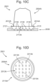
- Figs. 10A-10D show the "Second" system 2001 as an example of a second embodiment of a system according to the invention.
- Figs. 10A-10D are highly similar and analogous to Figs. 9A-9D , respectively.
- the Second system 2001 of Figs. 10A-10D has the first and second capsules 2004A and 2004B, which are identical to the first and second capsules 1004A and 1004B, respectively, of the First system 1001 of Figs. 9A-9D .
- the same reference numerals are used as in Figs. 9A-9D , but with the integer value of such a reference numeral being increased by 1000, these corresponding reference numerals relate to similar mutually corresponding parts of the First and Second systems 1001 and 2001.
- the Second system 2001 of Figs. 10A-10D has an extraction plate 2030, which differs from the extraction plate 1030 of the First system 1001 of Figs. 9A-9D in that the extraction plate 2030 includes first relief elements 2130 of a first type and second relief elements 2131 of a second type, see Figs. 10A , 10C .
- the first relief elements 2130 are arranged within an area corresponding to the first exit face 2113A
- the second relief elements 2131 are arranged within an area corresponding to the second exit face 2113B and outside the area corresponding to the first exit face 2113A. Accordingly, in Fig.
- the reference numeral 2313B indicates a number of tear openings in the second exit area 2013B of the second exit face 2113B. These tear openings 2313B are the result of the second exit face 2113B having torn on the second relief elements 2131 of the extraction plate 2030.
- each of the first relief elements 2130 of the extraction plate 2030 of the Second system 2001 is identical to the type of relief element 1130 of the extraction plate 1030 of the First system 1001.
- the second relief elements 2131 have sharper edges than the first relief elements 2130. Thanks to this sharper edge the second exit face 2113B will tear on the second relief elements 2131 earlier than on the first relief elements 2130. In other words, the second exit face 2113B will tear earlier in its outer ranges than in its inner ranges. This contributes substantially to the aim of obtaining an extraction process being as much as possible uniformly distributed throughout the entire inner space of the second capsule 2004B, which is favourable for the quality of the prepared beverage.
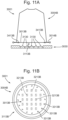
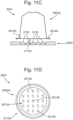
- Figs. 11A-11D show the "Third" system 3001 as an example of a third embodiment of a system according to the invention.
- Figs. 11A-11D are highly similar and analogous to Figs. 9A-9D , respectively.
- the Third system 3001 of Figs. 11A-11D has the first capsule 3004A, which is identical to the first capsule 1004A of the First system 1001 of Figs. 9A-9D . It is noted that, where in Figs. 11A-11D the same reference numerals are used as in Figs. 9A-9D , but with the integer value of such a reference numeral being increased by 2000, these corresponding reference numerals relate to similar mutually corresponding parts of the First and Third systems 1001 and 3001.
- the first difference relates to the extraction plate. That is, the Third system 3001 of Figs. 11A-11D has an extraction plate 3030, which differs from the extraction plate 1030 of the First system 1001 of Figs. 9A-9D in the number of relief elements of the extraction plate.
- each of the relief elements 3130 of the Third system 3001 is identical to the relief element type 1130 of the First system 1001, but, as compared to the pattern of relief elements 1130 of the First system 1001, the pattern of relief elements 3130 of the Third system 3001 is lacking a number of outer peripheral ones of the relief elements.
- the relief element 1130 shown leftmost in each of Figs. 9A and Fig. 9C as well as the relief element 1130 shown rightmost in each of Figs. 9A and Fig. 9C are not present as relief elements 3130 in each of Figs. 11A and Fig. 11C .
- the Third system 3001 of Figs. 11A-11D has a second capsule 3004B, which differs from the second capsule 1004B of the First system 1001 of Figs. 9A-9D in that the second exit face 3113B of the second capsule 3004B includes a weakened zone 3413B, which in Fig. 11A has been depicted in a highly schematic way by means of zigzag lines. It is seen that the weakened zone 3413B is located in a peripheral area of the second exit face 3113B. Accordingly, in Fig. 11B the reference numeral 3313B indicates a number of tear openings in the second exit area 3013B of the second exit face 3113B. These tear openings 3313B are the result of the second exit face 3113B having torn at the weakened zone 3413B (indicated in Fig. 11A ).
- Fig. 12 shows a schematic representation of an extraction plate 30.
- the extraction plate 30 has the central portion 32 and the peripheral portion 34.
- the extraction plate 30 includes a plurality of relief elements 124.
- the central portion 32 includes a plurality of relief elements of a first type 124A.
- the relief elements of the first type 124A are truncated pyramids having a substantially square base.
- the central portion includes twenty five relief elements of the first type 124A.
- the relief elements of the first type 124A are arranged in rows and columns, here in five rows and five columns.
- the relief elements of the first type 124A are arranged within a substantially square area 124B.
- the central portion 32 includes a plurality of relief elements of a second type 124C.
- the relief elements of the second type 124C are positioned outside the substantially square area 124B, in substantially circle-segment shaped areas 124D.
- the relief elements of the second type 124C have a slanted top surface 124E.
- the peripheral portion 34 does not include relief elements.
- the relief elements of the second type 124C are arranged to have sharper edges than the relief elements of the first type 124A. It has been found that this provides more even piercing of the exit area 13A, 13B of a capsule 4A, 4B, than when the relief elements of the second type 124C are arranged to have edges that are as sharp as the relief elements of the first type 124A. Also this aids in having the relief elements outside the substantially square area 124B piercing the exit area 13A, 13B.
- the central portion of the extraction plate includes a plurality of relief elements.
- the peripheral portion includes no relief elements.
- the peripheral portion may also include relief elements.
- the extraction plate and the second exit area can be adapted to each other such that a flow resistance of the second exit area when opened is less than a flow resistance of the first exit area when opened.
- the extraction plate and the second exit area may be adapted to each other such that the second exit area tears on the extraction plate over a larger surface area than the first exit area.
- the extraction plate and the second exit area may be adapted to each other such that the second exit area tears on the extraction plate on more locations than the first exit area.
- Outer relief elements may be designed for tearing both the first and second exit area wherein the second exit area tears on the outer relief elements over a larger surface area than the first exit area.
- the extraction plate can include relief elements of a first type and at least one relief element of a second type, wherein the relief elements of the first type are arranged within an area corresponding to the first exit area, and the at least one relief element of the second type being arranged within an area corresponding to the second exit area and outside the area corresponding to the first exit area.
- the relief element of the second type may have a sharper edge than the relief elements of the first type.
- the second exit area may include a weakened zone. The weakened zone may be located in a peripheral area of the second exit area.
- the first and second capsules have substantially the same shape. It is also possible to provide a third capsule having a different shape.
- the third capsule can e.g. be shaped to substantially fill the brew chamber when the central portion is in the first extraction position. It is also possible to provide a fourth capsule having a different shape.
- the fourth capsule can e.g. be shaped to substantially fill the brew chamber when the central portion is in the second extraction position.
- the first capsule has an outwardly extending flange-like rim. It will be appreciated that it is possible that the first capsule does not include an outwardly extending rim.
- the second capsule has an outwardly extending flange-like rim. It will be appreciated that it is possible that the second capsule does not include an outwardly extending rim.
- the capsule body and lid are made of aluminum foil, preferable polymer coated aluminum foil to allow easy welding of the lid to the body. It will be appreciated that the capsule body and/or lid can be made of a wide variety of materials considered suitable by the skilled person and capable of being processed into a sheet, film or foil using techniques conventionally known in the art such as extrusion, co-extrusion, injection molding, blow molding etc.
- Suitable materials for the capsule body and/or lid include, without being limited thereto, plastic materials, in particular thermoplastic materials, for example a polyolefin polymer, for example polyethylene or polypropylene, PVC, polyesters for example polytherephtalate (PET); metal foils such as aluminum, stainless steel, metal alloys etc.; or sheets of a woven or a non-woven or otherwise processed fibrous material, like paper, polyester, etc.; or combinations thereof, e.g. multilayers.
- the material for the capsule can be a biodegradable polymer or another biodegradable material. The skilled person will be capable of selecting the appropriate material taking into account the envisaged use with food material and any other relevant circumstances during use of the capsule.
- the thickness of the sheet or foil may be chosen such that a form stable capsule is provided. The thickness of the sheet or foil may vary with the nature of the material.
- the capsules are closed capsules. It is also possible to provide the system with an open capsule.
- the open capsule is open prior to insertion into the apparatus.
- the open capsule can be pre-perforated.
- the open capsule can be packaged in a hermetically sealed package, which has to be removed before inserting the open capsule in the apparatus.
- the capsules are pierced by the piercing means. It is also possible to provide the system with a capsule that is not pierced by the piercing means.
- Such capsule can e.g. include an entrance filter.
- the capsules open against the extraction plate. It is also possible to provide the system with a capsule that does not open against the extraction plate.
- Such capsule can e.g. include an exit filter.
- the capsules themselves do not include a sealing member. It will be appreciated that it is possible to provide the capsule with a sealing member, e.g. a resilient sealing member.
- the sealing member can e.g. be placed on the rim, e.g. on the side facing towards the cup-shaped body or on the side facing away from the cup-shaped body. Alternatively, or additionally, a sealing member can be provided on the circumferential wall and/or on the bottom.
- the arresting ring and retainer extend along substantially the entire perimeter of the first and second brew chamber parts. This provides particular good locking of the two brew chamber parts onto each other.
- the arresting ring and retainer include arresting means and retaining means at one or more discrete positions along the perimeter, e.g. at two, three, four, six or eight positions.
- first apparatus arranged for brewing a beverage using a first capsule, but incapable of brewing a beverage using a second capsule.
- first apparatus can be included in a system with the apparatus as described in relation to the figures and a first capsule and optionally a second capsule.
- Such second apparatus can be included in a system with the apparatus as described in relation to the figures and a second capsule and optionally a first capsule.
- any reference signs placed between parentheses shall not be construed as limiting the claim.
- the word 'comprising' does not exclude the presence of other features or steps than those listed in a claim.
- the words 'a' and 'an' shall not be construed as limited to ⁇ only one', but instead are used to mean ⁇ at least one', and do not exclude a plurality.
- the mere fact that certain measures are recited in mutually different claims does not indicate that a combination of these measures cannot be used to an advantage.
Landscapes
- Engineering & Computer Science (AREA)
- Food Science & Technology (AREA)
- Mechanical Engineering (AREA)
- Apparatus For Making Beverages (AREA)
- Non-Alcoholic Beverages (AREA)
- Devices For Dispensing Beverages (AREA)
Applications Claiming Priority (3)
| Application Number | Priority Date | Filing Date | Title |
|---|---|---|---|
| NL2017280A NL2017280B1 (en) | 2016-08-03 | 2016-08-03 | System for preparing a beverage |
| EP17754827.8A EP3493711B1 (de) | 2016-08-03 | 2017-08-03 | System zur zubereitung eines getränks |
| PCT/NL2017/050511 WO2018026271A1 (en) | 2016-08-03 | 2017-08-03 | System for preparing a beverage |
Related Parent Applications (1)
| Application Number | Title | Priority Date | Filing Date |
|---|---|---|---|
| EP17754827.8A Division EP3493711B1 (de) | 2016-08-03 | 2017-08-03 | System zur zubereitung eines getränks |
Publications (2)
| Publication Number | Publication Date |
|---|---|
| EP4428060A2 true EP4428060A2 (de) | 2024-09-11 |
| EP4428060A3 EP4428060A3 (de) | 2024-11-20 |
Family
ID=57530751
Family Applications (2)
| Application Number | Title | Priority Date | Filing Date |
|---|---|---|---|
| EP24190286.5A Pending EP4428060A3 (de) | 2016-08-03 | 2017-08-03 | System zur zubereitung eines getränks |
| EP17754827.8A Active EP3493711B1 (de) | 2016-08-03 | 2017-08-03 | System zur zubereitung eines getränks |
Family Applications After (1)
| Application Number | Title | Priority Date | Filing Date |
|---|---|---|---|
| EP17754827.8A Active EP3493711B1 (de) | 2016-08-03 | 2017-08-03 | System zur zubereitung eines getränks |
Country Status (13)
| Country | Link |
|---|---|
| US (2) | US12161249B2 (de) |
| EP (2) | EP4428060A3 (de) |
| JP (1) | JP7084912B2 (de) |
| KR (1) | KR102369356B1 (de) |
| CN (2) | CN109561781B (de) |
| AU (2) | AU2017307909B2 (de) |
| BR (1) | BR122023002140B1 (de) |
| ES (1) | ES2990109T3 (de) |
| IL (2) | IL264621B2 (de) |
| MX (2) | MX2019001368A (de) |
| NL (1) | NL2017280B1 (de) |
| PL (1) | PL3493711T3 (de) |
| WO (1) | WO2018026271A1 (de) |
Families Citing this family (1)
| Publication number | Priority date | Publication date | Assignee | Title |
|---|---|---|---|---|
| CA3092608A1 (en) | 2018-03-14 | 2019-09-19 | Societe Des Produits Nestle S.A. | Beverage extraction unit for selectively providing orifices of different types in a capsule for extraction of the beverage |
Family Cites Families (174)
| Publication number | Priority date | Publication date | Assignee | Title |
|---|---|---|---|---|
| US4775048A (en) | 1983-05-05 | 1988-10-04 | Alfredo Baecchi | Dispensing unit for manually-operated hot drink dispensing machine with pre-manufactured throwaway capsules of two sizes |
| FR2610502B1 (fr) | 1987-02-11 | 1991-02-08 | Levi Mario | Un dispositif de detection et d'affichage pour machine a cafe express a service automatique |
| GB9007132D0 (en) | 1990-03-30 | 1990-05-30 | Gen Foods Kraft Ltd | Packages containing comestibles |
| GB9007133D0 (en) | 1990-03-30 | 1990-05-30 | Gen Foods Kraft Ltd | Comestibles containing packages |
| ES2066058T3 (es) | 1990-07-27 | 1995-03-01 | Nestle Sa | Procedimiento de extraccion de cartuchos abiertos de cafe, cartucho de cafe y dispositivo de extraccion para efectuar el procedimiento. |
| DK0521187T3 (da) | 1991-07-05 | 1996-03-18 | Nestle Sa | Indretning til ekstraktion af patroner der kan tilpasses til alle espressomaskiner |
| PT891734E (pt) | 1997-07-14 | 2001-01-31 | Nestle Sa | Dispositivo para a confeccao de bebidas |
| IT1297289B1 (it) | 1997-11-03 | 1999-09-01 | San Remo Srl | Dispositivo per l'erogazione di caffe' |
| JPH11249875A (ja) | 1998-02-26 | 1999-09-17 | Nec Ic Microcomput Syst Ltd | プログラミング支援方法及びその装置 |
| EP1063911B1 (de) | 1999-01-19 | 2003-04-16 | Keurig, Incorporated. | Automatisches brühsystem |
| IT1321007B1 (it) | 2000-02-07 | 2003-12-18 | Francesco Bonanno | Gruppo automatico per lo sfruttamento di caffe' e altre bevandemacinate ad azionamento idraulico |
| US6499388B2 (en) | 2000-06-14 | 2002-12-31 | Fianara Interational B. V. | Coffee machine for brewing coffee power pre-packed in a cartridge |
| CZ20012835A3 (cs) | 2000-08-30 | 2002-04-17 | Fianara International B. V. | Kávovar k vaření kávového práąku předbaleného v zásobníku |
| EP1208782B1 (de) | 2000-11-28 | 2004-08-25 | Societe Des Produits Nestle S.A. | Perkolationsvorrichtung |
| WO2003030696A1 (en) | 2001-10-05 | 2003-04-17 | Hp Intellectual Corp. | Coffee maker |
| MXPA04006848A (es) * | 2002-01-16 | 2004-12-08 | Nestle Sa | Capsula cerrada con medio de abertura. |
| ES2194611B2 (es) | 2002-05-08 | 2005-10-16 | Jofemar, S.A. | Sistema de preparacion de bebidas calientes en maquinas automaticas. |
| FR2842092B1 (fr) | 2002-07-12 | 2004-12-24 | Seb Sa | Machine a cafe fonctionnant avec des doses |
| ITPN20020093A1 (it) | 2002-12-02 | 2004-06-03 | Necta Vending Solutions Spa | Gruppo infusore a comando meccanico e fluidodinamico. |
| US7607385B2 (en) | 2003-01-24 | 2009-10-27 | Kraft Foods R & D, Inc. | Machine for the preparation of beverages |
| ITBO20030062A1 (it) | 2003-02-13 | 2004-08-14 | Ima Spa | Capsula utilizzabile per la preparazione di una bevanda infusa. |
| DK1500357T3 (da) | 2003-07-23 | 2006-06-19 | Monodor Sa | Fremgangsmåde til tilberedning af en drik ud fra en kapsel og anordning til fremgangsmådens iværksættelse |
| DE10334526B4 (de) | 2003-07-29 | 2015-07-02 | Wmf Ag | Kaffeebrühvorrichtung mit arretiertem Filterträger |
| ATE475340T1 (de) | 2003-08-18 | 2010-08-15 | Koninkl Philips Electronics Nv | Getränkeherstellungsvorrichtung mit vorsprüngen an der oberen wand der aufgusskammer |
| GB2406329A (en) | 2003-09-29 | 2005-03-30 | Mars Inc | Apparatus for making multiple beverages with reduced cross-contamination |
| DE102004002005A1 (de) | 2004-01-14 | 2005-08-11 | Schifferle, René | Portionskapsel mit gemahlenem Kaffee zur Herstellung eines Kaffeegetränks |
| DE102004004314B4 (de) | 2004-01-28 | 2014-05-15 | Tchibo Gmbh | Brühvorrichtung für eine Kaffeemaschine |
| ITTO20040476A1 (it) | 2004-07-09 | 2004-10-09 | Sgl Italia Srl | Metodo per la preparazione di una bevanda a partire da materiale in polvere disposto in una capsula sigillata. |
| GB2416480B (en) | 2004-07-27 | 2007-12-27 | Kraft Foods R & D Inc | A system for the preparation of beverages |
| DE102004056317A1 (de) | 2004-11-22 | 2006-05-24 | Schifferle, René | Getränkemaschine zur Herstellung eines Heissgetränks durch Aufbrühen und Extrahieren von in einer Kapsel abgepackten Substanzen |
| US20080210098A1 (en) | 2004-12-21 | 2008-09-04 | Martex Holland B.V. | Apparatus for Preparing a Beverage |
| US7337704B2 (en) | 2005-05-25 | 2008-03-04 | Sunbeam Products, Inc. | Single serve beverage maker with coordinated heating and pumping periods |
| EP1910202B1 (de) | 2005-07-29 | 2013-10-02 | Ferag AG | Verfahren und vorrichtung zur kontrolle von klammertransportierten flächigen produkten |
| WO2007016977A1 (de) | 2005-08-05 | 2007-02-15 | Delica Ag | Vorrichtung zum extrahieren eines in einer kapsel enthaltenen extraktionsgutes mit einem flüssigen extraktionsmittel |
| PL1767129T3 (pl) | 2005-09-27 | 2009-04-30 | Nestec Sa | Moduł ekstrakcyjny dla urządzenia do wytwarzania napoju na bazie kapsułki |
| DE102005049624A1 (de) | 2005-10-14 | 2007-07-12 | Niro-Plan Ag | Kaffeemaschine |
| DE202006002678U1 (de) | 2006-02-17 | 2006-04-20 | Eugster/Frismag Ag | Kaffeemaschine zur Zubereitung eines Kaffeegetränks mittels abgepackter, vorportionierter Kaffeepouches |
| ES2344464T3 (es) | 2006-02-27 | 2010-08-27 | Nestec S.A. | Capsula con ingrediente de bebida con elemento para desviar la direccion del chorro. |
| ES2309852T3 (es) | 2006-03-31 | 2008-12-16 | Nestec S.A. | Capsula con un material de junta exterior presurizada mediante un fluido. |
| DE102006016421A1 (de) | 2006-04-07 | 2007-12-06 | Wiesauplast Kunststoff Und Formenbau Gmbh & Co. Kg | Vorrichtung und Verfahren zur portionsweisen Herstellung eines Aromagetränks |
| ES2326909T3 (es) | 2006-04-24 | 2009-10-21 | Nestec S.A. | Capsula para la preparacion de una bebida con un elemento de cierre hermetico unido a la misma y procedimiento de fabricacion de la misma. |
| PT1859714E (pt) | 2006-05-24 | 2009-03-25 | Nestec Sa | Dispositivo de infusão e sistema de infusão de cápsulas com um porta-cápsulas para facilitar introdução e remoção de cápsulas |
| PT1859713E (pt) | 2006-05-24 | 2009-09-24 | Nestec Sa | Dispositivo de infusão para cápsula com mecanismo de fecho de relação de transmissão variável |
| PT1859712E (pt) | 2006-05-24 | 2009-02-02 | Nestec Sa | Módulo de perfuração de cápsulas |
| ITMI20061307A1 (it) | 2006-07-06 | 2008-01-07 | Perfect Steam Appliances Ltd | Gruppo di infusione per macchina per la preparazione di bevande |
| ITFI20060194A1 (it) | 2006-08-04 | 2008-02-05 | Saeco Ipr Ltd | Dispositivo di infusione per la preparazione di bevande da capsule monodose |
| ATE474798T1 (de) * | 2007-01-15 | 2010-08-15 | Swiss Caffe Asia Ltd | Kapsel, mittel zum penetrieren des bodens einer kapsel und vorrichtung für die zubereitung eines getränks |
| ITFI20070028A1 (it) | 2007-02-07 | 2008-08-08 | Saeco Ipr Ltd | Dispositivo di infusione per la preparazione di bevande da capsule monodose con un dispositivo di centraggio delle capsule. |
| DE202007002910U1 (de) | 2007-02-26 | 2007-05-10 | Mahlich, Gotthard | Brüheinheit eines Getränkezubereitungsgeräts |
| EP2266446A1 (de) | 2007-03-29 | 2010-12-29 | Tchibo GmbH | Getränkemaschine und Verfahren zum Zubereiten eines Getränks |
| ITTO20070556A1 (it) | 2007-07-27 | 2009-01-28 | Sgl Italia S R L Con Unico Soc | Gruppo percolatore per la produzione di una bevanda |
| WO2009027131A1 (en) | 2007-08-29 | 2009-03-05 | Nestec S.A. | Dispensing device for preparing and dispensing food and/or nutritional composition |
| EP2058498B1 (de) | 2007-11-09 | 2013-07-10 | Continental Automotive GmbH | Verfahren zur Bestimmung der Kraftstofftemperatur in einem Kraftstoffleitungseinspritzsystem |
| EP2071987B1 (de) | 2007-12-18 | 2010-04-14 | Nestec S.A. | Gerät zur Herstellung eines Getränks mit einem verstellbarem Verschlussmechanismus |
| PT2071986E (pt) | 2007-12-18 | 2012-04-13 | Nestec Sa | Sistema para preparação de uma bebida a partir de ingredientes suportado por uma inserção codificada |
| RU2501512C2 (ru) | 2008-03-14 | 2013-12-20 | Мокофе Аг | Устройство и капсула для приготовления напитка |
| WO2010013274A1 (en) | 2008-08-01 | 2010-02-04 | Rossi Corporation S.R.L. | Espresso coffee machine infusion group |
| JP2012501782A (ja) | 2008-09-13 | 2012-01-26 | エシカル コーヒー カンパニー ソシエテ アノニム | 飲料を調製するための調製デバイス |
| EP2378932B1 (de) | 2008-12-09 | 2014-04-23 | Nestec S.A. | Kapsel zur zubereitung eines getränks durch zentrifugation in einer getränkezubereitungsvorrichtung und dazu ausgelegte vorrichtung |
| IT1392572B1 (it) | 2008-12-30 | 2012-03-09 | Lavazza Luigi Spa | Gruppo di infusione per una macchina per la preparazione di bevande |
| WO2010076698A1 (fr) | 2009-01-02 | 2010-07-08 | Ethical Coffee Company Sa | Capsule pour la preparation d'une boisson et dispositif |
| WO2010084475A2 (fr) | 2009-01-23 | 2010-07-29 | Ethical Coffee Company Sa | Capsule pour la preparation d'une boisson |
| EP2230195B1 (de) | 2009-03-19 | 2018-04-25 | Nestec S.A. | Kapsel mit Filtereinsatz zur Zubereitung von Kaffeegetränken |
| CN201481108U (zh) | 2009-05-11 | 2010-05-26 | 杜伟 | 可更换咖啡胶囊固定器的咖啡胶囊酿造装置 |
| IT1393888B1 (it) | 2009-05-15 | 2012-05-17 | Emmebielle S R L | Macchina per la preparazione di bevande mediante infusione |
| IT1394284B1 (it) | 2009-05-21 | 2012-06-06 | Saeco Strategic Services Ltd | Gruppo di infusione per la preparazione di bevande da confezioni monodose e macchina comprendente detto gruppo |
| PT2303077E (pt) | 2009-06-17 | 2011-11-15 | Sara Lee De Nv | Cápsula para conter ingredientes bebíveis |
| ES2443589T5 (es) | 2009-06-17 | 2020-07-22 | Douwe Egberts Bv | Sistema, cápsula y método para preparar una bebida |
| IT1395966B1 (it) | 2009-08-03 | 2012-11-02 | Torino Politecnico | Macchina per la preparazione di bevande mediante infusione di un prodotto contenuto in una capsula o simile |
| PL2284101T3 (pl) | 2009-08-05 | 2012-02-29 | Nestec Sa | Kapsuła z ukształtowanym reliefowo członem uszczelniającym |
| PT2485629E (pt) | 2009-10-05 | 2014-01-21 | Nestec Sa | Dispositivo de extracção ergonómica de cápsulas |
| DK2509473T3 (da) | 2009-12-08 | 2014-05-19 | Nestec Sa | Kapselsystem med strømningsjusteringsorgan |
| MX2012006501A (es) | 2009-12-08 | 2012-07-03 | Nestec Sa | Sistema, conjunto de capsulas y metodo para preparar una bebida por centrifugacion. |
| DE102009058646A1 (de) | 2009-12-16 | 2011-06-22 | Krüger GmbH & Co. KG, 51469 | Portionskapsel und Verwendung einer Portionskapsel |
| PL2335529T3 (pl) | 2009-12-18 | 2013-01-31 | Delica Ag | Urządzenie do przyrządzania napoju i kapsułka |
| ES2435637T3 (es) | 2009-12-21 | 2013-12-20 | Nestec S.A. | Identificación de cápsulas que contienen ingrediente de bebida |
| RU2555958C2 (ru) | 2010-03-19 | 2015-07-10 | Нестек С.А. | Аппарат для приготовления напитков с использованием капсул, содержащих ингредиенты |
| DE102010003637A1 (de) | 2010-04-01 | 2011-10-06 | BSH Bosch und Siemens Hausgeräte GmbH | Brühkopf einer Heißgetränkezubereitungseinrichtung, Zubereitungseinrichtung mit einem Brühkopf und Betätigungsverfahren dafür |
| PL2374383T3 (pl) | 2010-04-07 | 2013-04-30 | Nestec Sa | System ekstrakcyjny do produkcji napoju wykorzystujący kapsułkę |
| JP2013529524A (ja) | 2010-06-28 | 2013-07-22 | ネステク ソシエテ アノニム | カプセル感知システム |
| EP2401945A1 (de) | 2010-07-01 | 2012-01-04 | Nestec S.A. | Vorrichtung zur Anpassung einer Lebensmittelkapsel in einen Kapselhalter |
| CN101889823B (zh) | 2010-07-15 | 2012-11-07 | 美的集团有限公司 | 胶囊酿造机构及具有该酿造机构的胶囊咖啡机 |
| EP2409608B1 (de) | 2010-07-19 | 2013-05-29 | Nestec S.A. | Vorrichtung zum Fühlen einer Kapsel in einer Getränkeherstellungsvorrichtung |
| ES2399024T3 (es) | 2010-07-22 | 2013-03-25 | Nestec S.A. | Un soporte de cápsula o un adaptador, para adaptar una cápsula en un soporte de cápsula, en una máquina de preparación de bebidas |
| CA2814999A1 (en) * | 2010-08-13 | 2012-02-16 | Koninklijke Douwe Egberts B.V. | Device, system and method for preparing a beverage suitable for consumption from a capsule |
| EP2621317B1 (de) | 2010-09-28 | 2014-04-23 | Nestec S.A. | Vorrichtung und verfahren zur entnahme einer kapsel aus einem getränkeherstellungsgerät |
| IT1401828B1 (it) | 2010-09-28 | 2013-08-28 | Macchiavelli Srl | Sistema per la preparazione di una bevanda a partire da un prodotto da infusione contenuto in una capsula intercambiabile |
| PT2624731E (pt) | 2010-10-08 | 2015-12-07 | Qbo Coffee Gmbh | Aparelho de extração e sistema vedante |
| CA2991233C (en) | 2010-11-09 | 2019-07-23 | La Vit Technology Llc | Capsule based system for preparing and dispensing a beverage |
| JP2014507210A (ja) | 2011-01-27 | 2014-03-27 | ネステク ソシエテ アノニム | 遠心により飲料を調製する為のポッド及びパッケージ |
| CN102188161B (zh) | 2011-01-31 | 2013-01-16 | 苏州工业园区咖乐美电器有限公司 | 一种手动胶囊咖啡机 |
| CN103442624B (zh) | 2011-03-14 | 2017-04-26 | 雀巢产品技术援助有限公司 | 自动饮料机 |
| ITMI20110725A1 (it) | 2011-04-29 | 2012-10-30 | Roberto Celestino Santi | Dispositivo per la produzione di bevande calde. |
| ITMI20110876A1 (it) | 2011-05-18 | 2012-11-19 | Swiss Caffe Asia Ltd | Gruppo infusore, particolarmente per capsule e/o cialde per l'ottenimento di bevande infuse e simili. |
| CA2841241A1 (en) | 2011-07-12 | 2013-01-17 | Nestec S.A. | Pivotally closing beverage ingredient holder with a lock |
| GB201112058D0 (en) | 2011-07-13 | 2011-08-31 | Mars Inc | Beverage preparation capsules |
| KR101232858B1 (ko) * | 2011-07-27 | 2013-02-13 | 한국생산기술연구원 | 웨브의 복수지점의 두께를 측정하는 회전롤이 구비된 두께측정장치및 그 제어방법 |
| EP2785223B1 (de) | 2011-11-30 | 2015-09-30 | Freydman, Philippe | Maschine zur zubereitung von getränken durch extraktion aus kapseln |
| DK2794427T4 (da) | 2011-12-21 | 2021-11-01 | Delica Ag | Kapsel, kapsellegeme, fremgangsmåde og system til tilberedning af en drik |
| CN104254268B (zh) | 2012-02-09 | 2018-03-20 | 库里格绿山股份有限公司 | 具有触动按钮的饮料形成装置和方法 |
| EP2658421B1 (de) | 2012-02-28 | 2016-05-11 | Nestec S.A. | Kapselgesteuerte, motorisierte brüheinheit |
| ITTO20120279A1 (it) | 2012-03-29 | 2013-09-30 | N&W Global Vending Spa | Gruppo infusore per macchine automatiche per la produzione di bevande infuse |
| DE102012006414A1 (de) * | 2012-03-30 | 2013-10-02 | Eugster/Frismag Ag Elektrohaushaltgeräte | Brühvorrichtung zum Extrahieren einer Portionskapsel und Verfahren zum Betrieb einer Brühvorrichtung |
| RU2626940C2 (ru) | 2012-04-11 | 2017-08-02 | Конинклейке Филипс Н.В. | Адаптер для капсулы и система, в которой используется указанный адаптер для капсулы |
| CN104379035B (zh) | 2012-04-24 | 2017-08-15 | 雀巢产品技术援助有限公司 | 饮料制备机的用户接口 |
| ITBS20120073A1 (it) | 2012-04-27 | 2013-10-28 | Capitani Srl | Gruppo di infusione |
| DE202012005191U1 (de) | 2012-05-25 | 2012-06-18 | SEVERIN ELEKTROGERÄTE GmbH | Vorrichtung zum Herstellen eines Getränkes |
| DE102012010394B4 (de) | 2012-05-25 | 2018-11-15 | SEVERIN ELEKTROGERÄTE GmbH | Vorrichtung zum Herstellen eines Getränkes |
| KR102075814B1 (ko) | 2012-06-22 | 2020-02-10 | 터치 커피 & 베버리지스, 엘엘씨. | 음료 브루잉 시스템 |
| DE102012105787A1 (de) | 2012-06-29 | 2014-01-02 | Eugster/Frismag Ag Elektrohaushaltgeräte | System und Verfahren zum Zubereiten eines Getränks |
| RU2015102566A (ru) | 2012-06-29 | 2016-08-20 | К-Фее Зюстем Гмбх | Порционная капсула из пищевого полимера с машиночитаемым идентификатором |
| BR112015001040A2 (pt) | 2012-07-16 | 2017-06-27 | Tuttoespresso Srl | cápsula para preparar uma bebida e sistema para preparar uma bebida |
| ES2875508T3 (es) | 2012-07-16 | 2021-11-10 | Tuttoespresso Srl | Cápsula con un elemento de estanqueidad mejorado, sistema de preparación de bebidas y proceso para la preparación de una bebida |
| CN102743107B (zh) | 2012-07-19 | 2015-05-06 | 宁波圣莱达电器股份有限公司 | 咖啡机冲泡装置 |
| ITTO20120659A1 (it) | 2012-07-26 | 2014-01-27 | Lavazza Luigi Spa | Gruppo erogatore per macchine per la preparazione di bevande tramite capsule |
| WO2014027079A1 (de) | 2012-08-17 | 2014-02-20 | Wilhelm Servis | Kapsel als behälter für einen portionierten brühstoff |
| DE102012108653A1 (de) | 2012-08-20 | 2014-02-20 | Eugster/Frismag Ag Elektrohaushaltgeräte | Brühvorrichtung und Verfahren zum Betrieb einer Brühvorrichtung |
| WO2014029628A1 (en) | 2012-08-22 | 2014-02-27 | Nestec S.A. | Capsule assemblies with data storage and communication means |
| JP6159404B2 (ja) | 2012-08-24 | 2017-07-05 | ネステク ソシエテ アノニム | 食品調製マシンで使用するためのカプセル |
| WO2014041605A1 (ja) | 2012-09-11 | 2014-03-20 | パイオニア株式会社 | スピーカシステム |
| AU2013329653A1 (en) | 2012-10-09 | 2015-04-16 | Nestec S.A. | Extraction unit with a shiftable multi-size cartridge receiver |
| AU2013329854B2 (en) | 2012-10-09 | 2017-11-16 | Nestec S.A. | Beverage machine |
| BR112015007451A2 (pt) | 2012-10-09 | 2017-07-04 | Nestec Sa | unidade de extração de cartucho de múltiplos tamanhos tendo escorregadores de guiamento |
| CN104869874B (zh) * | 2012-10-09 | 2018-01-05 | 雀巢产品技术援助有限公司 | 具有多尺寸料盒腔室的提取单元 |
| EP2908706B1 (de) | 2012-10-19 | 2016-12-14 | Nestec S.A. | Erweiterbare kartuschenaufnahme mit arretierung |
| CN104884368A (zh) | 2012-10-29 | 2015-09-02 | Cstec有限公司 | 用于容纳冲泡物如咖啡、茶叶和类似物的胶囊,以及用于封闭这种胶囊的方法 |
| DE102012111685A1 (de) | 2012-11-30 | 2014-06-05 | K-Fee System Gmbh | Portionskapsel zur Herstellung von Kaffeegetränken mit und ohne Crema |
| DE102012111684A1 (de) | 2012-11-30 | 2014-06-05 | K-Fee System Gmbh | Portionskapsel zur Herstellung eines cremafreien Kaffeegetränks |
| WO2014092406A1 (ko) | 2012-12-10 | 2014-06-19 | 컨벡스코리아(주) | 유니버설 음료 메이커 |
| EP2934243B1 (de) | 2012-12-19 | 2020-03-25 | Société des Produits Nestlé S.A. | Selbstverriegelnde extraktionseinheit für kartuschen in verschiedenen grössen |
| PT2934248T (pt) * | 2012-12-19 | 2019-12-17 | Nestle Sa | Sensor para unidade de extração de cartuchos de dimensões múltiplas |
| CN202960135U (zh) | 2012-12-24 | 2013-06-05 | 厦门优尔电器有限公司 | 一种胶囊安装槽改进的胶囊式咖啡机 |
| ITBS20130026A1 (it) | 2013-03-01 | 2014-09-02 | Bialetti Ind Spa | Dispositivo di infusione per la produzione di una bevanda calda |
| KR102214433B1 (ko) | 2013-03-11 | 2021-02-08 | 네일 엠. 데이 | 커피 음료의 브루잉을 제어하기 위한 방법 및 장치 |
| RU2015145283A (ru) | 2013-03-22 | 2017-04-26 | Нестек С.А. | Капсула с кодом и автоматическая система для приготовления напитков |
| WO2014161089A1 (en) | 2013-04-03 | 2014-10-09 | 2266170 Ontario Inc. | Capsule machine and components |
| ITMI20130667A1 (it) | 2013-04-23 | 2014-10-24 | Imper Spa | Macchina per erogazione di bevande. |
| EP2996520B2 (de) | 2013-05-14 | 2020-06-24 | Delica AG | Brühmodul und system zum zubereiten eines getränks |
| AU2014268094B2 (en) | 2013-05-17 | 2016-11-24 | 2266170 Ontario Inc. | Capsule for preparing consumable product |
| ITTO20130589A1 (it) | 2013-07-12 | 2015-01-13 | Lavazza Luigi Spa | Sistema per la preparazione di bevande |
| KR102155735B1 (ko) | 2013-07-25 | 2020-09-15 | 삼성디스플레이 주식회사 | 증착장치용 증착원 |
| GB201318315D0 (en) | 2013-10-16 | 2013-11-27 | Sab Miller Plc | Dispensing apparatus |
| CN105792712B (zh) | 2013-12-06 | 2020-02-14 | 雀巢产品有限公司 | 胶囊处理装置中的可回缩引导件 |
| WO2015082662A1 (en) * | 2013-12-06 | 2015-06-11 | Nestec S.A. | Device guiding differently sized capsules to extraction |
| CN105792713B (zh) | 2013-12-06 | 2019-06-18 | 雀巢产品技术援助有限公司 | 具有可移动的胶囊排出器的处理设备 |
| CN105813509A (zh) | 2013-12-11 | 2016-07-27 | 雀巢产品技术援助有限公司 | 带有可枢转式胶囊出入口的饮料机 |
| US9474406B2 (en) | 2014-01-17 | 2016-10-25 | Keurig Green Mountain, Inc. | Apparatus with beverage cartridge holder having movable outlet |
| EP3107432A1 (de) | 2014-02-19 | 2016-12-28 | Nestec S.A. | Kapselkit zur verwendung in einer lebensmittelherstellungsmaschine |
| US10687655B2 (en) | 2014-02-25 | 2020-06-23 | Newco Enterprises, Inc. | Beverage brewing device for brewing and removal of different sized beverage capsules |
| CN103829804A (zh) | 2014-03-10 | 2014-06-04 | 宁波凯波集团有限公司 | 胶囊饮料冲泡装置 |
| US9439532B2 (en) | 2014-03-11 | 2016-09-13 | Starbucks Corporation | Beverage production machines with multi-chambered basket units |
| ES2750773T3 (es) | 2014-03-24 | 2020-03-27 | Nestle Sa | Cápsula de café y sistema para producir un extracto de café a partir de dicha cápsula |
| US10188237B2 (en) * | 2014-04-08 | 2019-01-29 | Nestec S.A. | Multisize capsule handling with serial actuation |
| KR20160146859A (ko) | 2014-04-17 | 2016-12-21 | 카-페 시스템 게엠베하 | 일인분 캡슐 및 일인분 캡슐을 사용하여 음료를 준비하는 방법 |
| ES2671034T3 (es) | 2014-05-12 | 2018-06-04 | Nestec S.A. | Unidad de elaboración de bebida particularmente para máquinas para preparar bebidas a partir de cápsulas |
| EP3157395B1 (de) | 2014-06-19 | 2018-04-11 | Tentorio, Massimo | Brühmaschine für einzelportionen |
| GB2528663A (en) | 2014-07-25 | 2016-02-03 | Koninkl Douwe Egberts Bv | A capsule, a beverage preparation system and a method for forming a beverage |
| JP6211741B1 (ja) | 2014-10-10 | 2017-10-11 | コーニンクレッカ フィリップス エヌ ヴェKoninklijke Philips N.V. | 煎出ユニット |
| WO2016071795A1 (en) | 2014-11-06 | 2016-05-12 | Luigi Lavazza S.P.A. | Machine for the preparation of liquid products via capsules and method of assembly |
| CA2961459C (en) | 2014-11-24 | 2018-06-26 | 2266170 Ontario Inc. | Capsule machine and components |
| DE202015100814U1 (de) | 2015-02-20 | 2016-05-27 | Christoph Huber | Dichtung für Kaffeekapseln |
| DE202015100812U1 (de) | 2015-02-20 | 2016-05-27 | Christoph Huber | Dichtung für Kaffeekapseln |
| DE202015100813U1 (de) | 2015-02-20 | 2016-05-27 | Christoph Huber | Dichtung für Kaffeekapseln |
| DE202015101266U1 (de) | 2015-03-11 | 2016-06-15 | Christoph Huber | Dichtung für Kaffeekapseln |
| CN104859874A (zh) * | 2015-04-16 | 2015-08-26 | 天津市弘亚润滑粉制造有限公司 | 一种自动粉末灌装机 |
| NL2017277B1 (en) | 2016-08-03 | 2018-02-14 | Douwe Egberts Bv | Apparatus and method for preparing a beverage and system comprising the apparatus and an exchangeable capsule |
| NL2017278B1 (en) | 2016-08-03 | 2018-02-14 | Douwe Egberts Bv | System, apparatus, method, capsule and kit of capsules for preparing a beverage |
| NL2017284B1 (en) | 2016-08-03 | 2018-02-14 | Douwe Egberts Bv | System and method for preparing a beverage field and background |
| NL2017285B1 (en) | 2016-08-03 | 2018-02-14 | Douwe Egberts Bv | System, apparatus, method, capsule and kit of capsules for preparing a beverage |
| NL2017279B1 (en) | 2016-08-03 | 2018-02-14 | Douwe Egberts Bv | System for preparing a beverage |
| NL2017283B1 (en) | 2016-08-03 | 2018-02-14 | Douwe Egberts Bv | System and apparatus for preparing a beverage |
| NL2017281B1 (en) | 2016-08-03 | 2018-02-14 | Douwe Egberts Bv | System for preparing a beverage |
| NL2019216B1 (en) | 2016-08-03 | 2018-05-04 | Douwe Egberts Bv | System for preparing a quantity of beverage suitable for consumption |
| NL2017282B1 (en) | 2016-08-03 | 2018-02-14 | Douwe Egberts Bv | System for preparing a beverage |
-
2016
- 2016-08-03 NL NL2017280A patent/NL2017280B1/en active
-
2017
- 2017-08-03 CN CN201780048393.5A patent/CN109561781B/zh active Active
- 2017-08-03 BR BR122023002140-1A patent/BR122023002140B1/pt active IP Right Grant
- 2017-08-03 KR KR1020197003721A patent/KR102369356B1/ko active Active
- 2017-08-03 ES ES17754827T patent/ES2990109T3/es active Active
- 2017-08-03 EP EP24190286.5A patent/EP4428060A3/de active Pending
- 2017-08-03 IL IL264621A patent/IL264621B2/en unknown
- 2017-08-03 IL IL303974A patent/IL303974B2/en unknown
- 2017-08-03 WO PCT/NL2017/050511 patent/WO2018026271A1/en not_active Ceased
- 2017-08-03 JP JP2019505057A patent/JP7084912B2/ja active Active
- 2017-08-03 CN CN202111389078.3A patent/CN113951728B/zh active Active
- 2017-08-03 EP EP17754827.8A patent/EP3493711B1/de active Active
- 2017-08-03 MX MX2019001368A patent/MX2019001368A/es unknown
- 2017-08-03 AU AU2017307909A patent/AU2017307909B2/en active Active
- 2017-08-03 PL PL17754827.8T patent/PL3493711T3/pl unknown
-
2019
- 2019-01-31 MX MX2025001053A patent/MX2025001053A/es unknown
- 2019-02-01 US US16/265,945 patent/US12161249B2/en active Active
-
2023
- 2023-11-13 AU AU2023266224A patent/AU2023266224B2/en active Active
-
2024
- 2024-10-31 US US18/934,043 patent/US20250049248A1/en active Pending
Also Published As
Similar Documents
| Publication | Publication Date | Title |
|---|---|---|
| US11129493B2 (en) | System for preparing a beverage | |
| US11395557B2 (en) | Apparatus and method for preparing a beverage and system comprising the apparatus and an exchangeable capsule | |
| US11304555B2 (en) | System and apparatus for preparing a beverage | |
| US20250049248A1 (en) | System for preparing a beverage | |
| CA3032369C (en) | System for preparing a beverage | |
| CA3032365C (en) | System for preparing a beverage |
Legal Events
| Date | Code | Title | Description |
|---|---|---|---|
| PUAI | Public reference made under article 153(3) epc to a published international application that has entered the european phase |
Free format text: ORIGINAL CODE: 0009012 |
|
| STAA | Information on the status of an ep patent application or granted ep patent |
Free format text: STATUS: REQUEST FOR EXAMINATION WAS MADE |
|
| 17P | Request for examination filed |
Effective date: 20240723 |
|
| AC | Divisional application: reference to earlier application |
Ref document number: 3493711 Country of ref document: EP Kind code of ref document: P |
|
| AK | Designated contracting states |
Kind code of ref document: A2 Designated state(s): AL AT BE BG CH CY CZ DE DK EE ES FI FR GB GR HR HU IE IS IT LI LT LU LV MC MK MT NL NO PL PT RO RS SE SI SK SM TR |
|
| REG | Reference to a national code |
Ref country code: DE Ref legal event code: R079 Free format text: PREVIOUS MAIN CLASS: B65D0085804000 Ipc: A47J0031060000 |
|
| PUAL | Search report despatched |
Free format text: ORIGINAL CODE: 0009013 |
|
| AK | Designated contracting states |
Kind code of ref document: A3 Designated state(s): AL AT BE BG CH CY CZ DE DK EE ES FI FR GB GR HR HU IE IS IT LI LT LU LV MC MK MT NL NO PL PT RO RS SE SI SK SM TR |
|
| RIC1 | Information provided on ipc code assigned before grant |
Ipc: A47J 31/36 20060101ALI20241011BHEP Ipc: A47J 31/06 20060101AFI20241011BHEP |
|
| P01 | Opt-out of the competence of the unified patent court (upc) registered |
Free format text: CASE NUMBER: APP_7440/2025 Effective date: 20250213 |
|
| GRAP | Despatch of communication of intention to grant a patent |
Free format text: ORIGINAL CODE: EPIDOSNIGR1 |
|
| STAA | Information on the status of an ep patent application or granted ep patent |
Free format text: STATUS: GRANT OF PATENT IS INTENDED |
|
| INTG | Intention to grant announced |
Effective date: 20260113 |