EP4406671A1 - Verfahren zur bestimmung der übereinstimmung einer walzwerkswalze, verfahren zum walzen von metallband und verfahren zur herstellung eines kaltgewalzten stahlblechs - Google Patents
Verfahren zur bestimmung der übereinstimmung einer walzwerkswalze, verfahren zum walzen von metallband und verfahren zur herstellung eines kaltgewalzten stahlblechs Download PDFInfo
- Publication number
- EP4406671A1 EP4406671A1 EP22889674.2A EP22889674A EP4406671A1 EP 4406671 A1 EP4406671 A1 EP 4406671A1 EP 22889674 A EP22889674 A EP 22889674A EP 4406671 A1 EP4406671 A1 EP 4406671A1
- Authority
- EP
- European Patent Office
- Prior art keywords
- roll
- evaluated
- rolling
- surface shape
- vibration
- Prior art date
- Legal status (The legal status is an assumption and is not a legal conclusion. Google has not performed a legal analysis and makes no representation as to the accuracy of the status listed.)
- Granted
Links
Images


Classifications
-
- B—PERFORMING OPERATIONS; TRANSPORTING
- B21—MECHANICAL METAL-WORKING WITHOUT ESSENTIALLY REMOVING MATERIAL; PUNCHING METAL
- B21B—ROLLING OF METAL
- B21B38/00—Methods or devices for measuring, detecting or monitoring specially adapted for metal-rolling mills, e.g. position detection, inspection of the product
-
- B—PERFORMING OPERATIONS; TRANSPORTING
- B21—MECHANICAL METAL-WORKING WITHOUT ESSENTIALLY REMOVING MATERIAL; PUNCHING METAL
- B21B—ROLLING OF METAL
- B21B37/00—Control devices or methods specially adapted for metal-rolling mills or the work produced thereby
- B21B37/58—Roll-force control; Roll-gap control
-
- B—PERFORMING OPERATIONS; TRANSPORTING
- B21—MECHANICAL METAL-WORKING WITHOUT ESSENTIALLY REMOVING MATERIAL; PUNCHING METAL
- B21B—ROLLING OF METAL
- B21B1/00—Metal-rolling methods or mills for making semi-finished products of solid or profiled cross-section; Sequence of operations in milling trains; Layout of rolling-mill plant, e.g. grouping of stands; Succession of passes or of sectional pass alternations
- B21B1/22—Metal-rolling methods or mills for making semi-finished products of solid or profiled cross-section; Sequence of operations in milling trains; Layout of rolling-mill plant, e.g. grouping of stands; Succession of passes or of sectional pass alternations for rolling plates, strips, bands or sheets of indefinite length
- B21B2001/221—Metal-rolling methods or mills for making semi-finished products of solid or profiled cross-section; Sequence of operations in milling trains; Layout of rolling-mill plant, e.g. grouping of stands; Succession of passes or of sectional pass alternations for rolling plates, strips, bands or sheets of indefinite length by cold-rolling
-
- B—PERFORMING OPERATIONS; TRANSPORTING
- B21—MECHANICAL METAL-WORKING WITHOUT ESSENTIALLY REMOVING MATERIAL; PUNCHING METAL
- B21B—ROLLING OF METAL
- B21B2265/00—Forming parameters
- B21B2265/12—Rolling load or rolling pressure; roll force
-
- B—PERFORMING OPERATIONS; TRANSPORTING
- B21—MECHANICAL METAL-WORKING WITHOUT ESSENTIALLY REMOVING MATERIAL; PUNCHING METAL
- B21B—ROLLING OF METAL
- B21B2267/00—Roll parameters
- B21B2267/24—Roll wear
-
- B—PERFORMING OPERATIONS; TRANSPORTING
- B21—MECHANICAL METAL-WORKING WITHOUT ESSENTIALLY REMOVING MATERIAL; PUNCHING METAL
- B21B—ROLLING OF METAL
- B21B2275/00—Mill drive parameters
- B21B2275/02—Speed
- B21B2275/04—Roll speed
-
- B—PERFORMING OPERATIONS; TRANSPORTING
- B21—MECHANICAL METAL-WORKING WITHOUT ESSENTIALLY REMOVING MATERIAL; PUNCHING METAL
- B21B—ROLLING OF METAL
- B21B37/00—Control devices or methods specially adapted for metal-rolling mills or the work produced thereby
- B21B37/007—Control for preventing or reducing vibration, chatter or chatter marks
-
- B—PERFORMING OPERATIONS; TRANSPORTING
- B21—MECHANICAL METAL-WORKING WITHOUT ESSENTIALLY REMOVING MATERIAL; PUNCHING METAL
- B21B—ROLLING OF METAL
- B21B38/00—Methods or devices for measuring, detecting or monitoring specially adapted for metal-rolling mills, e.g. position detection, inspection of the product
- B21B38/008—Monitoring or detecting vibration, chatter or chatter marks
-
- B—PERFORMING OPERATIONS; TRANSPORTING
- B21—MECHANICAL METAL-WORKING WITHOUT ESSENTIALLY REMOVING MATERIAL; PUNCHING METAL
- B21B—ROLLING OF METAL
- B21B38/00—Methods or devices for measuring, detecting or monitoring specially adapted for metal-rolling mills, e.g. position detection, inspection of the product
- B21B38/08—Methods or devices for measuring, detecting or monitoring specially adapted for metal-rolling mills, e.g. position detection, inspection of the product for measuring roll-force
-
- B—PERFORMING OPERATIONS; TRANSPORTING
- B21—MECHANICAL METAL-WORKING WITHOUT ESSENTIALLY REMOVING MATERIAL; PUNCHING METAL
- B21C—MANUFACTURE OF METAL SHEETS, WIRE, RODS, TUBES, PROFILES OR LIKE SEMI-MANUFACTURED PRODUCTS OTHERWISE THAN BY ROLLING; AUXILIARY OPERATIONS USED IN CONNECTION WITH METAL-WORKING WITHOUT ESSENTIALLY REMOVING MATERIAL
- B21C51/00—Measuring, gauging, indicating, counting, or marking devices specially adapted for use in the production or manipulation of material in accordance with subclasses B21B - B21F
Definitions
- the present invention relates to a method for determining the conformity of a rolling roll, a method for rolling a metal strip, and a method for producing a cold-rolled steel sheet.
- Metal strips such as steel sheets, used for automobiles, beverage cans, and the like, undergo a continuous casting step, a hot rolling step, or a cold rolling step, and then undergo an annealing step or a coating step to become products.
- the cold rolling step is a final step of determining the thickness of the metal strip as the product.
- the coating thickness is sometimes made smaller than before, and the surface properties of the metal strip before the coating step tend to affect the surface properties of the product after the coating step, and therefore the necessity for preventing the generation of surface defects has increased.
- chatter marks are linear marks appearing in the width direction of the metal strip, and are surface defects in which such linear marks periodically appear in the longitudinal direction of the metal strip.
- the chatter marks are considered to be generated by the vibration (hereinafter referred to as chattering) of a rolling mill.
- chattering very slight chatter marks are not identified by visual inspection, sheet thickness measurement, or the like after the cold rolling step, and are recognized for the first time after the coating step in some cases. Therefore, in the meantime, the generation of a large amount of surface defects is not recognized, resulting in a decrease in product yield and a major impediment to productivity.
- sudden fluctuations in the thickness or the tension of the metal strip due to the chattering cause production troubles, such as metal strip breakage, impeding the productivity in some cases.
- a chattering detection method for rolling mill described in PTL 1 detects the vibration in each part of a rolling mill in operation by installing one or more vibration detectors in each part of the rolling mill, and detects chattering in the rolling mill from the detected vibration in each part.
- the chattering detection method for rolling mill the natural frequency of a mill, gear meshing defects, bearing defects, a backlash of the coupling between a spindle and a roll, and the natural frequency generated by roll flaws are individually calculated and set as the basic frequency for every chatter mark generation cause. Then, the vibration displacement, the vibration speed, or the vibration acceleration of each part is detected, and a frequency analysis of the detected vibration displacement, vibration speed, or vibration acceleration of each part is performed.
- the frequency analysis of rolling parameters of a tension, a rolling torque, a rolling speed, a rolling load, and a sheet thickness fluctuation is performed. Then, when the result of performing the frequency analysis of the measured values of the vibrations and the rolling parameters exceed a set value in the frequency of the integral multiple of the basic frequency for every chattering generation cause, the occurrence of the chattering is determined, and the occurrence cause is specified from the basic frequency described above.
- An abnormality detection method in cold rolling or temper rolling described in PTL 2 includes a vibration signal collection step, an FFT frequency analysis step, and a vibration abnormality determination step.
- the vibration signal collection step collects vibration signals detected in at least one small-diameter roll among small-diameter rolls between stands of a cold rolling mill or on the inlet and outlet sides of the cold rolling mill.
- the FFT frequency analysis step performs a frequency analysis of the collected vibration signals by a fast Fourier transform method to obtain frequency components included in the vibration signals and spectrum values thereof.
- the vibration abnormality determination step determines that a vibration abnormality occurs when at least one of a plurality of spectrum values of the same frequency component as a frequency of a string vibration in a plurality of vibration modes of a steel sheet arithmetically operated by a given expression among the frequency components obtained in an execution step of the FFT frequency analysis exceeds a preset threshold value.
- a chatter mark preventing method of a steel sheet described in PTL 3 when a steel sheet having a yield strength of 450 MPa or less after being hot-rolled and pickled is cold-rolled, the natural frequency of a cold rolling mill is made not to coincide with the frequency of the string vibration of the steel sheet in which the length between the final stand of the cold rolling mill and a small-diameter roll first brought into contact with the steel sheet on the outlet side of the cold rolling mill is set as the string length.
- the bending strain generated on the surface of the steel sheet represented by a given equation is set to such a magnitude that the steel sheet is not plastically deformed.
- NPL 1 describes the analysis of a "chattering" phenomenon in cold rolling of an ultra-thin steel sheet. NPL 1 describes the results of a study on the chattering phenomenon occurring during rolling of an ultra-thin cold-rolled steel sheet with a total cold rolling reduction up to 93 to 94%, in which an actual mill research and a theoretical analysis of the rolling behavior were performed to examine measures to prevent the chattering.
- NPL 1 An Analysis of "Chattering" in Cold Rolling for Ultra Thin Gauge Steel Strip, KAWASAKI STEEL GIHO Vol. 8, No. 1, 1976, pp. 60-79
- vibration meters In the conventional technologies described in PTLS 1 to 3, NPL 1, and the like, vibration meters (accelerometers or the like) are installed in a plurality of places in the rolling mill to monitor the vibration behavior during rolling to detect the chattering at an early stage.
- chatter marks are sometimes generated which are difficult to detect only by the vibration measurement of the rolling mill.
- the slight chatter marks mean the formation of irregularities having an amplitude of about 0.1 to 5 um on the surface of the metal strip.
- the slight chatter marks are not identified by visual inspection, sheet thickness measurement, or the like after the cold rolling step, and are sometimes recognized for the first time after the coating step. Therefore, in the meantime, the generation of a large amount of surface defects is not recognized, resulting in a decrease in product yield and a major impediment to productivity.
- chatter marks including the slight chatter marks are generated due to polygonal wear, in which the profile in the circumferential direction of the surface of a rolling roll is polygonized, occurring during the rolling.
- the polygonal wear means that minute irregularities are generated on the surface of the rolling roll in a rolling process of a metal strip, and the irregularities of a specific pitch are grown, polygonizing the surface shape of the rolling roll.
- the present invention has been made to solve the conventional problems. It is an object of the present invention to provide a method for determining the conformity of a rolling roll, a method for rolling a metal strip, and a method for producing a cold-rolled steel sheet, capable of estimating in on-line the state of the polygonal wear of a roll to be evaluated occurring during the rolling, and preventing the slight chatter marks caused by the polygonal wear.
- a method for determining the conformity of a rolling roll is a method for determining the conformity, in a rolling mill including one or two or more stands each having a plurality of rolling rolls, of a rolling roll to be evaluated optionally selected from the plurality of rolling rolls of an optional stand of the stands, and includes: a rolling load data acquisition step of acquiring rolling load operation data of the stand having the roll to be evaluated; a circumferential speed data acquisition step of acquiring circumferential speed operation data of the roll to be evaluated; a vibration analysis step of analyzing the vibration behavior of the stand using the rolling load operation data of the stand having the roll to be evaluated acquired in the rolling load data acquisition step; a surface shape estimation step of estimating the surface shape of the roll to be evaluated during the rolling of a metal strip from the analysis result of the vibration behavior of the stand having the roll to be evaluated by the vibration analysis step and the circumferential speed operation data of the roll to be evaluated acquired in the circumferential speed data acquisition step; and
- a method for rolling a metal strip according to another aspect of the present invention includes, when the conformity of the roll to be evaluated is determined during the rolling of the metal strip using the above-described method for determining the conformity of a rolling roll, and the conformity determination result is nonconformity, replacing the roll to be evaluated with a new rolling roll and rolling the metal strip.
- a method for producing a cold-rolled steel sheet according to another aspect of the present invention includes producing a cold-rolled steel sheet using the above-described method for rolling a metal strip.
- the state of the polygonal wear of the roll to be evaluated occurring during the rolling can be estimated in on-line, and the slight chatter marks caused by the polygonal wear can be prevented.
- chattering an abnormal vibration of each of stands F1 to F5 of a rolling mill a occurring during rolling of a metal strip S is referred to as chattering.
- Periodic-like patterns formed on the surface of the metal strip S by the chattering are referred to as chatter marks.
- the conformity of a roll to be evaluated is determined with the chatter marks having irregularities with an amplitude of about 0.1 to 5 um formed on the surface of the metal strip S, i.e., so-called slight chatter marks, as the target.
- the slight chatter marks are formed due to fluctuations in the thickness of the metal strip S in many cases.
- the slight chatter marks in which minute irregularities are formed, are difficult to detect with sheet thickness gauges 7 installed on the outlet side of the rolling mill a in many cases. Further, even when the surface of the metal strip S after rolling is visually observed, the slight chatter marks are difficult to determine.
- the slight chatter marks are detected after surface treatment, such as coating, is performed or detected for the first time after press-forming of the metal strip S in many cases.
- the chattering causing the chatter marks is considered to be caused by a backlash of bearings, gear meshes, couplings, or the like constituting the rolling mill in many cases.
- the chattering has been conventionally considered to be detectable when vibration data acquired from a vibration meter 5 installed in each of the stands F1 to F5 of the rolling mill a are analyzed, and the magnitude of the vibration in a specific frequency band exceeds a preset threshold.
- the inventors of the present invention have found that some slight chatter marks are difficult to detect with the vibration meter 5 installed in each of the stands F1 to F5 or peripheral facilities thereof of the rolling mill a.
- the inventors of the present invention have found that, in a rolling process of the metal strip S, minute irregularities are generated on the surface of the rolling roll, and the irregularities of a specific pitch are grown, polygonizing the surface shape of the rolling roll (causing polygonal wear).
- Upper and lower work rolls 1, upper and lower backup rolls 2, and upper and lower intermediate rolls 3 are referred to as rolling rolls 1, 2, 3, respectively.
- the vibration of the stands F1 to F5 of the rolling mill a gradually increases during the rolling of the metal strip S to lead to the chattering. Therefore, it is important to estimate the changes in surface shape of the roll to be evaluated.
- FIG. 1 illustrates the schematic configuration of a rolling mill to which a method for determining the conformity of a rolling roll according to one embodiment of the present invention is applied.
- the rolling mill a illustrated in FIG. 1 is a cold rolling mill, and is a tandem mill including a plurality of stands (in this embodiment, the first stand F1 to the fifth stand F5 counting from the inlet side in the threading direction) cold rolling a steel sheet as the metal strip S.
- Other devices e.g., an unwinding machine, a welding machine, a looper on the inlet side, a cutting machine on the outlet side, a winding machine, and the like
- attached to the rolling mill a are not illustrated.
- the first stand F1 to the fourth stand F4 counting from the inlet side in the threading direction are four-stage stands, and the fifth stand F5 counting from the inlet side is a six-high stand.
- Each of the four-stage stands F1 to F4 has the upper and lower work rolls 1 rolling the steel sheet as the metal strip S and the upper and lower backup rolls 2 supporting the upper and lower work rolls 1, respectively, in a housing 4.
- the six-stage stand F5 includes the upper and lower work rolls 1, the upper and lower backup rolls 2, the upper intermediate roll 3, and the lower intermediate roll 3 in the housing 4.
- the upper and lower work rolls 1 roll the steel sheet as the metal strip S.
- the upper and lower backup rolls 2 support the upper and lower work rolls 1, respectively.
- the upper intermediate roll 3 is arranged between the upper work roll 1 and the upper backup roll 2.
- the lower intermediate roll 3 is arranged between the lower work roll 1 and the lower backup roll 2.
- the vibration meter 5 measuring a vibration of each of the stands F1 to F5 is installed.
- the vibration meter 5 is suitably a piezoelectric vibration sensor, and may be a vibration meter of another type.
- a rolling load detector 6 detecting the rolling load of each of the stands F1 to F5 is installed.
- the rolling load detector 6 contains a load cell.
- Tension meter rolls 8 provided between the adjacent stands F1 to F5 each are provided with a tension meter detecting the tension of the steel sheet as the metal strip S. Further, the sheet thickness gauge 7 detecting the sheet thickness of the steel sheet as the metal strip S is installed on the outlet side of each of the first stand F1 and the fifth stand F5.
- a work roll drive device 9 is connected to the upper and lower work rolls 1 of each of the stands F1 to F5, and a roll speed controller 11 controlling the circumferential speeds of the upper and lower work rolls 1 is connected to the work roll drive device 9.
- the roll speed controller 11 is provided with a roll rotational speed detector (not illustrated) detecting the rotational speeds of the upper and lower work rolls 1.
- the upper and lower work rolls 1 of each of the stands F1 to F5 are provided with a roll gap controller 10 controlling the roll gap between the upper and lower work rolls 1.
- the roll gap controller 10 is provided with a rolling-reduction position detector (not illustrated) detecting the rolling-reduction positions of the upper and lower work rolls 1.
- Each of the stands F1 to F5 of the rolling mill a is also provided with a roll replacement device (not illustrated).
- the roll replacement device is provided with a carriage (not illustrated) capable of traveling on rails (not illustrated) in the axial direction of the rolling rolls 1, 2, 3.
- the truck moves to the vicinities of the rolling rolls 1, 2, 3 to be replaced under an instruction from a host computer 14 described later.
- An operator removes the used rolling rolls 1, 2, 3 from the predetermined stands F1 to F5, and then charges new rolling rolls after grinding into the predetermined stands F1 to F5.
- the used rolling rolls 1, 2, 3 are transported to a roll shop to be re-ground.
- a system for producing steel products is constituted by a large-scale hierarchical system to perform production management for a large number of facilities.
- the hierarchical system includes the following hierarchical levels: the host computer 14, which is Level 3, for the highest hierarchy; a control computer 13, which is Level 2, for a production line unit, such as a continuous cold rolling mill; and a control controller 12, which is Level 1, for a facility unit constituting each line.
- the host computer 14 is a business computer
- the control computer 13 is a process computer
- the control controller 12 is a PLC.
- the control computer 13 is connected between the host computer 14 and the subordinate control controller 12, and receives a production plan planned by the host computer 14 and directs the production of the steel sheet as the metal strip S.
- the control computer 13 has main roles of: collecting various kinds of actual result information from the control controller 12 and displaying the actual result information on an operation monitoring screen; and performing an arithmetic operation based on a theoretical model and transmitting information required for the control to the control controller 12.
- the control controller 12 has main roles of: issuing instructions to drives, valves, sensors, and the like constituting a production facility at appropriate timing; adjusting operations such that the devices do not interfere with each other; and actuating sensors while linking count values held by the sensors with physical information, for example.
- the control computer 13 determines rolling operation conditions for the next steel sheet before a welding point of the steel sheet as the metal strip S passes. Specifically, a pass schedule is set according to information, such as base material dimensions (base material sheet thickness and sheet width) and product target sheet thickness, given from the host computer 14, and the control computer 13 determines prediction values of the rolling load and the forward slip of each of the stands F1 to F5 and set values of the roll gap and the roll circumferential speed.
- specification information on the rolling roll including measured values of the roll diameter after grinding (before charged into the stand) and the like is transmitted from the host computer 14 to the control computer 13 as information on the rolling rolls 1, 2, 3 used for each of the stands F1 to F5 for setting the rolling load and the roll circumferential speed.
- the specification information on the rolling roll includes the roll diameter, the roll barrel length, the roll number, the roll material, the surface roughness standard classification, and the like.
- the control controller 12 executes processing to control the roll speed controller 11 of each of the stands F1 to F5 and the roll gap controller 10 of each of the stands F1 to F5 based on the set values (command values) of the roll gap and the roll circumferential speed acquired from the control computer 13.
- the control controller 12 also collects the rolling load of each of the stands F1 to F5 detected by the rolling load detector 6 from the rolling load detector 6 installed in each of the stands F1 to F5. Further, the control controller 12 collects the measured values of the rotational speeds of the upper and lower work rolls 1 from the rotational speed detector of the roll speed controller 11. Further, the control controller 12 continuously collects rolling data, such as tension measurement values, measured by the tension meters provided in the tension meter rolls 8. Then, the control controller 12 outputs the rolling data to the control computer 13 every preset period.
- each of the rolling stands F1 to F5 is provided with the conformity determination device 30 for rolling roll determining the conformity of the roll to be evaluated as illustrated in FIG. 5.
- FIG. 5 illustrates a state in which the conformity determination device 30 for rolling roll is provided only in the first stand F1.
- the conformity determination device 30 estimates the surface shape of the roll to be evaluated generated during the rolling, i.e., polygonal wear state, in on-line. Then, the conformity determination device 30 determines the conformity of the roll to be evaluated based on the estimated surface shape, i.e., polygonal wear state, of the roll to be evaluated, and prevents the slight chatter marks to be generated due to the polygonal wear.
- the roll to be evaluated is the rolling roll optionally selected from the plurality of rolling rolls 1, 2, 3 of an optional stand (F1 to F5) of the stands F1 to F5.
- the upper and lower work rolls 1, the upper and lower backup rolls 2, and the upper and lower intermediate rolls 3 are individually referred to as the rolling rolls.
- the rolling roll optionally selected from the upper and lower work rolls 1 and the upper and lower backup rolls 2 of an optional stand (F1 to F4) is referred to as the roll to be evaluated.
- the rolling roll optionally selected from the upper and lower work rolls 1, the upper and lower backup rolls 2, and the upper and lower intermediate rolls 3 of the stand F5 is referred to as the roll to be evaluated.
- the surface shape of the rolling roll (roll to be evaluated) 1, 2, 3 refers to the cross-sectional shape in the barrel of the rolling roll (roll to be evaluated) 1, 2, 3.
- the rolling roll (roll to be evaluated) 1, 2, 3 has an almost circular cross-sectional shape, and therefore the surface shape is expressed by the deviation amount from a perfect circle of the cross-sectional shape.
- an optional cross section in the axial direction of the barrel may be targeted, but the cross section at the center position of the barrel is preferably targeted.
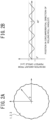
- FIGS. 2A and 2B illustrate a specific example of the surface shape of the rolling roll 1, 2, 3.
- FIG. 2A plots the cross-sectional shape (solid line) of the rolling roll 1, 2, 3 with a reference circle (dashed line) assuming that the cross-sectional shape of the rolling roll 1, 2, 3 is a perfect circle.
- FIG. 2B illustrates the position (angle) in the circle circumferential direction of the rolling roll 1, 2, 3 on the horizontal axis and illustrates the radial deviation amount (deviation amount) of the cross-sectional shape from the perfect circle expressed by the diameter of the rolling roll 1, 2, 3 on the vertical axis.
- the surface shape of the rolling roll (roll to be evaluated) 1, 2, 3 to be estimated of this embodiment is information specified by the relationship between the position in the circumferential direction of the rolling roll (roll to be evaluated) 1, 2, 3 as illustrated in FIG. 2B and the size of the irregularities on the surface.
- the diameter of the rolling roll (roll to be evaluated) 1, 2, 3 serving as the reference when the perfect circle is specified is measured during the grinding of the rolling roll (roll to be evaluated) 1, 2, 3 and is stored in the host computer 14 by an operator.
- the surface shape of the rolling roll (roll to be evaluated) 1, 2, 3 to be estimated in this embodiment does not have to be information specified by a continuous curve as illustrated in FIGS. 2A and 2B .
- the surface of the rolling roll (roll to be evaluated) 1, 2, 3 is equally divided in the circumferential direction, the outer diameters at the opposite positions are measured, the largest diameter and the smallest diameter of the diameters are set as Dmax, Dmin, respectively, and Dmax-Dmin is defined as surface shape information on the rolling roll (roll to be evaluated) 1, 2, 3.
- the number of equal divisions in the circumferential direction ranges from 4 to 36,000 equal divisions, and is more preferably 360 or more equal divisions.
- the surface shape of the rolling roll (roll to be evaluated) 1, 2, 3 is preferably information on the cross-sectional shape related to the pitch of irregularities formed on the rolling roll (roll to be evaluated) 1, 2, 3.
- an irregular shape containing a combination of a plurality of frequency components is sometimes formed in relation to the vibration of each of the rolling stands F 1 to F5.
- a fast Fourier transform method frequency analysis is performed for the relationship between the position (angle information) in the circumferential direction and the deviation amount from the perfect circle of the rolling roll (roll to be evaluated) 1, 2, 3.
- the relationship between the pitch of the irregularities corresponding to the frequency components contained in the surface shape and the spectrum value corresponding to the pitch may be set as the surface shape of the (roll to be evaluated) 1, 2, 3.
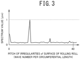
- FIG. 3 illustrates an example of the relationship between the pitch of the irregularities and the spectrum value of the surface of the rolling roll obtained by the frequency analysis by the fast Fourier transform method from the relationship between the position information in the circumferential direction of the rolling roll (roll to be evaluated) 1, 2, 3 and the deviation amount from the perfect circle.
- the surface shape of the rolling roll (roll to be evaluated) 1, 2, 3 to be estimated in this embodiment is amplitude information related to the pitch of the irregularities formed on the surface of the roll to be evaluated as described below.
- the amplitude information is a difference between the maximum value and the minimum value per pitch of the deviation amount from the perfect circle as the cross-sectional shape of the rolling roll (roll to be evaluated) 1, 2, 3.
- the amplitude information related to the pitch of the irregularities is amplitude information when the pitch of the irregularities is preset and the pitch is set as one period.
- the Fourier series expansion of the relationship between the position (angle) in the circumferential direction of the roll to be evaluated and the deviation amount from the perfect circle of the cross-sectional shape is performed, and the Fourier coefficient thus obtained can be defined as the amplitude information related to the pitch.
- the Fourier coefficient is an index representative of the amplitude corresponding to a specific pitch or frequency.
- FIG. 4 schematically illustrates the manner in which the rolling roll is installed in the roll grinder and the surface shape is measured.
- the surface shape of the rolling roll (roll to be evaluated) 1, 2, 3 is measured, the vicinities of both axial ends of the rolling roll (roll to be evaluated) 1, 2, 3 are supported on rests 22.
- one axial end of the rolling roll 1, 2, 3 is fixed by a chuck 21 of a roll rotating device 23, and the other axial end of the rolling roll 1, 2, 3 is pressed in the axial direction by a tailstock 24.
- a displacement meter 26 On the surface of the barrel of the rolling roll 1, 2, 3, a displacement meter 26 is installed which contacts the barrel of the rolling roll 1, 2, 3 and detects the displacement of the surface.
- any contact-type or contactless-type measuring instrument is usable.
- an optional contact-type magnetic scale having relatively high measurement accuracy is preferably used, for example.
- the measurement accuracy of the magnetic scale is about 0.1 to 0.2 um, and one having a measurement stroke of about 1 to 5 mm and a sampling frequency of about 1 kHz is preferably used.
- outputs of the displacement meter 26 are collected by a measuring instrument logger 27 while the rolling roll 1, 2, 3 is rotated at a low speed (e.g., 5 to 10 rpm) by the roll rotating device 23 having a rotating shaft connected to a motor 25.
- a low speed e.g., 5 to 10 rpm
- rotational speed information on the rolling roll 1, 2, 3 is acquired from the roll rotating device 23, and thus the displacement obtained by the displacement meter 26 and the position in the circumferential direction of the rolling roll 1, 2, 3 can be associated with each other.
- the position in the circumferential direction and the displacement information on the rolling roll 1, 2, 3 may be associated with each other by rotating the rolling roll 1, 2, 3 a plurality of times (2 to 5) and obtaining an autocorrelation of the displacement information obtained by the displacement meter 26 to thereby specify displacement information for one rotation.
- the conformity determination device 30 provided in each of the stands F1 to F5 includes an operation data acquisition section 31 having a rolling load data acquisition section 32 and a circumferential speed data acquisition section 33, a vibration analysis section 34, an initial surface shape acquisition section 35, a surface shape estimation section 36, and a conformity determination section 37 as illustrated in FIG. 5 .
- the conformity determination device 30 is a computer system having an arithmetic operation processing function to realize the functions of the operation data acquisition section 31, the vibration analysis section 34, the initial surface shape acquisition section 35, the surface shape estimation section 36, and the conformity determination section 37 by executing programs.
- the computer system can realize the above-described functions on software by executing various dedicated computer programs stored in advance in hardware.
- the operation data acquisition section 31 includes the rolling load data acquisition section 32 and the circumferential speed data acquisition section 33.
- the rolling load data acquisition section 32 acquires information on any of the stands F1 to Fn having the roll to be evaluated selected by an operator from the host computer 14, and, based on the information, performs acquisition processing of rolling load operation data of any of the stands F1 to F5 having the roll to be evaluated.
- the circumferential speed data acquisition section 33 acquires information on any of the stands F1 to Fn having the roll to be evaluated selected by an operator from the host computer 14, and, based on the information, performs acquisition processing of circumferential speed data of the roll to be evaluated.
- the information on any of the stands F1 to Fn having the roll to be evaluated selected by an operator is input in the control computer 13 and transmitted to the operation data acquisition section 31 via the host computer 14.
- the rolling load data acquisition section 32 acquires the rolling load operation data of any of the stands F1 to F5 having the roll to be evaluated from the control controller 12 based on the information described above.
- the rolling load operation data of any of the stands F1 to F5 is the rolling load operation data detected by the rolling load detector 6 during the rolling of the steel sheet as the metal strip S.
- the rolling load operation data is transmitted to the control controller 12, and the rolling load data acquisition section 32 acquires the operation data from the control controller 12.
- a set value of the rolling load set by the control computer 13 may also be set as the rolling load operation data. This is because, as illustrated in FIG.
- the rolling load in the rolling of a metal strip A, a metal strip B, and a metal strip C set by the control computer 13 is set at timing t1, t2, t3, respectively, when a joint between the tip of the metal strip S (A, B, C) and the tail end of the preceding metal strip preceding the metal strip S (A, B, C) passes through the rolling mill a.
- the set value of the rolling load is transmitted from the control computer 13 to the control controller 12, and the rolling load data acquisition section 32 acquires the set value of the rolling load from the control controller 12.
- the rolling load operation data may be transmitted to the vibration analysis section 34 whenever necessary during the rolling of the metal strip S as time series data, and may be transmitted only once to the vibration analysis section 34 at the start of the rolling of the metal strip S.
- the circumferential speed data acquisition section 33 acquires the circumferential speed operation data of the roll to be evaluated from the control controller 12 based on the information described above.
- the circumferential speed operation data of the roll to be evaluated acquired by the circumferential speed data acquisition section 33 is obtained by the conversion using the roll diameter ratio between the upper and lower work rolls 1 and the roll to be evaluated from the measured values of the rotational speeds of the work rolls 1 detected by the rotational speed detector of the roll speed controller 11.
- the operation data for the circumferential speed of the roll to be evaluated is time series data, and the circumferential speed of the roll to be evaluated during the rolling of the steel sheet as the metal strip S is acquired whenever necessary.
- the circumferential speed of the roll to be evaluated is preferably time series data of an optionally set sampling period in the range of 0.1 to 5 ms.
- As the circumferential speed operation data of the roll to be evaluated acquired by the circumferential speed data acquisition section 33 when a speed meter measuring the rotational speed of the roll to be evaluated is installed in each of the stands F1 to F5, the measurement value of the speed meter is usable.
- the operation data for the circumferential speed of the roll to be evaluated is transmitted to the surface shape estimation section 36 whenever necessary during the rolling of the metal strip S.
- the operation data acquisition section 31 may also acquire other operation data when the metal strip S is rolled.
- the surface hardness, the Young's modulus, the Poisson's ratio, and the like of the rolling roll 1, 2, 3 may be acquired as the operation data related to the attribute of the rolling roll 1, 2, 3.
- the operation data related to the rolling conditions the set values or the actual result values of the sheet thickness, the deformation resistance, the rolling reduction, the forward slip, the friction coefficient, and the like of a material to be rolled may be acquired.
- attribute information on the rolling roll 1, 2, 3 affect the ease of wear when the roll to be evaluated comes into contact with the other rolling roll 1, 2, 3 to be worn, which sometimes affects the surface shape of the roll to be evaluated. Further, this is because the operation data illustrated as the rolling condition affects the contact pressure, the relative slip velocity, or the relative slip amount between the roll to be evaluated and the other rolling rolls 1, 2, and 3 in contact with the roll to be evaluated, which sometimes affects the surface shape of the roll to be evaluated.
- the operation data are transmitted to the vibration analysis section 34 or the surface shape estimation section 36.
- the vibration analysis section 34 analyzes the vibration behavior of any of the stands F1 to F5 having the roll to be evaluated using the rolling load operation data of any of the stands F1 to F5 acquired by the rolling load data acquisition section 32.
- the vibration analysis section 34 executes the vibration analysis for the vibration behavior of any of the stands F1 to F5 into which the roll to be evaluated is incorporated, the vibration analysis considering the effect of the rolling rolls 1, 2, 3 other than the roll to be evaluated on the vibration behavior of the roll to be evaluated.
- the upper backup roll 2 of any of the four-stage stands F1 to F4 is selected as the roll to be evaluated.
- the vibration analysis section 34 performs the analysis of the vibration behaviors including the lower backup roll 2, the upper work roll 1, and the lower work roll 1 constituting any of the stands F1 to F4 to determine the vibration behavior of the upper backup roll 2 as the roll to be evaluated.
- a rolling mill vibration model is used in which any of the stands F1 to F5 having the roll to be evaluated is approximated by a mass-spring system. Then, the spring constants in the rolling mill vibration model are updated according to the rolling load operation data of any of the stands F1 to F5 having the roll to be evaluated, and a frequency response when a virtual external force is applied to the rolling mill vibration model with the updated spring constants is calculated.
- the rolling mill vibration model in which any of the four-stage stands F1 to F4 is approximated by the mass-spring system is a vibration model in which the upper and lower work rolls 1 and the upper and lower backup roll 2 are individually set as the material points as illustrated in FIG. 7 , and a damper element can be added as necessary.
- m1 represents the mass of the upper backup roll 2
- m4 represents the mass of the lower backup roll 2
- m2 represents the mass of the upper work roll 1
- m3 represents the mass of the lower work roll 1.
- a spring constant k1 of a spring 41 between the housing and the upper backup roll 2 and a spring constant k5 of a spring 45 between the housing and the lower backup roll 2 represent the spring constants due to the rigidity of the housing and a bearing deformation or a roll deflection of the upper and lower backup rolls 2.
- a spring constant k2 of a spring 42 between the upper backup roll 2 and the upper work roll 1 corresponds to the rigidity due to the elastic contact deformation between the upper backup roll 2 and the upper work roll 1.
- a spring constant k4 of a spring 44 between the lower backup roll 2 and the lower work roll 1 corresponds to the rigidity due to the elastic contact deformation between the lower backup roll 2 and the lower work roll 1.
- a spring constant k3 of a spring 43 between the upper and lower work rolls 1 is the spring constant calculated from the deformation characteristics of the metal strip S when the metal strip S is rolled by the upper and lower work rolls 1.
- a damping element 46 may be provided as necessary, when a hydraulic rolling-reduction device is used as a device lifting and lowering the backup roll 2 by the roll gap controller 10 of each of the stands F1 to F4, for example.
- the spring constant k3 of the spring 43 between the upper and lower work rolls 1 can be calculated based on the ratio of the change amount of the rolling load to the change amount of the gap (roll gap) between the upper and lower work rolls 1.
- calculation considering the flattening deformation (e.g., Hitchcock's roll flattening equation) of the upper and lower work rolls 1 may be performed using a two-dimensional rolling theory, which is an elementary analytical method.
- the two-dimensional rolling theory techniques widely used for the calculation of the rolling load, such as Orowan theory, Karman theory, Bland & Ford's equation, and Hill's approximation, are applicable.
- Mill rigidity K of each of the stands F1 to F4 can be determined from the ratio of changes in load of the rolling load detected by the rolling load detector 6 to changes in roll gap when the upper and lower work rolls 1 are brought into contact with each other during the idling of the mill, and thus the mill stretch curve (elastic characteristic curve) can be obtained.
- a rolling load A' obtained as a simultaneous equation solution with the elasticity characteristic curve of each of the stands F1 to F4 is determined, when a roll gap A serving as the reference is set with the rolling conditions serving as the reference as known values, the rolling conditions serving as the reference including the diameters of the upper and lower work rolls 1, the inlet-side sheet thickness, the inlet-side tension, the outlet-side tension, the deformation resistance of the material to be rolled, and the friction coefficient in a roll bite.
- a rolling load B' is similarly determined when the roll gap A serving as the reference is changed to a roll gap B.
- the ratio of the change amount from the rolling load A' to the rolling load B' to the change amount from the roll gap A to the roll gap B thus obtained can be defined as the spring constant k3.
- the spring constant k2 of the spring 42 between the upper backup roll 2 and the upper work roll 1 and the spring constant k4 of the spring 44 between the lower backup roll 2 and the lower work roll 1 can be calculated by applying the Hertz contact theory for elastic contact deformation of two cylinders.
- the Hertz contact theory is a theoretical solution for contact deformation within the elastic range assuming that no slip or no friction occurs between two contacting solids.
- the axis approach amount, the contact pressure, and the contact length can be determined.
- a coefficient obtained by linear approximation of the relationship between the axis approach amount and the contact load may be set as the spring constant.
- the mill rigidity K of each of the stands F1 to F4 is measured with the upper work roll 1 brought into contact with the lower work roll 1, and therefore a spring constant k3E related to the elastic contact deformation between the upper work roll 1 and the lower work roll 1 is calculated by applying the Hertz contact theory.
- the mill rigidity K of the rolling mill corresponds to a combined spring containing the unknown spring constants k1, k5 and the known spring constants k2, k3E, k4.
- the spring constants k1, k5 can be calculated from the mill rigidity K, the spring constants k2, k3E, k4.
- each of the spring constants k1 to k5 can be determined.
- the method described in NPL 1, for example may be used.
- a damping coefficient when the rolling mill vibration model includes the damping element 46 can be estimated from the damping behavior of the vibration of the housing 4 by performing a hammering test from above the housing 4 with the upper work roll 1 brought into contact with the lower work roll 1.
- the damping coefficient can be determined from a functional equation in which the damping behavior of the amplitude is approximated by an exponential function with respect to a time axis.
- the damping coefficient is a value unique to each of the stands F1 to F4, and therefore a pre-specified damping coefficient may be stored as a fixed value in the vibration analysis section 34.
- the spring constants k1 to k5 of the spring elements constituting the mass-spring model are affected by the rolling load when the metal strip S is rolled. More specifically, the spring constants k1 to k5 calculated by the above-described method intrinsically have non-linear characteristics, but are usually calculated as one that can be linearly approximated in the vicinity of the rolling load when the metal strip S is rolled. Therefore, in the rolling mill vibration model in which each of the stands F1 to F4 is approximated by the mass-spring model as described above, the vibration characteristics change according to the rolling load when the metal strip S is rolled.
- the vibration analysis section 34 of this embodiment updates the spring constants k1 to k5 of the rolling mill vibration model according to the rolling load operation data. More specifically, the vibration analysis section 34 re-sets the spring constants k1 to k5 of the rolling mill vibration model, in which each of the stands F1 to F4 incorporated with the roll to be evaluated is approximated by the mass-spring model, to the latest values according to the rolling load operation data.
- the vibration analysis section 34 may update the spring constants k1 to k5 of the rolling mill vibration model whenever necessary by acquiring time series data of the rolling load from the rolling load data acquisition section 32.
- the rolling load operation data may be updated at least once for the single metal strip S. More specifically, the control computer 13 performs setting and calculation before the metal strip S is rolled, and therefore it may be acceptable that a set value of the rolling load obtained by the setting and calculation is acquired, and the above-described spring constants k1 to k5 are updated using the value.
- the vibration analysis section 34 calculates the frequency response when a virtual external force is applied to the rolling mill vibration model with the updated spring constants k1 to k5.
- Step 1 is a step of calculating the frequency response when the connection to one material point element is virtually opened, and a virtual external force is acted.
- Step 2 is a step of calculating the frequency response when the connections to the other material point elements are virtually opened, and a virtual external force is acted.
- FIG. 8 is a view for explaining an example of calculating the frequency response by virtually opening the connection to the upper backup roll 2 when the upper work roll 1 is selected as the roll to be evaluated in the rolling mill vibration model in which the four-stage stand is approximated by the mass-spring system (Step 1).
- FIG. 9 is a view for explaining an example of calculating the frequency response by virtually opening the connection to the lower work roll 1 when the upper work roll 1 is selected as the roll to be evaluated in the rolling mill vibration model in which the four-stage stand is approximated by the mass-spring system (Step 2).
- the spring 42 (spring constant k2) connected to the material point m1 indicating the upper backup roll 2 above the material point m2 indicating the upper work roll 1 is designated as a connection part C1.
- Step 1 when the spring 42 of the connection part C1 is released, the frequency response for each of the two divided parts of the mass-spring model is calculated.
- the spring 43 (spring constant k3) connected to the material point m3 indicating the lower work roll 1 below the material point m2 indicating the upper work roll 1 is designated as a connection part C2.
- Step 2 when the spring element of the connection part C2 is released, the frequency response for each of the two divided parts of the mass-spring model is calculated.
- a method for calculating the frequency response in Step 1 is described.
- the mass-spring model is divided into a vibration system M1-1 above the connection part C1 and a vibration system M1-2 below the connection part C1.
- a frequency response G1(i ⁇ ) is determined in which an output is the displacement of the material point m1 above the connection part C1 when an upward force (external force) f is acted as an input on the material point m1 indicating the upper backup roll 2 above the connection part C1.
- a frequency response G2(iw) is determined in which outputs are the displacements of the material points m2, m3, m4 below the connection part C1 when a downward force (external force) f is acted as an input on the material point m2 indicating the upper work roll 1 below the connection part C1.
- i represents the imaginary unit and ⁇ represents the angular frequency.
- G 1 (s), G 2 (s) are used.
- the frequency responses G1(i ⁇ ), G2(i ⁇ ) and the transfer functions G 1 (s), G 2 (s) represent the vibration behavior of each of the stands F1 to F4 with the connection part C1 as the center.
- the mass-spring model is divided into a vibration system M2-1 above the connection part C2 and a vibration system M2-2 below the connection part C2.
- a frequency response G3(iw) is determined in which outputs are the displacements of the material points m2, m1 above the connection part C2 when an upward force (external force) f is acted as an input on the material point m2 indicating the upper work roll 1 above the connection part C2.
- a frequency response G4(iw) is determined in which outputs are the displacements of the material points m3, m4 below the connection part C2 when a downward force (external force) is acted as an input on the material point m3 indicating the lower work roll 1 below the connection part C2.
- G 3 (s), G 4 (s) are used.
- the frequency responses G3(iw), G4(iw) and the transfer functions G 3 (s), G 4 (s) represent the vibration behavior of the rolling mill with the connection part C2 as the center.
- G 3 s m 1 s 2 + k 1 + k 2 m 1 s 2 + k 1 + k 2 m 2 s 2 + k 2 ⁇ k 2 2 [Math. 4]
- G 4 s m 4 s 2 + k 5 + k 4 + c 1 s m 4 s 2 + c 1 s + k 5 + k 4 m 3 s 2 + k 4 ⁇ k 4 2
- the frequency response for the connected vibration system may be determined.
- the upper backup roll 2 is selected as the roll to be evaluated in FIG. 7
- the upper backup roll 2 is not connected to another material point element above the upper backup roll 2.
- the spring 41 (spring constant k1) serves as the connection part C1, and there are no vibration systems including the material point element above the connection part C1.
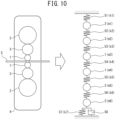
- the rolling mill vibration model in which the six-stage stand F5 is approximated by the mass-spring system is a vibration model with the upper and lower work rolls 1, the upper and lower backup roll 2, and the upper and lower intermediate roll 3 are individually set as the material points as illustrated in FIG. 10 , and a damper element can be added as necessary.
- m1 represents the mass of the upper backup roll 2
- m6 represents the mass of the lower backup roll 2
- m2 represents the mass of the upper intermediate roll 3
- m5 represents the mass of the lower intermediate roll 3
- m3 represents the mass of the upper work roll 1
- m4 represents the mass of the lower work roll 1.
- a spring constant k1 of a spring 51 between the housing and the upper backup roll 2 and a spring constant k7 of a spring 57 between the housing and the lower backup roll 2 represent the spring constants due to the rigidity of the housing and the bearing deformation or the roll deflection of the upper and lower backup rolls 2.
- a spring constant k2 of a spring 52 between the upper backup roll 2 and the upper intermediate roll 3 corresponds to the rigidity due to the elastic contact deformation between the upper backup roll 2 and the upper intermediate roll 3.
- a spring constant k6 of a spring 56 between the lower backup roll 2 and the lower intermediate roll 3 corresponds to the rigidity due to the elastic contact deformation between the lower backup roll 2 and the lower intermediate roll 3.
- a spring constant k3 of a spring 53 between the upper intermediate roll 3 and the upper work roll 1 corresponds to the rigidity due to the elastic contact deformation between the upper intermediate roll 3 and the upper work roll 1.
- a spring constant k5 of a spring 55 between the lower intermediate roll 3 and the lower work roll 1 corresponds to the rigidity due to the elastic contact deformation between the lower intermediate roll 3 and the lower work roll 1.
- a spring constant K4 of a spring 54 between the upper and lower work rolls 1 is the spring constant calculated from the deformation characteristics of the metal strip S when the metal strip S is rolled by the upper and lower work rolls 1. Further, a damping element 58 may be provided as necessary, when a hydraulic rolling-reduction device is used as a device lifting and lowering the backup roll 2 by the roll gap controller 10 of the stand F5, for example.
- the vibration analysis section 34 of this embodiment updates the spring constants k1 to k7 of the rolling mill vibration model according to the rolling load operation data.
- the vibration analysis section 34 may update the spring constants k1 to k7 of the rolling mill vibration model whenever necessary by acquiring the time series data of the rolling load from the rolling load data acquisition section 32.
- changes in spring constants k1 to k7 in the rolling mill vibration model can be practically negligible, and therefore the rolling load operation data may be updated at least once for the single metal strip S.
- control computer 13 performs setting and calculation before the metal strip S is rolled, and therefore it may be acceptable that a set value of the rolling load obtained by the setting and calculation is acquired, and the above-described spring constants k1 to k7 are updated using the value.
- the vibration analysis section 34 calculates the frequency response when a virtual external force is applied to the rolling mill vibration model with the updated spring constants k1 to k7 in which the six-stage stand F5 having the roll to be evaluated is approximated by the mass-spring system.
- Step 1 is a step of calculating the frequency response when the connection to one material point element is virtually opened, and a virtual external force is acted.
- Step 2 is a step of calculating the frequency response when the connections to the other material point elements are virtually opened, and a virtual external force is acted.
- FIG. 11 is a view for explaining an example of calculating the frequency response by virtually opening the connection to the upper backup roll 2 when the upper intermediate roll 3 is selected as the roll to be evaluated in the rolling mill vibration model in which the six-stage stand is approximated by the mass-spring system (Step 1).
- FIG. 12 is a view for explaining an example of calculating the frequency response by virtually opening the connection to the upper work roll 1 when the upper intermediate roll 3 is selected as the roll to be evaluated in the rolling mill vibration model in which the six-stage stand is approximated by the mass-spring system (Step 2).
- the spring 52 (spring constant k2) connected to the material point m1 indicating the upper backup roll 2 above the material point m2 indicating the upper intermediate roll 3 is designated as a connection part C3.
- Step 1 when the spring 52 of the connection part C3 is released, the frequency response for each of the two divided parts of the mass-spring model is calculated.
- the spring 53 (spring constant k3) connected to the material point m3 indicating the upper work roll 1 below the material point m2 indicating the upper intermediate roll 3 is designated as a connection part C4.
- Step 2 when the spring element of the connection part C4 is released, the frequency response for each of the two divided parts of the mass-spring model is calculated.
- a method for calculating the frequency response in Step 1 is described.
- the mass-spring model is divided into a vibration system M3-1 above the connection part C3 and a vibration system M3-2 below the connection part C3.
- a frequency response G5(iw) is determined in which an output is the displacement of the material point m1 above the connection part C3 when an upward force (external force) f is acted as an input on the material point m1 indicating the upper backup roll 2 above the connection part C3.
- a frequency response G6(iw) is determined in which outputs are the displacements of the material points m2, m3, m4, m5, m6 below the connection part C3 when a downward force (external force) f is acted as an input on the material point m2 indicating the upper intermediate roll 3 below the connection part C3.
- i represents the imaginary unit and ⁇ represents the angular frequency.
- G 5 (s), G 6 (s) are used.
- the frequency responses G5(iw), G5(iw) and the transfer functions G 5 (s), G 6 (s) represent the vibration behavior of the stand F5 with the connection part C3 as the center.
- the mass-spring model is divided into a vibration system M4-1 above the connection part C4 and a vibration system M4-2 below the connection part C4.
- a frequency response G7(iw) is determined in which outputs are the displacements of the material points m2, m1 above the connection part C4 when an upward force (external force) f is acted as an input on the material point m2 indicating the upper intermediate roll 3 above the connection part C4.
- a frequency response G8(iw) is determined in which outputs are the displacements of the material points m3, m4, m5, m6 below the connection part C4 when a downward force (external force) is acted as an input on the material point m3 indicating the upper work roll 1 below the connection part C4.
- G 7 (s), G 8 (s) are used.
- the frequency responses G7(i ⁇ ), G8(i ⁇ ) and the transfer functions G 7 (s), G 8 (s) represent the vibration behavior of the rolling mill with the connection part C4 as the center.
- G 6 (s) is represented by Equation (6), in which the denominator is (m 6 s 2 + c 1 s + k 7 + k 6 ) (m 5 s 2 + k 6 + k 5 ) (m 4 s 2 + k 5 + k 4 ) (m 3 s 2 + k 4 + k 3 ) (m 2 s 2 + k 3 ) -k 6 2 (m 4 s 2 + k 5 + k 4 ) (m 3 s 2 + k 4 + k 3 ) (m 2 s 2 + k 3 ) -k 5 2 (m 6 s 2 + c 1 s + k 7 + k 6 ) (m 3 s 2 + k 4 + k 3 ) (m 2 s 2 + k 3 ) -k 4 2 (m 6 s 2 + c 1 s + k 7 + k 6 ) (m 3 s 2 + k 4 + k 3 ) (m 2
- G 8 (s) is represented by Equation (8), in which the denominator is (m 6 s 2 + c 1 s + k 7 + k 6 ) (m 5 s 2 + k 6 + k 5 ) (m 4 s 2 + k 5 + k 4 ) (m 3 s 2 + k 4 )-k 4 2 ⁇ (m 6 s 2 + c 1 s + k 7 + k 6 ) (m 5 s 2 + k 6 + k 5 ) -k 6 2 ⁇ -k 6 2 (m 4 s 2 + k 5 + k 4 ) (m 3 s 2 + k 4 ) -k 5 2 (m 6 s 2 + c 1 s + k 7 + k 6 ) (m 3 s 2 + k 4 ), and the numerator is - (m 6 s 2 + c 1 s + k 7 + k 6 ) (m 5 s 2 + k 6 + k 3
- the frequency response for the connected vibration system may be determined.
- the initial surface shape acquisition section 35 acquires, from the host computer 14, the initial surface shape of the roll to be evaluated before the roll to be evaluated is incorporated into any of the stands F1 to F5 having the roll to be evaluated.
- the initial surface shape of the roll to be evaluated indicates the initial amplitude of the surface of the roll to be evaluated before the roll to be evaluated is incorporated into any of the stands F1 to F5, and is a parameter specified after the roll to be evaluated is ground by a roll grinder. Specifically, an operator measures the surface shape of the roll to be evaluated after grinding, and a difference between the measured maximum diameter and minimum diameter can be determined as an initial amplitude ⁇ .
- the surface shape information on the roll to be evaluated before the roll to be evaluated is incorporated into any of the stands F1 to F5
- the initial surface shape of the roll to be evaluated is input in the control computer 13 by an operator when the operator inputs information on the selected roll to be evaluated in the control computer 13, and is transmitted to the initial surface shape acquisition section 35 via the host computer 14.
- the surface shape estimation section 36 estimates the surface shape of the roll to be evaluated using the initial surface shape of the roll to be evaluated acquired by the initial surface shape acquisition section 35 in addition to the analysis result of the vibration behavior of any of the stands F1 to F5 having the roll to be evaluated by the vibration analysis section 34 and the circumferential speed operation data of the roll to be evaluated acquired by the circumferential speed data acquisition section 33.
- the analysis result of the vibration behavior of any of the stands F1 to F5 having the roll to be evaluated by the vibration analysis section 34 is the frequency response calculated as follows, and is transmitted from the vibration analysis section 34 to the surface shape estimation section 36. More specifically, when the frequency response is calculated, the rolling mill vibration model is used in which any of the stands F1 to F5 having the roll to be evaluated is approximated by the mass-spring system. Then, the spring constants k1 to k7 in the rolling mill vibration model are updated according to the rolling load operation data of any of the stands F1 to F5 having the roll to be evaluated. The frequency response is calculated when a virtual external force is applied to the rolling mill vibration model with the updated spring constants k1 to k7.
- the circumferential speed operation data of the roll to be evaluated acquired by the circumferential speed data acquisition section 33 is transmitted from the circumferential speed data acquisition section 33 to the surface shape estimation section 36.
- the roll to be evaluated incorporated into any of the stands F1 to F5 receives a periodic contact load from the other rolling rolls contacting the roll to be evaluated during the rolling of the metal strip S or the metal strip S as the material to be rolled.
- the periodic contact load in this case acts on the roll to be evaluated as a load containing a combination of vibrations of a plurality of frequencies.
- Such a load on the roll to be evaluated gradually progresses the wear between solids in contact with each other, resulting in the development of irregularities of a specific period and polygonization of the surface shape of the roll to be evaluated in some cases.
- a small relative slip corresponding to the vibration frequency occurs between the roll to be evaluated and the other solids with which the roll to be evaluated comes into contact, and small wear due to the slip is grown at a specific pitch, polygonizing the surface shape of the roll to be evaluated.
- the surface shape estimation section 36 estimates the surface shape of the roll to be evaluated formed during the rolling of the metal strip S using an index representative of the degree of damage of the roll to be evaluated received from contacting other solids when such vibrations of a plurality of frequencies are given to the roll to be evaluated.
- the surface shape estimation section 36 estimates the surface shape of the roll to be evaluated using a parameter referred to as a "pitch damage degree” described below.
- the "pitch damage degree” is the parameter for calculating the damage degree related to the pitch of the irregularities formed on the surface of the roll to be evaluated from the frequency response characteristics of each of the stands F1 to F5 calculated using the rolling mill vibration model in the vibration analysis section 34 and the operation data of a circumferential speed V (m/sec) of the roll to be evaluated acquired by the circumferential speed data acquisition section 33, and can be defined as follows.
- a pitch damage degree ⁇ 1(p) for the connection part C1 calculated in Step 1 is represented by Equation (9) below using frequency responses G1(i ⁇ ), G2(iw).
- Equation (9) a pitch damage degree ⁇ 1(p) for the connection part C1 calculated in Step 1 is represented by Equation (9) below using frequency responses G1(i ⁇ ), G2(iw).
- ⁇ ⁇ 1 p ⁇ vk 0 T 1 1 + k 0 G 1 i ⁇ 0 1 ⁇ k 0 G 2 i ⁇ 0 + k 0 2 G 1 i ⁇ 0 G 2 i ⁇ 0
- the pitch damage degree ⁇ 1(p) is associated with the wear amount (damage degree) of pitch irregularities formed on the surface of the roll to be evaluated caused by the vibration in the connection part C1, and is equivalent to the change amount per unit time of a value obtained by causing the natural logarithm to act on the amplitude of the pitch irregularities.
- a pitch damage degree ⁇ 2(p) for the connection part C2 is represented by Equation (11) below using the frequency responses G3(iw), G4(iw).
- Equation (11) a pitch damage degree for the connection part C2 is represented by Equation (11) below using the frequency responses G3(iw), G4(iw).
- ⁇ ⁇ 2 p ⁇ vk 0 T 1 1 + k 0 G 3 i ⁇ 0 1 ⁇ k 0 G 4 i ⁇ 0 + k 0 2 G 3 i ⁇ 0 G 4 i ⁇ 0
- ⁇ t is the sampling period of the circumferential speed of the rolling roll acquired by the operation data acquisition section.
- the pitch damage degree ⁇ (p) sometimes becomes negative depending on the rolling conditions, and this case means that the irregularities corresponding to the pitch p gradually become smaller.
- ⁇ represents the initial surface shape of the roll to be evaluated input from the initial surface shape acquisition section 35, i.e., the initial amplitude of the surface of the roll to be evaluated before the roll to be evaluated is incorporated into any of the stands F1 to F4, and is the parameter specified after the roll to be evaluated is ground by a roll grinder. Specifically, an operator measures the surface shape of the roll to be evaluated after grinding, and a difference between the measured maximum diameter and minimum diameter can be determined as the initial amplitude ⁇ .
- the initial amplitude u0(p) is specified for every pitch p by the Fourier series expansion for the surface profile in the circumferential direction of the roll to be evaluated after roll grinding.
- the amplitude information u(p) corresponding to the pitch p can be calculated using the same technique as above.
- the surface shape of the roll to be evaluated may be estimated based on the past operation actual results of the actual result data of the frequency response of each of the stands F1 to F5 and the circumferential speed of the roll to be evaluated and the surface shape of the roll to be evaluated.
- the surface shape of the roll to be evaluated estimated by the surface shape estimation section 36 i.e., amplitude information u(p) corresponding to the pitch p of the surface of the roll to be evaluated, is transmitted to the conformity determination section 37 connected to the surface shape estimation section 36.
- the conformity determination section 37 determines the conformity of the roll to be evaluated based on the surface shape of the roll to be evaluated estimated by the surface shape estimation section 36. More specifically, the conformity determination section 37 refers to the value of the amplitude information u(p) corresponding to the pitch p of the surface of the roll to be evaluated calculated by the surface shape estimation section 36. Then, the conformity determination section 37 determines a case where the value of the amplitude information u(p) corresponding to the pitch p of the roll to be evaluated is less than the upper limit of the amplitude corresponding to the preset pitch p as conformity (accepted), and a case where the value is equal to or more than the upper limit as nonconformity (rejected).
- the upper limit of the amplitude corresponding to the preset pitch p is the upper limit of the amplitude corresponding to the pitch p, which is set as the surface shape of the roll to be evaluated in advance when it is turned out that the irregularities at a specific pitch p are likely to grow from the past operation actual results or the past generation actual results of the chatter marks.
- the rolling roll replacement timing can be properly managed, and a decrease in the production efficiency or a working ratio of the rolling mill a can be prevented.
- the determination results by the conformity determination section 37 are transmitted to the display device 38 connected to the conformity determination section 37.
- the display device 38 displays the output of the result, i.e., the determination result by the conformity determination section 37.
- the method for determining the conformity of a rolling roll determines the conformity of the roll to be evaluated which is the rolling roll optionally selected from the plurality of rolling rolls 1, 2, 3 of the optional stand (F1 to F5) using the conformity determination device 30 for rolling roll.
- FIG. 6 is a flowchart for explaining the flow of processing in the host computer 14 and the conformity determination device 30 of the rolling mill a illustrated in FIG. 5 .
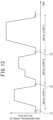
- FIG. 13 is a graph showing changes in circumferential speed of the rolling roll 1, 2, 3 and the conformity determination timing of the roll to be evaluated when continuous rolling of the metal strip S is performed using the rolling mill a illustrated in FIG. 5 .
- the normal rolling mill a continuously rolls the plurality of metal strips S, and therefore, in the example illustrated in FIG. 13 , the rolling is performed in the order of the metal strips A, B, C.
- the tip of the metal strip A and the tail end of the preceding metal strip preceding the metal strip A are joined by welding.
- the processing in the host computer 14 and the conformity determination device 30 of the rolling mill a illustrated in FIG. 6 is performed.
- an operator Prior to the processing in the host computer 14 and the conformity determination device 30 in FIG. 6 , an operator inputs information on the selected roll to be evaluated and the initial surface shape of the roll to be evaluated (initial amplitude ⁇ of the surface of the roll to be evaluated) in the control computer 13, and the information is input in the host computer 14.
- the information on the selected roll to be evaluated is the information on which rolling roll of the plurality of rolling rolls 1, 2, 3 of any of the stands F1 to F5 is selected as the roll to be evaluated.
- the host computer 14 selects the roll to be evaluated based on the information input in the host computer 14 in Step S1. Then, the host computer 14 transmits the information on the selected roll to be evaluated to the operation data acquisition section 31 of the conformity determination device 30 provided in any of the stands F1 to F5 having the roll to be evaluated. Further, the host computer 14 transmits information on the initial surface shape of the roll to be evaluated to the initial surface shape acquisition section 35 of the conformity determination device 30 provided in any of the stands F1 to F5 having the roll to be evaluated (roll to be evaluated selection step).
- Step S2 the initial surface shape acquisition section 35 of the conformity determination device 30 provided in any of the stands F1 to F5 having the roll to be evaluated acquires the information on the initial surface shape of the roll to be evaluated, i.e., initial amplitude ⁇ of the surface of the roll to be evaluated, from the host computer 14 (initial surface shape acquisition step).
- the initial surface shape acquisition section 35 may acquire one in which the initial amplitude u0(p) is specified for every pitch p by the Fourier series expansion for the surface profile in the circumferential direction of the roll to be evaluated after roll grinding as the surface shape information on the roll to be evaluated.
- Step S3 the rolling load data acquisition section 32 of the conformity determination device 30 provided in any of the stands F1 to F5 having the roll to be evaluated acquires the rolling load operation data of any of the stands F1 to F5 having roll to be evaluated from the control controller 12 based on the selection information on the roll to be evaluated from the host computer 14 (rolling load data acquisition step).
- the rolling load operation data of the stands F1 to F5 is the rolling load operation data detected by the rolling load detector 6 when the joint between the metal strip A and the preceding metal strip passes through the stands F1 to F5.
- a set value of the rolling load set by the control computer 13 may also be set as the rolling load operation data. This is because, at the timing t1 when the joint between the tip of the metal strip A and the tail end of the preceding metal strip preceding the metal strip A passes through the rolling mill a, the rolling load in the rolling of the metal strip A by the control computer 13 is set.
- Step S4 the circumferential speed data acquisition section 33 of the conformity determination device 30 provided in any of the stands F1 to F5 having the roll to be evaluated acquires the circumferential speed operation data of the roll to be evaluated from the control controller 12 based on the selection information on the roll to be evaluated from the host computer 14 (circumferential speed data acquisition step).
- the circumferential speed operation data of the roll to be evaluated acquired by the circumferential speed data acquisition section 33 is obtained by the conversion using the roll diameter ratio between the upper and lower work rolls 1 and the roll to be evaluated from the measured values of the rotational speed of the work rolls 1 detected by the rotational speed detector of the roll speed controller 11.
- Step S5 the vibration analysis section 34 of the conformity determination device 30 provided in any of the stands F1 to F5 having the roll to be evaluated analyzes the vibration behavior of any of the stands F1 to F5 having the roll to be evaluated using the rolling load operation data of any of the stands F1 to F5 acquired in Step S3 (rolling load acquired step) (vibration analysis step).
- the rolling mill vibration model in which any of the stands F1 to F5 having the roll to be evaluated is approximated by the mass-spring system is used as described above.
- the spring constants k1 to k5 in the rolling mill vibration model are updated according to the rolling load operation data of any of the stands F1 to F5 having the roll to be evaluated acquired in Step S3.
- the frequency response is calculated when a virtual external force is applied to the rolling mill vibration model with the updated spring constants k1 to k5.
- the transfer functions G 1 (s), G 2 (s), G 3 (s), G 4 (s) indicating the frequency responses G1(i ⁇ ), G2(iw), G3(i ⁇ ), G4(i ⁇ ) corresponding to the examples in FIGS. 8 and 9 of the four-stage stands F1 to F4 can be represented by Equations (1) to (4) above, respectively.
- the transfer functions G 5 (s), G 6 (s), G 7 (s), G 8 (s) indicating the frequency responses G5(iw), G6(iw), G7(i ⁇ ), G8(i ⁇ ) corresponding to the examples in FIGS. 11 and 12 of the six-stage stand F5 can be represented by Equations (5) to (8) above, respectively.
- the surface shape estimation section 36 estimates the surface shape of the roll to be evaluated during the rolling of the metal strip S (surface shape estimation step).
- the analysis result of the vibration behavior of any of the stands F1 to F5 having the roll to be evaluated by Step S5 (vibration analysis step) is used.
- the circumferential speed operation data of the roll to be evaluated acquired in Step S4 circumferential speed data acquisition step
- the initial surface shape of the roll to be evaluated acquired in Step S2 initial surface shape acquisition step
- the analysis result of the vibration behavior of any of the stands F1 to F5 having the roll to be evaluated by Step S5 is the frequency response calculated as follows, and is transmitted from the vibration analysis section 34 to the surface shape estimation section 36. More specifically, when the frequency response is calculated, the rolling mill vibration model is used in which any of the stands F1 to F5 having the roll to be evaluated is approximated by the mass-spring system. Then, the spring constants k1 to k7 in the rolling mill vibration model are updated according to the rolling load operation data of any of the stands F1 to F5 having the roll to be evaluated. The frequency response is calculated when a virtual external force is applied to the rolling mill vibration model with the updated spring constants k1 to k7.
- the circumferential speed operation data of the roll to be evaluated acquired in Step S4 (circumferential speed data acquisition step) is transmitted from the circumferential speed data acquisition section 33 to the surface shape estimation section 36.
- the roll to be evaluated incorporated into any of the stands F1 to F5 receives a periodic contact load from the other rolling rolls contacting the roll to be evaluated during the rolling of the metal strip S or the metal strip S as the material to be rolled.
- the periodic contact load in this case acts on the roll to be evaluated as a load containing a combination of vibrations of a plurality of frequencies.
- Such a load on the roll to be evaluated gradually progresses the wear between solids in contact with each other, resulting in the development of irregularities of a specific period and polygonization of the surface shape of the roll to be evaluated in some cases.
- a small relative slip corresponding to the vibration frequency occurs between the roll to be evaluated and the other solids with which the roll to be evaluated comes into contact, and small wear due to the slip is grown at a specific pitch, polygonizing the surface shape of the roll to be evaluated.
- Step S6 the surface shape estimation section 36 estimates the surface shape of the roll to be evaluated formed during the rolling of the metal strip S using an index representative of the degree of damage of the roll to be evaluated received from contacting other solids when such vibrations of a plurality of frequencies are given to the roll to be evaluated.
- the surface shape estimation section 36 estimates the surface shape of the roll to be evaluated using the parameter referred to as the "pitch damage degree" described above.
- the "pitch damage degree” is the parameter for calculating the damage degree related to the pitch of the irregularities formed on the surface of the roll to be evaluated from the frequency response characteristics of each of the stands F1 to F5 calculated using the rolling mill vibration model in Step S5 (vibration analysis step) and the circumferential speed operation data of the roll to be evaluated acquired in Step S4 (circumferential speed data acquisition step).
- the pitch damage degree ⁇ 1(p) for the connection part C1 calculated in Step 1 is represented by Equation (9) above using the frequency responses G1(i ⁇ ), G2(iw).
- the pitch damage degree ⁇ 2(p) for the connection part C2 is represented by Equation (11) above using the frequency responses G3(iw), G4(iw).
- the pitch damage degree ⁇ (p) of the roll to be evaluated has the characteristics of accumulating with the vibration of the rolling mill, and the cumulative pitch damage degree ⁇ (p) is defined as in Equation (12) above.
- ⁇ represents the initial surface shape of the roll to be evaluated, i.e., the initial amplitude of the surface of the roll to be evaluated before the roll to be evaluated is incorporated into any of the stands F1 to F4, acquired in Step S2 (initial surface shape acquisition step), and is the parameter specified after the roll to be evaluated is ground by a roll grinder. Specifically, an operator measures the surface shape of the roll to be evaluated after grinding, and a difference between the measured maximum diameter and minimum diameter can be determined as the initial amplitude ⁇ .
- the initial amplitude u0(p) is specified for every pitch p by the Fourier series expansion for the surface profile in the circumferential direction of the roll to be evaluated after roll grinding.
- the amplitude information u(p) corresponding to the pitch p can be calculated by Equation (14) above.
- the amplitude information u(p) corresponding to the pitch p can be calculated using the same technique as above.
- the surface shape of the roll to be evaluated estimated by the surface shape estimation section 36 i.e., amplitude information u(p) corresponding to the pitch p of the surface of the roll to be evaluated, is transmitted to the conformity determination section 37 connected to the surface shape estimation section 36.
- the conformity determination section 37 determines the conformity of the roll to be evaluated based on the surface shape of the roll to be evaluated estimated by the surface shape estimation section 36 (conformity determination step). Specifically, the conformity determination section 37 refers to the value of the amplitude information u(p) corresponding to the pitch p of the surface of the roll to be evaluated calculated by the surface shape estimation section 36.
- the conformity determination section 37 determines a case where the value of the amplitude information u(p) corresponding to the pitch p of the roll to be evaluated is less than the upper limit of the amplitude corresponding to the preset pitch p as conformity (accepted), and a case where the value is equal to or more than the upper limit as nonconformity (rejected).
- the upper limit of the amplitude corresponding to the preset pitch p is the upper limit of the amplitude corresponding to the pitch p, which is set as the surface shape of the roll to be evaluated in advance when it is turned out that the irregularities at a specific pitch p are likely to grow from the past operation actual results or the past generation actual results of the chatter marks.
- the rolling roll replacement timing can be properly managed, and a decrease in the production efficiency or the working ratio of the rolling mill a can be prevented.
- Step S8 the display device 38 displays the output of the result, i.e., determination result in Step S7, (display step).
- An operator performing a rolling operation can confirm the conformity determination result of the roll to be evaluated on the display device 38.
- the conformity of the roll to be evaluated is determined, the roll to be evaluated being the rolling roll optionally selected from the plurality of rolling rolls 1, 2, 3 of the optional stand (F1 to F5) having the plurality of rolling rolls 1, 2, 3 in the rolling mill a including the plurality of stands F1 to F5.
- the conformity determination method includes the rolling load data acquisition step (Step S3) of acquiring the rolling load data operation data of any of the stands F1 to F5 having the roll to be evaluated.
- the conformity determination method further includes the circumferential speed data acquisition step (Step S4) of acquiring the circumferential speed operation data of the roll to be evaluated.
- the conformity determination method further includes the vibration analysis step (Step S5) of analyzing the vibration behavior of any of the stands F1 to F5 using the rolling load operation data of any of the stands F1 to F5 having the roll to be evaluated acquired in the rolling load data acquisition step (Step S3).
- the conformity determination method further includes the surface shape estimation step (Step S6) of estimating the surface shape of the roll to be evaluated during the rolling of the metal strip S from the analysis result of the vibration behavior of any of the stands F1 to F5 having the roll to be evaluated by the vibration analysis step (Step S5) and the circumferential speed operation data of the roll to be evaluated acquired in the circumferential speed data acquisition step (Step S4).
- the conformity determination method further includes the conformity determination step (Step S7) of determining the conformity of the roll to be evaluated based on the surface shape of the roll to be evaluated estimated by the surface shape estimation step (Step S6).
- the state of the polygonal wear of the roll to be evaluated occurring during the rolling is estimated in on-line by estimating the surface shape of the roll to be evaluated during on-line, the conformity of the rolling roll is determined based on the estimated polygonal wear state, and the slight chatter marks caused by the polygonal wear can be prevented.
- the method for determining the conformity of a rolling roll includes the initial surface shape acquisition step (Step S2) of acquiring the initial surface shape of the roll to be evaluated before the roll to be evaluated is incorporated into any of the stands F1 to F5 having the roll to be evaluated. Then, the surface shape estimation step (Step S6) estimates the surface shape of the roll to be evaluated during the rolling of the metal strip S using the initial surface shape of the roll to be evaluated acquired in the initial surface shape acquisition step (Step S2) in addition to the analysis result of the vibration behavior of any of the stands having the roll to be evaluated by the vibration analysis step (Step S5) and the circumferential speed operation data of the roll to be evaluated acquired in the circumferential speed data acquisition step (Step S4).
- the surface shape of the roll to be evaluated is the amplitude information u(p) associated with the pitch p of the irregularities formed on the surface of the roll to be evaluated.
- the analysis of the vibration behavior of any of the stands F1 to F5 having the roll to be evaluated by the vibration analysis step uses the rolling mill vibration model in which any of the stands F1 to F5 having the roll to be evaluated is approximated by the mass-spring system. Then, the spring constants k1 to k7 in the rolling mill vibration model are updated according to the rolling load operation data of any of the stands F1 to F5 having the roll to be evaluated. Then, the frequency response is calculated when a virtual external force is applied to the rolling mill vibration model with the updated spring constants k1 to k7.
- a method for rolling a metal strip includes determining the conformity of the roll to be evaluated during the rolling of the metal strip S using the above-described method for determining the conformity of a rolling roll, and, when the conformity determination result is nonconformity, replacing the roll to be evaluated with a new rolling roll and rolling the metal strip S.
- the rolling mill a is suspended once. Then, it may be acceptable that at least the roll to be evaluated, which is determined as nonconformity, is removed from any of the stands F1 to F5 and replaced with a new rolling roll after ground by a roll grinder, and then the rolling of the metal strip S is restarted. This can prevent the generation of the chatter marks on the surface of the metal strip S and allows the production of the metal strip S having a high yield.
- the cold-rolled steel sheet is preferably produced using the above-described method for rolling a metal strip. More specifically, the cold-rolled steel sheet is suitably targeted as the above-described metal strip S. This is because the cold-rolled steel sheet is required to have a uniform surface appearance, and even the slight chatter marks are determined to be surface defects.
- the rolling mill a has the five stands, in which the stands F1 to F4 each contain a four-high rolling mill and the stand F5 contains a six-high rolling mill.
- the number of the stands is not limited to five. It may be determined as appropriate which of the plurality of stands contains the four-stage rolling mill or the six-stage rolling mill.
- the conformity determination device 30 does not necessarily have to include the initial surface shape acquisition section 35 acquiring the initial surface shape of the roll to be evaluated before the roll to be evaluated is incorporated into any of the stands F1 to F5 having the roll to be evaluated.
- the surface shape estimation section 36 does not necessarily have to estimate the surface shape of the roll to be evaluated using the initial surface shape of the roll to be evaluated acquired by the initial surface shape acquisition section 35 in addition to the analysis result of the vibration behavior of any of the stands F1 to F5 having the roll to be evaluated by the vibration analysis section 34 and the circumferential speed operation data of the roll to be evaluated acquired by the circumferential speed data acquisition section 33.
- the surface shape of the roll to be evaluated estimated by the surface shape estimation section 36 does not necessarily have to be the amplitude information u(p) associated with the pitch p of the irregularities formed on the surface of the roll to be evaluated.
- the analysis of the vibration behavior of any of the stands F1 to F5 having the roll to be evaluated by the vibration analysis section 34 does not necessarily have to be an analysis in which the rolling mill vibration model is used in which any of the stands F1 to F5 having the roll to be evaluated is approximated by the mass-spring system, the spring constants k1 to k7 in the rolling mill vibration model are updated according to the rolling load operation data of any of the stands F1 to F5 having the roll to be evaluated, and the frequency response when a virtual external force is applied to the rolling mill vibration model with the updated spring constants k1 to k7 is calculated.
- the rolling mill tandem rolling mill
- the first three stands F1 to F3 being the four-stage rolling mills
- the final stand F4 being the six-stage rolling mill.
- the upper backup roll 2 of the third stand F3 which is the four-stage rolling mill was selected as the roll to be evaluated.
- the roll to be evaluated has a diameter of 1370 mm.
- the upper and lower work rolls 1 of the stand F3 have diameters of 480 to 550 mm, and a plurality of metal strips S was rolled while the plurality of work rolls 1 was replaced whenever necessary.
- the roll to be evaluated is a forged steel roll, and was charged into the stand F3 after being finished by a roll grinder to have a centerline average roughness of 0.8 um Ra.
- the maximum amplitude was 0.1 um, and thus the initial amplitude ⁇ of the surface of the roll to be evaluated was set to 0.1 ⁇ m.
- the metal strip S rolled by the rolling mill a is a sheet-type cold-rolled steel sheet including ultra-low carbon steel, high strength steel sheet, or the like.
- the rolling speed (circumferential speed of the upper and lower work rolls 1 of the final stand F4) has the minimum speed of 200 m/min and the maximum speed of 1300 m/min.
- the rolling was performed at the maximum speed set by the control computer 13 according to the size (sheet thickness, sheet width, base metal length) and the steel grade of the metal strip S as the material to be rolled. However, the rolling speed was re-set as appropriate during the rolling of the metal strip according to the judgment of an operator, depending on the supply state of the metal strip S to the rolling mill a and the like.
- an operator inputs the information on the selected roll to be evaluated (information in which the upper backup roll 2 of the third stand F3 was selected as the roll to be evaluated) and inputs the initial surface shape of the roll to be evaluated (initial amplitude ⁇ of the surface of the roll to be evaluated of 0.1 ⁇ m) in the control computer 13, and then the information is input in the host computer 14.
- the host computer 14 selected the roll to be evaluated based on the information input in the host computer 14 in Step S1, and transmitted the information on the selected roll to be evaluated to the operation data acquisition section 31 of the conformity determination device 30 provided in the stand F3 having the roll to be evaluated. Further, the host computer 14 transmitted the information on the initial surface shape of the roll to be evaluated to the initial surface shape acquisition section 35 of the conformity determination device 30 provided in the stand F3 having the roll to be evaluated.
- the rolling load data acquisition section 32 of the conformity determination device 30 provided in the stand F3 having the roll to be evaluated acquired the rolling load operation data of the stand F3 having the roll to be evaluated from the control controller 12 based on the selection information on the roll to be evaluated from the host computer 14 in Step S3.
- the set value of the rolling load was 5000 kN to 25000 kN from the results of setting and calculation by the control computer 13 executed before the tip of the succeeding metal strip having the joint between the preceding metal strip and the succeeding metal strip passed through the rolling mill a in the continuous rolling of the succeeding metal strip, with the stand F3 as the target.
- the circumferential speed data acquisition section 33 of the conformity determination device 30 provided in the stand F3 having the roll to be evaluated acquired the circumferential speed operation data of the roll to be evaluated from the control controller 12 based on the selection information on the roll to be evaluated from the host computer 14 in Step S4.
- the circumferential speed operation data of the roll to be evaluated acquired by the circumferential speed data acquisition section 33 was obtained by the conversion using the roll diameter ratio between the upper and lower work rolls 1 and the roll to be evaluated from the measured values of the rotational speed of the work rolls 1 detected by the rotational speed detector of the roll speed controller 11.
- Step S5 the vibration analysis section 34 of the conformity determination device 30 provided in the stand F3 having the roll to be evaluated analyzed the vibration behavior of the stand F3 having the roll to be evaluated using the rolling load operation data of the stand F3 acquired in Step S3.
- the rolling mill vibration model was used in which the stand F3 having the roll to be evaluated was approximated by the mass-spring system. Then, the spring constants k1 to k5 in the rolling mill vibration model were updated according to the rolling load operation data of the stand F3 having the roll to be evaluated acquired in Step S3. Then, the frequency response was calculated when a virtual external force was applied to the rolling mill vibration model with the updated spring constants k1 to k5.
- the vibration analysis section 34 virtually opened the connection between the material point m1 indicating the upper backup roll 2 and the other material points connected with the springs 41, 42 of the third stand F3 having the roll to be evaluated, divided the mass-spring model of the stand F3 into two parts, and individually calculated the frequency responses of the divided rolling mill vibration models for the two parts.
- the material point m1 indicating the upper backup roll 2 with the spring 41 no material point is present due to the absence of the rolling roll above the material point m1.
- Another material point connected to the material point m1 indicating the upper backup roll 2 with the spring 42 is the material point m2 indicating the upper work roll 1 due to the presence of the upper work roll 1 below the material point m1.
- the surface shape estimation section 36 of the conformity determination device 30 provided in the stand F3 having the roll to be evaluated estimated the surface shape of the roll to be evaluated during the rolling of the metal strip S in Step S6.
- the analysis result (frequency response) of the vibration behavior of the stand F3 having the roll to be evaluated by Step S5 and the circumferential speed operation data of the roll to be evaluated acquired in Step S4 were used.
- the initial surface shape of the roll to be evaluated acquired in Step S2 was also used.
- the amplitude at the pitch p of 25 mm was focused as the surface shape of the roll to be evaluated because the pitch of the chatter marks occurred in the metal strip S in the past was 25 mm.
- the conformity determination section 37 referred to the value of the amplitude information u(p) corresponding to the pitch p calculated whenever necessary by the surface shape estimation section 36 and determined a case where the amplitude at the pitch of 25 mm of the roll to be evaluated was less than 3.0 um as conformity (accepted), and a case where the amplitude was 3.0 um or more as nonconformity (rejected).
- the determination results by the conformity determination section 37 were displayed on the display device 38.
- the amplitude at the pitch of 25 mm of the roll to be evaluated was estimated to be 3.0 um, and therefore the conformity determination section 37 determined the roll to be evaluated as nonconformity, and the determination result was displayed on the display device 38. Therefore, an operator stopped the rolling once based on the determination result displayed on the display device 38. Thereafter, the operator removed the upper backup roll 2 of the third stand F3 from the stand F3, and measured the surface shape. The measurement showed that the amplitude with the pitch of 25 mm was 3.2 um. Thus, it was able to be confirmed that the nonconformity of the roll to be evaluated was determined with good accuracy.
- the upper and lower backup rolls 2 and the upper and lower work rolls 1 of the stand F3 were replaced with new ground rolls, and then the metal strip S was rolled in the same manner as above. At that time, not only the upper backup roll 2 but the lower backup roll 2 of the stand F3 was added as the roll to be evaluated. Then, the conformity determination section 37 set the criterion in which 2.5 um was set as the upper limit as the amplitude with the pitch of 25 mm.
Landscapes
- Engineering & Computer Science (AREA)
- Mechanical Engineering (AREA)
- Control Of Metal Rolling (AREA)
- Metal Rolling (AREA)
Applications Claiming Priority (2)
| Application Number | Priority Date | Filing Date | Title |
|---|---|---|---|
| JP2021179344 | 2021-11-02 | ||
| PCT/JP2022/034960 WO2023079850A1 (ja) | 2021-11-02 | 2022-09-20 | 圧延ロールの適合判定方法、金属帯の圧延方法及び冷延鋼板の製造方法 |
Publications (3)
| Publication Number | Publication Date |
|---|---|
| EP4406671A1 true EP4406671A1 (de) | 2024-07-31 |
| EP4406671A4 EP4406671A4 (de) | 2025-01-08 |
| EP4406671B1 EP4406671B1 (de) | 2025-11-19 |
Family
ID=85685011
Family Applications (1)
| Application Number | Title | Priority Date | Filing Date |
|---|---|---|---|
| EP22889674.2A Active EP4406671B1 (de) | 2021-11-02 | 2022-09-20 | Verfahren zur bestimmung der konformität einer walzwerkswalze, verfahren zum walzen von metallband und verfahren zur herstellung eines kaltgewalzten stahlblechs |
Country Status (5)
| Country | Link |
|---|---|
| EP (1) | EP4406671B1 (de) |
| JP (1) | JP7243944B1 (de) |
| KR (1) | KR20240073071A (de) |
| CN (1) | CN118176069A (de) |
| MX (1) | MX2024005265A (de) |
Cited By (1)
| Publication number | Priority date | Publication date | Assignee | Title |
|---|---|---|---|---|
| CN120587256A (zh) * | 2025-08-08 | 2025-09-05 | 上上德盛集团股份有限公司 | 一种设备状态监测和维护系统 |
Families Citing this family (3)
| Publication number | Priority date | Publication date | Assignee | Title |
|---|---|---|---|---|
| JPWO2025027783A1 (de) * | 2023-08-01 | 2025-02-06 | ||
| WO2025027784A1 (ja) * | 2023-08-01 | 2025-02-06 | Primetals Technologies Japan株式会社 | ロールの摩耗状態評価方法、運転方法、ロールの摩耗状態評価装置、運転装置及び圧延設備 |
| DE102023211928A1 (de) * | 2023-11-29 | 2025-06-05 | Sms Group Gmbh | Verfahren zum Betreiben eines Walzwerks |
Family Cites Families (10)
| Publication number | Priority date | Publication date | Assignee | Title |
|---|---|---|---|---|
| JPS5438912B2 (de) * | 1974-06-14 | 1979-11-24 | ||
| JPS612835U (ja) | 1984-06-09 | 1986-01-09 | 象印マホービン株式会社 | 電気エア−ポツトの中蓋構造 |
| JPS6296046U (de) | 1985-12-03 | 1987-06-19 | ||
| JPH0296487A (ja) | 1988-09-30 | 1990-04-09 | Matsushita Electric Ind Co Ltd | 2信号記録再生装置 |
| EP0547227A4 (en) * | 1991-07-05 | 1994-08-10 | Kobe Steel Ltd | Optical surface inspection device for mill roll |
| JPH05115906A (ja) * | 1991-10-28 | 1993-05-14 | Kawasaki Steel Corp | 差荷重によるワ−クロ−ル面荒れ検出方法 |
| JP2964887B2 (ja) * | 1994-10-06 | 1999-10-18 | 住友金属工業株式会社 | 圧延機のチャタリング検出方法 |
| JP2748868B2 (ja) * | 1994-11-11 | 1998-05-13 | 住友金属工業株式会社 | 圧延機のチャタリング検出装置 |
| JP3408926B2 (ja) * | 1996-06-14 | 2003-05-19 | 新日本製鐵株式会社 | 冷間タンデム圧延方法および冷間タンデム圧延設備 |
| EP3812058B1 (de) * | 2019-08-28 | 2023-01-11 | Toshiba Mitsubishi-Electric Industrial Systems Corporation | Walzstatusüberwachungsvorrichtung |
-
2022
- 2022-09-20 EP EP22889674.2A patent/EP4406671B1/de active Active
- 2022-09-20 MX MX2024005265A patent/MX2024005265A/es unknown
- 2022-09-20 CN CN202280071725.2A patent/CN118176069A/zh active Pending
- 2022-09-20 KR KR1020247013250A patent/KR20240073071A/ko active Pending
- 2022-09-20 JP JP2022574353A patent/JP7243944B1/ja active Active
Cited By (1)
| Publication number | Priority date | Publication date | Assignee | Title |
|---|---|---|---|---|
| CN120587256A (zh) * | 2025-08-08 | 2025-09-05 | 上上德盛集团股份有限公司 | 一种设备状态监测和维护系统 |
Also Published As
| Publication number | Publication date |
|---|---|
| EP4406671B1 (de) | 2025-11-19 |
| EP4406671A4 (de) | 2025-01-08 |
| JP7243944B1 (ja) | 2023-03-22 |
| MX2024005265A (es) | 2024-05-14 |
| KR20240073071A (ko) | 2024-05-24 |
| CN118176069A (zh) | 2024-06-11 |
| JPWO2023079850A1 (de) | 2023-05-11 |
Similar Documents
| Publication | Publication Date | Title |
|---|---|---|
| EP4406671B1 (de) | Verfahren zur bestimmung der konformität einer walzwerkswalze, verfahren zum walzen von metallband und verfahren zur herstellung eines kaltgewalzten stahlblechs | |
| US9399246B2 (en) | Methods and apparatus for monitoring and conditioning strip material | |
| JP7131714B2 (ja) | 圧延機の振動予測方法、圧延機の異常振動判定方法、金属帯の圧延方法、及び圧延機の振動予測モデルの生成方法 | |
| EP2286935A1 (de) | Stahlplattenqualitätssicherungssystem und einrichtung dafür | |
| JP7103550B1 (ja) | 圧延機の異常振動検出方法、異常検出装置、圧延方法および金属帯の製造方法 | |
| JP6955071B2 (ja) | タイヤ加速度信号の不規則性を用いたタイヤの摩耗測定装置及びそれを用いたタイヤの摩耗測定方法 | |
| CN107008758B (zh) | 冷轧带钢高精度板形表面粗糙度在线控制方法及系统 | |
| CN102154543B (zh) | 冷轧连续退火炉hf段张力下跌的预警方法 | |
| JP6841264B2 (ja) | 冷間圧延における異常振動検出方法 | |
| EP4235140A1 (de) | Verfahren für gebäudefehlerdiagnosemodell, anomaliediagnoseverfahren, vorrichtung für gebäudefehlerdiagnosemodell und anomaliediagnosevorrichtung | |
| WO2022209294A1 (ja) | 圧延機の異常振動検出方法、異常検出装置、圧延方法および金属帯の製造方法 | |
| CN117042895B (zh) | 轧机的异常振动检测方法、异常检测装置、轧制方法及金属带的制造方法 | |
| JP2755782B2 (ja) | 圧延ラインの総合診断システム | |
| CN102513376B (zh) | 四、六辊板带轧机辊系偏心相位辨识检测方法 | |
| WO2023079850A1 (ja) | 圧延ロールの適合判定方法、金属帯の圧延方法及び冷延鋼板の製造方法 | |
| KR100838842B1 (ko) | 냉연 연속소둔라인의 조질압연 센터마크 방지를 위한제어방법 | |
| CN118492073A (zh) | 一种连轧生产线轧机断辊检测方法及系统 | |
| Tiwari | Chatter detection using principal component analysis in cold rolling mill | |
| KR20040020487A (ko) | 열간 압연기의 롤 채터발생 예지장치 및 방법 | |
| JP2020082134A (ja) | 冷間圧延における圧延速度設定方法及びバックアップロール外周長設定方法 | |
| Valíček et al. | Method of maintaining the required values of surface roughness and prediction of technological conditions for cold sheet rolling | |
| JP3443974B2 (ja) | ロール間隙設定方法 | |
| Nikula et al. | The effect of steel leveler parameters on vibration features | |
| JP2014161875A (ja) | 圧延機におけるミル伸び式の同定方法 | |
| BABUSHKO et al. | IMPACT OF RADIAL RUNOUT BACKUP ROLLS ON FORMATION OF LONGITUDINAL GAGE INTERFERENCE COLD-ROLLED ELECTRICAL STEEL DURING ROLLING ON THE CONTINUOUS MILL |
Legal Events
| Date | Code | Title | Description |
|---|---|---|---|
| STAA | Information on the status of an ep patent application or granted ep patent |
Free format text: STATUS: THE INTERNATIONAL PUBLICATION HAS BEEN MADE |
|
| PUAI | Public reference made under article 153(3) epc to a published international application that has entered the european phase |
Free format text: ORIGINAL CODE: 0009012 |
|
| STAA | Information on the status of an ep patent application or granted ep patent |
Free format text: STATUS: REQUEST FOR EXAMINATION WAS MADE |
|
| 17P | Request for examination filed |
Effective date: 20240426 |
|
| AK | Designated contracting states |
Kind code of ref document: A1 Designated state(s): AL AT BE BG CH CY CZ DE DK EE ES FI FR GB GR HR HU IE IS IT LI LT LU LV MC MK MT NL NO PL PT RO RS SE SI SK SM TR |
|
| A4 | Supplementary search report drawn up and despatched |
Effective date: 20241206 |
|
| RIC1 | Information provided on ipc code assigned before grant |
Ipc: B21B 38/08 20060101ALN20241202BHEP Ipc: B21C 51/00 20060101ALN20241202BHEP Ipc: B21B 1/22 20060101ALN20241202BHEP Ipc: B21B 37/00 20060101ALI20241202BHEP Ipc: B21B 38/00 20060101AFI20241202BHEP |
|
| DAV | Request for validation of the european patent (deleted) | ||
| DAX | Request for extension of the european patent (deleted) | ||
| GRAP | Despatch of communication of intention to grant a patent |
Free format text: ORIGINAL CODE: EPIDOSNIGR1 |
|
| STAA | Information on the status of an ep patent application or granted ep patent |
Free format text: STATUS: GRANT OF PATENT IS INTENDED |
|
| RIC1 | Information provided on ipc code assigned before grant |
Ipc: B21B 38/00 20060101AFI20250724BHEP Ipc: B21B 37/00 20060101ALI20250724BHEP Ipc: B21B 1/22 20060101ALN20250724BHEP Ipc: B21C 51/00 20060101ALN20250724BHEP Ipc: B21B 38/08 20060101ALN20250724BHEP |
|
| INTG | Intention to grant announced |
Effective date: 20250804 |
|
| GRAS | Grant fee paid |
Free format text: ORIGINAL CODE: EPIDOSNIGR3 |
|
| GRAA | (expected) grant |
Free format text: ORIGINAL CODE: 0009210 |
|
| STAA | Information on the status of an ep patent application or granted ep patent |
Free format text: STATUS: THE PATENT HAS BEEN GRANTED |
|
| AK | Designated contracting states |
Kind code of ref document: B1 Designated state(s): AL AT BE BG CH CY CZ DE DK EE ES FI FR GB GR HR HU IE IS IT LI LT LU LV MC MK MT NL NO PL PT RO RS SE SI SK SM TR |
|
| REG | Reference to a national code |
Ref country code: CH Ref legal event code: F10 Free format text: ST27 STATUS EVENT CODE: U-0-0-F10-F00 (AS PROVIDED BY THE NATIONAL OFFICE) Effective date: 20251119 Ref country code: GB Ref legal event code: FG4D |
|
| REG | Reference to a national code |
Ref country code: DE Ref legal event code: R096 Ref document number: 602022025426 Country of ref document: DE |
|
| REG | Reference to a national code |
Ref country code: IE Ref legal event code: FG4D |
|
| REG | Reference to a national code |
Ref country code: NL Ref legal event code: MP Effective date: 20251119 |
|
| PG25 | Lapsed in a contracting state [announced via postgrant information from national office to epo] |
Ref country code: ES Free format text: LAPSE BECAUSE OF FAILURE TO SUBMIT A TRANSLATION OF THE DESCRIPTION OR TO PAY THE FEE WITHIN THE PRESCRIBED TIME-LIMIT Effective date: 20251119 |
|
| REG | Reference to a national code |
Ref country code: LT Ref legal event code: MG9D |
|
| PG25 | Lapsed in a contracting state [announced via postgrant information from national office to epo] |
Ref country code: NO Free format text: LAPSE BECAUSE OF FAILURE TO SUBMIT A TRANSLATION OF THE DESCRIPTION OR TO PAY THE FEE WITHIN THE PRESCRIBED TIME-LIMIT Effective date: 20260219 |
|
| PG25 | Lapsed in a contracting state [announced via postgrant information from national office to epo] |
Ref country code: HR Free format text: LAPSE BECAUSE OF FAILURE TO SUBMIT A TRANSLATION OF THE DESCRIPTION OR TO PAY THE FEE WITHIN THE PRESCRIBED TIME-LIMIT Effective date: 20251119 Ref country code: AT Free format text: LAPSE BECAUSE OF FAILURE TO SUBMIT A TRANSLATION OF THE DESCRIPTION OR TO PAY THE FEE WITHIN THE PRESCRIBED TIME-LIMIT Effective date: 20251119 Ref country code: FI Free format text: LAPSE BECAUSE OF FAILURE TO SUBMIT A TRANSLATION OF THE DESCRIPTION OR TO PAY THE FEE WITHIN THE PRESCRIBED TIME-LIMIT Effective date: 20251119 |
|
| REG | Reference to a national code |
Ref country code: AT Ref legal event code: MK05 Ref document number: 1858427 Country of ref document: AT Kind code of ref document: T Effective date: 20251119 |
|
| PG25 | Lapsed in a contracting state [announced via postgrant information from national office to epo] |
Ref country code: NL Free format text: LAPSE BECAUSE OF FAILURE TO SUBMIT A TRANSLATION OF THE DESCRIPTION OR TO PAY THE FEE WITHIN THE PRESCRIBED TIME-LIMIT Effective date: 20251119 |
|
| PG25 | Lapsed in a contracting state [announced via postgrant information from national office to epo] |
Ref country code: RS Free format text: LAPSE BECAUSE OF FAILURE TO SUBMIT A TRANSLATION OF THE DESCRIPTION OR TO PAY THE FEE WITHIN THE PRESCRIBED TIME-LIMIT Effective date: 20260219 |
|
| PG25 | Lapsed in a contracting state [announced via postgrant information from national office to epo] |
Ref country code: IS Free format text: LAPSE BECAUSE OF FAILURE TO SUBMIT A TRANSLATION OF THE DESCRIPTION OR TO PAY THE FEE WITHIN THE PRESCRIBED TIME-LIMIT Effective date: 20260319 |