EP4403431A2 - Fahrzeugsteuerungsvorrichtung und -verfahren - Google Patents
Fahrzeugsteuerungsvorrichtung und -verfahren Download PDFInfo
- Publication number
- EP4403431A2 EP4403431A2 EP24180374.1A EP24180374A EP4403431A2 EP 4403431 A2 EP4403431 A2 EP 4403431A2 EP 24180374 A EP24180374 A EP 24180374A EP 4403431 A2 EP4403431 A2 EP 4403431A2
- Authority
- EP
- European Patent Office
- Prior art keywords
- condition
- satisfied
- state
- vehicle
- threshold
- Prior art date
- Legal status (The legal status is an assumption and is not a legal conclusion. Google has not performed a legal analysis and makes no representation as to the accuracy of the status listed.)
- Granted
Links
Images


Classifications
-
- B—PERFORMING OPERATIONS; TRANSPORTING
- B60—VEHICLES IN GENERAL
- B60K—ARRANGEMENT OR MOUNTING OF PROPULSION UNITS OR OF TRANSMISSIONS IN VEHICLES; ARRANGEMENT OR MOUNTING OF PLURAL DIVERSE PRIME-MOVERS IN VEHICLES; AUXILIARY DRIVES FOR VEHICLES; INSTRUMENTATION OR DASHBOARDS FOR VEHICLES; ARRANGEMENTS IN CONNECTION WITH COOLING, AIR INTAKE, GAS EXHAUST OR FUEL SUPPLY OF PROPULSION UNITS IN VEHICLES
- B60K28/00—Safety devices for propulsion-unit control, specially adapted for, or arranged in, vehicles, e.g. preventing fuel supply or ignition in the event of potentially dangerous conditions
- B60K28/10—Safety devices for propulsion-unit control, specially adapted for, or arranged in, vehicles, e.g. preventing fuel supply or ignition in the event of potentially dangerous conditions responsive to conditions relating to the vehicle
-
- B—PERFORMING OPERATIONS; TRANSPORTING
- B60—VEHICLES IN GENERAL
- B60W—CONJOINT CONTROL OF VEHICLE SUB-UNITS OF DIFFERENT TYPE OR DIFFERENT FUNCTION; CONTROL SYSTEMS SPECIALLY ADAPTED FOR HYBRID VEHICLES; ROAD VEHICLE DRIVE CONTROL SYSTEMS FOR PURPOSES NOT RELATED TO THE CONTROL OF A PARTICULAR SUB-UNIT
- B60W50/00—Details of control systems for road vehicle drive control not related to the control of a particular sub-unit, e.g. process diagnostic or vehicle driver interfaces
- B60W50/08—Interaction between the driver and the control system
- B60W50/10—Interpretation of driver requests or demands
-
- B—PERFORMING OPERATIONS; TRANSPORTING
- B60—VEHICLES IN GENERAL
- B60K—ARRANGEMENT OR MOUNTING OF PROPULSION UNITS OR OF TRANSMISSIONS IN VEHICLES; ARRANGEMENT OR MOUNTING OF PLURAL DIVERSE PRIME-MOVERS IN VEHICLES; AUXILIARY DRIVES FOR VEHICLES; INSTRUMENTATION OR DASHBOARDS FOR VEHICLES; ARRANGEMENTS IN CONNECTION WITH COOLING, AIR INTAKE, GAS EXHAUST OR FUEL SUPPLY OF PROPULSION UNITS IN VEHICLES
- B60K28/00—Safety devices for propulsion-unit control, specially adapted for, or arranged in, vehicles, e.g. preventing fuel supply or ignition in the event of potentially dangerous conditions
- B60K28/10—Safety devices for propulsion-unit control, specially adapted for, or arranged in, vehicles, e.g. preventing fuel supply or ignition in the event of potentially dangerous conditions responsive to conditions relating to the vehicle
- B60K28/14—Safety devices for propulsion-unit control, specially adapted for, or arranged in, vehicles, e.g. preventing fuel supply or ignition in the event of potentially dangerous conditions responsive to conditions relating to the vehicle responsive to accident or emergency, e.g. deceleration, tilt of vehicle
-
- B—PERFORMING OPERATIONS; TRANSPORTING
- B60—VEHICLES IN GENERAL
- B60W—CONJOINT CONTROL OF VEHICLE SUB-UNITS OF DIFFERENT TYPE OR DIFFERENT FUNCTION; CONTROL SYSTEMS SPECIALLY ADAPTED FOR HYBRID VEHICLES; ROAD VEHICLE DRIVE CONTROL SYSTEMS FOR PURPOSES NOT RELATED TO THE CONTROL OF A PARTICULAR SUB-UNIT
- B60W40/00—Estimation or calculation of non-directly measurable driving parameters for road vehicle drive control systems not related to the control of a particular sub unit, e.g. by using mathematical models
- B60W40/08—Estimation or calculation of non-directly measurable driving parameters for road vehicle drive control systems not related to the control of a particular sub unit, e.g. by using mathematical models related to drivers or passengers
-
- B—PERFORMING OPERATIONS; TRANSPORTING
- B60—VEHICLES IN GENERAL
- B60W—CONJOINT CONTROL OF VEHICLE SUB-UNITS OF DIFFERENT TYPE OR DIFFERENT FUNCTION; CONTROL SYSTEMS SPECIALLY ADAPTED FOR HYBRID VEHICLES; ROAD VEHICLE DRIVE CONTROL SYSTEMS FOR PURPOSES NOT RELATED TO THE CONTROL OF A PARTICULAR SUB-UNIT
- B60W2520/00—Input parameters relating to overall vehicle dynamics
- B60W2520/10—Longitudinal speed
-
- B—PERFORMING OPERATIONS; TRANSPORTING
- B60—VEHICLES IN GENERAL
- B60W—CONJOINT CONTROL OF VEHICLE SUB-UNITS OF DIFFERENT TYPE OR DIFFERENT FUNCTION; CONTROL SYSTEMS SPECIALLY ADAPTED FOR HYBRID VEHICLES; ROAD VEHICLE DRIVE CONTROL SYSTEMS FOR PURPOSES NOT RELATED TO THE CONTROL OF A PARTICULAR SUB-UNIT
- B60W2540/00—Input parameters relating to occupants
- B60W2540/10—Accelerator pedal position
- B60W2540/103—Accelerator thresholds, e.g. kickdown
-
- B—PERFORMING OPERATIONS; TRANSPORTING
- B60—VEHICLES IN GENERAL
- B60W—CONJOINT CONTROL OF VEHICLE SUB-UNITS OF DIFFERENT TYPE OR DIFFERENT FUNCTION; CONTROL SYSTEMS SPECIALLY ADAPTED FOR HYBRID VEHICLES; ROAD VEHICLE DRIVE CONTROL SYSTEMS FOR PURPOSES NOT RELATED TO THE CONTROL OF A PARTICULAR SUB-UNIT
- B60W2540/00—Input parameters relating to occupants
- B60W2540/10—Accelerator pedal position
- B60W2540/106—Rate of change
-
- B—PERFORMING OPERATIONS; TRANSPORTING
- B60—VEHICLES IN GENERAL
- B60W—CONJOINT CONTROL OF VEHICLE SUB-UNITS OF DIFFERENT TYPE OR DIFFERENT FUNCTION; CONTROL SYSTEMS SPECIALLY ADAPTED FOR HYBRID VEHICLES; ROAD VEHICLE DRIVE CONTROL SYSTEMS FOR PURPOSES NOT RELATED TO THE CONTROL OF A PARTICULAR SUB-UNIT
- B60W2540/00—Input parameters relating to occupants
- B60W2540/12—Brake pedal position
-
- B—PERFORMING OPERATIONS; TRANSPORTING
- B60—VEHICLES IN GENERAL
- B60W—CONJOINT CONTROL OF VEHICLE SUB-UNITS OF DIFFERENT TYPE OR DIFFERENT FUNCTION; CONTROL SYSTEMS SPECIALLY ADAPTED FOR HYBRID VEHICLES; ROAD VEHICLE DRIVE CONTROL SYSTEMS FOR PURPOSES NOT RELATED TO THE CONTROL OF A PARTICULAR SUB-UNIT
- B60W2540/00—Input parameters relating to occupants
- B60W2540/20—Direction indicator values
-
- B—PERFORMING OPERATIONS; TRANSPORTING
- B60—VEHICLES IN GENERAL
- B60W—CONJOINT CONTROL OF VEHICLE SUB-UNITS OF DIFFERENT TYPE OR DIFFERENT FUNCTION; CONTROL SYSTEMS SPECIALLY ADAPTED FOR HYBRID VEHICLES; ROAD VEHICLE DRIVE CONTROL SYSTEMS FOR PURPOSES NOT RELATED TO THE CONTROL OF A PARTICULAR SUB-UNIT
- B60W2552/00—Input parameters relating to infrastructure
- B60W2552/15—Road slope, i.e. the inclination of a road segment in the longitudinal direction
Definitions
- the present disclosure relates to a vehicle control apparatus and method for controlling a travel state of a vehicle when determining that an accelerator operation element is erroneously operated.
- a vehicle control apparatus configured to, when an operation amount of an accelerator operation element (accelerator pedal) is rapidly increased, determine that a driver of aq vehicle is erroneously/mistakenly operating the accelerator operation element instead of a brake operation element (brake pedal).
- an operation is referred to as an “erroneous operation of the accelerator operation element (accelerator pedal)” or a “mistake operation of the accelerator operation element (accelerator pedal)”.
- the related-art apparatus determines that the erroneous operation of the accelerator operation element is performed, the related-art apparatus controls a travel state of the vehicle such that an actual acceleration of the vehicle does not exceed an upper acceleration limit (see Japanese Patent Application Laid-open No. 2018-131069 ). Such control is referred to as “driving force suppression control" for the sake of convenience.
- the related-art apparatus may determine that the erroneous operation of the accelerator operation element is performed, and thus execute the driving force suppression control. Therefore, there may arise a situation in which the vehicle is not accelerated even though the erroneous operation of the acceleration operation element is not actually performed.
- the present disclosure provides a technique capable of determining whether or not the erroneous operation of the accelerator operation element is performed with higher accuracy than that of the related-art apparatus, to thereby execute the driving force suppression control at an appropriate timing.
- the control apparatus can distinguish between the erroneous operation of the accelerator operation element and the intentional operation of the accelerator operation element with higher accuracy than that of the related-art apparatus. Therefore, the control apparatus can determine the erroneous operation of the accelerator operation element with higher accuracy than that of the related-art apparatus, to thereby execute the driving force suppression control at an appropriate timing.
- the controller is configured to, when an operation amount condition is satisfied in addition to the operation velocity condition, determine that the first condition is satisfied.
- the operation amount condition is satisfied when the operation amount is equal to or larger than a predetermined positive second operation amount threshold which is smaller than the first operation amount threshold.
- the inventors have obtained the following knowledge that, when the driver performs the erroneous operation of the accelerator operation element, even after the operation velocity is once increased, the operation velocity continues to be higher than a certain value.
- the driver intentionally operates the accelerator operation element, the operation velocity is once increased, and then is slightly decreased.
- the operation amount is rapidly increased to become equal to or higher than a predetermined value (second operation amount threshold), and then, the operation velocity tends to be slightly decreased.
- the first condition in this configuration further includes the operation amount condition. When the operation velocity condition and the operation amount condition are satisfied, the controller determines that the first condition is satisfied. Accordingly, the control apparatus according to this configuration can distinguish between the erroneous operation of the accelerator operation element and the intentional operation of the accelerator operation element with higher accuracy than that of the related-art apparatus.
- control apparatus further includes a decelerator operation element configured to be operated by the driver to decelerate the vehicle.
- the controller is configured to, when a third condition is satisfied in addition to the first condition and the second condition, determine that the erroneous operation condition is satisfied.
- the third condition is satisfied when an elapsed time since the driver releases an operation of the decelerator operation element is equal to or longer than a predetermined second time threshold.
- the controller according to this configuration can, through the use of the third condition, determine whether the erroneous operation of the accelerator operation element is performed, with higher accuracy than that of the related-art apparatus.
- the controller is configured to, when a fourth condition is satisfied in addition to the first condition and the second condition, determine that the erroneous operation condition is satisfied.
- the fourth condition is satisfied when a turn signal of the vehicle is in an off state.
- this situation may be the following situation 1 or 2.
- the operation of the accelerator operation element in the above situation 1 or 2 does not be the erroneous operation.
- the first condition and the second condition are satisfied in a state in which the turn signal is in the off state, there is a high possibility that the erroneous operation of the accelerator operation element has been performed.
- the controller according to this configuration can, through the use of the fourth condition, determine whether the erroneous operation of the accelerator operation element is performed, with higher accuracy than that of the related-art apparatus.
- the controller is configured to, when a fifth condition is satisfied in addition to the first condition, the second condition and the fourth condition, determine that the erroneous operation condition is satisfied.
- the fifth condition is satisfied when an elapsed time since a state of the turn signal is changed from a first state to a second state is equal to or longer a predetermined third time threshold.
- the first state is a state in which the turn signal is in an on state
- the second state is a state in which the turn signal is in the off state.
- the controller can, through the use of the fifth condition, determine whether the erroneous operation of the accelerator operation element is performed, with higher accuracy than that of the related-art apparatus.
- the controller is configured to, when a sixth condition is satisfied in addition to the first condition and the second condition, determine that the erroneous operation condition is satisfied.
- the sixth condition is satisfied when a speed of the vehicle is equal to or lower than a predetermined speed threshold.
- the inventors have obtained the following knowledge that there is a high possibility that the erroneous operation of the accelerator operation element is performed in a situation in which the vehicle is traveling at a low speed.
- the controller according to this configuration can, through the use of the sixth condition, determine whether the erroneous operation of the accelerator operation element is performed, with higher accuracy than that of the related-art apparatus.
- the controller is configured to, when a seventh condition is satisfied in addition to the first condition and the second condition, determine that the erroneous operation condition is satisfied.
- the seventh condition is satisfied when a gradient of a road on which the vehicle travels is equal to or smaller than a predetermined gradient threshold.
- the controller according to this configuration can, through the use of the seventh condition, determine whether the erroneous operation of the accelerator operation element is performed, with higher accuracy than that of the related-art apparatus.
- the controller is configured to, when a termination condition is satisfied after the erroneous operation condition is satisfied, terminate the driving force suppression control.
- the termination condition is satisfied when the operation amount of the accelerator operation element is equal to or smaller than a predetermined third operation amount threshold which is smaller than the first operation amount threshold.
- the controller according to this configuration can, in response to satisfaction of the termination condition, terminate the driving force suppression control at an appropriate timing.
- control method it is possible to determine the erroneous operation of the accelerator operation element with higher accuracy than that of the related-art apparatus, to thereby execute the driving force suppression control at an appropriate timing.
- the above-mentioned controller is implemented by a microprocessor programmed for performing one or more operations and/or functionality described herein.
- the controller may be implemented, in whole or in part, by specifically configured to hardware (e.g., by one or more application specific integrated circuits or ASIC(s)).
- a vehicle control apparatus (hereinafter referred to as a "first apparatus") according to a first comparative example is applied to a vehicle VA.
- the first apparatus includes a control ECU 10, an engine ECU 20, and a brake ECU 30.
- those ECUs are connected to each other such that information can be transmitted and received to and from each other via a controller area network (CAN) (not shown).
- CAN controller area network
- two or more ECUs among the above-mentioned ECUs may be integrated into one ECU.
- the ECU herein stands for "electric control unit”, and is an electronic control circuit having a microcomputer as a main component.
- the microcomputer herein includes a CPU, a RAM, a ROM, a non-volatile memory, an interface I/F, and the like.
- the CPU executes instructions (programs and routines) stored in the ROM to realize various functions.
- the control ECU 10 is connected to sensors and switches listed below, and is configured to receive detection signals or output signals from those sensors and switches.
- a vehicle speed sensor 11 is configured to detect a travel speed (vehicle speed) of the vehicle VA, and output a signal indicative of a vehicle speed Vs.
- a gradient sensor 12 includes, for example, a biaxial acceleration sensor.
- the biaxial acceleration sensor is configured to detect an acceleration in a vehicle longitudinal direction and an acceleration in a vehicle vertical direction, and output a signal indicative of a gradient Gr in the vehicle longitudinal direction of a road surface on which the vehicle is traveling.
- the gradient sensor 12 detects the gradient Gr based on a ratio of the acceleration in the vehicle longitudinal direction and the acceleration in the vehicle vertical direction.
- the gradient Gr becomes "0".
- the gradient Gr becomes a positive value (Gr> 0) when the vehicle VA travels an upslope road, and becomes a negative value (Gr ⁇ 0) when the vehicle VA travels a downslope road.
- a turn signal switch 13 is a switch for changing each of left and right turn signals (direction indicators) 611 and 61r between an on state and an off state.
- a driver of the vehicle VA operates a turn signal lever (not shown) to operate (flash) each of the left and right turn signals 611 and 61r.
- the turn signal lever can be operated/rotated to at least a first position and a second position.
- the first position is a position rotated clockwise by a predetermined angle from an initial position.
- the second position is a position rotated counterclockwise by the predetermined angle from the initial position.
- the turn signal switch 13 When the turn signal lever is positioned at the first position, the turn signal switch 13 causes the right turn signal 61r to be the on state (that is, causes the turn signal 61r to be flashed). In this case, the turn signal switch 13 outputs to the control ECU 10 a signal representing that the turn signal 61r is in the on state.
- the turn signal switch 13 When the turn signal lever is positioned at the second position, the turn signal switch 13 causes the left turn signal 611 to be the on state (that is, causes the turn signal 61l to be flashed). In this case, the turn signal switch 13 outputs to the control ECU 10 a signal representing that the turn signal 611 is in the on state. In addition, when both of the left and right turn signals 611 and 61r are in the off state, the turn signal switch 13 outputs to the control ECU 10 a signal representing such a state.
- An operation switch 14 is a switch to be operated when the driver requests either permission or prohibition of execution of "driving force suppression control" described later. Each time the operation switch 14 is pressed, a state of the operation switch 14 alternates between an on state and an off state. When the operation switch 14 is in the on state, execution of the driving force suppression control is permitted. On the other hand, when the operation switch 14 is in the off state, execution of the driving force suppression control is prohibited.
- the engine ECU 20 is connected to an accelerator pedal operation amount sensor 21 and engine sensors 22.
- the accelerator pedal operation amount sensor 21 is configured to detect an operation amount (accelerator opening degree [%]) of an accelerator pedal 51, and output a signal indicative of an accelerator pedal operation amount AP to the engine ECU 20.
- the accelerator pedal 51 is an accelerator operation element to be operated by the driver to accelerate the vehicle VA.
- the accelerator pedal operation amount AP becomes "0". The greater the amount by which the driver depresses the accelerator pedal 51, the greater the accelerator pedal operation amount AP.
- the engine ECU 20 transmits a detection signal received from the accelerator pedal operation amount sensor 21 to the control ECU 10.
- Each of the engine sensors 22 detects an operation state amount of a spark ignition, gasoline fuel injection engine 24.
- the engine sensors 22 include a throttle valve opening degree sensor, an engine rotation speed sensor, an intake air amount sensor, and the like.
- the engine ECU 20 is connected to an engine actuator 23.
- the engine actuator 23 includes a throttle valve actuator configured to change an opening degree of a throttle valve of the engine 24.
- the engine ECU 20 can drive the engine actuator 23 to change a torque generated by the engine 24.
- the torque generated by the engine 24 is transmitted to drive wheels via a transmission (not shown).
- the engine ECU 20 can control the engine actuator 23 to control a driving force of the vehicle VA, to thereby change an acceleration or acceleration state of the vehicle VA.
- the engine ECU 20 is capable of controlling a driving force of the vehicle to be generated by any one of or both of "an engine and a motor" serving as vehicle driving sources. Further, when the vehicle is an electric vehicle, the engine ECU 20 is capable of controlling a driving force of the vehicle to be generated by a motor serving as a vehicle driving source.
- the brake ECU 30 is connected to a brake pedal operation amount sensor 31 and a brake switch 32.
- the brake pedal operation amount sensor 31 is configured to detect an operation amount of a brake pedal 52, and output a signal indicative of a brake pedal operation amount BP to the brake ECU 30.
- the brake pedal 52 is a brake operation element to be operated by the driver to decelerate the vehicle VA.
- the brake pedal operation amount BP becomes "0". The greater the amount by which the driver depresses the brake pedal 52, the greater the brake pedal operation amount BP.
- the brake ECU 30 transmits the detection signal received from the brake pedal operation amount sensor 31 to the control ECU 10.
- the brake switch 32 outputs an on signal to the brake ECU 30 when the driver operates the brake pedal 52, and outputs an off signal to the brake ECU 30 when the driver does not operate the brake pedal 52.
- the brake ECU 30 transmits the signal (on signal or off signal) received from the brake switch 32 to the control ECU 10.
- the brake ECU 30 is connected to a brake actuator 33.
- a braking force (braking torque) applied to each wheel is controlled by the brake actuator 33.
- the brake actuator 33 adjusts a hydraulic pressure to be supplied to a wheel cylinder integrated into a brake caliper 34b in accordance with an instruction from the brake ECU 30. With the wheel cylinder being operated by the hydraulic pressure, a brake pad is pressed against a brake disc 34a to generate a friction braking force.
- the brake ECU 30 can control the brake actuator 33 to control the braking force of the vehicle VA, to thereby change an acceleration state (a deceleration, namely, a negative acceleration) of the vehicle VA.
- the control ECU 10 is connected to a speaker 41 and a display 42.
- the display 42 is a multi-information display arranged in front of a seat of the driver.
- the display 42 is configured to display various types of information in addition to display of measurement values such as the vehicle speed Vs and the engine rotation speed.
- a head-up display may be employed as the display 51.
- the control ECU 10 causes the speaker 41 to utter an alert sound for alerting the driver while the driving force suppression control described later is executed. Further, the control ECU 10 displays on the display 42 a message that the accelerator pedal 51 is being depressed, and a mark/indicator (e.g., warning lamp) for alerting the driver.
- a mark/indicator e.g., warning lamp
- the inventors of the present application have obtained the following knowledge as a result of examining the past data of the erroneous operation of the accelerator pedal.
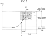
- FIG. 2 illustrates an example of a change with time of the accelerator pedal operation amount AP (accelerator opening degree [%]) when a driver performs the erroneous operation of the accelerator pedal (see a solid line L1), and an example of a change with time of the accelerator pedal operation amount AP when the driver intentionally operates the accelerator pedal (see a dashed line L2).
- a low opening degree region is, for example, a region in which the accelerator opening degree is 0% or more and less than 20%
- a middle opening degree region is, for example, a region in which the accelerator opening degree is 20% or more and less than 80%
- a high opening degree region is, for example, a region in which the accelerator opening degree is 80% or more.
- an amount of change in the accelerator pedal operation amount AP per unit time is referred to as an "accelerator pedal operation velocity (or accelerator opening degree speed) APV [%/s]".
- the accelerator pedal operation velocity APV is high in the middle opening degree region. For example, at a time point t0, the accelerator pedal operation velocity APV becomes equal to or higher than an operation velocity threshold APVth which is a positive value. Further, when a relatively short time (Tm1) has elapsed from the time point t0, the accelerator pedal operation amount AP reaches the high opening degree region. This is because the driver falls into a panic state and the driver depresses the accelerator pedal 51 strongly.
- Tm1 relatively short time
- the driver intentionally depresses the accelerator pedal 51 strongly.
- the accelerator pedal operation velocity APV is high in the middle opening degree region, and therefore, at the time point t0, the accelerator pedal operation velocity APV becomes equal to or higher than the operation velocity threshold APVth.
- the accelerator pedal operation velocity APV is slightly decreased. This is because, in the above-mentioned situation, the driver tends to strongly depress the accelerator pedal at first, but depress the accelerator pedal relatively slowly thereafter.
- the accelerator pedal operation amount AP reaches the high opening degree region.
- the accelerator pedal operation amount AP may not reach the high opening degree region.
- the first apparatus determines whether or not the accelerator pedal operation amount AP becomes equal to or larger than a positive first operation amount threshold APth1 within a predetermined first time threshold Tath from the time point at which the accelerator pedal operation velocity APV becomes equal to or higher than the positive operation velocity threshold APVth. When such a condition is satisfied, the first apparatus determines that the erroneous operation of the accelerator pedal is performed.
- the control ECU 10 acquires the accelerator pedal operation amount AP (accelerator opening degree [%]) through the engine ECU 20 each time a predetermined time (hereinafter referred to as a "first time Tp1" for the sake of convenience) elapses.
- the control ECU 10 determines whether or not a first condition is satisfied.
- the first condition is satisfied when the following condition A1 is satisfied.
- the accelerator pedal operation velocity APV becomes equal to or higher than the operation velocity threshold APVth.
- the operation velocity threshold APVth may be a value equal to or higher than 70[%/s].
- the operation velocity threshold APVth may be a value equal to or larger than 90[%/s].
- the operation velocity threshold APVth may be a value equal to or larger than 100[%/s].
- the positive operation velocity threshold APVth is 100[%/s].
- the control ECU 10 When the first condition is satisfied, the control ECU 10 starts measuring time with a timer T.
- the timer T is a timer for measuring an elapsed time Ta since at a time point at which the first condition is satisfied.
- the control ECU 10 determines whether or not a second condition is satisfied.
- the second condition is satisfied when both of the following conditions B1 and B2 are satisfied.
- the accelerator pedal operation amount AP becomes equal to or larger than the first operation amount threshold APth1.
- the first operation amount threshold APth1 is a value equal to or larger than a lower limit value (for example, accelerator opening degree 80[%]) of the high opening degree region.
- the first operation amount threshold APth1 may be a value equal to or larger than 90[%]. In the present example, the first operation amount threshold APth1 is 90[%].
- the elapsed time Ta at a time point at which the condition B1 is satisfied is equal to or shorter than the predetermined first time threshold Tath.
- the first time threshold Tath is a value equal to or shorter than 0.5s.
- the first time threshold Tath may be a value equal to or shorter than 0.3s. In the present example, the first time threshold Tath is 0.3s.
- the control ECU 10 determines that the erroneous operation of the accelerator pedal 51 is performed by the driver.
- first condition and second condition are collectively referred to as an "erroneous operation condition”.
- the control ECU 10 determines that the erroneous operation condition is satisfied, the control ECU 10 starts the driving force suppression control, in place of normal driving force control which has been executed up to that determination time point.
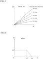
- the control ECU 10 is configured to, when the erroneous operation condition is not satisfied, execute the normal driving force control. Specifically, each time the first time elapses, the control ECU 10 applies the accelerator pedal operation amount AP and the vehicle speed Vs to a normal acceleration map M1(AP, Vs) illustrated in FIG. 3 to obtain a "required acceleration Gap corresponding to the accelerator pedal operation amount AP and the vehicle speed Vs".
- the required acceleration Gap is increased as the accelerator pedal operation amount AP is increased. Further, the required acceleration Gap is decreased as the vehicle speed Vs becomes higher.
- the control ECU 10 sets a target acceleration Gtgt to the required acceleration Gap, and transmits the set target acceleration Gtgt to the engine ECU 20.
- the engine ECU 20 controls the engine actuator 23 such that an actual acceleration Ga matches (becomes equal to) the target acceleration Gtgt.
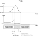
- the control ECU 10 is configured to, when the erroneous operation condition is satisfied, execute the driving force suppression control. Specifically, each time the first time elapses, the control ECU 10 obtains the required acceleration Gap through the use of the normal acceleration map M1(AP, Vs) in the same manner as the above-mentioned normal driving force control. Further, when the erroneous operation condition is satisfied, each time the first time elapses, the control ECU 10 applies the vehicle speed Vs to a limited acceleration map M2(Vs) illustrated in FIG. 4 to obtain an "upper limit acceleration Glim corresponding to the vehicle speed Vs".
- the upper limit acceleration Glim becomes a constant acceleration G1. Furthermore, the upper limit acceleration Glim is decreased as the vehicle speed Vs is increased from "Vs1". In addition, when the vehicle speed Vs is equal to or higher than "Vs2 (>Vs1)", the upper limit acceleration Glim becomes "0".
- the control ECU 10 sets the smaller of the required acceleration Gap and the upper limit acceleration Glim as the target acceleration Gtgt each time the first time elapses.
- the control ECU 10 transmits the set target acceleration Gtgt to the engine ECU 20.
- the engine ECU 20 controls the engine actuator 23 such that the actual acceleration Ga matches (becomes equal to) the target acceleration Gtgt.
- the first apparatus executes the driving force suppression control to thereby limit the target acceleration Gtgt to a value equal to or lower than the "upper limit acceleration Glim corresponding to the vehicle speed Vs". Therefore, when the driver performs the erroneous operation of the accelerator pedal 51, the first apparatus can control the driving force of the vehicle VA such that the actual acceleration Ga does not exceed the upper limit acceleration Glim. In other words, when the first apparatus determines that the erroneous operation condition is satisfied, the first apparatus controls the driving force of the vehicle VA such that the driving force (the value corresponding to the actual acceleration) of the vehicle VA changed according to the accelerator pedal operation amount AP is smaller than that of when the erroneous operation condition is not satisfied (that is, when executing the normal driving force control).
- the control ECU 10 determines whether or not a predetermined termination condition is satisfied on and after at the time point at which the driving force suppression control is started (that is, the erroneous operation condition is satisfied).
- the termination condition is satisfied when the erroneous operation of the accelerator pedal 51 is eliminated (cancelled).
- the termination condition is satisfied when the accelerator pedal operation amount AP becomes equal to or smaller than a predetermined termination threshold APeth.
- the termination threshold APeth is a value at which the accelerator pedal operation amount AP reaches when the driver weakens the operation on the accelerator pedal 51 (including when the driver releases his/her foot from the accelerator pedal).
- the termination threshold APeth may be, for example, a value in the low opening degree region (for example, the accelerator opening degree is 0 or more and less than 20[%]). In the present example, the termination threshold APeth is 10[%].
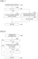
- the accelerator pedal operation velocity APV becomes equal to or higher than the operation velocity threshold APVth.
- the control ECU 10 performs the following operations 1 and 2.
- the accelerator pedal operation amount AP becomes equal to or larger than the first operation amount threshold APth1.
- the control ECU 10 performs the following operations 3 to 6.
- the erroneous operation of the accelerator pedal 51 is performed in a situation in which the vehicle speed Vs is low.
- the vehicle speed Vs is lower than Vs1 at the time point t2.
- the control ECU 10 uses the normal acceleration map M1(AP, Vs) to obtain the required acceleration Gap. Since the vehicle speed Vs is low and the accelerator pedal operation amount AP is large, the required acceleration Gap becomes larger. Further, the control ECU 10 uses the limited acceleration map M2(Vs) to obtain the upper limit acceleration Glim. In this case, the upper limit acceleration Glim is "G1", and is considerably smaller than the required acceleration Gap.
- control ECU 10 sets the target acceleration Gtgt to the upper limit acceleration Glim, and transmits the target acceleration Gtgt to the engine ECU 20.
- the travel state of the vehicle VA is controlled such that the actual acceleration Ga does not exceed the upper limit acceleration G1. Therefore, rapid acceleration of the vehicle VA is avoided.
- the driver weakens the operation on the accelerator pedal 51 in response to the alert processing. Thereafter, at the time point t3, the accelerator pedal operation amount AP becomes equal to or smaller than the termination threshold APeth, and therefore, the termination condition is satisfied.
- the control ECU 10 terminates the driving force suppression control, and restarts the normal driving force control.
- the CPU (hereinafter simply referred to as "CPU") of the control ECU 10 is configured to, each time a predetermined time (for example, the first time) elapses, execute routines illustrated in FIGs. 6 to 8 .
- the CPU receives detection signals and output signals from the sensors (11, 12, 21, 22 and 31) and the switches (13, 14 and 32) each time the first time elapses, and stores those detection signals and output signals in the RAM.
- Step 605 determines whether or not the operation switch 14 is in the on state.
- the CPU makes a "No" determination in Step 605, and proceeds directly to Step 695 to temporarily finish this routine.
- Step 605 the CPU makes a "Yes" determination in Step 605, and proceeds to Step 610 to determine whether or not a value of a suppression control execution flag (hereinafter simply referred to as an "execution flag") X1 is "0".
- execution flag X1 a suppression control execution flag
- the value of the execution flag X1 is "0"
- the value of the execution flag X1 is "1”
- the value of the execution flag X1 is set to "0" in an initialization routine to be executed by the CPU when an ignition switch (not shown) is changed from an off state to an on state.
- Step 610 When the value of the execution flag X1 is not "0", the CPU makes a "No" determination in Step 610, and proceeds directly to Step 695 to temporarily finish this routine.
- Step 610 When it is assumed that the value of the execution flag X1 is "0", the CPU makes a "Yes” determination in Step 610, and proceeds to Step 615 to determine whether or not the above-mentioned first condition is satisfied. When the first condition is not satisfied, the CPU makes a "No" determination in Step 615, and proceeds directly to Step 695 to temporarily finish this routine.
- Step 615 the CPU makes a "Yes" determination in Step 615, and proceeds to Step 620.
- Step 620 the CPU first resets/initializes the timer T. Then, the CPU starts measuring the elapsed time Ta by using the timer T.
- Step 625 the CPU determines whether or not the above-mentioned second condition is satisfied.
- Step 625 When the second condition is satisfied, the CPU makes a "Yes" determination in Step 625, and executes the processing of Steps 630 and 635 (described below) in sequence. Thereafter, the CPU proceeds to Step 695 to temporarily finish this routine.
- Step 625 the CPU makes a "No" determination in Step 625, and proceeds to Step 640 to determine whether or not the elapsed time Ta is longer than the first time threshold Tath.
- the CPU makes a "No" determination in Step 640, and returns to Step 625 to determine whether or not the second condition is satisfied.
- the CPU continues acquiring the latest information on the accelerator pedal operation amount AP from the accelerator pedal operation amount sensor 21.
- Step 640 the CPU makes a "Yes" determination in Step 640, and proceeds to Step 645 to end the measurement by the timer T. Thereafter, the CPU proceeds to Step 695 to temporarily finish this routine.
- Step 705 determines whether or not the value of the execution flag X1 is "0".
- the CPU makes a "Yes” determination in Step 705, and proceeds to Step 710.
- Step 710 the CPU executes the normal driving force control as described above. Thereafter, the CPU proceeds to Step 795 to temporarily finish this routine.
- Step 705 when the value of the execution flag X1 is not "0" (that is, the execution flag X1 is "1"), the CPU makes a "No" determination in Step 705, and executes the processing of Steps 715 and 720 (described below) in sequence. Thereafter, the CPU proceeds to Step 795 to temporarily finish this routine.
- Step 715 The CPU executes the driving force suppression control as described above.
- Step 720 The CPU executes the alerting processing for the driver. Specifically, the control ECU 10 causes the speaker 41 to utter the alert sound, and displays on the display 42 the above-mentioned message and mark for alerting the driver.
- Step 800 of FIG. 8 the CPU starts the processing from Step 800 of FIG. 8 , and proceeds to Step 805 to determine whether or not the value of the execution flag X1 is "1".
- Step 805 the CPU makes a "No" determination in Step 805, and proceeds directly to Step 895 to temporarily finish this routine.
- Step 805 When the value of the execution flag X1 is "1", the CPU makes a "Yes” determination in Step 805, and proceeds to Step 810 to determine whether or not the above-mentioned termination condition is satisfied. When the termination condition is not satisfied, the CPU makes a "No" determination in Step 810, and proceeds to Step 895 to temporarily finish this routine.
- Step 810 when the termination condition is satisfied, the CPU makes a "Yes" determination in Step 810, and proceeds to Step 815 to set the value of the execution flag X1 to "0". Therefore, the CPU makes a "Yes” determination in Step 705 in the routine of FIG. 7 .
- the driving force suppression control and the alerting processing are terminated, and the normal driving force control is restarted.
- the accelerator pedal operation amount AP tends to reach the high opening degree region in a relatively short time (within the first time threshold Tath) after the accelerator pedal operation velocity APV becomes large.
- the first apparatus determines the satisfaction of the first condition and the satisfaction of the second condition in a stepwise manner to thereby determine that the operation of the accelerator pedal 51 by the driver matches the above tendency.
- the first apparatus can distinguish between the erroneous operation of the accelerator pedal 51 and the intentional operation of the accelerator pedal 51 with high accuracy. Therefore, it is possible to reduce the possibility that the driving force suppression control is executed in a situation in which the driver intentionally operates the accelerator pedal 51 strongly. Further, the first apparatus can accurately determine the erroneous operation of the accelerator pedal 51 to thereby execute the driving force suppression control at an appropriate timing.
- the second apparatus differs from the first apparatus in that the first condition includes a condition A2 (operation amount condition) relating to the accelerator pedal operation amount AP in addition to the condition A1 (operation velocity condition).
- condition A2 operation amount condition
- condition A1 operation velocity condition
- the accelerator pedal operation velocity APV continues to be higher than a certain value.
- the accelerator pedal operation velocity APV is high even in a relatively high region APm in the middle opening degree region.
- the accelerator pedal operation velocity APV is slightly decreased. That is, after the accelerator pedal operation velocity APV is rapidly increased and thus reaches the region APm, the accelerator pedal operation velocity APV tends to be decreased. Therefore, when the accelerator pedal is intentionally operated, the possibility that the condition A1 is satisfied in the region APm is low.
- the second apparatus determines whether or not the condition A1 of the first condition is satisfied in the region APm in order to distinguish between the erroneous operation of the accelerator pedal 51 and the intentional operation of the accelerator pedal 51 with higher accuracy.
- the CPU of the control ECU 10 of the second apparatus is configured to execute a routine illustrated in FIG. 9 in place of the routine of FIG. 6 .
- the routine of FIG. 9 is a routine in which Step 615 in the routine of FIG. 6 is replaced with Step 910.
- steps in which the same processing as that in the steps illustrated in FIG. 6 is executed are indicated by the same reference numerals of FIG. 6 . Therefore, a detailed description is omitted for those steps.
- the CPU starts the processing from Step 900 in the routine of FIG. 9 each time a predetermined time (for example, the first time) elapses.
- a predetermined time for example, the first time
- the CPU proceeds to Step 910 to determine whether or not the first condition is satisfied.
- the CPU determines that the first condition is satisfied when the following conditions A1 and A2 are both satisfied.
- Step 910 When the first condition is not satisfied, the CPU makes a "No" determination in Step 910, and proceeds directly to Step 995 to temporarily finish this routine.
- Step 910 the CPU makes a "Yes" determination in Step 910, and executes the processing in appropriate steps from among Steps 620 to 645. Thereafter, the CPU proceeds to Step 995 to temporarily finish this routine.
- the second apparatus determines whether or not the condition A1 on the accelerator pedal operation velocity APV is satisfied in the relatively high region in the middle opening degree region (that is, the region in which the accelerator pedal operation amount AP is equal to or larger than the second operation amount threshold APth2, and smaller than the first operation amount threshold APth1). In other words, the second apparatus determines whether the accelerator pedal operation amount AP is equal to or larger than the second operation amount threshold APth2 at the time point at which the condition A1 is satisfied. Therefore, the second apparatus can distinguish between the erroneous operation of the accelerator pedal 51 and the intentional operation of the accelerator pedal 51 with higher accuracy.
- the third apparatus differs from the first apparatus in that the erroneous operation condition includes third to seventh conditions described later in addition to the first condition and the second condition.
- the erroneous operation condition includes third to seventh conditions described later in addition to the first condition and the second condition.
- a difference with the first apparatus will be mainly described.
- the control ECU 10 determines whether or not the following third condition is satisfied based on the signal from the brake switch 32.
- the elapsed time Tb is a period during which the off signal of the brake switch 32 continues from a time point at which the signal from the brake switch 32 is changed from the on signal to the off signal.
- the elapsed time Tb is a period during which a state where the driver does not operate the brake pedal 52 continues from a time point at which the driver releases his/her foot from the brake pedal 52.
- control ECU 10 sets the value of the elapsed time Tb to zero when the control ECU 10 receives the on signal from the brake switch 32. Then, the control ECU 10 starts measurement of the elapsed time Tb from a time point at which the control ECU 10 receives the off signal from the brake switch 32.
- this situation may be the following situation 1 or 2.
- the control ECU 10 determines whether or not the following fourth condition is satisfied based on the signal from the turn signal switch 13. (Fourth Condition): Both of the left and right turn signals 611 and 61r are in the off state.
- first state a state in which one of the left and right turn signals 611 and 61r is in the on state
- second state a state in which the left and right turn signals 611 and 61r are both in the off state
- off time point a time point at which the state of the left and right turn signals 611 and 61r is changed from the first state to the second state
- the driver intentionally operates the accelerator pedal 51 strongly.
- first condition and the second condition are satisfied in a situation in which a long time has elapsed since the off time point, there is a high possibility that the erroneous operation of the accelerator pedal 51 has been performed.
- control ECU 10 determines whether or not the following fifth condition is satisfied based on the signal from the turn signal switch 13.
- elapsed time Tc since the "off time point" is equal to or longer than a predetermined third time threshold Tcth.
- the elapsed time Tc refers to a period during which the second state of the left and right turn signals 611 and 61r is maintained from the off time point.
- control ECU 10 sets the value of the elapsed time Tc to zero when the control ECU 10 receives from the turn signal switch 13 the signal indicating that one of the left and right turn signals 611 and 61r is in the on state. Then, the control ECU 10 starts measurement of the elapsed time Tc from a time point at which the control ECU 10 receives from the turn signal switch 13 the signal indicating that the left and right turn signals 611 and 61r are both in the off state.
- the control ECU 10 determines whether or not the following sixth condition is satisfied.
- the vehicle speed Vs is equal to or lower than a predetermined vehicle speed threshold Vth.
- the vehicle speed threshold Vth is a value equal to or lower than 30[km/s]. In the present example, the vehicle speed threshold Vth is 30[km/s].
- the control ECU 10 determines whether or not the following seventh condition is satisfied based on the signal from the gradient sensor 12.
- the gradient Gr is equal to or smaller than a predetermined positive gradient threshold Grth.
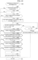
- the CPU of the control ECU 10 of the third apparatus is configured to execute a routine illustrated in FIG. 10 in place of the routine of FIG. 6 .
- the routine of FIG. 10 is a routine in which Steps 1010 to 1050 are added to the routine of FIG. 6 .
- steps in which the same processing as that in the steps illustrated in FIG. 6 is executed are indicated by the same reference numerals of FIG. 6 . Therefore, a detailed description is omitted for those steps.
- the CPU starts the processing from Step 1000 in the routine of FIG. 10 each time a predetermined time (for example, the first time) elapses.
- a predetermined time for example, the first time
- the CPU proceeds to Step 1010 to determine whether or not the above-mentioned third condition is satisfied.
- Step 1010 When the third condition is not satisfied, the CPU makes a "No" determination in Step 1010, and proceeds directly to Step 1095 to temporarily finish this routine. Meanwhile, when the third condition is satisfied, the CPU makes a "Yes" determination in Step 1010, and proceeds to Step 1020 to determine whether or not the above-mentioned fourth condition is satisfied.
- Step 1020 When the fourth condition is not satisfied, the CPU makes a "No" determination in Step 1020, and proceeds directly to Step 1095 to temporarily finish this routine. Meanwhile, when the fourth condition is satisfied, the CPU makes a "Yes" determination in Step 1020, and proceeds to Step 1030 to determine whether or not the above-mentioned fifth condition is satisfied.
- Step 1030 When the fifth condition is not satisfied, the CPU makes a "No" determination in Step 1030, and proceeds directly to Step 1095 to temporarily finish this routine. Meanwhile, when the fifth condition is satisfied, the CPU makes a "Yes" determination in Step 1030, and proceeds to Step 1040 to determine whether or not the above-mentioned sixth condition is satisfied.
- Step 1040 When the sixth condition is not satisfied, the CPU makes a "No" determination in Step 1040, and proceeds directly to Step 1095 to temporarily finish this routine. Meanwhile, when the sixth condition is satisfied, the CPU makes a "Yes" determination in Step 1040, and proceeds to Step 1050 to determine whether or not the above-mentioned seventh condition is satisfied.
- Step 1050 When the seventh condition is not satisfied, the CPU makes a "No" determination in Step 1050, and proceeds directly to Step 1095 to temporarily finish this routine. Meanwhile, when the seventh condition is satisfied, the CPU makes a "Yes" determination in Step 1050, and executes the processing of Steps 630 and 635 as described above. Thereafter, the CPU proceeds to Step 1095 to temporarily finish this routine.
- the erroneous operation condition used in the third apparatus includes the third to seventh conditions in addition to the first and second conditions. Therefore, the third apparatus can determine the erroneous operation of the accelerator pedal 51 with higher accuracy to thereby execute the driving force suppression control at an appropriate timing.
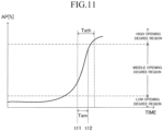
- the control ECU 10 calculates the accelerator pedal operation velocity APV at a time point t12 at which a predetermined time Tam ( ⁇ Tath) has elapsed since a time point t11 at which the first condition is satisfied.
- the predetermined time Tam is, for example, a value longer than "Tath/2".
- the control ECU 10 determines that the accelerator pedal operation amount AP will have reached the first operation amount threshold APth1 within the first time threshold Tath from the time point t11.
- the control ECU 10 may monitor the accelerator pedal operation velocity APV, and determine whether the second condition is satisfied at the time point t12 at which the predetermined time Tam has elapsed since the time point t11 at which the first condition is satisfied.
- Step 615 of FIG. 10 may be replaced with Step 910 of FIG. 9 .
- the timing for determining whether each of the third to seventh conditions is satisfied is not limited to the timing of the routine in FIG. 10 (that is, after Step 625).
- the CPU may determine whether each of the third to seventh conditions is satisfied at the timing at which the first condition is satisfied.
- Steps 1010 to 1050 may be inserted between Steps 615 and 620.
- the erroneous operation condition may not include all of the third to seventh conditions. In one or more embodiment, the erroneous operation condition may include at least one of the third to seventh conditions in addition to the first and second conditions. That is, one or more of Steps 1010 to 1050 may be omitted in FIG. 10 .
- the termination condition in Step 810 is not limited to the above example.
- the termination condition may be a condition satisfied when the control ECU 10 receives the on signal from the brake switch 32, or the brake pedal operation amount BP becomes a value larger than zero.
- the accelerator operation element is not limited to the accelerator pedal 51, and may be, for example, an accelerator lever.
- the decelerator operation element is not limited to the brake pedal 52, and may be, for example, a brake lever.
- the control ECU 10 may be configured to transmit the target acceleration Gtgt to the brake ECU 30 in Step 715 of FIG. 7 .
- the brake ECU 30 may be configured to, when the actual acceleration Ga exceeds the target acceleration Gtgt, control the brake actuator 33 to apply the braking force to the wheels.
- the travel state of the vehicle VA is controlled such that the actual acceleration Ga does not exceed the target acceleration Gtgt.
- the vehicle VA may include an inclination angle sensor configured to detect an inclination angle ⁇ of a road on which the vehicle VA travels, in place of the gradient sensor 12.
- the seventh condition may be a condition satisfied when the inclination angle ⁇ of the road is equal to or smaller than a predetermined positive inclination angle threshold ⁇ th.
- the driving force suppression control is not limited to the above example.
- the control ECU 10 when the erroneous operation condition is satisfied, the control ECU 10 is configured to control the driving force of the vehicle VA such that the driving force of the vehicle VA changed according to the accelerator pedal operation amount AP becomes smaller than that of when the erroneous operation condition is not satisfied (that is, when the normal driving force control is executed).
- control ECU 10 may always set the target acceleration Gtgt to zero.
- the control ECU 10 may calculate the target acceleration Gtgt by multiplying the required acceleration Gap corresponding to the accelerator pedal operation amount AP by a predetermined coefficient (for example, a value less than 1). According to this configuration, the driving force of the vehicle VA when the erroneous operation condition is satisfied becomes smaller than the driving force of when the erroneous operation condition is not satisfied (that is, when the normal driving force control is executed).
Landscapes
- Engineering & Computer Science (AREA)
- Automation & Control Theory (AREA)
- Transportation (AREA)
- Mechanical Engineering (AREA)
- Human Computer Interaction (AREA)
- Combustion & Propulsion (AREA)
- Chemical & Material Sciences (AREA)
- Mathematical Physics (AREA)
- Physics & Mathematics (AREA)
- Control Of Vehicle Engines Or Engines For Specific Uses (AREA)
- Control Of Driving Devices And Active Controlling Of Vehicle (AREA)
- Auxiliary Drives, Propulsion Controls, And Safety Devices (AREA)
- Control Of Throttle Valves Provided In The Intake System Or In The Exhaust System (AREA)
- Hybrid Electric Vehicles (AREA)
Applications Claiming Priority (2)
| Application Number | Priority Date | Filing Date | Title |
|---|---|---|---|
| JP2019147173A JP6806201B1 (ja) | 2019-08-09 | 2019-08-09 | 車両制御装置及び車両制御方法 |
| EP20171427.6A EP3786022B1 (de) | 2019-08-09 | 2020-04-24 | Vorrichtung und verfahren zur fahrzeugsteuerung |
Related Parent Applications (2)
| Application Number | Title | Priority Date | Filing Date |
|---|---|---|---|
| EP20171427.6A Division EP3786022B1 (de) | 2019-08-09 | 2020-04-24 | Vorrichtung und verfahren zur fahrzeugsteuerung |
| EP20171427.6A Division-Into EP3786022B1 (de) | 2019-08-09 | 2020-04-24 | Vorrichtung und verfahren zur fahrzeugsteuerung |
Publications (3)
| Publication Number | Publication Date |
|---|---|
| EP4403431A2 true EP4403431A2 (de) | 2024-07-24 |
| EP4403431A3 EP4403431A3 (de) | 2024-09-04 |
| EP4403431B1 EP4403431B1 (de) | 2025-11-26 |
Family
ID=70464928
Family Applications (2)
| Application Number | Title | Priority Date | Filing Date |
|---|---|---|---|
| EP20171427.6A Active EP3786022B1 (de) | 2019-08-09 | 2020-04-24 | Vorrichtung und verfahren zur fahrzeugsteuerung |
| EP24180374.1A Active EP4403431B1 (de) | 2019-08-09 | 2020-04-24 | Fahrzeugsteuerungsvorrichtung und -verfahren |
Family Applications Before (1)
| Application Number | Title | Priority Date | Filing Date |
|---|---|---|---|
| EP20171427.6A Active EP3786022B1 (de) | 2019-08-09 | 2020-04-24 | Vorrichtung und verfahren zur fahrzeugsteuerung |
Country Status (4)
| Country | Link |
|---|---|
| US (1) | US11511765B2 (de) |
| EP (2) | EP3786022B1 (de) |
| JP (1) | JP6806201B1 (de) |
| CN (1) | CN112339559B (de) |
Families Citing this family (12)
| Publication number | Priority date | Publication date | Assignee | Title |
|---|---|---|---|---|
| JP5787649B2 (ja) | 2010-10-26 | 2015-09-30 | 株式会社小糸製作所 | 車両用灯具の制御装置および車両用灯具システム |
| USRE49776E1 (en) | 2010-10-26 | 2024-01-02 | Koito Manufacturing Co., Ltd. | Vehicle lamp controller, vehicle lamp system, and vehicle lamp control method |
| JP6933245B2 (ja) * | 2019-12-25 | 2021-09-08 | トヨタ自動車株式会社 | 運転支援装置 |
| KR102869088B1 (ko) * | 2020-04-03 | 2025-10-14 | 현대자동차주식회사 | 운전자의 가속 페달 오조작 처리 장치 및 방법 |
| JP7343846B2 (ja) * | 2020-11-24 | 2023-09-13 | トヨタ自動車株式会社 | 車両制御装置及び車両制御方法 |
| JP7559777B2 (ja) | 2022-01-14 | 2024-10-02 | トヨタ自動車株式会社 | 加速抑制装置 |
| JP7509160B2 (ja) * | 2022-03-17 | 2024-07-02 | トヨタ自動車株式会社 | 車速制限装置、車速制限方法及び車速制限プログラム |
| JP7461982B2 (ja) * | 2022-03-28 | 2024-04-04 | 本田技研工業株式会社 | 急加速抑制装置及び急加速抑制制御方法 |
| KR20240003356A (ko) * | 2022-06-30 | 2024-01-09 | 현대자동차주식회사 | 전기자동차의 정차 저크 저감을 위한 제어 방법 |
| JP7421613B1 (ja) * | 2022-08-31 | 2024-01-24 | 本田技研工業株式会社 | 車両制御システム |
| JP2024042317A (ja) | 2022-09-15 | 2024-03-28 | トヨタ自動車株式会社 | 運転支援装置、運転支援方法、及び運転支援プログラム |
| JP2025030672A (ja) * | 2023-08-24 | 2025-03-07 | トヨタ自動車株式会社 | 車両制御装置及び車両制御方法 |
Citations (1)
| Publication number | Priority date | Publication date | Assignee | Title |
|---|---|---|---|---|
| JP2018131069A (ja) | 2017-02-15 | 2018-08-23 | 株式会社ミラリード | 急発進防止装置 |
Family Cites Families (15)
| Publication number | Priority date | Publication date | Assignee | Title |
|---|---|---|---|---|
| DE10344705B4 (de) * | 2003-09-26 | 2014-04-24 | Daimler Ag | Verfahren und Vorrichtung zur Verhinderung unbeabsichtigter Beschleunigungen eines Fahrzeugs |
| JP4396284B2 (ja) * | 2004-01-21 | 2010-01-13 | 日産自動車株式会社 | スロットル制御装置 |
| JP2011173586A (ja) * | 2010-01-27 | 2011-09-08 | Toshiko Takano | 自動車用アクセル誤操作による暴走防止装置 |
| US8280607B2 (en) * | 2010-07-01 | 2012-10-02 | GM Global Technology Operations LLC | Safely overriding unintended acceleration protection in vehicles towing trailers |
| JP2012107602A (ja) * | 2010-11-19 | 2012-06-07 | Autonetworks Technologies Ltd | 車両用運転制御装置 |
| JP2012121534A (ja) * | 2010-12-10 | 2012-06-28 | Daimler Ag | 車両の自動制動装置 |
| JP5282799B2 (ja) * | 2011-06-17 | 2013-09-04 | トヨタ自動車株式会社 | 車両の制御装置 |
| JP5854154B2 (ja) * | 2012-11-27 | 2016-02-09 | 日産自動車株式会社 | 加減速誤操作判定装置、誤操作加速抑制制御装置、加減速誤操作判定方法 |
| JP6082265B2 (ja) * | 2013-02-14 | 2017-02-15 | 富士重工業株式会社 | 運転支援制御装置 |
| JP6055334B2 (ja) * | 2013-02-14 | 2016-12-27 | 富士重工業株式会社 | アクセルペダルの誤操作制御装置 |
| JP2016013807A (ja) * | 2014-07-03 | 2016-01-28 | 本田技研工業株式会社 | 車両走行制御装置 |
| CN105667495B (zh) * | 2016-03-21 | 2019-01-11 | 福建省汽车工业集团云度新能源汽车股份有限公司 | 一种防误踩的电动汽车油门踏板控制方法及系统 |
| JP6772603B2 (ja) * | 2016-07-08 | 2020-10-21 | 三菱自動車工業株式会社 | 車両の誤発進抑制装置 |
| JP6968403B2 (ja) * | 2017-05-16 | 2021-11-17 | 株式会社ペルシード | アクセル信号制御装置およびアクセル信号制御方法 |
| CN108189668B (zh) * | 2018-02-12 | 2023-07-25 | 吉林大学 | 一种个性化智能加速踏板装置及其控制方法 |
-
2019
- 2019-08-09 JP JP2019147173A patent/JP6806201B1/ja active Active
-
2020
- 2020-04-24 EP EP20171427.6A patent/EP3786022B1/de active Active
- 2020-04-24 EP EP24180374.1A patent/EP4403431B1/de active Active
- 2020-05-27 US US16/884,282 patent/US11511765B2/en active Active
- 2020-08-04 CN CN202010771911.XA patent/CN112339559B/zh active Active
Patent Citations (1)
| Publication number | Priority date | Publication date | Assignee | Title |
|---|---|---|---|---|
| JP2018131069A (ja) | 2017-02-15 | 2018-08-23 | 株式会社ミラリード | 急発進防止装置 |
Also Published As
| Publication number | Publication date |
|---|---|
| US11511765B2 (en) | 2022-11-29 |
| JP2021028187A (ja) | 2021-02-25 |
| CN112339559B (zh) | 2024-04-05 |
| EP4403431B1 (de) | 2025-11-26 |
| JP6806201B1 (ja) | 2021-01-06 |
| CN112339559A (zh) | 2021-02-09 |
| EP3786022B1 (de) | 2024-07-17 |
| EP4403431A3 (de) | 2024-09-04 |
| US20210039665A1 (en) | 2021-02-11 |
| EP3786022A1 (de) | 2021-03-03 |
Similar Documents
| Publication | Publication Date | Title |
|---|---|---|
| EP4403431B1 (de) | Fahrzeugsteuerungsvorrichtung und -verfahren | |
| EP4005893B1 (de) | Fahrzeugsteuerungsvorrichtung und fahrzeugsteuerungsverfahren | |
| US8396641B2 (en) | Inter-vehicle distance control device | |
| US8406952B2 (en) | Electric parking brake control system and electric parking brake control method | |
| US11597401B2 (en) | Driving assistance apparatus for erroneous accelerator pedal operation | |
| US9818241B2 (en) | Malfunction diagnosing apparatus for vehicle | |
| JP7151755B2 (ja) | 誤操作判定装置 | |
| US11225254B2 (en) | Driving support device | |
| US11407425B2 (en) | Vehicle control device for executing a limit control for limiting a driving force of a vehicle | |
| US11040724B2 (en) | Vehicle driving force control apparatus | |
| CN109572669A (zh) | 驾驶辅助装置 | |
| CN103921648A (zh) | 车用空气调节器控制装置 | |
| CN111810338A (zh) | 滚动停止-起动系统的改进 | |
| US11912270B2 (en) | Vehicle driving assist apparatus | |
| US11279374B2 (en) | Driving force control apparatus | |
| US20250222927A1 (en) | Vehicle control device | |
| JP7596981B2 (ja) | 運転支援装置 | |
| JP2022015999A (ja) | 車両制御装置 | |
| JPH08318782A (ja) | 車両用制動報知装置 |
Legal Events
| Date | Code | Title | Description |
|---|---|---|---|
| PUAI | Public reference made under article 153(3) epc to a published international application that has entered the european phase |
Free format text: ORIGINAL CODE: 0009012 |
|
| STAA | Information on the status of an ep patent application or granted ep patent |
Free format text: STATUS: REQUEST FOR EXAMINATION WAS MADE |
|
| 17P | Request for examination filed |
Effective date: 20240606 |
|
| AC | Divisional application: reference to earlier application |
Ref document number: 3786022 Country of ref document: EP Kind code of ref document: P |
|
| AK | Designated contracting states |
Kind code of ref document: A2 Designated state(s): AL AT BE BG CH CY CZ DE DK EE ES FI FR GB GR HR HU IE IS IT LI LT LU LV MC MK MT NL NO PL PT RO RS SE SI SK SM TR |
|
| PUAL | Search report despatched |
Free format text: ORIGINAL CODE: 0009013 |
|
| AK | Designated contracting states |
Kind code of ref document: A3 Designated state(s): AL AT BE BG CH CY CZ DE DK EE ES FI FR GB GR HR HU IE IS IT LI LT LU LV MC MK MT NL NO PL PT RO RS SE SI SK SM TR |
|
| RIC1 | Information provided on ipc code assigned before grant |
Ipc: B60W 50/10 20120101AFI20240726BHEP |
|
| GRAP | Despatch of communication of intention to grant a patent |
Free format text: ORIGINAL CODE: EPIDOSNIGR1 |
|
| STAA | Information on the status of an ep patent application or granted ep patent |
Free format text: STATUS: GRANT OF PATENT IS INTENDED |
|
| INTG | Intention to grant announced |
Effective date: 20250709 |
|
| GRAS | Grant fee paid |
Free format text: ORIGINAL CODE: EPIDOSNIGR3 |
|
| GRAA | (expected) grant |
Free format text: ORIGINAL CODE: 0009210 |
|
| STAA | Information on the status of an ep patent application or granted ep patent |
Free format text: STATUS: THE PATENT HAS BEEN GRANTED |
|
| AC | Divisional application: reference to earlier application |
Ref document number: 3786022 Country of ref document: EP Kind code of ref document: P |
|
| AK | Designated contracting states |
Kind code of ref document: B1 Designated state(s): AL AT BE BG CH CY CZ DE DK EE ES FI FR GB GR HR HU IE IS IT LI LT LU LV MC MK MT NL NO PL PT RO RS SE SI SK SM TR |
|
| REG | Reference to a national code |
Ref country code: CH Ref legal event code: F10 Free format text: ST27 STATUS EVENT CODE: U-0-0-F10-F00 (AS PROVIDED BY THE NATIONAL OFFICE) Effective date: 20251126 Ref country code: GB Ref legal event code: FG4D |