EP4403244A1 - Feuchtigkeitsregelungsvorrichtung oder generator für atmosphärisches wasser - Google Patents
Feuchtigkeitsregelungsvorrichtung oder generator für atmosphärisches wasser Download PDFInfo
- Publication number
- EP4403244A1 EP4403244A1 EP22869928.6A EP22869928A EP4403244A1 EP 4403244 A1 EP4403244 A1 EP 4403244A1 EP 22869928 A EP22869928 A EP 22869928A EP 4403244 A1 EP4403244 A1 EP 4403244A1
- Authority
- EP
- European Patent Office
- Prior art keywords
- moisture
- air
- humidity control
- control apparatus
- water generator
- Prior art date
- Legal status (The legal status is an assumption and is not a legal conclusion. Google has not performed a legal analysis and makes no representation as to the accuracy of the status listed.)
- Pending
Links
Images


Classifications
-
- F—MECHANICAL ENGINEERING; LIGHTING; HEATING; WEAPONS; BLASTING
- F24—HEATING; RANGES; VENTILATING
- F24F—AIR-CONDITIONING; AIR-HUMIDIFICATION; VENTILATION; USE OF AIR CURRENTS FOR SCREENING
- F24F3/00—Air-conditioning systems in which conditioned primary air is supplied from one or more central stations to distributing units in the rooms or spaces where it may receive secondary treatment; Apparatus specially designed for such systems
- F24F3/12—Air-conditioning systems in which conditioned primary air is supplied from one or more central stations to distributing units in the rooms or spaces where it may receive secondary treatment; Apparatus specially designed for such systems characterised by the treatment of the air otherwise than by heating and cooling
- F24F3/14—Air-conditioning systems in which conditioned primary air is supplied from one or more central stations to distributing units in the rooms or spaces where it may receive secondary treatment; Apparatus specially designed for such systems characterised by the treatment of the air otherwise than by heating and cooling by humidification; by dehumidification
-
- B—PERFORMING OPERATIONS; TRANSPORTING
- B01—PHYSICAL OR CHEMICAL PROCESSES OR APPARATUS IN GENERAL
- B01D—SEPARATION
- B01D5/00—Condensation of vapours; Recovering volatile solvents by condensation
- B01D5/0057—Condensation of vapours; Recovering volatile solvents by condensation in combination with other processes
-
- B—PERFORMING OPERATIONS; TRANSPORTING
- B01—PHYSICAL OR CHEMICAL PROCESSES OR APPARATUS IN GENERAL
- B01D—SEPARATION
- B01D53/00—Separation of gases or vapours; Recovering vapours of volatile solvents from gases; Chemical or biological purification of waste gases, e.g. engine exhaust gases, smoke, fumes, flue gases, aerosols
- B01D53/02—Separation of gases or vapours; Recovering vapours of volatile solvents from gases; Chemical or biological purification of waste gases, e.g. engine exhaust gases, smoke, fumes, flue gases, aerosols by adsorption, e.g. preparative gas chromatography
- B01D53/04—Separation of gases or vapours; Recovering vapours of volatile solvents from gases; Chemical or biological purification of waste gases, e.g. engine exhaust gases, smoke, fumes, flue gases, aerosols by adsorption, e.g. preparative gas chromatography with stationary adsorbents
- B01D53/0407—Constructional details of adsorbing systems
- B01D53/0438—Cooling or heating systems
-
- B—PERFORMING OPERATIONS; TRANSPORTING
- B01—PHYSICAL OR CHEMICAL PROCESSES OR APPARATUS IN GENERAL
- B01D—SEPARATION
- B01D53/00—Separation of gases or vapours; Recovering vapours of volatile solvents from gases; Chemical or biological purification of waste gases, e.g. engine exhaust gases, smoke, fumes, flue gases, aerosols
- B01D53/02—Separation of gases or vapours; Recovering vapours of volatile solvents from gases; Chemical or biological purification of waste gases, e.g. engine exhaust gases, smoke, fumes, flue gases, aerosols by adsorption, e.g. preparative gas chromatography
- B01D53/06—Separation of gases or vapours; Recovering vapours of volatile solvents from gases; Chemical or biological purification of waste gases, e.g. engine exhaust gases, smoke, fumes, flue gases, aerosols by adsorption, e.g. preparative gas chromatography with moving adsorbents, e.g. rotating beds
-
- B—PERFORMING OPERATIONS; TRANSPORTING
- B01—PHYSICAL OR CHEMICAL PROCESSES OR APPARATUS IN GENERAL
- B01D—SEPARATION
- B01D53/00—Separation of gases or vapours; Recovering vapours of volatile solvents from gases; Chemical or biological purification of waste gases, e.g. engine exhaust gases, smoke, fumes, flue gases, aerosols
- B01D53/26—Drying gases or vapours
- B01D53/261—Drying gases or vapours by adsorption
-
- B—PERFORMING OPERATIONS; TRANSPORTING
- B01—PHYSICAL OR CHEMICAL PROCESSES OR APPARATUS IN GENERAL
- B01D—SEPARATION
- B01D53/00—Separation of gases or vapours; Recovering vapours of volatile solvents from gases; Chemical or biological purification of waste gases, e.g. engine exhaust gases, smoke, fumes, flue gases, aerosols
- B01D53/26—Drying gases or vapours
- B01D53/28—Selection of materials for use as drying agents
-
- B—PERFORMING OPERATIONS; TRANSPORTING
- B01—PHYSICAL OR CHEMICAL PROCESSES OR APPARATUS IN GENERAL
- B01J—CHEMICAL OR PHYSICAL PROCESSES, e.g. CATALYSIS OR COLLOID CHEMISTRY; THEIR RELEVANT APPARATUS
- B01J20/00—Solid sorbent compositions or filter aid compositions; Sorbents for chromatography; Processes for preparing, regenerating or reactivating thereof
- B01J20/22—Solid sorbent compositions or filter aid compositions; Sorbents for chromatography; Processes for preparing, regenerating or reactivating thereof comprising organic material
- B01J20/223—Solid sorbent compositions or filter aid compositions; Sorbents for chromatography; Processes for preparing, regenerating or reactivating thereof comprising organic material containing metals, e.g. organo-metallic compounds, coordination complexes
- B01J20/226—Coordination polymers, e.g. metal-organic frameworks [MOF], zeolitic imidazolate frameworks [ZIF]
-
- B—PERFORMING OPERATIONS; TRANSPORTING
- B01—PHYSICAL OR CHEMICAL PROCESSES OR APPARATUS IN GENERAL
- B01J—CHEMICAL OR PHYSICAL PROCESSES, e.g. CATALYSIS OR COLLOID CHEMISTRY; THEIR RELEVANT APPARATUS
- B01J20/00—Solid sorbent compositions or filter aid compositions; Sorbents for chromatography; Processes for preparing, regenerating or reactivating thereof
- B01J20/22—Solid sorbent compositions or filter aid compositions; Sorbents for chromatography; Processes for preparing, regenerating or reactivating thereof comprising organic material
- B01J20/26—Synthetic macromolecular compounds
-
- B—PERFORMING OPERATIONS; TRANSPORTING
- B01—PHYSICAL OR CHEMICAL PROCESSES OR APPARATUS IN GENERAL
- B01J—CHEMICAL OR PHYSICAL PROCESSES, e.g. CATALYSIS OR COLLOID CHEMISTRY; THEIR RELEVANT APPARATUS
- B01J20/00—Solid sorbent compositions or filter aid compositions; Sorbents for chromatography; Processes for preparing, regenerating or reactivating thereof
- B01J20/28—Solid sorbent compositions or filter aid compositions; Sorbents for chromatography; Processes for preparing, regenerating or reactivating thereof characterised by their form or physical properties
- B01J20/28014—Solid sorbent compositions or filter aid compositions; Sorbents for chromatography; Processes for preparing, regenerating or reactivating thereof characterised by their form or physical properties characterised by their form
- B01J20/28023—Fibres or filaments
-
- B—PERFORMING OPERATIONS; TRANSPORTING
- B01—PHYSICAL OR CHEMICAL PROCESSES OR APPARATUS IN GENERAL
- B01J—CHEMICAL OR PHYSICAL PROCESSES, e.g. CATALYSIS OR COLLOID CHEMISTRY; THEIR RELEVANT APPARATUS
- B01J20/00—Solid sorbent compositions or filter aid compositions; Sorbents for chromatography; Processes for preparing, regenerating or reactivating thereof
- B01J20/30—Processes for preparing, regenerating, or reactivating
- B01J20/34—Regenerating or reactivating
- B01J20/3483—Regenerating or reactivating by thermal treatment not covered by groups B01J20/3441 - B01J20/3475, e.g. by heating or cooling
-
- F—MECHANICAL ENGINEERING; LIGHTING; HEATING; WEAPONS; BLASTING
- F24—HEATING; RANGES; VENTILATING
- F24F—AIR-CONDITIONING; AIR-HUMIDIFICATION; VENTILATION; USE OF AIR CURRENTS FOR SCREENING
- F24F3/00—Air-conditioning systems in which conditioned primary air is supplied from one or more central stations to distributing units in the rooms or spaces where it may receive secondary treatment; Apparatus specially designed for such systems
- F24F3/12—Air-conditioning systems in which conditioned primary air is supplied from one or more central stations to distributing units in the rooms or spaces where it may receive secondary treatment; Apparatus specially designed for such systems characterised by the treatment of the air otherwise than by heating and cooling
- F24F3/14—Air-conditioning systems in which conditioned primary air is supplied from one or more central stations to distributing units in the rooms or spaces where it may receive secondary treatment; Apparatus specially designed for such systems characterised by the treatment of the air otherwise than by heating and cooling by humidification; by dehumidification
- F24F3/147—Air-conditioning systems in which conditioned primary air is supplied from one or more central stations to distributing units in the rooms or spaces where it may receive secondary treatment; Apparatus specially designed for such systems characterised by the treatment of the air otherwise than by heating and cooling by humidification; by dehumidification with both heat and humidity transfer between supplied and exhausted air
-
- F—MECHANICAL ENGINEERING; LIGHTING; HEATING; WEAPONS; BLASTING
- F24—HEATING; RANGES; VENTILATING
- F24F—AIR-CONDITIONING; AIR-HUMIDIFICATION; VENTILATION; USE OF AIR CURRENTS FOR SCREENING
- F24F6/00—Air-humidification, e.g. cooling by humidification
- F24F6/02—Air-humidification, e.g. cooling by humidification by evaporation of water in the air
- F24F6/08—Air-humidification, e.g. cooling by humidification by evaporation of water in the air using heated wet elements
-
- B—PERFORMING OPERATIONS; TRANSPORTING
- B01—PHYSICAL OR CHEMICAL PROCESSES OR APPARATUS IN GENERAL
- B01D—SEPARATION
- B01D2253/00—Adsorbents used in seperation treatment of gases and vapours
- B01D2253/20—Organic adsorbents
- B01D2253/204—Metal organic frameworks (MOF's)
-
- B—PERFORMING OPERATIONS; TRANSPORTING
- B01—PHYSICAL OR CHEMICAL PROCESSES OR APPARATUS IN GENERAL
- B01D—SEPARATION
- B01D2257/00—Components to be removed
- B01D2257/80—Water
Definitions
- the present disclosure relates to a humidity control apparatus or an atmospheric water generator.
- Patent Literature 1 As described in Patent Literature 1 ( WO 2018/118377 A ), an atmospheric water generator is known in which moisture in atmosphere is adsorbed by an adsorbent having a metal-organic framework, and the moisture desorbed from the adsorbent is condensed to obtain condensed water.
- the adsorbent having the metal-organic framework When the adsorbent having the metal-organic framework is heated to desorb moisture from the adsorbent, if a heat-resistant temperature of the adsorbent is low, there is a possibility that the adsorbent is damaged by heat.
- a humidity control apparatus or an atmospheric water generator includes an adsorbing unit and a heating unit.
- the adsorbing unit adsorbs moisture.
- the heating unit heats the adsorbing unit to desorb the moisture adsorbed by the adsorbing unit from the adsorbing unit.
- the adsorbing unit has a substrate and a metal-organic framework.
- the metal-organic framework includes a metal ion and an organic ligand.
- the substrate has a heat-resistant temperature of 150°C or higher.
- the humidity control apparatus or the atmospheric water generator prevents an adsorbent from being damaged by heating of the adsorbent for desorbing the adsorbed moisture from the adsorbent.
- a humidity control apparatus or an atmospheric water generator according to a second aspect is the humidity control apparatus or the atmospheric water generator according to the first aspect, in which the adsorbing unit includes the metal-organic framework including a zirconium ion as the metal ion and fumaric acid as the organic ligand, or the metal-organic framework including an aluminum ion as the metal ion and 3,5-pyrazole-dicarboxylic acid as the organic ligand.
- the humidity control apparatus or the atmospheric water generator prevents an adsorbent from being damaged by heating of the adsorbent for desorbing the adsorbed moisture from the adsorbent.
- a humidity control apparatus or an atmospheric water generator according to a third aspect is the humidity control apparatus or the atmospheric water generator according to the first or second aspect, in which a value obtained by multiplying a density of the metal-organic framework by 90% RH water content of the metal-organic framework is 430 L/m 3 or more.
- an adsorbent having a high moisture adsorption efficiency is used.
- a humidity control apparatus or an atmospheric water generator according to a fourth aspect is the humidity control apparatus or the atmospheric water generator according to any one of the first to third aspects, in which the substrate includes a heat-resistant fiber.
- an adsorbent having a high heat resistance is used.
- a humidity control apparatus or an atmospheric water generator according to a fifth aspect is the humidity control apparatus or the atmospheric water generator according to the fourth aspect, in which the heat-resistant fiber includes an aramid fiber.
- an adsorbent having a high heat resistance is used.
- a humidity control apparatus or an atmospheric water generator according to a sixth aspect is the humidity control apparatus or the atmospheric water generator according to the fourth aspect, in which the heat-resistant fiber includes a PBO fiber.
- an adsorbent having a high heat resistance is used.
- a humidity control apparatus or an atmospheric water generator according to a seventh aspect is the humidity control apparatus or the atmospheric water generator according to the fourth aspect, in which the heat-resistant fiber includes a glass fiber.
- an adsorbent having a high heat resistance is used.
- a humidity control apparatus or an atmospheric water generator according to an eighth aspect is the humidity control apparatus or the atmospheric water generator according to the fourth aspect, in which the heat-resistant fiber includes a carbon fiber.
- an adsorbent having a high heat resistance is used.
- a humidity control apparatus or an atmospheric water generator according to a ninth aspect is the humidity control apparatus or the atmospheric water generator according to any one of the first to eighth aspects, and further includes a supply unit that supplies a gas heated by passing through the heating unit to the adsorbing unit.
- a humidity control apparatus or an atmospheric water generator according to a 10 aspect is the humidity control apparatus or the atmospheric water generator according to any one of the first to ninth aspects, in which a content of the metal-organic framework per unit area of the adsorbing unit is 70 wt% or more.
- an adsorbent having a content of the metal-organic framework of a predetermined value or more is used.
- a humidity control apparatus or an atmospheric water generator according to an eleventh aspect is the humidity control apparatus or the atmospheric water generator according to any one of the first to tenth aspects, and further includes an adjuster that adjusts an amount of the moisture to be desorbed from the adsorbing unit.
- the humidity control apparatus or the atmospheric water generator can adjust an ability to desorb moisture from the adsorbent.
- a humidity control apparatus is the humidity control apparatus according to any one of the first to eleventh aspects, and further includes a humidifier that humidifies a target space by using the moisture desorbed from the adsorbing unit.
- the humidity control apparatus prevents the adsorbent from being damaged by heating of the adsorbent for desorbing the adsorbed moisture from the adsorbent.
- An atmospheric water generator is the atmospheric water generator according to any one of the first to eleventh aspects, and further includes a condensing unit that condenses the moisture desorbed from the adsorbing unit to obtain condensed water.
- the atmospheric water generator prevents the adsorbent from being damaged by heating of the adsorbent for desorbing the adsorbed moisture from the adsorbent.
- a humidity control apparatus 100 performs a humidifying operation of humidifying a target space S1.
- the target space S1 is a space in a room partitioned by, for example, a ceiling wall 91, a side wall 92, and a floor wall (not illustrated).
- the humidity control apparatus 100 introduces and humidifies outdoor air and releases the humidified air to the target space S1.
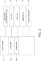
- the humidity control apparatus 100 includes a moisture absorbing rotor 11, a heater 12, a first fan 13, a second fan 14, a humidity sensor 15, a controller 16, a casing 17 accommodating the above devices, an air supply duct 18, and an exhaust duct 19.
- the casing 17 includes a casing body 21, a panel 22, an air supply connection pipe 23, and an air exhaust connection pipe 24.
- the casing body 21 is disposed in an attic space S2 formed above the ceiling wall 91. A lower end part of the casing body 21 penetrates the ceiling wall 91.
- the panel 22 is detachably attached to a lower surface of the casing body 21.
- the panel 22 is provided with a release port 25 that communicates an inside of the casing body 21 with the target space S1 and releases air from the casing body 21 to the target space S1.
- One end of the air supply connection pipe 23 and one end of the exhaust connection pipe 24 are disposed in the casing body 21.
- the other end of the air supply connection pipe 23 is an air supply port 26 for sucking outdoor air.
- the other end of the exhaust connection pipe 24 is an exhaust port 27 for exhausting air to outside.
- the air supply duct 18 serves as a first air supply duct that introduces outdoor air from the air supply port 26 into the first ventilation path P1 and a second air supply duct that introduces outdoor air from the air supply port 26 into the second ventilation path P2.
- One end of the exhaust duct 19 is connected to the exhaust connection pipe 24 of the casing 17.
- the other end of the exhaust duct 19 penetrates the side wall 92 and communicates with the outside.
- the air flowing through the first ventilation path P1 is exhausted from the exhaust port 27 to the outside through the exhaust duct 19.
- the moisture absorbing rotor 11 is disposed in a midway of the first ventilation path P1 and in a midway of the second ventilation path P2.
- the moisture absorbing rotor 11 is configured to remove moisture from the air flowing through the first ventilation path P1 and release the moisture to the air flowing through the second ventilation path P2 to humidify the air.
- the heater 12 is provided in a midway of the second ventilation path P2 and heats the air flowing through the second ventilation path P2.
- the first fan 13 is disposed near the exhaust port 27 in the first ventilation path P1 and generates an air flow in the first ventilation path P1. Specifically, the first fan 13 is disposed at a position where outdoor air can be introduced into the first ventilation path P1 through the air supply duct 18 and at a position where air deprived of moisture by the moisture absorbing rotor 11 can be exhausted to the outside through the exhaust duct 19.
- the second fan 14 is disposed near the release port 25 in the second ventilation path P2 and generates an air flow in the second ventilation path P2. Specifically, the second fan 14 is disposed at a position where outdoor air can be introduced into the second ventilation path P2 through the air supply duct 18 and at a position where air humidified by the moisture absorbing rotor 11 can be released to the target space S1 from the release port 25.
- the humidity sensor 15 is provided near the release port 25 in the casing body 21 and detects a humidity of the target space S1. A detection value of the humidity sensor 15 is output to the controller 16.
- the controller 16 is a computer such as a microcontroller.
- the controller 16 is hardware for implementing various functions by executing a predetermined program with predetermined data.
- the controller 16 controls the moisture absorbing rotor 11, the heater 12, the first fan 13, and the second fan 14 on the basis of the detection value of the humidity sensor 15 during the humidifying operation.
- outdoor air passes through the air supply duct 18 and is introduced into the first ventilation path P1 and the second ventilation path P2 of the casing body 21.
- Moisture in the air introduced into the first ventilation path P1 is deprived of by the moisture absorbing rotor 11, and the air deprived of the moisture passes through the exhaust duct 19 and is exhausted to the outside.
- the air introduced into the second ventilation path P2 is humidified by the moisture absorbing rotor 11, and the humidified air is released from the release port 25 to the target space S1.
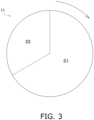
- the moisture absorbing rotor 11 has a disk shape and is configured to be rotatable about a center of the disk.
- the moisture absorbing rotor 11 includes a moisture absorbing material 11a formed in a substantially annular shape.
- the moisture absorbing rotor 11 is configured to allow air to pass in a thickness direction of the moisture absorbing rotor 11 to bring the passing air into contact with the moisture absorbing material 11a.
- a temperature of the moisture absorbing material 11a is low, the moisture absorbing material 11a adsorbs moisture from the air when the air passes through the moisture absorbing rotor 11.
- the moisture absorbing material 11a releases adsorbed moisture to the air when the air passes through the moisture absorbing rotor 11.
- the first region D1 is a region through which outdoor air introduced from the air supply port 26 passes.
- the moisture absorbing material 11a is cooled by the passing air and adsorbs moisture in the passing air. A portion of the moisture absorbing material 11a that has adsorbed moisture moves from the first region D1 to the second region D2.
- the second region D2 is a region through which the air passing through the first region D1 and heated by the heater 12 passes.
- the moisture absorbing material 11a is heated by the passing air and releases moisture to the passing air to humidify the air. A portion of the moisture absorbing material 11a that has released moisture moves from the second region D2 to the first region D1.
- the heater 12 is disposed downstream of the first region D1 and upstream of the second region D2 in the second ventilation path P2.
- the air having passed through the first region D1 is heated when passing through the heater 12.
- the air heated after passing through the heater 12 heats the moisture absorbing material 11a in the second region D2.
- the heater 12 indirectly heats the moisture absorbing material 11a in the second region D2, desorbs the moisture adsorbed by the moisture absorbing material 11a from the moisture absorbing material 11a, and regenerates the moisture absorbing material 11a.
- the second fan 14 generates an air flow in the second ventilation path P2 to supply the air heated by passing through the heater 12 to the moisture absorbing material 11a.
- the temperature of the moisture absorbing material 11a heated in the second region D2 is preferably from 100°C to 130°C. In this case, it is preferable that the temperature of the moisture absorbing material 11a does not locally exceed 250°C.
- the heater 12 may directly heat the moisture absorbing material 11a in the second region D2.
- the moisture absorbing material 11a may be heated by, for example, radiant heat of the heater 12.
- the controller 16 includes an adjuster 16a and a humidifier 16b.
- the adjuster 16a and the humidifier 16b each correspond to a function implemented by the controller 16 executing a predetermined program.
- the adjuster 16a adjusts the temperature of the moisture absorbing material 1 1a heated in the second region D2 by controlling output of the heater 12.
- the adjuster 16a adjusts the amount of moisture to be desorbed from the moisture absorbing material 11a.
- the humidifier 16b humidifies the target space S1 by using the moisture desorbed from the moisture absorbing material 11a such that the humidity of the target space S1 becomes a predetermined value.
- the humidifier 16b controls output of the second fan 14 to adjust a supply amount of the air humidified by passing through the moisture absorbing material 11a to the target space S1.
- the humidity of the target space S1 increases.
- the humidity of the target space S1 decreases.
- the humidifier 16b adjusts the humidity of the target space S1.
- the moisture absorbing material 11a is, for example, an adsorption element configured by carrying a metal-organic framework on a substrate formed in a honeycomb shape.
- the metal-organic framework is a porous material obtained by reaction of a metal ion with an organic ligand and having a significantly large specific surface area.
- the organic ligand is linked to the metal ion, and thus, a polymer structure having an infinite number of openings inside is obtained.
- An opening diameter and a topology of the metal-organic framework can be adjusted by selecting and combining a metal ion and an organic ligand.
- the opening diameter of the metal organic framework can be adjusted by selecting and combining a metal ion and an organic ligand, and the metal-organic framework can selectively adsorb a target.
- the metal-organic frameworks are used, for example, as porous materials having a function of selective storage and separation of molecules and ions.
- the metal-organic framework is used as adsorbent for adsorbing and desorbing moisture in air.
- the metal-organic framework can be synthesized by various methods.
- a solution method which is the simplest synthesis method, is a method of producing a metal-organic framework by mixing a metal salt and an organic ligand in a solution at normal temperature and normal pressure.
- the size of crystals to be produced can be controlled by adjusting a mixing rate.
- the metal-organic frameworks may be synthesized by any method selected from known methods such as a diffusion method, a hydrothermal method, a microwave method, an ultrasonic method, and a solid phase synthesis method.
- the performance of the metal-organic frameworks is measured with an effective adsorption amount.
- the effective adsorption amount is a mass of moisture that can be adsorbed and desorbed by the metal-organic framework having a unit mass (1 g) in one adsorption cycle.
- the moisture absorbing material 11a performs one adsorption process and one desorption process.
- the metal-organic framework used for the moisture absorbing material 11a is MOF-801 or MOF-303.
- MOF-801 is a metal-organic framework in which zirconium ions as metal ions are coordinated by fumaric acid as an organic ligand.
- MOF-303 is a metal-organic framework in which an aluminum ions as metal ions are coordinated by 3,5-pyrazole-dicarboxylic acid as an organic ligand.
- MOF-801 is represented by the following composition formula A-1.
- MOF-303 is represented by the following composition formula A-2.
- a content of the metal-organic framework per unit area of the moisture absorbing material 11a is preferably 70 wt% or more.
- a heat-resistant temperature of the substrate carrying the metal-organic framework is 150°C or higher.
- the heat-resistant temperature of the substrate is a temperature at which combustion or carbonization of the substrate starts in a process of heating the substrate.
- the substrate is, for example, paper or a fiber framework including heat-resistant fibers.
- the heat-resistant fiber is, for example, an aramid fiber, a PBO fiber, a glass fiber, or a carbon fiber.
- MOF-801 and MOF-303 the value obtained by multiplying the density by 90% RH water content is 430 L/m 3 or more, specifically 600 L/m 3 or more. Therefore, it has been confirmed that a moisture adsorption amount per unit volume of MOF-801 and MOF-303 is higher than a moisture adsorption amount per unit volume of zeolite. In other words, it has been confirmed that MOF-801 and MOF-303 is superior in moisture adsorption performance to zeolite.
- the above data are values obtained from results of performing moisture adsorption measurement under an environment at a temperature of 298 K and performing adsorption rate analysis and adsorption enthalpy analysis.
- heat resistance of MOF-801, MOF-303, and zeolite has been measured.
- the heat resistance has been measured by preparing a ⁇ 2 mm tablet as a sample and performing simultaneous thermogravimetry and differential thermal analysis (TG-DTA measurement) under the condition of heating from room temperature to 500°C in the air.
- TG-DTA measurement simultaneous thermogravimetry and differential thermal analysis
- MOF-801 and MOF-303 used for the moisture absorbing material 11a have the following characteristics as compared with zeolite (zeolite 13X) which is a conventional moisture adsorbent.
- MOF-801 and MOF-303 having a relatively low temperature at which adsorbed moisture is desorbed are used as the metal-organic frameworks carried by the substrate of the moisture absorbing material 11a. Specifically, when MOF-801 and MOF-303 that have adsorbed moisture are heated to around 100°C, the adsorbed moisture is desorbed and regenerated. In the humidity control apparatus 100, the heat-resistant temperature of the substrate of the moisture absorbing material 11a is 150°C or higher.
- the humidity control apparatus 100 since it is not necessary to heat the moisture absorbing material 11a to a temperature equal to or higher than the heat-resistant temperature of the substrate in order to desorb the adsorbed moisture from the moisture absorbing material 11a, damage or ignition of the moisture absorbing material 11a is suppressed.
- MOF-801 and MOF-303 having high heat resistance up to around 300°C are used as the metal-organic frameworks carried by the substrate of the moisture absorbing material 11a. Therefore, in the humidity control apparatus 100, damage or ignition of the moisture absorbing material 11a due to heating of the moisture absorbing material 11a for desorbing the adsorbed moisture from the moisture absorbing material 11a is suppressed.
- the moisture absorbing material 11a in which a value obtained by multiplying the density of the metal-organic framework carried by the substrate by 90% RH water content is 430 L/m 3 or more is used. Therefore, in the humidity control apparatus 100, since the metal-organic framework having a large moisture adsorption amount per unit volume is used for the adsorption element, the moisture adsorption performance of the moisture absorbing material 11a can be improved.
- the humidity control apparatus 100 can adjust an ability to desorb moisture from the moisture absorbing material 11a by adjusting the outputs of the heater 12 and the second fan 14. Therefore, the humidity control apparatus 100 can easily control the humidity of the target space S1 by adjusting the outputs of the heater 12 and the second fan 14.
- the heat-resistant temperature of the substrate of the moisture absorbing material 11a is 150°C or higher.
- the heat-resistant temperature of the substrate is preferably 300°C or higher.
- the heat-resistant temperature of the substrate is preferably 300°C or higher, which is an ignition point of the paper.
- the moisture absorbing material 11a is an adsorption element configured by carrying the metal-organic framework on the substrate formed in a honeycomb shape.
- the moisture absorbing material 11a may be a mixed paper produced by mixing paper pulp with a metal-organic framework and performing papermaking.
- the heat resistance of the mixed paper of this modification has been measured by performing simultaneous thermogravimetry and differential thermal analysis (TG-DTA measurement) under the condition of heating from room temperature to 500°C in the air.
- TG-DTA measurement thermogravimetry and differential thermal analysis
- combustion or carbonization of the mixed paper of this modification proceeds at 300°C or higher regardless of the type of paper, and the type and addition amount of the metal-organic framework.
- the mixed paper of this modification is regenerated by desorbing moisture from the metal-organic framework at around 100°C regardless of the type of paper and the type and addition amount of the metal-organic framework when moisture is adsorbed.
- zeolite 13X zeolite that has adsorbed moisture desorbs moisture and does not regenerate unless heated to around 250°C. Therefore, it has been confirmed that the mixed paper of this modification can be used as the moisture absorbing material 11a, and is superior in moisture adsorption performance and regeneration performance at a low temperature (around 100°C) to zeolite. Furthermore, it has been confirmed that even when the mixed paper of this modification is heated at a temperature of 110°C to 170°C for six hours, the combustion or carbonization of the mixed paper does not progress, and the regeneration performance of the mixed paper does not deteriorate.
- the humidity control apparatus 100 performs a humidifying operation of humidifying the target space S1.
- the humidity control apparatus 100 may perform a ventilation operation of exchanging the air in the target space S1 or a dehumidifying operation of dehumidifying the target space S1 instead of or in addition to the humidifying operation.
- the moisture absorbing material 11a according to the embodiment may be used in an apparatus other than the humidity control apparatus 100.
- an atmospheric water generator 200 which is another usage example of the moisture absorbing material 11a will be described.
- the atmospheric water generator 200 of this modification produces water by passing heated air through an adsorbent that adsorbs moisture in the air and cooling the obtained moist air to generate condensed water.
- the first air is sucked from atmosphere by the first fan 33, sequentially passes through the condenser 35 and the moisture absorbing material 31a in the first region D1, and then is exhausted to the atmosphere.
- the condenser 35 is disposed upstream of the moisture absorbing material 31a.
- the second air is sucked by the second fan 34 and circulates while sequentially passing through the heater 32, the moisture absorbing material 31a in the second region D2, and the condenser 35.
- the heater 32 for heating the dry second air is disposed upstream of the moisture absorbing material 31a, and a condenser 35 for cooling and condensing the wet second air is disposed downstream of the moisture absorbing material 31a.
- the first air sucked into the first ventilation path R1 by the first fan 33 passes through the condenser 35 and then passes through the moisture absorbing rotor 31. At this time, moisture included in the first air is adsorbed by the moisture absorbing material 31a in the first region D1. The first air having passed through the moisture absorbing rotor 31 is exhausted to the atmosphere. A portion of the moisture absorbing material 31a that has adsorbed moisture moves from the first region D1 to the second region D2.
- the second air circulating through the second ventilation path R2 by the second fan 34 is heated by the heater 32 and passes through the moisture absorbing rotor 31. At this time, moisture is desorbed from the moisture absorbing material 31a in the second region D2 by the heated second air. A portion of the moisture absorbing material 31a that has released moisture moves from the second region D2 to the first region D1.
- the second air having passed through the moisture absorbing rotor 31 becomes moist air including moisture desorbed from the moisture absorbing material 31a. Thereafter, the second air exchanges heat with the first air in the condenser 35. As a result, the second air is cooled and condensed, and consequently, condensed water is obtained in the condenser 35.
- the condensed water is stored in the water storage tank 37 disposed below the condenser 35.
- the condenser 35 includes, for example, a pipe through which the second air after passing through the moisture absorbing rotor 31 flows and a pipe through which the first air before passing through the moisture absorbing rotor 31 flows. In this case, flow directions of the first air and the second air may be countercurrent or cocurrent.
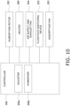
- the controller 36 is a computer such as a microcontroller. As illustrated in FIG. 5 , the controller 36 controls the moisture absorbing rotor 31, the heater 32, the first fan 33, and the second fan 34.
- the controller 36 includes an adjuster 36a and a water generation unit 36b.
- the adjuster 36a and the water generation unit 36b each correspond to a function implemented by the controller 16 executing a predetermined program.
- the adjuster 36a adjusts the temperature of the moisture absorbing material 3 1a heated in the second region D2 by controlling output of the heater 32.
- the adjuster 36a adjusts the amount of moisture to be desorbed from the moisture absorbing material 31a.
- the water generation unit 36b controls output of the second fan 34 to adjust the amount of condensed water generated in the condenser 35.
- a generation amount of condensed water increases.
- the generation amount of condensed water decreases.
- the water generation unit 36b can adjust the generation amount of the condensed water on the basis of, for example, a detection value of a water level sensor (not illustrated) that detects an amount of water stored in the water storage tank 37 so that the amount of water stored in the water storage tank 37 can fall within a predetermined range.
- the moisture absorbing material 11a according to the embodiment may be used in an apparatus other than the humidity control apparatus 100.
- an air conditioner 300 which is another usage example of the moisture absorbing material 11a will be described with reference to FIGS. 6 to 9 .
- the air conditioner 300 is a pair type air conditioner in which one outdoor unit 311 and one indoor unit 312 are connected to each other via a liquid refrigerant pipe 317, a gas refrigerant pipe 318, and an air supply and exhaust duct 315.
- the air conditioner 300 includes a refrigerant circuit 310 configured by connecting the outdoor unit 311 and the indoor unit 312 via the gas refrigerant pipe 318 and the liquid refrigerant pipe 317.
- the air supply and exhaust duct 315 connects a humidifying unit 350 and the indoor unit 312 in the outdoor unit 311.
- An indoor end of the air supply and exhaust duct 315 communicates with a portion downstream of the air intake port 316a and upstream of the indoor heat exchanger 313 in an air flow formed by the indoor fan 314 in the internal space of the indoor unit casing 316.
- the outdoor air conditioning unit 320 is connected to the indoor unit 312 via the liquid refrigerant pipe 317 and the gas refrigerant pipe 318.
- the liquid refrigerant pipe 317 is connected to one end of the indoor heat exchanger 313 in the indoor unit 312.
- the gas refrigerant pipe 318 is connected to the other end of the indoor heat exchanger 313 in the indoor unit 312.
- a second moisture absorption intake port 351c and an air supply and exhaust port 351d including a plurality of slit-shaped openings are provided on a back surface of the humidifying unit casing 351.
- the second moisture absorption intake port 351c is an opening through which air taken in from outdoors outside of the humidifying unit casing 351 passes in order to supply the outdoor air including moisture to the adsorption region X of the humidifying rotor 352.
- the air supply and exhaust port 351d is an opening for taking outdoor air into a humidifying flow path 358b during the humidifying operation or the air-supplying operation.
- the outdoor air flowing into the humidifying flow path 358b is heated by the heater 360 after passing through a cooling region Z as a part of the humidifying rotor 352.
- the air heated by the heater 360 passes through a heating region Y as another part of the humidifying rotor 352 and flows toward the air supply and exhaust fan 354.
- the air taken in from the indoor unit 312 and flowing through the air supply and exhaust duct 315 flows into the humidifying flow path 358b in the humidifying unit 350 and is discharged to outdoors through the air supply and exhaust port 351d.
- the adsorption fan 355 is rotationally driven by an adsorption fan motor, and generates an air flow passing through the adsorption region X that does not face the heater 360 in the humidifying rotor 352. Specifically, the adsorption fan 355 generates an air flow sucked from the first moisture absorption intake port 351b and the second moisture absorption intake port 351c, flowing through the moisture absorption flow path 358a, and exhausted to outdoors from the moisture absorption blow-out port 351a.
- the heater 360 includes a plurality of electric heating wires as heating elements. The air passing through the heater 360 is heated by the electric heating wire.
- the heater 360 has a function similar to the heater 12 according to the embodiment.
- the air supply and exhaust fan 354 causes the outdoor air to flow into the humidifying flow path 358b from the air supply and exhaust port 351d and pass through the humidifying rotor 352, and then generates an air flow flowing to the indoor unit 312 through the flow path switching device 353 and the air supply and exhaust duct 315 as indicated by an arrow A1.
- the air supply and exhaust fan 354 When indoor air is exhausted from the indoor unit 312 to outdoors, the air supply and exhaust fan 354 generates an air flow flowing from the indoor unit 312 to the air supply and exhaust duct 315 and from the air supply and exhaust port 351d to outdoors through the humidifying flow path 358b as indicated by an arrow A2.
- an air flow from the humidifying flow path 358b to the air supply and exhaust duct 315 or an air flow from the air supply and exhaust duct 315 to the humidifying flow path 358b is allowed. Therefore, in the supply state, it is possible to switch between a state in which the air flowing through the humidifying flow path 358b and blown out from the air supply and exhaust fan 354 flows in A1 direction in the air supply and exhaust duct 315 and a state in which the air passing through the air supply and exhaust duct 315 from the indoor unit 312 in A2 direction and sucked into the air supply and exhaust fan 354 is sent to the humidifying flow path 358b.
- the air taken in from the first moisture absorption intake port 351b and the second moisture absorption intake port 351c and flowing in the direction of arrow A11 passes through the adsorption region X of the humidifying rotor 352 from below to above, and then flows toward near above the bell mouth 357.
- the moisture included in the air taken in from the first moisture absorption intake port 351b and the second moisture absorption intake port 351c as described above is adsorbed by the humidifying rotor 352 when passing through the adsorption region X of the humidifying rotor 352.
- the air taken in from the air supply and exhaust port 351d and flowing in the direction of arrow A21 passes through the cooling region Z of the humidifying rotor 352 from below to above and is directed to the heater 360.
- the humidifying rotor 352 is cooled by being supplied with outdoor air. Apart of the moisture included in the air passing through the cooling region Z of the humidifying rotor 352 can be adsorbed in the cooling region Z.
- the air heated by the heater 360 passes through the heating region Y of the humidifying rotor 352 from above to below as air flowing in the direction of arrow A22-23, and is directed to the flow path switching device 353.
- the air heated by the heater 360 desorbs moisture adsorbed by the humidifying rotor 352 to become humidified air.
- the humidified air that has reached the flow path switching device 353 is returned to the flow path switching device 353 through the air supply and exhaust fan 354, and is sent to the indoor unit 312 through the air supply and exhaust duct 315.
- the indoor space is thus humidified.
- the compressor 321 is driven in a state in which the four-way switching valve 322 is switched so that the indoor heat exchanger 313 functions as an evaporator of the refrigerant in the refrigerant circuit 310 and the outdoor heat exchanger 324 functions as a condenser of the refrigerant.
- the cooling operation of cooling the indoor air can be performed.
- the indoor fan 314 and the outdoor fan 329 are driven and controlled.
- the compressor 321 is driven in a state in which the four-way switching valve 322 is switched so that the indoor heat exchanger 313 functions as a condenser of the refrigerant in the refrigerant circuit 310 and the outdoor heat exchanger 324 functions as an evaporator of the refrigerant.
- the heating operation of heating the indoor air can be performed.
- the indoor fan 314 and the outdoor fan 329 are driven and controlled.
- the humidifier 356b humidifies the indoor space by using the moisture desorbed from the moisture absorbing material 352a such that the humidity of the indoor space becomes a predetermined value.
- the humidifier 356b controls output of the air supply and exhaust fan 354 to adjust a supply amount of the air humidified by passing through the humidifying rotor 352 to the indoor space.
- the humidifier 356b adjusts the humidity of the indoor space.
- the outdoor air conditioning unit 320 may include a member corresponding to the controller 356.
- the air conditioner 300 can increase the humidity in the indoor space and reduce the humidity in the indoor space. Accordingly, the humidity in the indoor space can be adjusted.
- a degree of humidification can be adjusted by adjusting a heating degree of the heater 360 and an air blowing amount of the air supply and exhaust fan 354.
- the heating degree of the heater 360 is increased, since the heat-resistant temperature of the substrate of the moisture absorbing material 352a of the humidifying rotor 352 is high, and the heat resistance of the metal-organic framework carried by the substrate of the moisture absorbing material 352a is high, deterioration of the rotor and deterioration of the moisture absorption and desorption performance are suppressed.
Landscapes
- Chemical & Material Sciences (AREA)
- Chemical Kinetics & Catalysis (AREA)
- Analytical Chemistry (AREA)
- Engineering & Computer Science (AREA)
- Organic Chemistry (AREA)
- General Chemical & Material Sciences (AREA)
- Oil, Petroleum & Natural Gas (AREA)
- Combustion & Propulsion (AREA)
- Mechanical Engineering (AREA)
- General Engineering & Computer Science (AREA)
- Inorganic Chemistry (AREA)
- Thermal Sciences (AREA)
- Physics & Mathematics (AREA)
- Drying Of Gases (AREA)
- Solid-Sorbent Or Filter-Aiding Compositions (AREA)
- Central Air Conditioning (AREA)
- Air Humidification (AREA)
- Separation Of Gases By Adsorption (AREA)
Applications Claiming Priority (2)
| Application Number | Priority Date | Filing Date | Title |
|---|---|---|---|
| JP2021152259A JP2023044300A (ja) | 2021-09-17 | 2021-09-17 | 調湿装置または大気造水機 |
| PCT/JP2022/034028 WO2023042781A1 (ja) | 2021-09-17 | 2022-09-12 | 調湿装置または大気造水機 |
Publications (3)
| Publication Number | Publication Date |
|---|---|
| EP4403244A1 true EP4403244A1 (de) | 2024-07-24 |
| EP4403244A8 EP4403244A8 (de) | 2024-08-28 |
| EP4403244A4 EP4403244A4 (de) | 2025-08-20 |
Family
ID=85602866
Family Applications (1)
| Application Number | Title | Priority Date | Filing Date |
|---|---|---|---|
| EP22869928.6A Pending EP4403244A4 (de) | 2021-09-17 | 2022-09-12 | Feuchtigkeitsregelungsvorrichtung oder generator für atmosphärisches wasser |
Country Status (5)
| Country | Link |
|---|---|
| US (1) | US20240219043A1 (de) |
| EP (1) | EP4403244A4 (de) |
| JP (1) | JP2023044300A (de) |
| CN (1) | CN117940203A (de) |
| WO (1) | WO2023042781A1 (de) |
Families Citing this family (3)
| Publication number | Priority date | Publication date | Assignee | Title |
|---|---|---|---|---|
| JP6974771B2 (ja) * | 2020-03-16 | 2021-12-01 | ダイキン工業株式会社 | 加湿ユニット |
| WO2025144833A1 (en) * | 2023-12-26 | 2025-07-03 | Embrient, Inc. | Incubator with humidity control |
| WO2025203430A1 (ja) * | 2024-03-28 | 2025-10-02 | 三菱電機株式会社 | 空調装置及びそのドレン水処理部材 |
Family Cites Families (11)
| Publication number | Priority date | Publication date | Assignee | Title |
|---|---|---|---|---|
| JP2001004172A (ja) * | 1999-06-23 | 2001-01-12 | Mitsubishi Heavy Ind Ltd | 空気調和機用ロータ及び空気調和機 |
| JP4844514B2 (ja) * | 2007-09-11 | 2011-12-28 | 富士電機株式会社 | 調湿装置 |
| US10105824B2 (en) * | 2013-12-30 | 2018-10-23 | Smith International, Inc. | Chemical leaching/thermal decomposing carbonate in carbonate PCD |
| WO2018118377A1 (en) * | 2016-12-20 | 2018-06-28 | Massachusetts Institute Of Technology | Sorption-based atmospheric water harvesting device |
| JP7627117B2 (ja) * | 2018-03-14 | 2025-02-05 | デシカント・ローターズ・インターナショナル・プライヴェート・リミテッド | 有機金属構造体(mof)、共有結合性有機構造体(cof)、及びゼオライトイミダゾレート構造体(zif)をインサイチュ合成するための方法、並びにそれらの用途 |
| IL274932B2 (en) * | 2018-08-16 | 2023-12-01 | Commw Scient Ind Res Org | Metal organic framework based water capture apparatus |
| US11045785B2 (en) * | 2018-11-05 | 2021-06-29 | Industrial Technology Research Institute | Metal-organic framework, method for preparing the same, and adsorption device employing the same |
| US11859863B2 (en) * | 2019-08-16 | 2024-01-02 | Battelle Memorial Institute | Method and system for dehumidification and atmospheric water extraction with minimal energy consumption |
| JP6849035B1 (ja) * | 2019-09-30 | 2021-03-24 | ダイキン工業株式会社 | 加湿ユニット |
| JP7104339B2 (ja) * | 2020-03-31 | 2022-07-21 | ダイキン工業株式会社 | 空気質の調整システム |
| CN112755965B (zh) * | 2021-02-25 | 2023-07-21 | 北京工业大学 | 一种由mof材料和氯化锂的复合除湿吸附剂纸片的制备方法 |
-
2021
- 2021-09-17 JP JP2021152259A patent/JP2023044300A/ja active Pending
-
2022
- 2022-09-12 WO PCT/JP2022/034028 patent/WO2023042781A1/ja not_active Ceased
- 2022-09-12 CN CN202280062633.8A patent/CN117940203A/zh active Pending
- 2022-09-12 EP EP22869928.6A patent/EP4403244A4/de active Pending
-
2024
- 2024-03-15 US US18/606,389 patent/US20240219043A1/en active Pending
Also Published As
| Publication number | Publication date |
|---|---|
| EP4403244A4 (de) | 2025-08-20 |
| WO2023042781A1 (ja) | 2023-03-23 |
| EP4403244A8 (de) | 2024-08-28 |
| CN117940203A (zh) | 2024-04-26 |
| JP2023044300A (ja) | 2023-03-30 |
| US20240219043A1 (en) | 2024-07-04 |
Similar Documents
| Publication | Publication Date | Title |
|---|---|---|
| EP4403244A1 (de) | Feuchtigkeitsregelungsvorrichtung oder generator für atmosphärisches wasser | |
| JP4337402B2 (ja) | 空気調和機、空気調和機の運転方法 | |
| JP7464868B2 (ja) | 空気質の調整システム | |
| JPH11262621A (ja) | 除湿空調装置 | |
| US20100257884A1 (en) | Humidity control apparatus | |
| JPH11197439A (ja) | 除湿空調装置 | |
| WO2005036062A1 (ja) | 空気調和装置 | |
| JP2008249211A (ja) | 空気調和機 | |
| KR20060067795A (ko) | 제가습 장치 | |
| WO2010029710A1 (ja) | 空気調和機 | |
| JP2002235933A (ja) | 空気調和機 | |
| JP4258930B2 (ja) | 除加湿装置、除加湿機及び空気調和機 | |
| JP5104971B2 (ja) | 調湿換気装置 | |
| JP7633569B2 (ja) | 加湿装置および空気調和装置 | |
| CN103429963B (zh) | 换气系统 | |
| JP2010117112A (ja) | 空気調和機 | |
| JP2015055391A (ja) | 空気調和機 | |
| JP7617460B2 (ja) | 空気調和システム | |
| JP4161495B2 (ja) | 吸着式空調装置 | |
| JP2964843B2 (ja) | 空質調節機 | |
| WO2023209896A1 (ja) | 空調システム、湿式調湿ユニット及び空調方法 | |
| JP2002071172A (ja) | 加湿装置 | |
| JP2001311537A (ja) | 調湿装置 | |
| JP2001162131A (ja) | 吸着式空調装置 | |
| JP7820646B2 (ja) | 空気調和装置 |
Legal Events
| Date | Code | Title | Description |
|---|---|---|---|
| STAA | Information on the status of an ep patent application or granted ep patent |
Free format text: STATUS: THE INTERNATIONAL PUBLICATION HAS BEEN MADE |
|
| PUAI | Public reference made under article 153(3) epc to a published international application that has entered the european phase |
Free format text: ORIGINAL CODE: 0009012 |
|
| STAA | Information on the status of an ep patent application or granted ep patent |
Free format text: STATUS: REQUEST FOR EXAMINATION WAS MADE |
|
| 17P | Request for examination filed |
Effective date: 20240410 |
|
| AK | Designated contracting states |
Kind code of ref document: A1 Designated state(s): AL AT BE BG CH CY CZ DE DK EE ES FI FR GB GR HR HU IE IS IT LI LT LU LV MC MK MT NL NO PL PT RO RS SE SI SK SM TR |
|
| RIN1 | Information on inventor provided before grant (corrected) |
Inventor name: OKUZAWA, KENTO Inventor name: KIZAWA, TOSHIHIRO |
|
| DAV | Request for validation of the european patent (deleted) | ||
| DAX | Request for extension of the european patent (deleted) | ||
| P01 | Opt-out of the competence of the unified patent court (upc) registered |
Free format text: CASE NUMBER: APP_1021/2025 Effective date: 20250108 |
|
| RIC1 | Information provided on ipc code assigned before grant |
Ipc: B01J 20/28 20060101ALI20250417BHEP Ipc: B01J 20/22 20060101ALI20250417BHEP Ipc: B01D 53/28 20060101ALI20250417BHEP Ipc: B01D 53/04 20060101ALI20250417BHEP Ipc: F24F 3/147 20060101ALI20250417BHEP Ipc: B01D 3/28 20060101ALI20250417BHEP Ipc: B01D 53/02 20060101ALI20250417BHEP Ipc: E03B 3/28 20060101ALI20250417BHEP Ipc: B01J 20/34 20060101ALI20250417BHEP Ipc: B01J 20/26 20060101ALI20250417BHEP Ipc: F24F 3/14 20060101ALI20250417BHEP Ipc: F24F 6/08 20060101ALI20250417BHEP Ipc: B01D 53/26 20060101ALI20250417BHEP Ipc: B01D 53/06 20060101AFI20250417BHEP |
|
| A4 | Supplementary search report drawn up and despatched |
Effective date: 20250721 |
|
| RIC1 | Information provided on ipc code assigned before grant |
Ipc: B01D 53/06 20060101AFI20250715BHEP Ipc: B01D 53/26 20060101ALI20250715BHEP Ipc: F24F 6/08 20060101ALI20250715BHEP Ipc: F24F 3/14 20060101ALI20250715BHEP Ipc: B01J 20/26 20060101ALI20250715BHEP Ipc: B01J 20/34 20060101ALI20250715BHEP Ipc: E03B 3/28 20060101ALI20250715BHEP Ipc: B01D 53/02 20060101ALI20250715BHEP Ipc: B01D 3/28 20060101ALI20250715BHEP Ipc: F24F 3/147 20060101ALI20250715BHEP Ipc: B01D 53/04 20060101ALI20250715BHEP Ipc: B01D 53/28 20060101ALI20250715BHEP Ipc: B01J 20/22 20060101ALI20250715BHEP Ipc: B01J 20/28 20060101ALI20250715BHEP |
|
| STAA | Information on the status of an ep patent application or granted ep patent |
Free format text: STATUS: EXAMINATION IS IN PROGRESS |