EP4375472B1 - Tür, insbesondere haustür, und verfahren zur herstellung eines türflügels für eine solche tür - Google Patents
Tür, insbesondere haustür, und verfahren zur herstellung eines türflügels für eine solche tür Download PDFInfo
- Publication number
- EP4375472B1 EP4375472B1 EP23204993.2A EP23204993A EP4375472B1 EP 4375472 B1 EP4375472 B1 EP 4375472B1 EP 23204993 A EP23204993 A EP 23204993A EP 4375472 B1 EP4375472 B1 EP 4375472B1
- Authority
- EP
- European Patent Office
- Prior art keywords
- door
- profile
- leaf
- cover layer
- retaining
- Prior art date
- Legal status (The legal status is an assumption and is not a legal conclusion. Google has not performed a legal analysis and makes no representation as to the accuracy of the status listed.)
- Active
Links
Images


Classifications
-
- E—FIXED CONSTRUCTIONS
- E06—DOORS, WINDOWS, SHUTTERS, OR ROLLER BLINDS IN GENERAL; LADDERS
- E06B—FIXED OR MOVABLE CLOSURES FOR OPENINGS IN BUILDINGS, VEHICLES, FENCES OR LIKE ENCLOSURES IN GENERAL, e.g. DOORS, WINDOWS, BLINDS, GATES
- E06B3/00—Window sashes, door leaves, or like elements for closing wall or like openings; Layout of fixed or moving closures, e.g. windows in wall or like openings; Features of rigidly-mounted outer frames relating to the mounting of wing frames
- E06B3/70—Door leaves
- E06B3/82—Flush doors, i.e. with completely flat surface
- E06B3/822—Flush doors, i.e. with completely flat surface with an internal foursided frame
-
- E—FIXED CONSTRUCTIONS
- E06—DOORS, WINDOWS, SHUTTERS, OR ROLLER BLINDS IN GENERAL; LADDERS
- E06B—FIXED OR MOVABLE CLOSURES FOR OPENINGS IN BUILDINGS, VEHICLES, FENCES OR LIKE ENCLOSURES IN GENERAL, e.g. DOORS, WINDOWS, BLINDS, GATES
- E06B3/00—Window sashes, door leaves, or like elements for closing wall or like openings; Layout of fixed or moving closures, e.g. windows in wall or like openings; Features of rigidly-mounted outer frames relating to the mounting of wing frames
- E06B3/04—Wing frames not characterised by the manner of movement
- E06B3/263—Frames with special provision for insulation
- E06B3/2632—Frames with special provision for insulation with arrangements reducing the heat transmission, other than an interruption in a metal section
- E06B2003/26332—Arrangements reducing the heat transfer in the glazing rabbet or the space between the wing and the casing frame
-
- E—FIXED CONSTRUCTIONS
- E06—DOORS, WINDOWS, SHUTTERS, OR ROLLER BLINDS IN GENERAL; LADDERS
- E06B—FIXED OR MOVABLE CLOSURES FOR OPENINGS IN BUILDINGS, VEHICLES, FENCES OR LIKE ENCLOSURES IN GENERAL, e.g. DOORS, WINDOWS, BLINDS, GATES
- E06B3/00—Window sashes, door leaves, or like elements for closing wall or like openings; Layout of fixed or moving closures, e.g. windows in wall or like openings; Features of rigidly-mounted outer frames relating to the mounting of wing frames
- E06B3/04—Wing frames not characterised by the manner of movement
- E06B3/263—Frames with special provision for insulation
- E06B2003/26349—Details of insulating strips
- E06B2003/26387—Performing extra functions
- E06B2003/26389—Holding sealing strips or forming sealing abutments
-
- E—FIXED CONSTRUCTIONS
- E06—DOORS, WINDOWS, SHUTTERS, OR ROLLER BLINDS IN GENERAL; LADDERS
- E06B—FIXED OR MOVABLE CLOSURES FOR OPENINGS IN BUILDINGS, VEHICLES, FENCES OR LIKE ENCLOSURES IN GENERAL, e.g. DOORS, WINDOWS, BLINDS, GATES
- E06B3/00—Window sashes, door leaves, or like elements for closing wall or like openings; Layout of fixed or moving closures, e.g. windows in wall or like openings; Features of rigidly-mounted outer frames relating to the mounting of wing frames
- E06B3/70—Door leaves
- E06B2003/7011—Door leaves with easily replaceable or interchangeable panels
-
- E—FIXED CONSTRUCTIONS
- E06—DOORS, WINDOWS, SHUTTERS, OR ROLLER BLINDS IN GENERAL; LADDERS
- E06B—FIXED OR MOVABLE CLOSURES FOR OPENINGS IN BUILDINGS, VEHICLES, FENCES OR LIKE ENCLOSURES IN GENERAL, e.g. DOORS, WINDOWS, BLINDS, GATES
- E06B3/00—Window sashes, door leaves, or like elements for closing wall or like openings; Layout of fixed or moving closures, e.g. windows in wall or like openings; Features of rigidly-mounted outer frames relating to the mounting of wing frames
- E06B3/70—Door leaves
- E06B3/7015—Door leaves characterised by the filling between two external panels
- E06B2003/7023—Door leaves characterised by the filling between two external panels of foam type
-
- E—FIXED CONSTRUCTIONS
- E06—DOORS, WINDOWS, SHUTTERS, OR ROLLER BLINDS IN GENERAL; LADDERS
- E06B—FIXED OR MOVABLE CLOSURES FOR OPENINGS IN BUILDINGS, VEHICLES, FENCES OR LIKE ENCLOSURES IN GENERAL, e.g. DOORS, WINDOWS, BLINDS, GATES
- E06B3/00—Window sashes, door leaves, or like elements for closing wall or like openings; Layout of fixed or moving closures, e.g. windows in wall or like openings; Features of rigidly-mounted outer frames relating to the mounting of wing frames
- E06B3/70—Door leaves
- E06B2003/7046—Door leaves with provisions for locks, hinges or other fittings
-
- E—FIXED CONSTRUCTIONS
- E06—DOORS, WINDOWS, SHUTTERS, OR ROLLER BLINDS IN GENERAL; LADDERS
- E06B—FIXED OR MOVABLE CLOSURES FOR OPENINGS IN BUILDINGS, VEHICLES, FENCES OR LIKE ENCLOSURES IN GENERAL, e.g. DOORS, WINDOWS, BLINDS, GATES
- E06B3/00—Window sashes, door leaves, or like elements for closing wall or like openings; Layout of fixed or moving closures, e.g. windows in wall or like openings; Features of rigidly-mounted outer frames relating to the mounting of wing frames
- E06B3/70—Door leaves
- E06B2003/7059—Specific frame characteristics
- E06B2003/7074—Metal frames
- E06B2003/7076—Metal frames insulated
-
- E—FIXED CONSTRUCTIONS
- E06—DOORS, WINDOWS, SHUTTERS, OR ROLLER BLINDS IN GENERAL; LADDERS
- E06B—FIXED OR MOVABLE CLOSURES FOR OPENINGS IN BUILDINGS, VEHICLES, FENCES OR LIKE ENCLOSURES IN GENERAL, e.g. DOORS, WINDOWS, BLINDS, GATES
- E06B3/00—Window sashes, door leaves, or like elements for closing wall or like openings; Layout of fixed or moving closures, e.g. windows in wall or like openings; Features of rigidly-mounted outer frames relating to the mounting of wing frames
- E06B3/70—Door leaves
- E06B2003/7059—Specific frame characteristics
- E06B2003/7092—Specific frame characteristics with frame members not directly or resiliently connected to each other
-
- E—FIXED CONSTRUCTIONS
- E06—DOORS, WINDOWS, SHUTTERS, OR ROLLER BLINDS IN GENERAL; LADDERS
- E06B—FIXED OR MOVABLE CLOSURES FOR OPENINGS IN BUILDINGS, VEHICLES, FENCES OR LIKE ENCLOSURES IN GENERAL, e.g. DOORS, WINDOWS, BLINDS, GATES
- E06B3/00—Window sashes, door leaves, or like elements for closing wall or like openings; Layout of fixed or moving closures, e.g. windows in wall or like openings; Features of rigidly-mounted outer frames relating to the mounting of wing frames
- E06B3/04—Wing frames not characterised by the manner of movement
- E06B3/263—Frames with special provision for insulation
- E06B3/26301—Frames with special provision for insulation with prefabricated insulating strips between two metal section members
- E06B3/26303—Frames with special provision for insulation with prefabricated insulating strips between two metal section members with thin strips, e.g. defining a hollow space between the metal section members
-
- E—FIXED CONSTRUCTIONS
- E06—DOORS, WINDOWS, SHUTTERS, OR ROLLER BLINDS IN GENERAL; LADDERS
- E06B—FIXED OR MOVABLE CLOSURES FOR OPENINGS IN BUILDINGS, VEHICLES, FENCES OR LIKE ENCLOSURES IN GENERAL, e.g. DOORS, WINDOWS, BLINDS, GATES
- E06B3/00—Window sashes, door leaves, or like elements for closing wall or like openings; Layout of fixed or moving closures, e.g. windows in wall or like openings; Features of rigidly-mounted outer frames relating to the mounting of wing frames
- E06B3/70—Door leaves
- E06B3/7001—Coverings therefor; Door leaves imitating traditional raised panel doors, e.g. engraved or embossed surfaces, with trim strips applied to the surfaces
Definitions
- the invention relates to a door, in particular a front door, with a surrounding frame as a support profile and at least one door leaf with a surrounding leaf profile, wherein the at least one door leaf has a door panel and wherein the door leaf has on its outer side an outer cover layer which is detachably fastened to the leaf profile and covers the leaf, wherein a first holding profile which is firmly connected to the outer cover layer serves to connect the leaf profile and the outer cover layer, wherein the first holding profile has at least one web, the end of which is provided with at least one widening or circumferential taper which can be locked to the leaf profile via at least one clamping element assigned to the outer cover layer, wherein the door leaf has on its inner side an inner cover layer which is detachably fastened to the leaf profile and covers the leaf, wherein a second holding profile which is firmly connected to the inner cover layer serves to connect the leaf profile and the inner cover layer, and wherein the second holding profile has at least one web, the end of which is provided with at least one widening or circum
- the present invention relates to the "leaf-covering" installation of the door panel, in which an outer and/or inner The covering layer of the door panel completely or partially covers the visible surface of the sash frame. This creates a seamless, flush appearance on both sides of the door.
- the current state of the art achieves the bond between a door panel that overlaps the leaf on both sides and the leaf profile by applying an adhesive or adhesive tape between the flush and overlapping surfaces. This bond can no longer be removed without damaging the door panel after the adhesive has cured/set.
- a door with a door panel covering the leaves on both sides is from the EP 2 581 542 B1 There, the inner and outer cover layers are attached to the sash profile using an adhesive.
- Front doors typically have a service life of between 25 and 50 years and often remain in the building until demolition. For this reason, there is a need for a flexible, adaptable front door in which the door panel, and especially the inner and outer covering layers, can be replaced as needed. This is not possible with a door panel that covers the entire leaf, where the covering layers are attached to the leaf profile with an adhesive.
- EP 3 269 915 B1 A reversible process is known in which the door panel is screwed to the inner shell of the door leaf profile in a form-fitting manner. This also eliminates the disadvantages of conventional adhesive technology.
- the positive fit between the leaf profile and the door panel prevents or at least minimizes relative movement between these two components. This negatively impacts the warping or deflection of the door leaf, caused by the bimetallic effect common in insulated aluminum doors due to a temperature difference between the inside and outside. The consequences are reduced ease of use due to stiffness of the door lock, even failure of the locking function, and increased drafts.
- DE 10 2020 131 834 A1 A door with a leaf-covering, outer cover layer is proposed, in which the outer cover layer is locked into a clamping element arranged on the leaf profile by means of a retaining profile, which is firmly connected to the outer cover layer.
- the outer cover layer is fixed in its locked position on the leaf profile by a positive locking of the retaining profile and an insulating bar attached to the leaf profile by means of a circumferential locking element.
- DE 10 2020 131 834 A1 The door disclosed has an insert filling on its inside, which is inserted like a glass element in the glass rebate of the door leaf.
- EP 2 754 836 B1 proposed to replace the usual adhesive bonding with a mechanical clip connection.
- the clip connection comprises a of the sash frame and a profile rail arranged on the inside of the door panel facing the sash frame, which can be clipped onto the mushroom-shaped clip body.
- EP 2 754 836 B1 The door shown here is designed with a recessed surface on both the inside and outside. This results in a limited watertightness on the outside, and therefore there is no need for sealing measures.
- EP 2 754 836 B1 The proposed connection between the front door panel and the leaf frame is not suitable for a flush-fitting door on the inside due to its large construction depth. In the case of a flush-fitting door, the DE 10 2020 131 834 A1 described problem arise.
- the invention is therefore based on the object of designing and developing the known door in such a way that an inner, leaf-covering covering layer can also be detachably attached to the leaf profile, without, however, having to accept the disadvantages mentioned above. Furthermore, a method is to be provided by which such a door can be manufactured.
- the sash profile has a holding element having a receiving groove at its end facing away from the frame and that the at least one clamping element assigned to the inner cover layer is arranged in the receiving groove.
- the position of the second retaining profile and the position of the attachment of the clamping element to the leaf profile are shifted so far into the area of the glass rebate of the door leaf compared to the attachment of the outer cover layer that the receiving groove for the clamping element, which takes up the greatest installation space towards the outside of the door, no longer protrudes into the area reserved for the corner connector or the door lock and the inner seal receptacle in the inner chamber of the leaf profile.
- a door according to the invention can be manufactured comparatively quickly, as there is no need to wait for the adhesive to harden. Furthermore, the use of identical components on the inside and outside of the door reduces assembly complexity and provides purchasing advantages. Furthermore, a door according to the invention enables reversible and thus non-destructive disassembly of both the inner and outer cover layers.
- the sash profile is formed integrally with the retaining element. In this case, no additional assembly step is required to attach the retaining element.
- the outer cover layer is fixed in its locked position on the door leaf by a positive locking mechanism from the first retaining profile using at least one circumferential locking element.
- the clamping elements associated with the outer cover layer are attached to an insulating bar arranged on the sash profile, for example, clamped in a groove provided for this purpose in the insulating bar.
- an insulating bar is arranged between the sash profile and the outer cover layer.
- a further teaching of the invention provides that the insulating bar is inserted into the sash profile on its side facing the outer covering layer.
- the The sash profile has at least two grooves on its side facing the outer cover layer and the insulating web has at least two corresponding webs.
- the at least one circumferential securing element is thus positively connected to both the first retaining profile and the insulating web.
- the securing elements can be manufactured in a wide variety of designs.
- the at least one securing element is designed as a clip-on profile, which is inserted from the outside into corresponding grooves in the first retaining profile and, if applicable, in the insulating strip.
- the at least one securing element is designed as a clip-on profile, which is inserted from the outside into corresponding grooves in the first retaining profile and, if applicable, in the insulating strip.
- four individual clip-on profiles are generally required, which, like the sash profiles and insulating strips, are mitered at their ends.
- the at least one securing element is designed as a securing profile, which is pivoted or pressed from the outside into a corresponding cavity in the first retaining profile and, if applicable, in the insulating bar.
- a securing profile which is pivoted or pressed from the outside into a corresponding cavity in the first retaining profile and, if applicable, in the insulating bar.
- several securing profiles are necessary to ensure the circumferential fixation of the first retaining profile and, if applicable, the insulating bar.
- the at least one clamping element assigned to the outer cover layer and/or the at least one clamping element assigned to the inner cover layer is a retaining clip designed as a spring element. It is particularly expedient to provide a sufficient number of retaining clips distributed over the entire length of the first and second retaining profiles to achieve the necessary frictional connection.
- the first retaining profile is glued to the outer cover layer and/or the second retaining profile is glued to the inner cover layer.
- Either a suitable adhesive or double-sided adhesive tape can be used for this purpose.
- the door panel comprises an outer insulating core half fastened to the outer cover layer and an inner insulating core half fastened to the inner cover layer, wherein the insulating core halves are substantially cuboid-shaped and wherein an end of the inner insulating core half associated with the sash profile protrudes by an offset dimension V from an end of the outer insulating core half associated with the sash profile, and wherein the offset dimension V corresponds to the extension of the holding element in the direction of the insulating core.
- a shoulder can be formed on a parting plane of the insulating core lying between the outer and inner insulating core halves.
- the shoulder can be made of different sizes by shifting the parting plane towards the outer cover layer or towards the inner cover layer.
- the shoulder should be designed such that the holding element can be arranged on the shoulder and a gap is formed between the holding element and the insulating core.
- a strip for attaching a handle or a grab bar is arranged at the end of the sash profile facing away from the frame. This makes it possible to attach a handle or a grab bar directly to the outer cover layer.
- the strip is particularly preferably designed as an angle profile.
- the strip is not circumferential, but only formed in sections in an area intended for the attachment of the handle or grab bar. This has a beneficial effect on the material requirements.
- a recess in the insulating core only needs to be provided in certain sections, which in turn has a positive effect on the insulating properties of the door.
- the door can be designed with a staggered surface on its exterior, eliminating the system joint typically found between the door leaf and the frame. This offers the advantage of better concealing non-optimal or non-uniform gaps between the door leaf and the frame caused by daily use. Furthermore, the absence of a system joint, which usually also includes the transition between the actual door leaf and the cover layer of the door panel, benefits both burglary protection and watertightness, as this transition is now protected behind the outer sealing layer of the frame.
- the door is designed flush on its inside with a system joint between the frame and the inner cover layer.
- the inner surface of the frame and the surface of the inner cover layer are flush with each other. A circumferential system joint is visible between these two elements.
- the door can be designed to open from the inside. This offers the same advantage as the exterior design: it can more effectively conceal non-optimal or uneven gaps between the door leaf and the frame caused by daily use.
- a sealing strip can be arranged on the securing element.
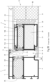
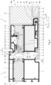
- the leaf profile of the door leaf 2 has an inner shell 11 and an outer shell 12, which are connected to each other via insulating webs 13A and 13B.
- the resulting cavity is filled with insulation 14.
- the inner shell 11 has a rebate 15 on its side facing the frame 1, which serves to accommodate an inner stop seal 16.
- the inner cover layer 19 is connected to the inner shell 11 of the sash profile by means of an adhesive layer 21.
- the outer cover layer 20 is also connected to the outer shell 12 of the sash profile by means of an adhesive layer 22.
- the adhesive layers 21, 22 can be designed as an adhesive layer or as double-sided adhesive tape.
- Fig. 1B also shows a fitting rebate 24 between the frame 1 and the sash profile.
- a sealing strip 25 can be seen, which is attached to the insulating bar 13A.
- a glazing rebate 26 is also shown on the side of the sash profile opposite the fitting rebate 24.
- a glazing rebate insulation 27, which is attached to the insulating bar 13B, provides further insulation between the sash profile and the door panel 17.
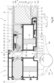
- a support surface 46 can be created on the inner shell 11 of the sash profile. Between the support surface 46 and the inner cover layer 19, a circumferential sealing strip 47 is arranged, which enables an additional connection of the inner cover layer 19 to the inner shell 11 of the sash profile at a height corresponding to the first holding profile 29.
- the door panel 17 of a door according to the invention also has, like the one in the Figures 1A and 1B
- the door shown has an insulating core 18.
- the insulating core 18 consists of an inner insulating core half 18A and an outer insulating core half 18B.
- the inner insulating core half 18A is connected to the inner cover layer 19 and the outer insulation core half 18B is attached to the outer cover layer 20.
- Both the inner insulation core half 18A and the outer insulation core half 18B are essentially cuboid-shaped.
- the outer insulation core half 18B is in two parts, with a first part 48 made of a deformation-compensating material, in particular a foam, and a second part 49 made of an insulating material, in particular a PU foam.
- a shoulder 50 is formed on the insulating core 18.
- the insulating core halves 18A, 18B are attached to one of their side surfaces on the inner and outer cover layers 19, 20, respectively.
- a parting plane 18C of the insulating core 18 lies between the outer and inner insulating core halves 18A, 18B.
- the area formed by the shoulder 50 can be reduced or enlarged by shifting the parting plane 18C toward the inner cover layer 19 or toward the outer cover layer 20. If the shoulder 50 is shifted toward the outer cover layer 20, the area provided for the holding element 45 becomes larger. If the parting plane 18C is shifted toward the inner cover layer 19, the area provided for the holding element 45 becomes smaller.
- the shoulder 50 should be designed such that the retaining element 45 can be arranged on the shoulder 50 and a gap is formed between the retaining element 45 and the insulating core 18.
- the insulating core halves 18A, 18B are dimensioned such that a gap G1 is formed between the end of the inner shell 11 of the sash profile facing away from the frame 1 and the outer insulating core half 18B, or between the end of the inner shell 11 of the sash profile facing away from the frame 1 and the inner insulating core half 18A.
- the gap G1 has a width of ⁇ 4 mm, in particular ⁇ 3 mm, and particularly preferably ⁇ 2 mm.
- the insulation core halves 18A, 18B are dimensioned such that a gap G2 is formed between the end of the outer insulation core half 18B facing the inner cover layer 19 and the retaining element 45.
- the gap G2 is designed to compensate for tolerances during assembly.
- the gap G2 should be as narrow as possible so that it has only a minimal impact on the thermal insulation.
- the Fig. 2A The designs shown apply to the entire circumferential leaf profile of door leaf 2.
- Fig. 2B is a horizontal section of the door from Fig. 2A in the area of a screw-on door hinge 51, via which the frame 1 and the door leaf 2 are connected to one another.
- the screw-on door hinge 51 has a hinge flap 51A assigned to the frame 1 and a hinge flap 51B assigned to the door leaf 2.
- the hinge flap 51B assigned to the door leaf 2 is fastened to the door leaf 2 via a fastening screw 52 running through the support surface 46.
- the sealing strip 47 which is designed according to a suitable thickness and width and is arranged between the inside of the inner cover layer 19 and the support surface 46, the risk of Deformation of the inner cover layer 19 is minimized when screwing the hinge flap 51B assigned to the door leaf 2.
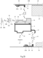
- Fig. 2c is a horizontal section of the door from Fig. 2A in the area of a handle 53.
- a strip for attaching the handle 53 is arranged.
- the strip is designed as an angle profile 54.
- the angle profile 54 is not circumferential, but only formed in sections in the area provided for attaching the handle 53. This has a beneficial effect on the material requirements.
- a recess in the insulating core 18 only needs to be provided in certain sections, which in turn has a positive effect on the insulating properties of the door.
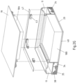
- FIG. 2E The corner area of the door leaf is shown in perspective, analogous to the representation in Fig. 2D While the retaining clips 33, 43 are individually inserted into the corresponding groove of the insulating webs 34 or into the receiving grooves 44 of the holding elements 45, all other holding means, such as the first holding profiles 29, the second holding profiles 39, the insulating webs 34, the receiving grooves 44 of the holding elements 45, the clip profiles 35, the sealing strips 38 and the sealing strips 47 are designed according to the length of the respective inner shells 11 of the sash profile, wherein the first holding profiles 29 and the second retaining profiles 39 are not mitred.
- Fig. 2F the corner area of the door leaf is made of Fig. 2E with a mounted inside in one of the Fig. 2E corresponding view and in Fig. 2G the corner area of the door leaf 2 Fig. 2E with a mounted exterior in one of the Fig. 2E corresponding view.
- Fig. 3 is a further embodiment of a door according to the invention in one of the Fig. 2A corresponding horizontal section.
- Fig. 3 The door shown has a flush interior and exterior, so that a system joint SF is visible on both the inside and the outside.
- Fig. 4 is a further embodiment of a door according to the invention in one of the Fig. 2A
- the door is shown in the corresponding horizontal section.
- Fig. 4 has a surface offset on the inside and outside.
- the frame 1 and the door leaf 2 are not aligned with each other on both the outside and the inside. This results in a surface offset on the outside, which is shown as reference symbol FV in the drawing.
- a rebate is formed on the inside of the door, which is shown as reference symbol AS in the drawing.
- Fig. 5 is a further embodiment of a door according to the invention in one of the Fig. 2A corresponding horizontal section.
- Fig. 5 The door shown has a flush outer side and an offset inner side.
Landscapes
- Engineering & Computer Science (AREA)
- Civil Engineering (AREA)
- Structural Engineering (AREA)
- Securing Of Glass Panes Or The Like (AREA)
Applications Claiming Priority (1)
| Application Number | Priority Date | Filing Date | Title |
|---|---|---|---|
| DE102022130995.9A DE102022130995A1 (de) | 2022-11-23 | 2022-11-23 | Tür, insbesondere Haustür, und Verfahren zur Herstellung eines Türflügels für eine solche Tür |
Publications (3)
| Publication Number | Publication Date |
|---|---|
| EP4375472A1 EP4375472A1 (de) | 2024-05-29 |
| EP4375472B1 true EP4375472B1 (de) | 2025-06-25 |
| EP4375472C0 EP4375472C0 (de) | 2025-06-25 |
Family
ID=88506529
Family Applications (1)
| Application Number | Title | Priority Date | Filing Date |
|---|---|---|---|
| EP23204993.2A Active EP4375472B1 (de) | 2022-11-23 | 2023-10-20 | Tür, insbesondere haustür, und verfahren zur herstellung eines türflügels für eine solche tür |
Country Status (3)
| Country | Link |
|---|---|
| EP (1) | EP4375472B1 (pl) |
| DE (1) | DE102022130995A1 (pl) |
| PL (1) | PL4375472T3 (pl) |
Family Cites Families (11)
| Publication number | Priority date | Publication date | Assignee | Title |
|---|---|---|---|---|
| DE8316155U1 (de) * | 1983-06-03 | 1983-11-24 | Gebrüder Uhl GmbH & Co KG, 7981 Vogt | Tuer, insbesondere verschwenkbar gehaltene tuer |
| DE202010013064U1 (de) * | 2010-12-06 | 2012-03-07 | Dr. Hahn Gmbh & Co. Kg | Anordnung zur Kabelführung |
| DE202011000669U1 (de) * | 2011-03-23 | 2012-06-26 | Zoran Sencar | Schichtaufbau für Türblatt |
| DE102012108929A1 (de) | 2011-10-12 | 2013-04-18 | Hörmann KG Eckelhausen | Haustür-Türblatt sowie Herstellverfahren hierfür |
| ITBZ20110056A1 (it) * | 2011-11-18 | 2013-05-19 | Finstral Spa Ag | Telai per serramenti in materiale termoplastico saldabile, rivestibili con materiali diversi |
| DE202013000307U1 (de) | 2013-01-12 | 2013-04-08 | OBUK Haustürfüllungen GmbH & Co. KG | Haustürflügel mit Klipsverbindung |
| DE202013102945U1 (de) | 2013-07-04 | 2014-10-06 | Heroal - Johann Henkenjohann Gmbh & Co. Kg | Tür mit einer flügelüberdeckenden Türfüllung |
| EP3269915B1 (de) | 2016-07-14 | 2019-08-28 | SCHÜCO International KG | Türflügel, tür und verfahren zur herstellung des türflügels |
| DE102018116218A1 (de) * | 2018-07-04 | 2020-01-09 | Mecklenburger Bauelemente Gmbh | Türflügel und Verfahren zur Montage eines Türflügels |
| FR3106846B1 (fr) * | 2020-01-31 | 2022-01-28 | Euradif | Ouvrant de porte equipe d’un cadre a epaisseur adaptable |
| DE102020131834A1 (de) | 2020-12-01 | 2022-06-02 | Heroal - Johann Henkenjohann Gmbh & Co. Kg | Tür, insbesondere Haustür und Verfahren zur Herstellung eines Türflügels für eine solche Tür |
-
2022
- 2022-11-23 DE DE102022130995.9A patent/DE102022130995A1/de active Pending
-
2023
- 2023-10-20 PL PL23204993.2T patent/PL4375472T3/pl unknown
- 2023-10-20 EP EP23204993.2A patent/EP4375472B1/de active Active
Also Published As
| Publication number | Publication date |
|---|---|
| EP4375472C0 (de) | 2025-06-25 |
| DE102022130995A1 (de) | 2024-05-23 |
| PL4375472T3 (pl) | 2025-09-08 |
| EP4375472A1 (de) | 2024-05-29 |
Similar Documents
| Publication | Publication Date | Title |
|---|---|---|
| DE19900793C2 (de) | Brandschutzleiste | |
| CH699766A2 (de) | Rahmenanschlussteil zur Befestigung an einem Rahmen. | |
| EP2824270A1 (de) | Flächenelement einer Brandschutzverglasung, insbesondere Glastür für Brandschutzzwecke zur Vermeidung des Durchtritts von Feuer und Rauch im Brandfall von einem Raum in einen anderen | |
| AT516308B1 (de) | Fensterelement | |
| DE4005953A1 (de) | Beschlag fuer fenster und tueren | |
| EP4375472B1 (de) | Tür, insbesondere haustür, und verfahren zur herstellung eines türflügels für eine solche tür | |
| DE102004038246B4 (de) | Vorrichtung zur Montage eines Fensterelementes o. dgl. Baugruppen | |
| DE102020131834A1 (de) | Tür, insbesondere Haustür und Verfahren zur Herstellung eines Türflügels für eine solche Tür | |
| EP0183985A1 (de) | Metallprofil für eine Türzarge und Türzarge hergestellt unter Verwendung eines derartigen Metallprofils | |
| EP3318709B1 (de) | Fensteranordnung, und verfahren zu deren montage | |
| EP4191011B1 (de) | Rahmenteil und daraus hergestellter membranrahmen | |
| EP3059373B1 (de) | Türblatt mit schlosstasche sowie verfahren zur herstellung | |
| EP0792992A1 (de) | Nachrüstzarge für Türen | |
| DE102011008765A1 (de) | Profilanordnung, Rahmen und Rahmenanordnung | |
| DE9308300U1 (de) | Eckzarge für Türen o.dgl. | |
| EP1811112B1 (de) | Scheibenverklebung | |
| DE202007006736U1 (de) | Aufnahmevorrichtung zur Aufnahme einer Bedeckungseinrichtung | |
| DE102017101003A1 (de) | Kombi-Glashalter und damit ausgerüstetes Holz-Alu-Verbundfenster | |
| DE202005000603U1 (de) | Anschlussprofil und Riegel-Pfosten-Konstruktion | |
| DE10115970B4 (de) | Zarge, insbesondere für eine Brandschutztür | |
| DE29618315U1 (de) | Fenster oder Türen mit Verglasung | |
| EP4411096A1 (de) | Fensterbankabschluss, anordnung und fenster mit einer fensterbank und einem solchen fensterbankabschluss | |
| AT411917B (de) | Verbindungsvorrichtung für zumindest eine halteleiste an einem bauelement sowie bauelement mit einer derartigen verbindungsvorrichtung | |
| DE102017108237A1 (de) | Fensteranordnung, und Verfahren zu deren Montage | |
| AT502155B1 (de) | Rahmenloses isolierglaselement sowie beschlag- oder befestigungssystem für das isolierglaselement |
Legal Events
| Date | Code | Title | Description |
|---|---|---|---|
| PUAI | Public reference made under article 153(3) epc to a published international application that has entered the european phase |
Free format text: ORIGINAL CODE: 0009012 |
|
| STAA | Information on the status of an ep patent application or granted ep patent |
Free format text: STATUS: THE APPLICATION HAS BEEN PUBLISHED |
|
| AK | Designated contracting states |
Kind code of ref document: A1 Designated state(s): AL AT BE BG CH CY CZ DE DK EE ES FI FR GB GR HR HU IE IS IT LI LT LU LV MC ME MK MT NL NO PL PT RO RS SE SI SK SM TR |
|
| P01 | Opt-out of the competence of the unified patent court (upc) registered |
Free format text: CASE NUMBER: APP_41324/2024 Effective date: 20240712 |
|
| STAA | Information on the status of an ep patent application or granted ep patent |
Free format text: STATUS: REQUEST FOR EXAMINATION WAS MADE |
|
| 17P | Request for examination filed |
Effective date: 20241024 |
|
| RBV | Designated contracting states (corrected) |
Designated state(s): AL AT BE BG CH CY CZ DE DK EE ES FI FR GB GR HR HU IE IS IT LI LT LU LV MC ME MK MT NL NO PL PT RO RS SE SI SK SM TR |
|
| GRAP | Despatch of communication of intention to grant a patent |
Free format text: ORIGINAL CODE: EPIDOSNIGR1 |
|
| STAA | Information on the status of an ep patent application or granted ep patent |
Free format text: STATUS: GRANT OF PATENT IS INTENDED |
|
| RIC1 | Information provided on ipc code assigned before grant |
Ipc: E06B 3/70 20060101ALN20250211BHEP Ipc: E06B 3/263 20060101ALN20250211BHEP Ipc: E06B 3/82 20060101AFI20250211BHEP |
|
| INTG | Intention to grant announced |
Effective date: 20250303 |
|
| GRAS | Grant fee paid |
Free format text: ORIGINAL CODE: EPIDOSNIGR3 |
|
| GRAA | (expected) grant |
Free format text: ORIGINAL CODE: 0009210 |
|
| STAA | Information on the status of an ep patent application or granted ep patent |
Free format text: STATUS: THE PATENT HAS BEEN GRANTED |
|
| AK | Designated contracting states |
Kind code of ref document: B1 Designated state(s): AL AT BE BG CH CY CZ DE DK EE ES FI FR GB GR HR HU IE IS IT LI LT LU LV MC ME MK MT NL NO PL PT RO RS SE SI SK SM TR |
|
| REG | Reference to a national code |
Ref country code: GB Ref legal event code: FG4D Free format text: NOT ENGLISH |
|
| REG | Reference to a national code |
Ref country code: CH Ref legal event code: EP |
|
| REG | Reference to a national code |
Ref country code: DE Ref legal event code: R096 Ref document number: 502023001227 Country of ref document: DE |
|
| REG | Reference to a national code |
Ref country code: CH Ref legal event code: EP |
|
| REG | Reference to a national code |
Ref country code: IE Ref legal event code: FG4D Free format text: LANGUAGE OF EP DOCUMENT: GERMAN |
|
| U01 | Request for unitary effect filed |
Effective date: 20250708 |
|
| U07 | Unitary effect registered |
Designated state(s): AT BE BG DE DK EE FI FR IT LT LU LV MT NL PT RO SE SI Effective date: 20250714 |
|
| PG25 | Lapsed in a contracting state [announced via postgrant information from national office to epo] |
Ref country code: NO Free format text: LAPSE BECAUSE OF FAILURE TO SUBMIT A TRANSLATION OF THE DESCRIPTION OR TO PAY THE FEE WITHIN THE PRESCRIBED TIME-LIMIT Effective date: 20250925 Ref country code: GR Free format text: LAPSE BECAUSE OF FAILURE TO SUBMIT A TRANSLATION OF THE DESCRIPTION OR TO PAY THE FEE WITHIN THE PRESCRIBED TIME-LIMIT Effective date: 20250926 |
|
| PG25 | Lapsed in a contracting state [announced via postgrant information from national office to epo] |
Ref country code: HR Free format text: LAPSE BECAUSE OF FAILURE TO SUBMIT A TRANSLATION OF THE DESCRIPTION OR TO PAY THE FEE WITHIN THE PRESCRIBED TIME-LIMIT Effective date: 20250625 |
|
| PG25 | Lapsed in a contracting state [announced via postgrant information from national office to epo] |
Ref country code: RS Free format text: LAPSE BECAUSE OF FAILURE TO SUBMIT A TRANSLATION OF THE DESCRIPTION OR TO PAY THE FEE WITHIN THE PRESCRIBED TIME-LIMIT Effective date: 20250925 |
|
| U20 | Renewal fee for the european patent with unitary effect paid |
Year of fee payment: 3 Effective date: 20251021 |
|
| PG25 | Lapsed in a contracting state [announced via postgrant information from national office to epo] |
Ref country code: IS Free format text: LAPSE BECAUSE OF FAILURE TO SUBMIT A TRANSLATION OF THE DESCRIPTION OR TO PAY THE FEE WITHIN THE PRESCRIBED TIME-LIMIT Effective date: 20251025 |
|
| PG25 | Lapsed in a contracting state [announced via postgrant information from national office to epo] |
Ref country code: SM Free format text: LAPSE BECAUSE OF FAILURE TO SUBMIT A TRANSLATION OF THE DESCRIPTION OR TO PAY THE FEE WITHIN THE PRESCRIBED TIME-LIMIT Effective date: 20250625 |
|
| PG25 | Lapsed in a contracting state [announced via postgrant information from national office to epo] |
Ref country code: CZ Free format text: LAPSE BECAUSE OF FAILURE TO SUBMIT A TRANSLATION OF THE DESCRIPTION OR TO PAY THE FEE WITHIN THE PRESCRIBED TIME-LIMIT Effective date: 20250625 |
|
| PGFP | Annual fee paid to national office [announced via postgrant information from national office to epo] |
Ref country code: PL Payment date: 20251013 Year of fee payment: 3 |
|
| PG25 | Lapsed in a contracting state [announced via postgrant information from national office to epo] |
Ref country code: SK Free format text: LAPSE BECAUSE OF FAILURE TO SUBMIT A TRANSLATION OF THE DESCRIPTION OR TO PAY THE FEE WITHIN THE PRESCRIBED TIME-LIMIT Effective date: 20250625 |
|
| PG25 | Lapsed in a contracting state [announced via postgrant information from national office to epo] |
Ref country code: ES Free format text: LAPSE BECAUSE OF FAILURE TO SUBMIT A TRANSLATION OF THE DESCRIPTION OR TO PAY THE FEE WITHIN THE PRESCRIBED TIME-LIMIT Effective date: 20250625 |