EP4375472B1 - Door, in particular house door, and method for manufacturing a door leaf for such a door - Google Patents
Door, in particular house door, and method for manufacturing a door leaf for such a door Download PDFInfo
- Publication number
- EP4375472B1 EP4375472B1 EP23204993.2A EP23204993A EP4375472B1 EP 4375472 B1 EP4375472 B1 EP 4375472B1 EP 23204993 A EP23204993 A EP 23204993A EP 4375472 B1 EP4375472 B1 EP 4375472B1
- Authority
- EP
- European Patent Office
- Prior art keywords
- door
- profile
- leaf
- cover layer
- retaining
- Prior art date
- Legal status (The legal status is an assumption and is not a legal conclusion. Google has not performed a legal analysis and makes no representation as to the accuracy of the status listed.)
- Active
Links
Images


Classifications
-
- E—FIXED CONSTRUCTIONS
- E06—DOORS, WINDOWS, SHUTTERS, OR ROLLER BLINDS IN GENERAL; LADDERS
- E06B—FIXED OR MOVABLE CLOSURES FOR OPENINGS IN BUILDINGS, VEHICLES, FENCES OR LIKE ENCLOSURES IN GENERAL, e.g. DOORS, WINDOWS, BLINDS, GATES
- E06B3/00—Window sashes, door leaves, or like elements for closing wall or like openings; Layout of fixed or moving closures, e.g. windows in wall or like openings; Features of rigidly-mounted outer frames relating to the mounting of wing frames
- E06B3/70—Door leaves
- E06B3/82—Flush doors, i.e. with completely flat surface
- E06B3/822—Flush doors, i.e. with completely flat surface with an internal foursided frame
-
- E—FIXED CONSTRUCTIONS
- E06—DOORS, WINDOWS, SHUTTERS, OR ROLLER BLINDS IN GENERAL; LADDERS
- E06B—FIXED OR MOVABLE CLOSURES FOR OPENINGS IN BUILDINGS, VEHICLES, FENCES OR LIKE ENCLOSURES IN GENERAL, e.g. DOORS, WINDOWS, BLINDS, GATES
- E06B3/00—Window sashes, door leaves, or like elements for closing wall or like openings; Layout of fixed or moving closures, e.g. windows in wall or like openings; Features of rigidly-mounted outer frames relating to the mounting of wing frames
- E06B3/04—Wing frames not characterised by the manner of movement
- E06B3/263—Frames with special provision for insulation
- E06B3/2632—Frames with special provision for insulation with arrangements reducing the heat transmission, other than an interruption in a metal section
- E06B2003/26332—Arrangements reducing the heat transfer in the glazing rabbet or the space between the wing and the casing frame
-
- E—FIXED CONSTRUCTIONS
- E06—DOORS, WINDOWS, SHUTTERS, OR ROLLER BLINDS IN GENERAL; LADDERS
- E06B—FIXED OR MOVABLE CLOSURES FOR OPENINGS IN BUILDINGS, VEHICLES, FENCES OR LIKE ENCLOSURES IN GENERAL, e.g. DOORS, WINDOWS, BLINDS, GATES
- E06B3/00—Window sashes, door leaves, or like elements for closing wall or like openings; Layout of fixed or moving closures, e.g. windows in wall or like openings; Features of rigidly-mounted outer frames relating to the mounting of wing frames
- E06B3/04—Wing frames not characterised by the manner of movement
- E06B3/263—Frames with special provision for insulation
- E06B2003/26349—Details of insulating strips
- E06B2003/26387—Performing extra functions
- E06B2003/26389—Holding sealing strips or forming sealing abutments
-
- E—FIXED CONSTRUCTIONS
- E06—DOORS, WINDOWS, SHUTTERS, OR ROLLER BLINDS IN GENERAL; LADDERS
- E06B—FIXED OR MOVABLE CLOSURES FOR OPENINGS IN BUILDINGS, VEHICLES, FENCES OR LIKE ENCLOSURES IN GENERAL, e.g. DOORS, WINDOWS, BLINDS, GATES
- E06B3/00—Window sashes, door leaves, or like elements for closing wall or like openings; Layout of fixed or moving closures, e.g. windows in wall or like openings; Features of rigidly-mounted outer frames relating to the mounting of wing frames
- E06B3/70—Door leaves
- E06B2003/7011—Door leaves with easily replaceable or interchangeable panels
-
- E—FIXED CONSTRUCTIONS
- E06—DOORS, WINDOWS, SHUTTERS, OR ROLLER BLINDS IN GENERAL; LADDERS
- E06B—FIXED OR MOVABLE CLOSURES FOR OPENINGS IN BUILDINGS, VEHICLES, FENCES OR LIKE ENCLOSURES IN GENERAL, e.g. DOORS, WINDOWS, BLINDS, GATES
- E06B3/00—Window sashes, door leaves, or like elements for closing wall or like openings; Layout of fixed or moving closures, e.g. windows in wall or like openings; Features of rigidly-mounted outer frames relating to the mounting of wing frames
- E06B3/70—Door leaves
- E06B3/7015—Door leaves characterised by the filling between two external panels
- E06B2003/7023—Door leaves characterised by the filling between two external panels of foam type
-
- E—FIXED CONSTRUCTIONS
- E06—DOORS, WINDOWS, SHUTTERS, OR ROLLER BLINDS IN GENERAL; LADDERS
- E06B—FIXED OR MOVABLE CLOSURES FOR OPENINGS IN BUILDINGS, VEHICLES, FENCES OR LIKE ENCLOSURES IN GENERAL, e.g. DOORS, WINDOWS, BLINDS, GATES
- E06B3/00—Window sashes, door leaves, or like elements for closing wall or like openings; Layout of fixed or moving closures, e.g. windows in wall or like openings; Features of rigidly-mounted outer frames relating to the mounting of wing frames
- E06B3/70—Door leaves
- E06B2003/7046—Door leaves with provisions for locks, hinges or other fittings
-
- E—FIXED CONSTRUCTIONS
- E06—DOORS, WINDOWS, SHUTTERS, OR ROLLER BLINDS IN GENERAL; LADDERS
- E06B—FIXED OR MOVABLE CLOSURES FOR OPENINGS IN BUILDINGS, VEHICLES, FENCES OR LIKE ENCLOSURES IN GENERAL, e.g. DOORS, WINDOWS, BLINDS, GATES
- E06B3/00—Window sashes, door leaves, or like elements for closing wall or like openings; Layout of fixed or moving closures, e.g. windows in wall or like openings; Features of rigidly-mounted outer frames relating to the mounting of wing frames
- E06B3/70—Door leaves
- E06B2003/7059—Specific frame characteristics
- E06B2003/7074—Metal frames
- E06B2003/7076—Metal frames insulated
-
- E—FIXED CONSTRUCTIONS
- E06—DOORS, WINDOWS, SHUTTERS, OR ROLLER BLINDS IN GENERAL; LADDERS
- E06B—FIXED OR MOVABLE CLOSURES FOR OPENINGS IN BUILDINGS, VEHICLES, FENCES OR LIKE ENCLOSURES IN GENERAL, e.g. DOORS, WINDOWS, BLINDS, GATES
- E06B3/00—Window sashes, door leaves, or like elements for closing wall or like openings; Layout of fixed or moving closures, e.g. windows in wall or like openings; Features of rigidly-mounted outer frames relating to the mounting of wing frames
- E06B3/70—Door leaves
- E06B2003/7059—Specific frame characteristics
- E06B2003/7092—Specific frame characteristics with frame members not directly or resiliently connected to each other
-
- E—FIXED CONSTRUCTIONS
- E06—DOORS, WINDOWS, SHUTTERS, OR ROLLER BLINDS IN GENERAL; LADDERS
- E06B—FIXED OR MOVABLE CLOSURES FOR OPENINGS IN BUILDINGS, VEHICLES, FENCES OR LIKE ENCLOSURES IN GENERAL, e.g. DOORS, WINDOWS, BLINDS, GATES
- E06B3/00—Window sashes, door leaves, or like elements for closing wall or like openings; Layout of fixed or moving closures, e.g. windows in wall or like openings; Features of rigidly-mounted outer frames relating to the mounting of wing frames
- E06B3/04—Wing frames not characterised by the manner of movement
- E06B3/263—Frames with special provision for insulation
- E06B3/26301—Frames with special provision for insulation with prefabricated insulating strips between two metal section members
- E06B3/26303—Frames with special provision for insulation with prefabricated insulating strips between two metal section members with thin strips, e.g. defining a hollow space between the metal section members
-
- E—FIXED CONSTRUCTIONS
- E06—DOORS, WINDOWS, SHUTTERS, OR ROLLER BLINDS IN GENERAL; LADDERS
- E06B—FIXED OR MOVABLE CLOSURES FOR OPENINGS IN BUILDINGS, VEHICLES, FENCES OR LIKE ENCLOSURES IN GENERAL, e.g. DOORS, WINDOWS, BLINDS, GATES
- E06B3/00—Window sashes, door leaves, or like elements for closing wall or like openings; Layout of fixed or moving closures, e.g. windows in wall or like openings; Features of rigidly-mounted outer frames relating to the mounting of wing frames
- E06B3/70—Door leaves
- E06B3/7001—Coverings therefor; Door leaves imitating traditional raised panel doors, e.g. engraved or embossed surfaces, with trim strips applied to the surfaces
Definitions
- the invention relates to a door, in particular a front door, with a surrounding frame as a support profile and at least one door leaf with a surrounding leaf profile, wherein the at least one door leaf has a door panel and wherein the door leaf has on its outer side an outer cover layer which is detachably fastened to the leaf profile and covers the leaf, wherein a first holding profile which is firmly connected to the outer cover layer serves to connect the leaf profile and the outer cover layer, wherein the first holding profile has at least one web, the end of which is provided with at least one widening or circumferential taper which can be locked to the leaf profile via at least one clamping element assigned to the outer cover layer, wherein the door leaf has on its inner side an inner cover layer which is detachably fastened to the leaf profile and covers the leaf, wherein a second holding profile which is firmly connected to the inner cover layer serves to connect the leaf profile and the inner cover layer, and wherein the second holding profile has at least one web, the end of which is provided with at least one widening or circum
- the present invention relates to the "leaf-covering" installation of the door panel, in which an outer and/or inner The covering layer of the door panel completely or partially covers the visible surface of the sash frame. This creates a seamless, flush appearance on both sides of the door.
- the current state of the art achieves the bond between a door panel that overlaps the leaf on both sides and the leaf profile by applying an adhesive or adhesive tape between the flush and overlapping surfaces. This bond can no longer be removed without damaging the door panel after the adhesive has cured/set.
- a door with a door panel covering the leaves on both sides is from the EP 2 581 542 B1 There, the inner and outer cover layers are attached to the sash profile using an adhesive.
- Front doors typically have a service life of between 25 and 50 years and often remain in the building until demolition. For this reason, there is a need for a flexible, adaptable front door in which the door panel, and especially the inner and outer covering layers, can be replaced as needed. This is not possible with a door panel that covers the entire leaf, where the covering layers are attached to the leaf profile with an adhesive.
- EP 3 269 915 B1 A reversible process is known in which the door panel is screwed to the inner shell of the door leaf profile in a form-fitting manner. This also eliminates the disadvantages of conventional adhesive technology.
- the positive fit between the leaf profile and the door panel prevents or at least minimizes relative movement between these two components. This negatively impacts the warping or deflection of the door leaf, caused by the bimetallic effect common in insulated aluminum doors due to a temperature difference between the inside and outside. The consequences are reduced ease of use due to stiffness of the door lock, even failure of the locking function, and increased drafts.
- DE 10 2020 131 834 A1 A door with a leaf-covering, outer cover layer is proposed, in which the outer cover layer is locked into a clamping element arranged on the leaf profile by means of a retaining profile, which is firmly connected to the outer cover layer.
- the outer cover layer is fixed in its locked position on the leaf profile by a positive locking of the retaining profile and an insulating bar attached to the leaf profile by means of a circumferential locking element.
- DE 10 2020 131 834 A1 The door disclosed has an insert filling on its inside, which is inserted like a glass element in the glass rebate of the door leaf.
- EP 2 754 836 B1 proposed to replace the usual adhesive bonding with a mechanical clip connection.
- the clip connection comprises a of the sash frame and a profile rail arranged on the inside of the door panel facing the sash frame, which can be clipped onto the mushroom-shaped clip body.
- EP 2 754 836 B1 The door shown here is designed with a recessed surface on both the inside and outside. This results in a limited watertightness on the outside, and therefore there is no need for sealing measures.
- EP 2 754 836 B1 The proposed connection between the front door panel and the leaf frame is not suitable for a flush-fitting door on the inside due to its large construction depth. In the case of a flush-fitting door, the DE 10 2020 131 834 A1 described problem arise.
- the invention is therefore based on the object of designing and developing the known door in such a way that an inner, leaf-covering covering layer can also be detachably attached to the leaf profile, without, however, having to accept the disadvantages mentioned above. Furthermore, a method is to be provided by which such a door can be manufactured.
- the sash profile has a holding element having a receiving groove at its end facing away from the frame and that the at least one clamping element assigned to the inner cover layer is arranged in the receiving groove.
- the position of the second retaining profile and the position of the attachment of the clamping element to the leaf profile are shifted so far into the area of the glass rebate of the door leaf compared to the attachment of the outer cover layer that the receiving groove for the clamping element, which takes up the greatest installation space towards the outside of the door, no longer protrudes into the area reserved for the corner connector or the door lock and the inner seal receptacle in the inner chamber of the leaf profile.
- a door according to the invention can be manufactured comparatively quickly, as there is no need to wait for the adhesive to harden. Furthermore, the use of identical components on the inside and outside of the door reduces assembly complexity and provides purchasing advantages. Furthermore, a door according to the invention enables reversible and thus non-destructive disassembly of both the inner and outer cover layers.
- the sash profile is formed integrally with the retaining element. In this case, no additional assembly step is required to attach the retaining element.
- the outer cover layer is fixed in its locked position on the door leaf by a positive locking mechanism from the first retaining profile using at least one circumferential locking element.
- the clamping elements associated with the outer cover layer are attached to an insulating bar arranged on the sash profile, for example, clamped in a groove provided for this purpose in the insulating bar.
- an insulating bar is arranged between the sash profile and the outer cover layer.
- a further teaching of the invention provides that the insulating bar is inserted into the sash profile on its side facing the outer covering layer.
- the The sash profile has at least two grooves on its side facing the outer cover layer and the insulating web has at least two corresponding webs.
- the at least one circumferential securing element is thus positively connected to both the first retaining profile and the insulating web.
- the securing elements can be manufactured in a wide variety of designs.
- the at least one securing element is designed as a clip-on profile, which is inserted from the outside into corresponding grooves in the first retaining profile and, if applicable, in the insulating strip.
- the at least one securing element is designed as a clip-on profile, which is inserted from the outside into corresponding grooves in the first retaining profile and, if applicable, in the insulating strip.
- four individual clip-on profiles are generally required, which, like the sash profiles and insulating strips, are mitered at their ends.
- the at least one securing element is designed as a securing profile, which is pivoted or pressed from the outside into a corresponding cavity in the first retaining profile and, if applicable, in the insulating bar.
- a securing profile which is pivoted or pressed from the outside into a corresponding cavity in the first retaining profile and, if applicable, in the insulating bar.
- several securing profiles are necessary to ensure the circumferential fixation of the first retaining profile and, if applicable, the insulating bar.
- the at least one clamping element assigned to the outer cover layer and/or the at least one clamping element assigned to the inner cover layer is a retaining clip designed as a spring element. It is particularly expedient to provide a sufficient number of retaining clips distributed over the entire length of the first and second retaining profiles to achieve the necessary frictional connection.
- the first retaining profile is glued to the outer cover layer and/or the second retaining profile is glued to the inner cover layer.
- Either a suitable adhesive or double-sided adhesive tape can be used for this purpose.
- the door panel comprises an outer insulating core half fastened to the outer cover layer and an inner insulating core half fastened to the inner cover layer, wherein the insulating core halves are substantially cuboid-shaped and wherein an end of the inner insulating core half associated with the sash profile protrudes by an offset dimension V from an end of the outer insulating core half associated with the sash profile, and wherein the offset dimension V corresponds to the extension of the holding element in the direction of the insulating core.
- a shoulder can be formed on a parting plane of the insulating core lying between the outer and inner insulating core halves.
- the shoulder can be made of different sizes by shifting the parting plane towards the outer cover layer or towards the inner cover layer.
- the shoulder should be designed such that the holding element can be arranged on the shoulder and a gap is formed between the holding element and the insulating core.
- a strip for attaching a handle or a grab bar is arranged at the end of the sash profile facing away from the frame. This makes it possible to attach a handle or a grab bar directly to the outer cover layer.
- the strip is particularly preferably designed as an angle profile.
- the strip is not circumferential, but only formed in sections in an area intended for the attachment of the handle or grab bar. This has a beneficial effect on the material requirements.
- a recess in the insulating core only needs to be provided in certain sections, which in turn has a positive effect on the insulating properties of the door.
- the door can be designed with a staggered surface on its exterior, eliminating the system joint typically found between the door leaf and the frame. This offers the advantage of better concealing non-optimal or non-uniform gaps between the door leaf and the frame caused by daily use. Furthermore, the absence of a system joint, which usually also includes the transition between the actual door leaf and the cover layer of the door panel, benefits both burglary protection and watertightness, as this transition is now protected behind the outer sealing layer of the frame.
- the door is designed flush on its inside with a system joint between the frame and the inner cover layer.
- the inner surface of the frame and the surface of the inner cover layer are flush with each other. A circumferential system joint is visible between these two elements.
- the door can be designed to open from the inside. This offers the same advantage as the exterior design: it can more effectively conceal non-optimal or uneven gaps between the door leaf and the frame caused by daily use.
- a sealing strip can be arranged on the securing element.
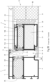
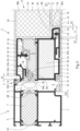
- the leaf profile of the door leaf 2 has an inner shell 11 and an outer shell 12, which are connected to each other via insulating webs 13A and 13B.
- the resulting cavity is filled with insulation 14.
- the inner shell 11 has a rebate 15 on its side facing the frame 1, which serves to accommodate an inner stop seal 16.
- the inner cover layer 19 is connected to the inner shell 11 of the sash profile by means of an adhesive layer 21.
- the outer cover layer 20 is also connected to the outer shell 12 of the sash profile by means of an adhesive layer 22.
- the adhesive layers 21, 22 can be designed as an adhesive layer or as double-sided adhesive tape.
- Fig. 1B also shows a fitting rebate 24 between the frame 1 and the sash profile.
- a sealing strip 25 can be seen, which is attached to the insulating bar 13A.
- a glazing rebate 26 is also shown on the side of the sash profile opposite the fitting rebate 24.
- a glazing rebate insulation 27, which is attached to the insulating bar 13B, provides further insulation between the sash profile and the door panel 17.
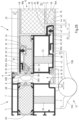
- a support surface 46 can be created on the inner shell 11 of the sash profile. Between the support surface 46 and the inner cover layer 19, a circumferential sealing strip 47 is arranged, which enables an additional connection of the inner cover layer 19 to the inner shell 11 of the sash profile at a height corresponding to the first holding profile 29.
- the door panel 17 of a door according to the invention also has, like the one in the Figures 1A and 1B
- the door shown has an insulating core 18.
- the insulating core 18 consists of an inner insulating core half 18A and an outer insulating core half 18B.
- the inner insulating core half 18A is connected to the inner cover layer 19 and the outer insulation core half 18B is attached to the outer cover layer 20.
- Both the inner insulation core half 18A and the outer insulation core half 18B are essentially cuboid-shaped.
- the outer insulation core half 18B is in two parts, with a first part 48 made of a deformation-compensating material, in particular a foam, and a second part 49 made of an insulating material, in particular a PU foam.
- a shoulder 50 is formed on the insulating core 18.
- the insulating core halves 18A, 18B are attached to one of their side surfaces on the inner and outer cover layers 19, 20, respectively.
- a parting plane 18C of the insulating core 18 lies between the outer and inner insulating core halves 18A, 18B.
- the area formed by the shoulder 50 can be reduced or enlarged by shifting the parting plane 18C toward the inner cover layer 19 or toward the outer cover layer 20. If the shoulder 50 is shifted toward the outer cover layer 20, the area provided for the holding element 45 becomes larger. If the parting plane 18C is shifted toward the inner cover layer 19, the area provided for the holding element 45 becomes smaller.
- the shoulder 50 should be designed such that the retaining element 45 can be arranged on the shoulder 50 and a gap is formed between the retaining element 45 and the insulating core 18.
- the insulating core halves 18A, 18B are dimensioned such that a gap G1 is formed between the end of the inner shell 11 of the sash profile facing away from the frame 1 and the outer insulating core half 18B, or between the end of the inner shell 11 of the sash profile facing away from the frame 1 and the inner insulating core half 18A.
- the gap G1 has a width of ⁇ 4 mm, in particular ⁇ 3 mm, and particularly preferably ⁇ 2 mm.
- the insulation core halves 18A, 18B are dimensioned such that a gap G2 is formed between the end of the outer insulation core half 18B facing the inner cover layer 19 and the retaining element 45.
- the gap G2 is designed to compensate for tolerances during assembly.
- the gap G2 should be as narrow as possible so that it has only a minimal impact on the thermal insulation.
- the Fig. 2A The designs shown apply to the entire circumferential leaf profile of door leaf 2.
- Fig. 2B is a horizontal section of the door from Fig. 2A in the area of a screw-on door hinge 51, via which the frame 1 and the door leaf 2 are connected to one another.
- the screw-on door hinge 51 has a hinge flap 51A assigned to the frame 1 and a hinge flap 51B assigned to the door leaf 2.
- the hinge flap 51B assigned to the door leaf 2 is fastened to the door leaf 2 via a fastening screw 52 running through the support surface 46.
- the sealing strip 47 which is designed according to a suitable thickness and width and is arranged between the inside of the inner cover layer 19 and the support surface 46, the risk of Deformation of the inner cover layer 19 is minimized when screwing the hinge flap 51B assigned to the door leaf 2.
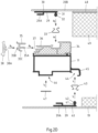
- Fig. 2c is a horizontal section of the door from Fig. 2A in the area of a handle 53.
- a strip for attaching the handle 53 is arranged.
- the strip is designed as an angle profile 54.
- the angle profile 54 is not circumferential, but only formed in sections in the area provided for attaching the handle 53. This has a beneficial effect on the material requirements.
- a recess in the insulating core 18 only needs to be provided in certain sections, which in turn has a positive effect on the insulating properties of the door.
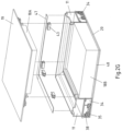
- FIG. 2E The corner area of the door leaf is shown in perspective, analogous to the representation in Fig. 2D While the retaining clips 33, 43 are individually inserted into the corresponding groove of the insulating webs 34 or into the receiving grooves 44 of the holding elements 45, all other holding means, such as the first holding profiles 29, the second holding profiles 39, the insulating webs 34, the receiving grooves 44 of the holding elements 45, the clip profiles 35, the sealing strips 38 and the sealing strips 47 are designed according to the length of the respective inner shells 11 of the sash profile, wherein the first holding profiles 29 and the second retaining profiles 39 are not mitred.
- Fig. 2F the corner area of the door leaf is made of Fig. 2E with a mounted inside in one of the Fig. 2E corresponding view and in Fig. 2G the corner area of the door leaf 2 Fig. 2E with a mounted exterior in one of the Fig. 2E corresponding view.
- Fig. 3 is a further embodiment of a door according to the invention in one of the Fig. 2A corresponding horizontal section.
- Fig. 3 The door shown has a flush interior and exterior, so that a system joint SF is visible on both the inside and the outside.
- Fig. 4 is a further embodiment of a door according to the invention in one of the Fig. 2A
- the door is shown in the corresponding horizontal section.
- Fig. 4 has a surface offset on the inside and outside.
- the frame 1 and the door leaf 2 are not aligned with each other on both the outside and the inside. This results in a surface offset on the outside, which is shown as reference symbol FV in the drawing.
- a rebate is formed on the inside of the door, which is shown as reference symbol AS in the drawing.
- Fig. 5 is a further embodiment of a door according to the invention in one of the Fig. 2A corresponding horizontal section.
- Fig. 5 The door shown has a flush outer side and an offset inner side.
Landscapes
- Engineering & Computer Science (AREA)
- Civil Engineering (AREA)
- Structural Engineering (AREA)
- Securing Of Glass Panes Or The Like (AREA)
Description
Die Erfindung betrifft eine Tür, insbesondere eine Haustür, mit einem umlaufenden Blendrahmen als Trägerprofil und wenigstens einem Türflügel mit einem umlaufenden Flügelprofil, wobei der wenigstens eine Türflügel eine Türfüllung aufweist und wobei der Türflügel auf seiner Außenseite eine lösbar auf dem Flügelprofil befestigte und flügelüberdeckende äußere Deckschicht aufweist, wobei zur Verbindung von Flügelprofil und äußerer Deckschicht ein erstes Halteprofil dient, welches fest mit der äußeren Deckschicht verbunden ist, wobei das erste Halteprofil wenigstens einen Steg aufweist, dessen Ende mit je wenigstens einer Verbreiterung oder umlaufenden Verjüngung versehen ist, welche über wenigstens ein der äußeren Deckschicht zugeordnetes Klemmelement mit dem Flügelprofil verrastbar ist, wobei der Türflügel auf seiner Innenseite eine lösbar auf dem Flügelprofil befestigte und flügelüberdeckende innere Deckschicht aufweist, wobei zur Verbindung von Flügelprofil und innerer Deckschicht ein zweites Halteprofil dient, welches fest mit der inneren Deckschicht verbunden ist und wobei das zweite Halteprofil wenigstens einen Steg aufweist, dessen Ende mit je wenigstens einer Verbreiterung oder umlaufenden Verjüngung versehen ist, welche über wenigstens ein der inneren Deckschicht zugeordnetes Klemmelement mit dem Flügelprofil verrastbar ist. Des Weiteren betrifft die Erfindung ein Verfahren zum Herstellen eines Türflügels für eine solche Tür.The invention relates to a door, in particular a front door, with a surrounding frame as a support profile and at least one door leaf with a surrounding leaf profile, wherein the at least one door leaf has a door panel and wherein the door leaf has on its outer side an outer cover layer which is detachably fastened to the leaf profile and covers the leaf, wherein a first holding profile which is firmly connected to the outer cover layer serves to connect the leaf profile and the outer cover layer, wherein the first holding profile has at least one web, the end of which is provided with at least one widening or circumferential taper which can be locked to the leaf profile via at least one clamping element assigned to the outer cover layer, wherein the door leaf has on its inner side an inner cover layer which is detachably fastened to the leaf profile and covers the leaf, wherein a second holding profile which is firmly connected to the inner cover layer serves to connect the leaf profile and the inner cover layer, and wherein the second holding profile has at least one web, the end of which is provided with at least one widening or circumferential taper which can be locked to the leaf profile via at least one of the A clamping element associated with the inner cover layer can be locked to the leaf profile. Furthermore, the invention relates to a method for producing a door leaf for such a door.
Bedingt durch den Wunsch nach gestalterischer Freiheit, aus Gewichtsgründen und aufgrund der Anforderungen hinsichtlich Wärmeschutz und Einbruchschutz werden Türen heute sehr häufig mit einer Türfüllung ausgestattet. Im Gegensatz zu den herkömmlichen Einsatzfüllungen, die wie ein Glaselement im Glasfalz eines Türflügels eingesetzt werden, betrifft die vorliegende Erfindung die als "flügelüberdeckend" bezeichnete Montage der Türfüllung, bei der eine äußere und/oder eine innere Deckschicht der Türfüllung die Ansichtsfläche des Flügelrahmens ganz oder teilweise verdeckt. Hierdurch wird eine fugenlose, flächenbündige Optik auf beiden Seiten der Tür erreicht.Due to the desire for design freedom, weight reasons, and requirements regarding thermal insulation and burglary protection, doors today are very often equipped with a door panel. In contrast to conventional insert panels, which are inserted like a glass element in the glass rebate of a door leaf, the present invention relates to the "leaf-covering" installation of the door panel, in which an outer and/or inner The covering layer of the door panel completely or partially covers the visible surface of the sash frame. This creates a seamless, flush appearance on both sides of the door.
Die Herstellung des Verbundes einer beidseitig flügelüberdeckender Türfüllung und dem Flügelprofil wird nach derzeitigem Stand der Technik dahingehend erreicht, dass zwischen den sich plan zueinander liegenden und überdeckenden Flächen ein Klebstoff oder Klebeband aufgebracht wird. Dieser Verbund ist nach dem Aushärten/Abbinden der Klebstoffe nicht mehr zerstörungsfrei zu lösen.The current state of the art achieves the bond between a door panel that overlaps the leaf on both sides and the leaf profile by applying an adhesive or adhesive tape between the flush and overlapping surfaces. This bond can no longer be removed without damaging the door panel after the adhesive has cured/set.
Eine Tür mit einer beidseitig flügelüberdeckenden Türfüllung ist aus der
Haustüren haben häufig eine Einsatzzeit zwischen 25 bis 50 Jahren und verbleiben oft sogar bis zum Abriss im Gebäude. Aus diesem Grund besteht ein Bedarf an einer flexiblen, anpassungsfähigen Haustür, bei der eine Türfüllung und insbesondere eine innere und eine äußere Deckschicht bei Bedarf ausgetauscht werden kann. Dies ist bei einer flügelüberdeckenden Türfüllung, bei der die Deckschichten mittels einem Klebstoff an dem Flügelprofil befestigt sind, nicht möglich.Front doors typically have a service life of between 25 and 50 years and often remain in the building until demolition. For this reason, there is a need for a flexible, adaptable front door in which the door panel, and especially the inner and outer covering layers, can be replaced as needed. This is not possible with a door panel that covers the entire leaf, where the covering layers are attached to the leaf profile with an adhesive.
Eine in der
Des Weiteren ist aus der
Der zuvor genannte Stand der Technik, bei dem auf eine Verklebung der Deckschichten verzichtet werden kann, offenbart in der Praxis gewisse Nachteile. Die sowohl in der
Außerdem wird in allen Fällen durch den hergestellten Formschluss zwischen Flügelprofil und Türfüllung eine Relativbewegung dieser beider Komponenten untereinander verhindert oder zumindest auf ein Minimum reduziert. Dies wirkt sich negativ auf den Verzug bzw. die Durchbiegung des Türflügels aus, hervorgerufen durch den bei isolierten Aluminium-Türen bekannten Bimetall-Effekt aufgrund eines Temperaturunterschieds zwischen Innen- und Außenseite. Die Folge sind ein reduzierter Bedienkomfort durch Schwergängigkeit des Türschlosses bis hin zum Versagen der Schließfunktion sowie erhöhte Zuglufterscheinungen.Furthermore, in all cases, the positive fit between the leaf profile and the door panel prevents or at least minimizes relative movement between these two components. This negatively impacts the warping or deflection of the door leaf, caused by the bimetallic effect common in insulated aluminum doors due to a temperature difference between the inside and outside. The consequences are reduced ease of use due to stiffness of the door lock, even failure of the locking function, and increased drafts.
Zusätzlich kommt als Nachteil des in der
Um einen verminderten Montageaufwand und eine optimierte Verzugshemmung zu realisieren, wird in der
Die in der
Um auf eine Verklebung einer beidseitig flügelüberdeckenden Haustürfüllung mit dem Flügelrahmen verzichten zu können, wird in der
Bei Anwendung der in der
Des Weiteren würden bei Anwendung der in der
Der Erfindung liegt daher die Aufgabe zugrunde, die bekannte Tür so auszugestalten und weiterzubilden, dass auch eine innere, flügelüberdeckende Deckschicht lösbar an dem Flügelprofil befestigt werden kann, ohne jedoch die im Voranstehenden genannten Nachteile in Kauf nehmen zu müssen. Zudem soll ein Verfahren angegeben werden, mit dem sich eine entsprechende Tür herstellen lässt.The invention is therefore based on the object of designing and developing the known door in such a way that an inner, leaf-covering covering layer can also be detachably attached to the leaf profile, without, however, having to accept the disadvantages mentioned above. Furthermore, a method is to be provided by which such a door can be manufactured.
Diese Aufgabe wird zunächst für eine Tür mit dem Oberbegriff von Anspruch 1 dadurch gelöst, dass das Flügelprofil an seinem dem Blendrahmen abgewandten Ende ein eine Aufnahmenut aufweisendes Halteelement aufweist und dass das wenigstens eine der inneren Deckschicht zugeordnete Klemmelement in der Aufnahmenut angeordnet ist.This object is initially achieved for a door with the preamble of
Die Position des zweiten Halteprofils und die Position der Anbringung des Klemmelements an das Flügelprofil sind im Vergleich zu der Anbringung der äußeren Deckschicht so weit in den Bereich der Glasfalz des Türflügels verschoben, dass die Aufnahmenut für das Klemmelement, welches die größte Bauraum-Ausdehnung in Richtung der Außenseite der Tür beansprucht, nicht mehr in den für den Eckverbinder bzw. das Türschloss und die innere Dichtungsaufnahme reservierten Bereich in der Innenkammer des Flügelprofils hineinragt.The position of the second retaining profile and the position of the attachment of the clamping element to the leaf profile are shifted so far into the area of the glass rebate of the door leaf compared to the attachment of the outer cover layer that the receiving groove for the clamping element, which takes up the greatest installation space towards the outside of the door, no longer protrudes into the area reserved for the corner connector or the door lock and the inner seal receptacle in the inner chamber of the leaf profile.
Damit einher geht eine deutliche Reduktion des Montageaufwands, da das gleiche Verbundverfahren sowohl für die Innenseite als auch für die Außenseite der Tür verwendet werden kann. Zudem lässt sich eine erfindungsgemäße Tür vergleichsweise schnell fertigen, da ein etwaiges Warten auf die Kleberaushärtung wegfällt. Des Weiteren können mit der Verwendung gleicher Komponenten an der Innen- und Außenseite der Tür eine Komplexitätsreduzierung in der Montage und Einkaufsvorteile realisiert werden. Darüber hinaus ermöglicht eine erfindungsgemäße Tür eine reversible und somit zerstörungsfreie Demontage sowohl der inneren als auch der äußeren Deckschicht.This is accompanied by a significant reduction in assembly effort, as the same bonding process is used for both the inside and outside of the door can be used. Furthermore, a door according to the invention can be manufactured comparatively quickly, as there is no need to wait for the adhesive to harden. Furthermore, the use of identical components on the inside and outside of the door reduces assembly complexity and provides purchasing advantages. Furthermore, a door according to the invention enables reversible and thus non-destructive disassembly of both the inner and outer cover layers.
Vorteilhafterweise ist das Flügelprofil mit dem Halteelement einstückig ausgebildet. In diesem Fall ist kein zusätzlicher Montageschritt zur Anbringung des Halteelements notwendig.Advantageously, the sash profile is formed integrally with the retaining element. In this case, no additional assembly step is required to attach the retaining element.
Nach einer bevorzugten Ausgestaltung der Erfindung ist die äußere Deckschicht in ihrer verrasteten Position auf dem Türflügel durch eine formschlüssige Sicherung von dem ersten Halteprofil mittels wenigstens einem umlaufenden Sicherungselement fixiert. Damit einher geht eine deutliche Reduktion des Montageaufwandes der äußeren Deckschicht, da auf die vielen für die einzelnen Verbindungselemente notwendigen Bohrungen verzichtet werden kann. Durch ausreichend seitliches Spiel in der Aufnahme der Sicherungselemente gegenüber dem Halteprofil, welches auf der Innenseite der äußeren Deckschicht der Türfüllung befestigt ist, wird eine schwimmende Lagerung der Türfüllung ermöglicht. Dadurch werden die verzugshemmenden Eigenschaften des Türflügels positiv unterstützt.According to a preferred embodiment of the invention, the outer cover layer is fixed in its locked position on the door leaf by a positive locking mechanism from the first retaining profile using at least one circumferential locking element. This results in a significant reduction in the assembly effort for the outer cover layer, as the numerous holes required for the individual connecting elements can be omitted. Sufficient lateral play in the retaining element holder relative to the retaining profile, which is attached to the inside of the outer cover layer of the door panel, enables a floating mounting of the door panel. This positively supports the warp-resistant properties of the door leaf.
In weiterer bevorzugter Ausgestaltung der Erfindung sind dabei die der äußeren Deckschicht zugeordneten Klemmelemente an einem am Flügelprofil angeordneten Isoliersteg befestigt, beispielsweise in einer dafür vorgesehenen Nut des Isoliersteges verklemmt. In diesem Fall ist zwischen dem Flügelprofil und der äußeren Deckschicht ein Isoliersteg angeordnet.In a further preferred embodiment of the invention, the clamping elements associated with the outer cover layer are attached to an insulating bar arranged on the sash profile, for example, clamped in a groove provided for this purpose in the insulating bar. In this case, an insulating bar is arranged between the sash profile and the outer cover layer.
Eine weitere Lehre der Erfindung sieht vor, dass der Isoliersteg in das Flügelprofil an seiner der äußeren Deckschicht zugewandten Seite eingeschoben ist. Dazu weist das Flügelprofil an seiner der äußeren Deckschicht zugewandten Seite wenigstens zwei Nuten und der Isoliersteg wenigstens zwei korrespondierende Stege auf.A further teaching of the invention provides that the insulating bar is inserted into the sash profile on its side facing the outer covering layer. For this purpose, the The sash profile has at least two grooves on its side facing the outer cover layer and the insulating web has at least two corresponding webs.
Nach einer weiteren bevorzugten Ausbildung der Erfindung greifen das wenigstens eine umlaufende Sicherungselement und der Isoliersteg sowie das wenigstens eine umlaufende Sicherungselement und das erste Halteprofil ineinander. Das wenigstens eine umlaufende Sicherungselement ist also sowohl mit dem ersten Halteprofil als auch mit dem Isoliersteg formschlüssig verbunden.According to a further preferred embodiment of the invention, the at least one circumferential securing element and the insulating web, as well as the at least one circumferential securing element and the first retaining profile, engage with each other. The at least one circumferential securing element is thus positively connected to both the first retaining profile and the insulating web.
Die Sicherungselemente können in verschiedensten Ausführungen hergestellt werden.The securing elements can be manufactured in a wide variety of designs.
Nach einer bevorzugten Ausführung der Erfindung ist das wenigstens eine Sicherungselement als Klipsprofil ausgebildet, welches von außen in korrespondierenden Nuten im ersten Halteprofil und gegebenenfalls im Isoliersteg eingeschoben wird. Für eine umlaufende Sicherung sind in der Regel also vier einzelne Klipsprofile notwendig, welche, genau wie die Flügelprofile und Isolierstege an ihren Enden auf Gehrung geschnitten sind.According to a preferred embodiment of the invention, the at least one securing element is designed as a clip-on profile, which is inserted from the outside into corresponding grooves in the first retaining profile and, if applicable, in the insulating strip. For a circumferential securing arrangement, four individual clip-on profiles are generally required, which, like the sash profiles and insulating strips, are mitered at their ends.
Eine alternativ bevorzugte Ausgestaltung sieht vor, dass das wenigstens eine Sicherungselement als Sicherungsprofil ausgebildet ist, welches von außen in einen korrespondierenden Hohlraum im ersten Halteprofil und gegebenenfalls im Isoliersteg hineingeschwenkt oder hineingepresst wird. Auch hier sind wieder mehrere Sicherungsprofile notwendig, um die umlaufende Fixierung vom ersten Halteprofil und gegebenenfalls Isoliersteg zu gewährleisten.An alternative preferred embodiment provides that the at least one securing element is designed as a securing profile, which is pivoted or pressed from the outside into a corresponding cavity in the first retaining profile and, if applicable, in the insulating bar. Here, too, several securing profiles are necessary to ensure the circumferential fixation of the first retaining profile and, if applicable, the insulating bar.
Eine weitere bevorzugte Ausgestaltung sieht vor, dass das wenigstens eine Sicherungselement als Sicherungsclip ausgeführt ist, welcher schwenkbar am Isoliersteg angeordnet ist. Der Sicherungsclip ist dabei auch als (umlaufende) Leiste ausgebildet, welche gemäß einer weiteren bevorzugten Lehre auch einstückig mit dem Isoliersteg ausgebildet sein kann. Bei einer solchen Ausführung ist die Sicherungsclipleiste beispielsweise über ein Filmscharnier mit dem Isoliersteg verbunden.A further preferred embodiment provides that the at least one securing element is designed as a securing clip, which is pivotably arranged on the insulating bar. The securing clip is also designed as a (circumferential) strip, which according to a further preferred teaching can also be formed integrally with the insulating bar. In such an embodiment, the The safety clip strip is connected to the insulating bar, for example, via a film hinge.
In weiterer bevorzugter Ausgestaltung der Erfindung ist das wenigstens eine der äußeren Deckschicht zugeordnete Klemmelement und/oder das wenigstens eine der inneren Deckschicht zugeordnete Klemmelement eine als Federelement ausgebildete Halteklammer. Dabei ist es besonders zweckmäßig, dass zum Erreichen des notwendigen Kraftschlusses eine ausreichende Anzahl von über die gesamte Länge der ersten und zweiten Halteprofile verteilt angeordneten Halteklammern vorgesehen ist.In a further preferred embodiment of the invention, the at least one clamping element assigned to the outer cover layer and/or the at least one clamping element assigned to the inner cover layer is a retaining clip designed as a spring element. It is particularly expedient to provide a sufficient number of retaining clips distributed over the entire length of the first and second retaining profiles to achieve the necessary frictional connection.
Besonders bevorzugt ist das erste Halteprofil auf die äußere Deckschicht und/oder das zweite Halteprofil auf die innere Deckschicht aufgeklebt. Dazu kann entweder ein geeigneter Klebstoff oder ein doppelseitiges Klebeband verwendet werden.Particularly preferably, the first retaining profile is glued to the outer cover layer and/or the second retaining profile is glued to the inner cover layer. Either a suitable adhesive or double-sided adhesive tape can be used for this purpose.
Nach einer bevorzugten Lehre der Erfindung ist vorgesehen, dass das erste und/oder das zweite Halteprofil als im äußeren Bereich der äußeren bzw. der inneren Deckschicht umlaufendes Halteprofil ausgeführt ist. Auf diese Weise erfolgt die Verbindung von Flügelprofil und äußerer bzw. innerer Deckschicht sehr gleichmäßig im rahmenartigen äußeren Bereich des Türflügels.According to a preferred teaching of the invention, the first and/or second retaining profile is designed as a retaining profile that runs around the outer region of the outer or inner cover layer. In this way, the connection between the leaf profile and the outer or inner cover layer is achieved very evenly in the frame-like outer region of the door leaf.
In weiterer bevorzugter Ausgestaltung der Erfindung weist das Flügelprofil an seinem zur inneren Deckschicht gerichteten Ende eine Auflagefläche auf, wobei besonders bevorzugt zwischen der Auflagefläche und der inneren Deckschicht ein Dichtband angeordnet ist, welches insbesondere umlaufend ausgebildet ist. Das Dichtband kann toleranzbedingte Unterschiede ausgleichen, dichtet ab und kann durch seine dämpfende Eigenschaft ein Klappern der inneren Deckschicht verhindern. Bei entsprechender Ausgestaltung der Erfindung können der Blendrahmen und der Türflügel besonders gut über wenigstens ein Aufschraub-Türband, insbesondere wenigstens zwei Aufschraub-Türbänder, miteinander verbunden werden. Das wenigstens eine Aufschraub-Türband weist einen dem Blendrahmen zugeordneten und einem dem Türflügel zugeordneten Bandlappen auf, wobei der dem Türflügel zugeordnete Bandlappen bevorzugt über ein durch die Auflagefläche des Flügelprofils verlaufendes Befestigungsmittel, insbesondere über eine durch die Auflagefläche des Flügelprofils verlaufende Befestigungsschraube, an dem Türflügel befestigt wird.In a further preferred embodiment of the invention, the sash profile has a support surface at its end facing the inner cover layer, wherein a sealing strip is particularly preferably arranged between the support surface and the inner cover layer, which sealing strip is in particular designed to be circumferential. The sealing strip can compensate for tolerance-related differences, seals and, due to its damping properties, can prevent the inner cover layer from rattling. With a corresponding embodiment of the invention, the frame and the door leaf can be particularly well connected to one another via at least one screw-on door hinge, in particular at least two screw-on door hinges. The at least one screw-on door hinge has a and a hinge flap assigned to the door leaf, wherein the hinge flap assigned to the door leaf is preferably fastened to the door leaf via a fastening means running through the support surface of the leaf profile, in particular via a fastening screw running through the support surface of the leaf profile.
Durch die Anordnung des Halteelements an dem dem Blendrahmen abgewandten Ende des Flügelprofils kann eine plane Auflagefläche an der Position der Verschraubung der Aufschraub-Türbänder generiert werden. Unter Zuhilfenahme eines entsprechend einer passenden Dicke und Breite ausgelegten Dichtbandes wird das Risiko einer Deformierung der inneren Deckschicht bei Verschraubung des Bandlappens minimiert. Das bevorzugt umlaufend eingesetzte Dichtband sorgt aufgrund seiner notwendigen Haftung für eine zusätzliche Positionierung der inneren Deckschicht an dem Flügelprofil gegenüberliegend zu der Position, an der auch die äußere Deckschicht über das erste Halteprofil an dem Flügelprofil befestigt ist.By arranging the retaining element at the end of the sash profile facing away from the frame, a flat support surface can be created at the screw connection position of the screw-on door hinges. Using a sealing strip of the appropriate thickness and width minimizes the risk of deformation of the inner cover layer when screwing the hinge flap. Due to its necessary adhesion, the sealing strip, which is preferably used all the way around, ensures additional positioning of the inner cover layer on the sash profile opposite the position where the outer cover layer is attached to the sash profile via the first retaining profile.
Nach einer bevorzugten Lehre der Erfindung ist vorgesehen, dass die Türfüllung eine an der äußeren Deckschicht befestigte äußere Dämmkernhälfte und eine an der inneren Deckschicht befestigte innere Dämmkernhälfte aufweist, wobei die Dämmkernhälften im Wesentlichen quaderförmig ausgebildet sind und wobei ein dem Flügelprofil zugeordnetes Ende der inneren Dämmkernhälfte um ein Versatzmaß V von einem dem Flügelprofil zugeordneten Ende der äußeren Dämmkernhälfte zurücksteht und wobei das Versatzmaß V der Erstreckung des Halteelements in Richtung des Dämmkerns entspricht. Auf diese Weise kann ein Absatz an einer zwischen der äußeren und der inneren Dämmkernhälfte liegenden Trennebene des Dämmkerns ausgebildet werden. Der Absatz kann durch Verschiebung der Trennebene in Richtung der äußeren Deckschicht oder in Richtung der inneren Deckschicht unterschiedlich groß ausgebildet werden. Der Absatz sollte so gestaltet sein, dass das Halteelement an dem Absatz angeordnet werden kann und zwischen dem Halteelement und dem Dämmkern ein Zwischenraum gebildet wird.According to a preferred teaching of the invention, the door panel comprises an outer insulating core half fastened to the outer cover layer and an inner insulating core half fastened to the inner cover layer, wherein the insulating core halves are substantially cuboid-shaped and wherein an end of the inner insulating core half associated with the sash profile protrudes by an offset dimension V from an end of the outer insulating core half associated with the sash profile, and wherein the offset dimension V corresponds to the extension of the holding element in the direction of the insulating core. In this way, a shoulder can be formed on a parting plane of the insulating core lying between the outer and inner insulating core halves. The shoulder can be made of different sizes by shifting the parting plane towards the outer cover layer or towards the inner cover layer. The shoulder should be designed such that the holding element can be arranged on the shoulder and a gap is formed between the holding element and the insulating core.
Vorteilhafterweise sollten die Dämmkernhälften so an die Größe des Halteelements angepasst werden, dass ein Spalt G1 zwischen dem dem Blendrahmen abgewandten Ende des Flügelprofils und der äußeren Dämmkernhälfte bzw. zwischen dem dem Blendrahmen abgewandten Ende des Flügelprofils und der inneren Dämmkernhälfte ausgebildet ist, wobei der Spalt G1 eine Breite von ≤ 4 mm, insbesondere von ≤ 3 mm und besonders bevorzugt von ≤ 2 mm aufweist. Bei entsprechender Dimensionierung der Dämmkernhälften kann eine gute Wärmedämmung auch ohne eine zusätzliche Glasfalzdämmung erzielt werden.Advantageously, the insulation core halves should be adapted to the size of the retaining element such that a gap G1 is formed between the end of the sash profile facing away from the frame and the outer insulation core half, or between the end of the sash profile facing away from the frame and the inner insulation core half, wherein the gap G1 has a width of ≤ 4 mm, in particular ≤ 3 mm, and particularly preferably ≤ 2 mm. With appropriate dimensioning of the insulation core halves, good thermal insulation can be achieved even without additional glazing rebate insulation.
Besonders bevorzugt sind die Dämmkernhälften so dimensioniert, dass ein Spalt G2 zwischen dem zur inneren Deckschicht gerichteten Ende der äußeren Dämmkernhälfte und dem Halteelement ausgebildet ist, wobei der Spalt G2 für einen Toleranzausgleich bei der Montage ausgelegt ist. Der Spalt G2 sollte dabei so schmal wie möglich ausgebildet werden, so dass sich dieser nur minimal auf die Wärmedämmung auswirkt.Particularly preferably, the insulation core halves are dimensioned such that a gap G2 is formed between the end of the outer insulation core half facing the inner cover layer and the retaining element, wherein the gap G2 is designed to compensate for tolerances during assembly. The gap G2 should be as narrow as possible so that it has only a minimal impact on the thermal insulation.
Alternativ zur voranstehend erläuterten Ausbildung, könnte eine Aussparung in der inneren Dämmkernhälfte im Bereich des Halteelements vorgesehen werden. Dies würde allerdings zu einem zusätzlichen Bearbeitungsschritt in der Produktion führen und ist deshalb zu vermeiden.As an alternative to the design described above, a recess could be provided in the inner half of the insulation core in the area of the retaining element. However, this would result in an additional processing step in production and should therefore be avoided.
Um eine bessere Verzugshemmung zu gewährleisten, ist es zweckmäßig, die äußere Dämmkernhälfte zweiteilig auszubilden, wobei ein erster Teil aus einem verformungskompensierenden Material wie beispielsweise einem Schaumstoff und ein zweiter Teil aus einem dämmenden Material wie beispielsweise einem PU-Schaum gebildet ist. Dabei ist es besonders vorteilhaft, wenn der erste Teil aus dem verformungskompensierenden Material an der Innenseite der äußeren Deckschicht angeordnet ist und als verzugshemmende Zwischenschicht fungiert. Dies hat den Vorteil, dass die Längenausdehnung der äußeren Deckschicht nicht durch eine Verklebung mit einem relativ festen Körper, wie beispielsweise einem aus einem PU-Schaum gebildeten Körper, behindert wird, so dass die äußere Deckschicht auch bei einer Längenausdehnung annähernd gerade bleibt.To ensure better warpage resistance, it is advisable to construct the outer insulation core half in two parts, with a first part made of a deformation-compensating material such as a foam and a second part made of an insulating material such as a PU foam. It is particularly advantageous if the first part made of the deformation-compensating material is arranged on the inside of the outer cover layer and functions as a warpage-inhibiting intermediate layer. This has the advantage that the linear expansion of the outer cover layer is not limited by bonding to a relatively rigid body, such as a PU foam. formed body, so that the outer covering layer remains almost straight even when it expands in length.
Bei einer bevorzugten Ausführung der Erfindung ist eine Leiste zur Befestigung einer Handhabe oder einer Griffstange an dem dem Blendrahmen abgewandten Ende des Flügelprofils angeordnet. So ist es möglich, eine Handhabe oder eine Griffstange direkt auf der äußeren Deckschicht zu befestigen. Die Leiste ist besonders bevorzugt als Winkelprofil ausgebildet. Bei einer besonders vorteilhaften Ausgestaltung ist die Leiste nicht umlaufend, sondern nur abschnittsweise in einem für die Befestigung der Handhabe oder der Griffstange vorgesehenen Bereich ausgebildet. Dies wirkt sich vorteilhaft auf den Materialbedarf aus. Darüber hinaus muss bei einer entsprechenden Ausgestaltung der Leiste nur abschnittsweise eine Aussparung im Dämmkern vorgesehen werden, was sich wiederum positiv auf die Dämmeigenschaften der Tür auswirkt.In a preferred embodiment of the invention, a strip for attaching a handle or a grab bar is arranged at the end of the sash profile facing away from the frame. This makes it possible to attach a handle or a grab bar directly to the outer cover layer. The strip is particularly preferably designed as an angle profile. In a particularly advantageous embodiment, the strip is not circumferential, but only formed in sections in an area intended for the attachment of the handle or grab bar. This has a beneficial effect on the material requirements. Furthermore, with a corresponding design of the strip, a recess in the insulating core only needs to be provided in certain sections, which in turn has a positive effect on the insulating properties of the door.
Bei einer vorteilhaften Ausgestaltung der Erfindung ist die Tür an ihrer Außenseite flächenbündig mit einer Systemfuge zwischen dem Blendrahmen und der äußeren Deckschicht ausgebildet. In diesem Fall sind die äußere Oberfläche des Blendrahmens und die Oberfläche der äußeren Deckschicht miteinander fluchtend ausgeführt. Zwischen diesen beiden Elementen ist eine umlaufende Systemfuge erkennbar.In an advantageous embodiment of the invention, the door is designed to be flush on its exterior surface with a system joint between the frame and the outer covering layer. In this case, the outer surface of the frame and the surface of the outer covering layer are flush with each other. A circumferential system joint is visible between these two elements.
Alternativ kann die Tür an ihrer Außenseite flächenversetzt ausgebildet sein, so dass sich keine für eine solche Tür sonst typische Systemfuge zwischen Türflügel und Blendrahmen bildet. Dies bietet den Vorteil, nicht optimale bzw. einheitliche Spaltmaße zwischen Türflügel und Blendrahmen, hervorgerufen durch den täglichen Gebrauch, optisch besser kaschieren zu können. Außerdem ist das Fehlen der Systemfuge, in dessen Bereich auch meistens der Übergang zwischen eigentlichem Türflügel und Deckschicht der Türfüllung liegt, sowohl dem Einbruchschutz als auch der Schlagregendichtheit zuträglich, da sich dieser Übergang nunmehr geschützt hinter der äußeren Dichtebene des Blendrahmens wiederfindet.Alternatively, the door can be designed with a staggered surface on its exterior, eliminating the system joint typically found between the door leaf and the frame. This offers the advantage of better concealing non-optimal or non-uniform gaps between the door leaf and the frame caused by daily use. Furthermore, the absence of a system joint, which usually also includes the transition between the actual door leaf and the cover layer of the door panel, benefits both burglary protection and watertightness, as this transition is now protected behind the outer sealing layer of the frame.
Besonders bevorzugt ist die Tür an ihrer Innenseite flächenbündig mit einer Systemfuge zwischen dem Blendrahmen und der inneren Deckschicht ausbildet. In diesem Fall sind die innere Oberfläche des Blendrahmens und die Oberfläche der inneren Deckschicht miteinander fluchtend ausgeführt. Zwischen diesen beiden Elementen ist eine umlaufende Systemfuge erkennbar.Particularly preferably, the door is designed flush on its inside with a system joint between the frame and the inner cover layer. In this case, the inner surface of the frame and the surface of the inner cover layer are flush with each other. A circumferential system joint is visible between these two elements.
Alternativ zur voranstehend erläuterten Ausbildung kann die Tür innen aufschlagend ausbildet sein. Dies bietet hier den ebenso wie im Zusammenhang mit der Außenseite genannten Vorteil, nicht optimale bzw. einheitliche Spaltmaße zwischen Türflügel und Blendrahmen, hervorgerufen durch den täglichen Gebrauch, optisch besser kaschieren zu können.As an alternative to the design described above, the door can be designed to open from the inside. This offers the same advantage as the exterior design: it can more effectively conceal non-optimal or uneven gaps between the door leaf and the frame caused by daily use.
Schließlich wird die Aufgabe auch durch ein Verfahren zur Herstellung eines Türflügels für eine zuvor beschriebene Tür durch die folgenden Schritte gelöst:
- Einsetzen der der äußeren und der inneren Deckschicht zugeordneten Klemmelemente,
- Aufkleben des Dichtbands auf die Auflagefläche des Flügelprofils,
- Verrasten des ersten und des zweiten Halteprofils mit den jeweiligen Klemmelementen und
- Einschieben des Sicherungselementes zum Fixieren der äußeren Deckschicht in ihrer verrasteten Position.
- Inserting the clamping elements assigned to the outer and inner cover layers,
- Gluing the sealing tape onto the support surface of the sash profile,
- Locking the first and second holding profiles with the respective clamping elements and
- Insert the locking element to fix the outer cover layer in its locked position.
Optional kann eine Dichtleiste auf dem Sicherungselement angeordnet werden.Optionally, a sealing strip can be arranged on the securing element.
Die Erfindung wird nachfolgend anhand einer lediglich bevorzugte Ausführungsbeispiele darstellenden Zeichnung näher beschrieben. In der Zeichnung zeigen:
- Fig. 1A
- eine aus dem Stand der Technik bekannte Tür mit einem umlaufenden Blendrahmen und einem Türflügel in Seitenansicht,
- Fig. 1B
- einen Horizontalschnitt durch den Blendrahmen und den Türflügel entlang der Linie IB-IB aus
Fig. 1A , - Fig. 2A
- eine erfindungsgemäße Tür mit einer flächenversetzten Außenseite und einer flächenbündigen Innenseite in einer der
Fig. 1B entsprechenden Ansicht, - Fig. 2B
- einen Horizontalschnitt der Tür aus
Fig. 2A im Bereich eines Aufschraub-Türbands, - Fig. 2C
- einen Horizontalschnitt der Tür aus
Fig. 2A im Bereich einer Handhabe, - Fig. 2D
- die Montageschritte der geklipsten Verbindung des Türflügels aus
Fig. 2A mit den dazu notwendigen Einzelteilen, wieder im Horizontalschnitt, - Fig. 2E
- einen Eckbereich des Türflügels aus
Fig. 2D in perspektivischer Explosionszeichnung, - Fig. 2F
- der Eckbereich des Türflügels aus
Fig. 2E mit einer montierten Innenseite in einer derFig. 2E entsprechenden Ansicht, - Fig. 2G
- der Eckbereich des Türflügels aus
Fig. 2E mit einer montierten Außenseite in einer derFig. 2E entsprechenden Ansicht, - Fig. 3
- ein weiteres Ausführungsbeispiel einer erfindungsgemäßen Tür mit einer flächenbündigen Innen- und Außenseite in einem der
Fig. 2A entsprechenden Horizontalschnitt, - Fig. 4
- ein weiteres Ausführungsbeispiel einer erfindungsgemäßen Tür mit einer flächenversetzten Innen- und Außenseite in einem der
Fig. 2A entsprechenden Horizontalschnitt und - Fig. 5
- ein weiteres Ausführungsbeispiel einer erfindungsgemäßen Tür mit einer flächenbündigen Außenseite und einer flächenversetzten Innenseite in einem der
Fig. 2A entsprechenden Horizontalschnitt.
- Fig. 1A
- a door known from the prior art with a surrounding frame and a door leaf in side view,
- Fig. 1B
- a horizontal section through the frame and the door leaf along the line IB-IB
Fig. 1A , - Fig. 2A
- a door according to the invention with a surface-offset outer side and a flush inner side in one of the
Fig. 1B corresponding view, - Fig. 2B
- a horizontal section of the door
Fig. 2A in the area of a screw-on door hinge, - Fig. 2C
- a horizontal section of the door
Fig. 2A in the area of a handle, - Fig. 2D
- the assembly steps of the clipped connection of the door leaf
Fig. 2A with the necessary individual parts, again in horizontal section, - Fig. 2E
- a corner area of the door leaf
Fig. 2D in perspective exploded view, - Fig. 2F
- the corner area of the door leaf
Fig. 2E with a mounted inside in one of theFig. 2E corresponding view, - Fig. 2G
- the corner area of the door leaf
Fig. 2E with a mounted exterior in one of theFig. 2E corresponding view, - Fig. 3
- another embodiment of a door according to the invention with a flush inner and outer side in one of the
Fig. 2A corresponding horizontal section, - Fig. 4
- a further embodiment of a door according to the invention with a surface-offset inside and outside in one of the
Fig. 2A corresponding horizontal section and - Fig. 5
- a further embodiment of a door according to the invention with a flush outer side and a surface-offset inner side in one of the
Fig. 2A corresponding horizontal section.
In
Der Aufbau der Profile dieser bekannten Tür ist in
Man erkennt zunächst, dass der Blendrahmen 1 und der Türflügel 2 an der Außenseite nicht miteinander fluchten, so dass dies zu einem Flächenversatz führt, welcher als Bezugszeichen FV in der Zeichnung dargestellt ist. An der Innenseite sind der Blendrahmen 1 und der Türflügel 2 flächenbündig ausgeführt, so dass eine Systemfuge zwischen dem Blendrahmen 1 und dem Türflügel 2 gebildet wird, welche als Bezugszeichen SF in der Zeichnung dargestellt ist. Das Profil des Blendrahmens 1 besteht dabei aus einer Innenschale 4 und einer Außenschale 5, welche über Isolierstege 6A und 6B miteinander verbunden sind. In dem dazwischen befindlichen Hohlraum ist eine Dämmung 7 zur thermischen Isolation und Schallisolierung angebracht. An seiner offenen (in der Zeichnung: rechten) Seite weist die Dämmebene eine Dichtleiste 8 auf, welche mit dem Isoliersteg 6B verrastet ist. Die Außenschale 5 weist an ihrem in
Das Flügelprofil des Türflügels 2 weist eine Innenschale 11 und eine Außenschale 12 auf, welche über Isolierstege 13A und 13B miteinander verbunden sind. Auch hier ist der entstandene Hohlraum von einer Dämmung 14 ausgefüllt. Die Innenschale 11 weist auf ihrer zum Blendrahmen 1 gerichteten Seite einen Falz 15 auf, der zur Aufnahme einer inneren Anschlagdichtung 16 dient.The leaf profile of the
Die in
Die innere Deckschicht 19 ist mittels einer Klebeschicht 21 mit der Innenschale 11 des Flügelprofils verbunden. Die äußere Deckschicht 20 ist ebenfalls mittels einer Klebeschicht 22 mit der Außenschale 12 des Flügelprofils verbunden. Die Klebeschichten 21, 22 können dabei als Klebstoffschicht oder auch als doppelseitiges Klebeband ausgeführt sein. Zum Schutz des äußeren Endes der äußeren Deckschicht 20 dient eine Schutzleiste 23, welche in eine nicht näher bezeichnete Nut der Außenschale 12 eingeführt ist und dazu dient, Beschädigungen des empfindlichen Endes der äußeren Deckschicht 20 zu vermeiden.The
In die Innenschale 11 des Flügelprofils ist ein Eckverbinder 28 eingeschoben, über den die Innenschalen 11 der Flügelprofile umlaufend miteinander verbunden sind.A
Man erkennt deutlich, dass anstatt einer Außenschale bei der erfindungsgemäßen Ausführung von innen auf die äußere Deckschicht 20 ein erstes Halteprofil 29 mittels wiederum einer Klebeschicht 30 aufgeklebt ist. Das erste Halteprofil 29 weist an seinem zum Blendrahmen 1 weisenden Ende eine parallel zur äußeren Deckschicht 20 verlaufende Nut 29A auf. Am anderen Ende des ersten Halteprofils 29 erkennt man einen Steg 31, welcher an seinem Ende eine Verbreiterung 32 aufweist. Aus
Zur Fixierung der äußeren Deckschicht 20 in ihrer mit dem Isoliersteg 34 verrrasteten Position wird ein Sicherungselement verwendet, welches im Ausführungsbeispiel gemäß
Die innere Deckschicht 19 ist bei einer erfindungsgemäßen Tür über ein zweites Halteprofil 39 an der Innenschale 11 des Flügelprofils befestigt, wobei das zweite Halteprofil 39 mittels einer Klebeschicht 40 auf der Innenseite der inneren Deckschicht 19 aufgeklebt ist. Das zweite Halteprofil 39 ist in diesem Ausführungsbeispiel baugleich mit dem ersten Halteprofil 29 und verfügt ebenfalls über an seinem zum Blendrahmen 1 weisenden Ende eine parallel zur inneren Deckschicht 19 verlaufende Nut 39A, wobei die Nut 39A bei dem zweiten Halteprofil 39 keine Funktion erfüllt. Am anderen Ende des zweiten Halteprofils 39 erkennt man einen Steg 41, welcher an seinem Ende eine Verbreiterung 42 aufweist. Aus
Man erkennt in
Die Türfüllung 17 einer erfindungsgemäßen Tür weist ebenfalls wie die in den
An dem Dämmkern 18 ist ein Absatz 50 ausgebildet. Die Dämmkernhälften 18A, 18B sind an einer ihrer Seitenflächen an der inneren bzw. der äußeren Deckschicht 19, 20 befestigt. Zwischen der äußeren und der inneren Dämmkernhälfte 18A, 18B liegt eine Trennebene 18C des Dämmkerns 18. Indem ein dem Flügelprofil zugeordnetes Ende der inneren Dämmkernhälfte 18A um ein Versatzmaß V von einem dem Flügelprofil zugeordneten Ende der äußeren Dämmkernhälfte 18B zurücksteht wird der Absatz 50 an der Trennebene 18C des Dämmkerns 18 gebildet. Das Versatzmaß V entspricht der Erstreckung des Halteelements 45 in Richtung des Dämmkerns 18, so dass das Halteelement 45 an dem Absatz 50 angeordnet werden kann.A
Der durch den Absatz 50 gebildete Bereich kann durch Verschiebung der Trennebene 18C in Richtung der inneren Deckschicht 19 oder in Richtung der äußeren Deckschicht 20 verkleinert oder vergrößert werden. Wird der Absatz 50 in Richtung der äußeren Deckschicht 20 verschoben, wird der für das Halteelement 45 vorgesehene Bereich größer. Erfolgt eine Verschiebung der Trennebene 18C in Richtung der inneren Deckschicht 19, fällt der für das Halteelement 45 vorgesehene Bereich kleiner aus.The area formed by the
Der Absatz 50 sollte so gestaltet sein, dass das Halteelement 45 an dem Absatz 50 angeordnet werden kann und zwischen dem Halteelement 45 und dem Dämmkern 18 ein Spalt gebildet wird. Die Dämmkernhälften 18A, 18B sind so dimensioniert, dass ein Spalt G1 zwischen dem dem Blendrahmen 1 abgewandten Ende der Innenschale 11 des Flügelprofils und der äußeren Dämmkernhälfte 18B bzw. zwischen dem dem Blendrahmen 1 abgewandten Ende der Innenschale 11 des Flügelprofils und der inneren Dämmkernhälfte 18A ausgebildet ist. Der Spalt G1 weist eine Breite von ≤ 4 mm, insbesondere von ≤ 3 mm und besonders bevorzugt von ≤ 2 mm auf. Darüber hinaus sind die Dämmkernhälften 18A, 18B so dimensioniert, dass ein Spalt G2 zwischen dem zur inneren Deckschicht 19 gerichteten Ende der äußeren Dämmkernhälfte 18B und dem Halteelement 45 ausgebildet ist, wobei der Spalt G2 für einen Toleranzausgleich bei der Montage ausgelegt ist. Der Spalt G2 sollte dabei so schmal wie möglich ausgebildet werden, so dass sich dieser nur minimal auf die Wärmedämmung auswirkt.The
Bei entsprechender Dimensionierung der Dämmkernhälften 18A, 18B kann eine gute Wärmedämmung auch ohne eine zusätzliche Glasfalzdämmung erzielt werden.With appropriate dimensioning of the insulation core halves 18A, 18B, good thermal insulation can be achieved even without additional glazing rebate insulation.
Die in der
In
In
In
- Schritt a1:
Die Halteklammern 33 werden in eine korrespondierende nicht näher bezeichnete Nut des Isolierstegs 34 eingesetzt. - Schritt a2:
Das erste Halteprofils 29 wird mit dem Flügelprofil durch Erzeugung einer kraftschlüssigen und formschlüssigen Verbindung nach dem Einschieben des Stegs 31 verrastet, wobeidas verbreiterte Ende 32 ins Innere der Halteklammer 33 gepresst wird. - Schritt a3: Hierbei wird zur Fixierung der äußeren Deckschicht 20 in ihrer
mit dem Isoliersteg 34 verrrasteten Position ein Sicherungselement verwendet, welches im Ausführungsbeispiel gemäßFig. 2A bzw.Fig. 2B als Klipsprofil 35 ausgeführt ist,das den Klipsprofilsteg 35A,den Klemmsteg 35B undden Klipsprofilsteg 35C aufweist, wobei der obere Schenkel desKlipsprofils 35 indie Nut 29A des ersten Halteprofils 29,der Klipsprofilsteg 35A indie korrespondierende Nut 36 desIsolierstegs 34 und derKlipsprofilsteg 35C indie entsprechende Nut 37 desIsolierstegs 34 seitlich eingeschoben wird. - Schritt a4:
Auf den Klemmsteg 35B desKlipsprofils 35 wird dieDichtleiste 38 aufgepresst, welche dazu über dieKlemmnut 38A verfügt. - Schritt i1:
Die Halteklammern 43 werden indie Aufnahmenut 44 des Halteelements 45 eingesetzt. - Schritt i2:
Das umlaufende Dichtband 47 wird auf dieAuflagefläche 46der Innenschale 11 des Flügelprofils aufgeklebt. - Schritt i3:
Das zweite Halteprofils 39 wirdmit der Innenschale 11 des Flügelprofils durch Erzeugung einer kraftschlüssigen und formschlüssigen Verbindung nach dem Einschieben des Stegs 41 verrastet, wobeidas verbreiterte Ende 42 ins Innere der Halteklammer 43 gepresst wird.
- Step a1: The retaining clips 33 are inserted into a corresponding groove (not further designated) of the insulating
bar 34. - Step a2: The
first retaining profile 29 is locked to the sash profile by creating a force-locking and form-locking connection after inserting theweb 31, whereby thewidened end 32 is pressed into the interior of the retainingclip 33. - Step a3: In this case, a securing element is used to fix the
outer cover layer 20 in its locked position with the insulatingweb 34, which in the embodiment according toFig. 2A orFig. 2B designed as aclip profile 35, which theclip profile web 35A, the clampingweb 35B and theclip profile web 35C, wherein the upper leg of theclip profile 35 is inserted laterally into thegroove 29A of the first holdingprofile 29, theclip profile web 35A into the correspondinggroove 36 of the insulatingweb 34 and theclip profile web 35C into the correspondinggroove 37 of the insulatingweb 34. - Step a4: The sealing
strip 38 is pressed onto the clampingweb 35B of theclip profile 35, which has the clampinggroove 38A for this purpose. - Step i1: The retaining clips 43 are inserted into the receiving
groove 44 of the retainingelement 45. - Step i2: The
circumferential sealing strip 47 is glued to thesupport surface 46 of theinner shell 11 of the sash profile. - Step i3: The
second retaining profile 39 is locked to theinner shell 11 of the sash profile by creating a force-locking and form-locking connection after inserting theweb 41, whereby thewidened end 42 is pressed into the interior of the retainingclip 43.
Bei Montage des Türflügels 2 ist es unerheblich, ob zuerst die Außenseite (Schritte a1 bis a4) oder erst die Innenseite (Schritte i1 bis i3) montiert wird.When assembling
Zum besseren Verständnis ist in
In
In
In
- 11
- Blendrahmenframe
- 22
- Türflügeldoor leaf
- 33
- Türschwelledoor threshold
- 44
-
Innenschale des Blendrahmens 1Inner shell of the
frame 1 - 55
-
Außenschale des Blendrahmens 1Outer shell of the
frame 1 - 6A, 6B6A, 6B
- IsolierstegInsulating bar
- 77
- Dämmunginsulation
- 88
- Dichtleistesealing strip
- 99
- Anschlagstegstop bar
- 1010
- äußere Anschlagdichtungouter stop seal
- 1111
- Innenschale des FlügelprofilsInner shell of the wing profile
- 1212
- Außenschale des FlügelprofilsOuter shell of the wing profile
- 13A, 13B13A, 13B
- IsolierstegInsulating bar
- 1414
- Dämmunginsulation
- 1515
- Falzfold
- 1616
- innere Anschlagdichtunginner stop seal
- 1717
- TürfüllungDoor panel
- 1818
- DämmkernInsulating core
- 18A18A
-
innere Dämmkernhälfte des Dämmkerns 18inner insulation core half of the
insulation core 18 - 18B18B
-
äußere Dämmkernhälfte des Dämmkerns 18outer insulation core half of the
insulation core 18 - 18C18C
-
Trennebene des Dämmkerns 18Separation plane of the
insulation core 18 - 1919
- innere Deckschichtinner cover layer
- 2020
- äußere Deckschichtouter cover layer
- 2121
- Klebeschichtadhesive layer
- 2222
- Klebeschichtadhesive layer
- 2323
- Schutzleisteprotective strip
- 2424
- BeschlagfalzFitting rebate
- 2525
- Dichtleistesealing strip
- 2626
- GlasfalzGlass rebate
- 2727
- GlasfalzdämmungGlass rebate insulation
- 2828
- EckverbinderCorner connectors
- 2929
- erstes Halteprofilfirst holding profile
- 29A29A
-
Nut des ersten Halteprofils 29Groove of the
first retaining profile 29 - 3030
- Klebeschichtadhesive layer
- 3131
-
Steg des ersten Halteprofils 29Web of the
first retaining profile 29 - 3232
-
Verbreiterung des Stegs 31Widening of the
bridge 31 - 3333
-
der äußeren Deckschicht 20 zugeordnete Halteklammerretaining clip assigned to the
outer cover layer 20 - 3434
- IsolierstegInsulating bar
- 3535
- KlipsprofilClip profile
- 35A, 35C35A, 35C
- KlipsprofilstegClip profile bar
- 35B35B
- Klemmstegclamping bar
- 36, 3736, 37
-
Nut des Isolierstegs 34Groove of the insulating
bar 34 - 3838
- Dichtleistesealing strip
- 38A38A
- Klemmnutclamping groove
- 3939
- zweites Halteprofilsecond retaining profile
- 39A39A
-
Nut des zweiten Halteprofils 39Groove of the
second retaining profile 39 - 4040
- Klebeschichtadhesive layer
- 4141
-
Steg des zweiten Halteprofils 39Web of the
second retaining profile 39 - 4242
-
Verbreiterung des Stegs 41Widening of the
bridge 41 - 4343
-
der inneren Deckschicht 19 zugeordnete Halteklammerretaining clip assigned to the
inner cover layer 19 - 4444
- AufnahmenutReceiving groove
- 4545
- HalteelementHolding element
- 4646
- AuflageflächeSupport surface
- 4747
- Dichtbandsealing tape
- 4848
-
erster Teil der äußeren Dämmkernhälfte 18B des Dämmkerns 18first part of the outer
insulation core half 18B of theinsulation core 18 - 4949
-
zweiter Teil der äußeren Dämmkernhälfte 18B des Dämmkerns 18second part of the outer
insulation core half 18B of theinsulation core 18 - 5050
- AbsatzParagraph
- 5151
- Aufschraub-TürbandScrew-on door hinge
- 51A51A
-
dem Blendrahmen 1 zugeordneter Bandlappenhinge flap assigned to the
frame 1 - 51B51B
-
dem Türflügel 2 zugeordneter Bandlappenhinge flap assigned to
door leaf 2 - 5252
- BefestigungsschraubeFixing screw
- 5353
- HandhabeHandle
- 5454
- WinkelprofilAngle profile
- ASAS
- Aufschlagsurcharge
- FVFV
- FlächenversatzSurface offset
- G1, G2G1, G2
- Spaltgap
- VV
- VersatzmaßOffset dimension
Claims (18)
- Door, in particular front door, having a circumferential frame (1) as a carrier profile and at least one door leaf (2) with a circumferential leaf profile, wherein the at least one door leaf (2) has a door panel (17) and wherein the door leaf (2) has on its outer side an outer cover layer (20) which is detachably fastened to the leaf profile and covers the leaf, wherein a first retaining profile (29), which is firmly connected to the outer cover layer (20), serves to connect the leaf profile and the outer cover layer (20), and wherein the first retaining profile (29) has at least one web (31), the end of which is provided with at least one widening (32) or circumferential taper in each case, which can be latched to the leaf profile via at least one clamping element associated with the outer cover layer (20), the door leaf (2) having on its inner side an inner cover layer (19) which is detachably fastened to the leaf profile and covers the leaf, a second retaining profile (39), which is firmly connected to the inner cover layer (19), serves to connect the leaf profile and the inner cover layer (19), and wherein the second retaining profile (39) has at least one web (41), the end of each of which is provided with at least one widening (42) or circumferential taper, which can be latched to the leaf profile via at least one clamping element associated with the inner cover layer (19),
characterized in that
the leaf profile has a retaining element (45) with a retaining groove (44) at its end facing away from the frame (1) and that the at least one clamping element associated with the inner cover layer (19) is arranged in the retaining groove (44). - Door according to claim 1,
characterized in that
the outer cover layer (20) is fixed in its latched position on the door leaf (2) by a positive-locking securing of the first retaining profile (29) by means of at least one circumferential securing element. - Door according to claim 1 or 2,
characterized in that
the first retaining profile (29) is bonded to the outer cover layer (20) and/or the second retaining profile (39) is bonded to the inner cover layer (19). - Door according to claim 3,
characterized in that
a suitable adhesive (30, 40) or an adhesive tape is used to adhere the first and/or the second retaining profile (29, 39). - Door according to any one of claims 1 to 4,
characterized in that
the leaf profile has a bearing surface (46) at its end directed towards the inner cover layer (19). - Door according to claim 5,
characterized in that
a sealing strip (47) is arranged between the bearing surface (46) and the inner cover layer (19), which sealing strip is designed in particular to be circumferential. - Door according to claim 5 or 6,
characterized in that
the frame (1) and the door leaf (2) are connected to one another via at least one screw-on door hinge (51), in particular at least two screw-on door hinges (51), wherein the at least one screw-on door hinge (51) has a hinge flap (51A) associated with the frame (1) and a hinge flap (51B) associated with the door leaf (2), wherein the hinge tab (51B) associated with the door leaf (2) is fastened to the door leaf (2) via a fastening means extending through the bearing surface (46) of the leaf profile, in particular via a fastening screw (52) extending through the bearing surface (46) of the leaf profile. - Door according to any one of claims 1 to 7,
characterized in that
the door panel (17) has an outer insulating core half (18B) fastened to the outer cover layer (20) and an inner insulating core half (18A) fastened to the inner cover layer (19), the insulating core halves (18A, 18B) being substantially cuboid in shape, wherein an end of the inner insulating core half (18A) associated with the leaf profile projects back by an offset dimension (V) from an end of the outer insulating core half (18B) associated with the leaf profile, and wherein the offset dimension (V) corresponds to the extension of the retaining element (45) in the direction of the insulating core (18). - Door according to claim 8,
characterized in that
a gap G1 is formed between the end of the leaf profile facing away from the frame (1) and the outer insulating core half (18B) or between the end of the leaf profile facing away from the frame (1) and the inner insulating core half (18A), wherein the gap G1 has a width of ≤ 4 mm, in particular of ≤ 3 mm and particularly preferably of ≤ 2 mm. - Door according to claim 8 or 9,
characterized in that
a gap G2 is formed between the end of the outer insulating core half (18B) directed towards the inner cover layer (19) and the retaining element (45), the gap G2 being designed for tolerance compensation during assembly. - Door according to any one of claims 8 to 10,
characterized in that
the outer insulating core half (18B) is formed in two parts, a first part (48) being formed from a deformation-compensating material, in particular from a foam, and a second part (49) being formed from an insulating material, in particular from a PU foam, the first part (48) being arranged in particular on the inside of the outer cover layer (20). - Door according to any one of claims 1 to 11,
characterized in that
a strip for fastening a handle (53) or a handle bar is arranged at the end of the leaf profile facing away from the frame (1), the strip being designed in particular as an angled profile (54) and particularly preferably in sections in an area provided for fastening the handle (53) or the handle bar. - Door according to any one of claims 1 to 12,
characterized in that
the door is formed on its outer side flush with a system joint (SF) between the frame (1) and the outer cover layer (20). - Door according to any one of claims 1 to 12,
characterized in that
the door has an offset surface on its outer side. - Door according to any one of claims 1 to 14,
characterized in that
the door is formed flush on its inner side with a system joint (SF) between the frame (1) and the inner cover layer (19). - Door according to any one of claims 1 to 14,
characterized in that
the door is designed to open inwards. - A method of manufacturing a door leaf for a door according to any one of claims 1 to 16,
characterized with the following steps:- Inserting the clamping elements assigned to the outer (20) and inner cover layer (19),- Glue the sealing tape (47) to the bearing surface (46) of the leaf profile,- Locking of the first and second retaining profiles (29, 39) with the respective clamping elements and- Sliding in the securing element to fix the outer cover layer (20) in its latched position. - Method according to claim 17,
characterized in that
a sealing strip (8) is arranged on the securing element.
Applications Claiming Priority (1)
| Application Number | Priority Date | Filing Date | Title |
|---|---|---|---|
| DE102022130995.9A DE102022130995A1 (en) | 2022-11-23 | 2022-11-23 | Door, in particular front door, and method for producing a door leaf for such a door |
Publications (3)
| Publication Number | Publication Date |
|---|---|
| EP4375472A1 EP4375472A1 (en) | 2024-05-29 |
| EP4375472B1 true EP4375472B1 (en) | 2025-06-25 |
| EP4375472C0 EP4375472C0 (en) | 2025-06-25 |
Family
ID=88506529
Family Applications (1)
| Application Number | Title | Priority Date | Filing Date |
|---|---|---|---|
| EP23204993.2A Active EP4375472B1 (en) | 2022-11-23 | 2023-10-20 | Door, in particular house door, and method for manufacturing a door leaf for such a door |
Country Status (3)
| Country | Link |
|---|---|
| EP (1) | EP4375472B1 (en) |
| DE (1) | DE102022130995A1 (en) |
| PL (1) | PL4375472T3 (en) |
Family Cites Families (11)
| Publication number | Priority date | Publication date | Assignee | Title |
|---|---|---|---|---|
| DE8316155U1 (en) * | 1983-06-03 | 1983-11-24 | Gebrüder Uhl GmbH & Co KG, 7981 Vogt | DOOR, IN PARTICULAR PIVOTING DOOR |
| DE202010013064U1 (en) * | 2010-12-06 | 2012-03-07 | Dr. Hahn Gmbh & Co. Kg | Arrangement for cable management |
| DE202011000669U1 (en) * | 2011-03-23 | 2012-06-26 | Zoran Sencar | Layer construction for door leaf |
| DE102012108929A1 (en) | 2011-10-12 | 2013-04-18 | Hörmann KG Eckelhausen | Door-door leaf and manufacturing method thereof |
| ITBZ20110056A1 (en) * | 2011-11-18 | 2013-05-19 | Finstral Spa Ag | FRAMES FOR FRAMES IN WELDING THERMOPLASTIC MATERIAL, CAN BE MATCHED WITH DIFFERENT MATERIALS |
| DE202013000307U1 (en) | 2013-01-12 | 2013-04-08 | OBUK Haustürfüllungen GmbH & Co. KG | Front door wing with clip connection |
| DE202013102945U1 (en) | 2013-07-04 | 2014-10-06 | Heroal - Johann Henkenjohann Gmbh & Co. Kg | Door with a wing-covering door panel |
| DE102017115811A1 (en) | 2016-07-14 | 2018-01-18 | SCHÜCO International KG | Door leaf, door and method of manufacturing the door leaf |
| DE102018116218A1 (en) * | 2018-07-04 | 2020-01-09 | Mecklenburger Bauelemente Gmbh | Door leaf and method for assembling a door leaf |
| FR3106846B1 (en) * | 2020-01-31 | 2022-01-28 | Euradif | DOOR OPENING EQUIPPED WITH AN ADAPTABLE THICKNESS FRAME |
| DE102020131834A1 (en) | 2020-12-01 | 2022-06-02 | Heroal - Johann Henkenjohann Gmbh & Co. Kg | Door, in particular front door, and method for producing a door leaf for such a door |
-
2022
- 2022-11-23 DE DE102022130995.9A patent/DE102022130995A1/en active Pending
-
2023
- 2023-10-20 EP EP23204993.2A patent/EP4375472B1/en active Active
- 2023-10-20 PL PL23204993.2T patent/PL4375472T3/en unknown
Also Published As
| Publication number | Publication date |
|---|---|
| DE102022130995A1 (en) | 2024-05-23 |
| PL4375472T3 (en) | 2025-09-08 |
| EP4375472C0 (en) | 2025-06-25 |
| EP4375472A1 (en) | 2024-05-29 |
Similar Documents
| Publication | Publication Date | Title |
|---|---|---|
| DE19900793C2 (en) | Fire protection strip | |
| CH699766A2 (en) | Frame connector for attachment to a frame. | |
| EP2824270A1 (en) | Surface element of a fire resistant glazing, in particular glass door for fire protection purposes for preventing fire and smoke passing between rooms in case of fire | |
| AT516308B1 (en) | window element | |
| EP2476854B1 (en) | External cladding for a window, door or similar | |
| DE4005953A1 (en) | FITTING FOR WINDOWS AND DOORS | |
| EP4375472B1 (en) | Door, in particular house door, and method for manufacturing a door leaf for such a door | |
| DE19816365A1 (en) | Concealed hinge | |
| DE102004038246B4 (en) | Device for mounting a window element o. The like. Assemblies | |
| DE102020131834A1 (en) | Door, in particular front door, and method for producing a door leaf for such a door | |
| EP0183985A1 (en) | Metal profile member for a door frame, and door frame made with such a profile member | |
| EP3318709B1 (en) | Window arrangement and method of assembling the same | |
| EP4191011B1 (en) | Frame piece and membrane frame made therefrom | |
| EP3059373B1 (en) | Door leaf with lock box and method for producing same | |
| EP0792992A1 (en) | Retrofit door frame | |
| DE102011008765A1 (en) | Profile arrangement for frame, particularly for door- or window frame or door- or window sash, of frame arrangement, has two profiles, where former profile is aluminum profile and latter profile is plastic profile | |
| DE9308300U1 (en) | Corner frame for doors or the like | |
| EP1811112B1 (en) | Glass bonding | |
| DE202007006736U1 (en) | Receiving device for receiving a covering device | |
| DE102017101003A1 (en) | Combi glass holder and thus equipped wood-aluminum composite window | |
| DE202005000603U1 (en) | Connection profile for latch post construction, has contour with rectangular cross section, and profile designed or arranged such that connection profile is rotated at ninety degrees and is mountable on latch-plate post construction | |
| DE10115970B4 (en) | Frame, in particular for a fire door | |
| DE29618315U1 (en) | Windows or doors with glazing | |
| EP4411096A1 (en) | Window sill, assembly and window comprising a window sill and such a window sill | |
| AT411917B (en) | CONNECTING DEVICE FOR AT LEAST ONE HOLDING STRIP ON A COMPONENT AND COMPONENT WITH SUCH A CONNECTING DEVICE |
Legal Events
| Date | Code | Title | Description |
|---|---|---|---|
| PUAI | Public reference made under article 153(3) epc to a published international application that has entered the european phase |
Free format text: ORIGINAL CODE: 0009012 |
|
| STAA | Information on the status of an ep patent application or granted ep patent |
Free format text: STATUS: THE APPLICATION HAS BEEN PUBLISHED |
|
| AK | Designated contracting states |
Kind code of ref document: A1 Designated state(s): AL AT BE BG CH CY CZ DE DK EE ES FI FR GB GR HR HU IE IS IT LI LT LU LV MC ME MK MT NL NO PL PT RO RS SE SI SK SM TR |
|
| P01 | Opt-out of the competence of the unified patent court (upc) registered |
Free format text: CASE NUMBER: APP_41324/2024 Effective date: 20240712 |
|
| STAA | Information on the status of an ep patent application or granted ep patent |
Free format text: STATUS: REQUEST FOR EXAMINATION WAS MADE |
|
| 17P | Request for examination filed |
Effective date: 20241024 |
|
| RBV | Designated contracting states (corrected) |
Designated state(s): AL AT BE BG CH CY CZ DE DK EE ES FI FR GB GR HR HU IE IS IT LI LT LU LV MC ME MK MT NL NO PL PT RO RS SE SI SK SM TR |
|
| GRAP | Despatch of communication of intention to grant a patent |
Free format text: ORIGINAL CODE: EPIDOSNIGR1 |
|
| STAA | Information on the status of an ep patent application or granted ep patent |
Free format text: STATUS: GRANT OF PATENT IS INTENDED |
|
| RIC1 | Information provided on ipc code assigned before grant |
Ipc: E06B 3/70 20060101ALN20250211BHEP Ipc: E06B 3/263 20060101ALN20250211BHEP Ipc: E06B 3/82 20060101AFI20250211BHEP |
|
| INTG | Intention to grant announced |
Effective date: 20250303 |
|
| GRAS | Grant fee paid |
Free format text: ORIGINAL CODE: EPIDOSNIGR3 |
|
| GRAA | (expected) grant |
Free format text: ORIGINAL CODE: 0009210 |
|
| STAA | Information on the status of an ep patent application or granted ep patent |
Free format text: STATUS: THE PATENT HAS BEEN GRANTED |
|
| AK | Designated contracting states |
Kind code of ref document: B1 Designated state(s): AL AT BE BG CH CY CZ DE DK EE ES FI FR GB GR HR HU IE IS IT LI LT LU LV MC ME MK MT NL NO PL PT RO RS SE SI SK SM TR |
|
| REG | Reference to a national code |
Ref country code: GB Ref legal event code: FG4D Free format text: NOT ENGLISH |
|
| REG | Reference to a national code |
Ref country code: CH Ref legal event code: EP |
|
| REG | Reference to a national code |
Ref country code: DE Ref legal event code: R096 Ref document number: 502023001227 Country of ref document: DE |
|
| REG | Reference to a national code |
Ref country code: CH Ref legal event code: EP |
|
| REG | Reference to a national code |
Ref country code: IE Ref legal event code: FG4D Free format text: LANGUAGE OF EP DOCUMENT: GERMAN |
|
| U01 | Request for unitary effect filed |
Effective date: 20250708 |
|
| U07 | Unitary effect registered |
Designated state(s): AT BE BG DE DK EE FI FR IT LT LU LV MT NL PT RO SE SI Effective date: 20250714 |
|
| PG25 | Lapsed in a contracting state [announced via postgrant information from national office to epo] |
Ref country code: NO Free format text: LAPSE BECAUSE OF FAILURE TO SUBMIT A TRANSLATION OF THE DESCRIPTION OR TO PAY THE FEE WITHIN THE PRESCRIBED TIME-LIMIT Effective date: 20250925 Ref country code: GR Free format text: LAPSE BECAUSE OF FAILURE TO SUBMIT A TRANSLATION OF THE DESCRIPTION OR TO PAY THE FEE WITHIN THE PRESCRIBED TIME-LIMIT Effective date: 20250926 |
|
| PG25 | Lapsed in a contracting state [announced via postgrant information from national office to epo] |
Ref country code: HR Free format text: LAPSE BECAUSE OF FAILURE TO SUBMIT A TRANSLATION OF THE DESCRIPTION OR TO PAY THE FEE WITHIN THE PRESCRIBED TIME-LIMIT Effective date: 20250625 |
|
| PG25 | Lapsed in a contracting state [announced via postgrant information from national office to epo] |
Ref country code: RS Free format text: LAPSE BECAUSE OF FAILURE TO SUBMIT A TRANSLATION OF THE DESCRIPTION OR TO PAY THE FEE WITHIN THE PRESCRIBED TIME-LIMIT Effective date: 20250925 |
|
| U20 | Renewal fee for the european patent with unitary effect paid |
Year of fee payment: 3 Effective date: 20251021 |
|
| PG25 | Lapsed in a contracting state [announced via postgrant information from national office to epo] |
Ref country code: IS Free format text: LAPSE BECAUSE OF FAILURE TO SUBMIT A TRANSLATION OF THE DESCRIPTION OR TO PAY THE FEE WITHIN THE PRESCRIBED TIME-LIMIT Effective date: 20251025 |
|
| PG25 | Lapsed in a contracting state [announced via postgrant information from national office to epo] |
Ref country code: SM Free format text: LAPSE BECAUSE OF FAILURE TO SUBMIT A TRANSLATION OF THE DESCRIPTION OR TO PAY THE FEE WITHIN THE PRESCRIBED TIME-LIMIT Effective date: 20250625 |
|
| PG25 | Lapsed in a contracting state [announced via postgrant information from national office to epo] |
Ref country code: CZ Free format text: LAPSE BECAUSE OF FAILURE TO SUBMIT A TRANSLATION OF THE DESCRIPTION OR TO PAY THE FEE WITHIN THE PRESCRIBED TIME-LIMIT Effective date: 20250625 |
|
| PGFP | Annual fee paid to national office [announced via postgrant information from national office to epo] |
Ref country code: PL Payment date: 20251013 Year of fee payment: 3 |
|
| PG25 | Lapsed in a contracting state [announced via postgrant information from national office to epo] |
Ref country code: SK Free format text: LAPSE BECAUSE OF FAILURE TO SUBMIT A TRANSLATION OF THE DESCRIPTION OR TO PAY THE FEE WITHIN THE PRESCRIBED TIME-LIMIT Effective date: 20250625 |
|
| PG25 | Lapsed in a contracting state [announced via postgrant information from national office to epo] |
Ref country code: ES Free format text: LAPSE BECAUSE OF FAILURE TO SUBMIT A TRANSLATION OF THE DESCRIPTION OR TO PAY THE FEE WITHIN THE PRESCRIBED TIME-LIMIT Effective date: 20250625 |