EP4351984B1 - Formkörper mit anschlusselement - Google Patents
Formkörper mit anschlusselement Download PDFInfo
- Publication number
- EP4351984B1 EP4351984B1 EP22733918.1A EP22733918A EP4351984B1 EP 4351984 B1 EP4351984 B1 EP 4351984B1 EP 22733918 A EP22733918 A EP 22733918A EP 4351984 B1 EP4351984 B1 EP 4351984B1
- Authority
- EP
- European Patent Office
- Prior art keywords
- container
- fiber material
- molded product
- connecting element
- connection element
- Prior art date
- Legal status (The legal status is an assumption and is not a legal conclusion. Google has not performed a legal analysis and makes no representation as to the accuracy of the status listed.)
- Active
Links
Images


Classifications
-
- B—PERFORMING OPERATIONS; TRANSPORTING
- B65—CONVEYING; PACKING; STORING; HANDLING THIN OR FILAMENTARY MATERIAL
- B65D—CONTAINERS FOR STORAGE OR TRANSPORT OF ARTICLES OR MATERIALS, e.g. BAGS, BARRELS, BOTTLES, BOXES, CANS, CARTONS, CRATES, DRUMS, JARS, TANKS, HOPPERS, FORWARDING CONTAINERS; ACCESSORIES, CLOSURES, OR FITTINGS THEREFOR; PACKAGING ELEMENTS; PACKAGES
- B65D1/00—Rigid or semi-rigid containers having bodies formed in one piece, e.g. by casting metallic material, by moulding plastics, by blowing vitreous material, by throwing ceramic material, by moulding pulped fibrous material or by deep-drawing operations performed on sheet material
- B65D1/02—Bottles or similar containers with necks or like restricted apertures, designed for pouring contents
- B65D1/0207—Bottles or similar containers with necks or like restricted apertures, designed for pouring contents characterised by material, e.g. composition, physical features
-
- A—HUMAN NECESSITIES
- A45—HAND OR TRAVELLING ARTICLES
- A45D—HAIRDRESSING OR SHAVING EQUIPMENT; EQUIPMENT FOR COSMETICS OR COSMETIC TREATMENTS, e.g. FOR MANICURING OR PEDICURING
- A45D40/00—Casings or accessories specially adapted for storing or handling solid or pasty toiletry or cosmetic substances, e.g. shaving soaps or lipsticks
- A45D40/0068—Jars
-
- B—PERFORMING OPERATIONS; TRANSPORTING
- B29—WORKING OF PLASTICS; WORKING OF SUBSTANCES IN A PLASTIC STATE IN GENERAL
- B29C—SHAPING OR JOINING OF PLASTICS; SHAPING OF MATERIAL IN A PLASTIC STATE, NOT OTHERWISE PROVIDED FOR; AFTER-TREATMENT OF THE SHAPED PRODUCTS, e.g. REPAIRING
- B29C65/00—Joining or sealing of preformed parts, e.g. welding of plastics materials; Apparatus therefor
- B29C65/02—Joining or sealing of preformed parts, e.g. welding of plastics materials; Apparatus therefor by heating, with or without pressure
-
- B—PERFORMING OPERATIONS; TRANSPORTING
- B29—WORKING OF PLASTICS; WORKING OF SUBSTANCES IN A PLASTIC STATE IN GENERAL
- B29C—SHAPING OR JOINING OF PLASTICS; SHAPING OF MATERIAL IN A PLASTIC STATE, NOT OTHERWISE PROVIDED FOR; AFTER-TREATMENT OF THE SHAPED PRODUCTS, e.g. REPAIRING
- B29C65/00—Joining or sealing of preformed parts, e.g. welding of plastics materials; Apparatus therefor
- B29C65/56—Joining or sealing of preformed parts, e.g. welding of plastics materials; Apparatus therefor using mechanical means or mechanical connections, e.g. form-fits
- B29C65/561—Joining or sealing of preformed parts, e.g. welding of plastics materials; Apparatus therefor using mechanical means or mechanical connections, e.g. form-fits using screw-threads being integral at least to one of the parts to be joined
-
- B—PERFORMING OPERATIONS; TRANSPORTING
- B29—WORKING OF PLASTICS; WORKING OF SUBSTANCES IN A PLASTIC STATE IN GENERAL
- B29C—SHAPING OR JOINING OF PLASTICS; SHAPING OF MATERIAL IN A PLASTIC STATE, NOT OTHERWISE PROVIDED FOR; AFTER-TREATMENT OF THE SHAPED PRODUCTS, e.g. REPAIRING
- B29C66/00—General aspects of processes or apparatus for joining preformed parts
- B29C66/01—General aspects dealing with the joint area or with the area to be joined
- B29C66/05—Particular design of joint configurations
- B29C66/10—Particular design of joint configurations particular design of the joint cross-sections
- B29C66/12—Joint cross-sections combining only two joint-segments; Tongue and groove joints; Tenon and mortise joints; Stepped joint cross-sections
- B29C66/124—Tongue and groove joints
- B29C66/1246—Tongue and groove joints characterised by the female part, i.e. the part comprising the groove
- B29C66/12463—Tongue and groove joints characterised by the female part, i.e. the part comprising the groove being tapered
-
- B—PERFORMING OPERATIONS; TRANSPORTING
- B29—WORKING OF PLASTICS; WORKING OF SUBSTANCES IN A PLASTIC STATE IN GENERAL
- B29C—SHAPING OR JOINING OF PLASTICS; SHAPING OF MATERIAL IN A PLASTIC STATE, NOT OTHERWISE PROVIDED FOR; AFTER-TREATMENT OF THE SHAPED PRODUCTS, e.g. REPAIRING
- B29C66/00—General aspects of processes or apparatus for joining preformed parts
- B29C66/01—General aspects dealing with the joint area or with the area to be joined
- B29C66/05—Particular design of joint configurations
- B29C66/10—Particular design of joint configurations particular design of the joint cross-sections
- B29C66/13—Single flanged joints; Fin-type joints; Single hem joints; Edge joints; Interpenetrating fingered joints; Other specific particular designs of joint cross-sections not provided for in groups B29C66/11 - B29C66/12
- B29C66/131—Single flanged joints, i.e. one of the parts to be joined being rigid and flanged in the joint area
- B29C66/1312—Single flange to flange joints, the parts to be joined being rigid
-
- B—PERFORMING OPERATIONS; TRANSPORTING
- B29—WORKING OF PLASTICS; WORKING OF SUBSTANCES IN A PLASTIC STATE IN GENERAL
- B29C—SHAPING OR JOINING OF PLASTICS; SHAPING OF MATERIAL IN A PLASTIC STATE, NOT OTHERWISE PROVIDED FOR; AFTER-TREATMENT OF THE SHAPED PRODUCTS, e.g. REPAIRING
- B29C66/00—General aspects of processes or apparatus for joining preformed parts
- B29C66/01—General aspects dealing with the joint area or with the area to be joined
- B29C66/05—Particular design of joint configurations
- B29C66/303—Particular design of joint configurations the joint involving an anchoring effect
- B29C66/3032—Particular design of joint configurations the joint involving an anchoring effect making use of protrusions or cavities belonging to at least one of the parts to be joined
- B29C66/30325—Particular design of joint configurations the joint involving an anchoring effect making use of protrusions or cavities belonging to at least one of the parts to be joined making use of cavities belonging to at least one of the parts to be joined
- B29C66/30326—Particular design of joint configurations the joint involving an anchoring effect making use of protrusions or cavities belonging to at least one of the parts to be joined making use of cavities belonging to at least one of the parts to be joined in the form of porosity
-
- B—PERFORMING OPERATIONS; TRANSPORTING
- B29—WORKING OF PLASTICS; WORKING OF SUBSTANCES IN A PLASTIC STATE IN GENERAL
- B29C—SHAPING OR JOINING OF PLASTICS; SHAPING OF MATERIAL IN A PLASTIC STATE, NOT OTHERWISE PROVIDED FOR; AFTER-TREATMENT OF THE SHAPED PRODUCTS, e.g. REPAIRING
- B29C66/00—General aspects of processes or apparatus for joining preformed parts
- B29C66/50—General aspects of joining tubular articles; General aspects of joining long products, i.e. bars or profiled elements; General aspects of joining single elements to tubular articles, hollow articles or bars; General aspects of joining several hollow-preforms to form hollow or tubular articles
- B29C66/51—Joining tubular articles, profiled elements or bars; Joining single elements to tubular articles, hollow articles or bars; Joining several hollow-preforms to form hollow or tubular articles
- B29C66/53—Joining single elements to tubular articles, hollow articles or bars
- B29C66/534—Joining single elements to open ends of tubular or hollow articles or to the ends of bars
- B29C66/5344—Joining single elements to open ends of tubular or hollow articles or to the ends of bars said single elements being substantially annular, i.e. of finite length, e.g. joining flanges to tube ends
-
- B—PERFORMING OPERATIONS; TRANSPORTING
- B29—WORKING OF PLASTICS; WORKING OF SUBSTANCES IN A PLASTIC STATE IN GENERAL
- B29C—SHAPING OR JOINING OF PLASTICS; SHAPING OF MATERIAL IN A PLASTIC STATE, NOT OTHERWISE PROVIDED FOR; AFTER-TREATMENT OF THE SHAPED PRODUCTS, e.g. REPAIRING
- B29C66/00—General aspects of processes or apparatus for joining preformed parts
- B29C66/50—General aspects of joining tubular articles; General aspects of joining long products, i.e. bars or profiled elements; General aspects of joining single elements to tubular articles, hollow articles or bars; General aspects of joining several hollow-preforms to form hollow or tubular articles
- B29C66/51—Joining tubular articles, profiled elements or bars; Joining single elements to tubular articles, hollow articles or bars; Joining several hollow-preforms to form hollow or tubular articles
- B29C66/54—Joining several hollow-preforms, e.g. half-shells, to form hollow articles, e.g. for making balls, containers; Joining several hollow-preforms, e.g. half-cylinders, to form tubular articles
- B29C66/543—Joining several hollow-preforms, e.g. half-shells, to form hollow articles, e.g. for making balls, containers; Joining several hollow-preforms, e.g. half-cylinders, to form tubular articles joining more than two hollow-preforms to form said hollow articles
-
- B—PERFORMING OPERATIONS; TRANSPORTING
- B29—WORKING OF PLASTICS; WORKING OF SUBSTANCES IN A PLASTIC STATE IN GENERAL
- B29C—SHAPING OR JOINING OF PLASTICS; SHAPING OF MATERIAL IN A PLASTIC STATE, NOT OTHERWISE PROVIDED FOR; AFTER-TREATMENT OF THE SHAPED PRODUCTS, e.g. REPAIRING
- B29C66/00—General aspects of processes or apparatus for joining preformed parts
- B29C66/70—General aspects of processes or apparatus for joining preformed parts characterised by the composition, physical properties or the structure of the material of the parts to be joined; Joining with non-plastics material
- B29C66/73—General aspects of processes or apparatus for joining preformed parts characterised by the composition, physical properties or the structure of the material of the parts to be joined; Joining with non-plastics material characterised by the intensive physical properties of the material of the parts to be joined, by the optical properties of the material of the parts to be joined, by the extensive physical properties of the parts to be joined, by the state of the material of the parts to be joined or by the material of the parts to be joined being a thermoplastic or a thermoset
- B29C66/737—General aspects of processes or apparatus for joining preformed parts characterised by the composition, physical properties or the structure of the material of the parts to be joined; Joining with non-plastics material characterised by the intensive physical properties of the material of the parts to be joined, by the optical properties of the material of the parts to be joined, by the extensive physical properties of the parts to be joined, by the state of the material of the parts to be joined or by the material of the parts to be joined being a thermoplastic or a thermoset characterised by the state of the material of the parts to be joined
- B29C66/7379—General aspects of processes or apparatus for joining preformed parts characterised by the composition, physical properties or the structure of the material of the parts to be joined; Joining with non-plastics material characterised by the intensive physical properties of the material of the parts to be joined, by the optical properties of the material of the parts to be joined, by the extensive physical properties of the parts to be joined, by the state of the material of the parts to be joined or by the material of the parts to be joined being a thermoplastic or a thermoset characterised by the state of the material of the parts to be joined degradable
- B29C66/73791—General aspects of processes or apparatus for joining preformed parts characterised by the composition, physical properties or the structure of the material of the parts to be joined; Joining with non-plastics material characterised by the intensive physical properties of the material of the parts to be joined, by the optical properties of the material of the parts to be joined, by the extensive physical properties of the parts to be joined, by the state of the material of the parts to be joined or by the material of the parts to be joined being a thermoplastic or a thermoset characterised by the state of the material of the parts to be joined degradable biodegradable
-
- B—PERFORMING OPERATIONS; TRANSPORTING
- B29—WORKING OF PLASTICS; WORKING OF SUBSTANCES IN A PLASTIC STATE IN GENERAL
- B29C—SHAPING OR JOINING OF PLASTICS; SHAPING OF MATERIAL IN A PLASTIC STATE, NOT OTHERWISE PROVIDED FOR; AFTER-TREATMENT OF THE SHAPED PRODUCTS, e.g. REPAIRING
- B29C66/00—General aspects of processes or apparatus for joining preformed parts
- B29C66/70—General aspects of processes or apparatus for joining preformed parts characterised by the composition, physical properties or the structure of the material of the parts to be joined; Joining with non-plastics material
- B29C66/73—General aspects of processes or apparatus for joining preformed parts characterised by the composition, physical properties or the structure of the material of the parts to be joined; Joining with non-plastics material characterised by the intensive physical properties of the material of the parts to be joined, by the optical properties of the material of the parts to be joined, by the extensive physical properties of the parts to be joined, by the state of the material of the parts to be joined or by the material of the parts to be joined being a thermoplastic or a thermoset
- B29C66/737—General aspects of processes or apparatus for joining preformed parts characterised by the composition, physical properties or the structure of the material of the parts to be joined; Joining with non-plastics material characterised by the intensive physical properties of the material of the parts to be joined, by the optical properties of the material of the parts to be joined, by the extensive physical properties of the parts to be joined, by the state of the material of the parts to be joined or by the material of the parts to be joined being a thermoplastic or a thermoset characterised by the state of the material of the parts to be joined
- B29C66/7379—General aspects of processes or apparatus for joining preformed parts characterised by the composition, physical properties or the structure of the material of the parts to be joined; Joining with non-plastics material characterised by the intensive physical properties of the material of the parts to be joined, by the optical properties of the material of the parts to be joined, by the extensive physical properties of the parts to be joined, by the state of the material of the parts to be joined or by the material of the parts to be joined being a thermoplastic or a thermoset characterised by the state of the material of the parts to be joined degradable
- B29C66/73793—General aspects of processes or apparatus for joining preformed parts characterised by the composition, physical properties or the structure of the material of the parts to be joined; Joining with non-plastics material characterised by the intensive physical properties of the material of the parts to be joined, by the optical properties of the material of the parts to be joined, by the extensive physical properties of the parts to be joined, by the state of the material of the parts to be joined or by the material of the parts to be joined being a thermoplastic or a thermoset characterised by the state of the material of the parts to be joined degradable soluble, e.g. water-soluble
-
- B—PERFORMING OPERATIONS; TRANSPORTING
- B29—WORKING OF PLASTICS; WORKING OF SUBSTANCES IN A PLASTIC STATE IN GENERAL
- B29C—SHAPING OR JOINING OF PLASTICS; SHAPING OF MATERIAL IN A PLASTIC STATE, NOT OTHERWISE PROVIDED FOR; AFTER-TREATMENT OF THE SHAPED PRODUCTS, e.g. REPAIRING
- B29C66/00—General aspects of processes or apparatus for joining preformed parts
- B29C66/70—General aspects of processes or apparatus for joining preformed parts characterised by the composition, physical properties or the structure of the material of the parts to be joined; Joining with non-plastics material
- B29C66/73—General aspects of processes or apparatus for joining preformed parts characterised by the composition, physical properties or the structure of the material of the parts to be joined; Joining with non-plastics material characterised by the intensive physical properties of the material of the parts to be joined, by the optical properties of the material of the parts to be joined, by the extensive physical properties of the parts to be joined, by the state of the material of the parts to be joined or by the material of the parts to be joined being a thermoplastic or a thermoset
- B29C66/739—General aspects of processes or apparatus for joining preformed parts characterised by the composition, physical properties or the structure of the material of the parts to be joined; Joining with non-plastics material characterised by the intensive physical properties of the material of the parts to be joined, by the optical properties of the material of the parts to be joined, by the extensive physical properties of the parts to be joined, by the state of the material of the parts to be joined or by the material of the parts to be joined being a thermoplastic or a thermoset characterised by the material of the parts to be joined being a thermoplastic or a thermoset
- B29C66/7392—General aspects of processes or apparatus for joining preformed parts characterised by the composition, physical properties or the structure of the material of the parts to be joined; Joining with non-plastics material characterised by the intensive physical properties of the material of the parts to be joined, by the optical properties of the material of the parts to be joined, by the extensive physical properties of the parts to be joined, by the state of the material of the parts to be joined or by the material of the parts to be joined being a thermoplastic or a thermoset characterised by the material of the parts to be joined being a thermoplastic or a thermoset characterised by the material of at least one of the parts being a thermoplastic
-
- B—PERFORMING OPERATIONS; TRANSPORTING
- B29—WORKING OF PLASTICS; WORKING OF SUBSTANCES IN A PLASTIC STATE IN GENERAL
- B29C—SHAPING OR JOINING OF PLASTICS; SHAPING OF MATERIAL IN A PLASTIC STATE, NOT OTHERWISE PROVIDED FOR; AFTER-TREATMENT OF THE SHAPED PRODUCTS, e.g. REPAIRING
- B29C66/00—General aspects of processes or apparatus for joining preformed parts
- B29C66/70—General aspects of processes or apparatus for joining preformed parts characterised by the composition, physical properties or the structure of the material of the parts to be joined; Joining with non-plastics material
- B29C66/74—Joining plastics material to non-plastics material
- B29C66/748—Joining plastics material to non-plastics material to natural products or their composites, not provided for in groups B29C66/742 - B29C66/746
- B29C66/7486—Paper, e.g. cardboard
-
- B—PERFORMING OPERATIONS; TRANSPORTING
- B65—CONVEYING; PACKING; STORING; HANDLING THIN OR FILAMENTARY MATERIAL
- B65D—CONTAINERS FOR STORAGE OR TRANSPORT OF ARTICLES OR MATERIALS, e.g. BAGS, BARRELS, BOTTLES, BOXES, CANS, CARTONS, CRATES, DRUMS, JARS, TANKS, HOPPERS, FORWARDING CONTAINERS; ACCESSORIES, CLOSURES, OR FITTINGS THEREFOR; PACKAGING ELEMENTS; PACKAGES
- B65D1/00—Rigid or semi-rigid containers having bodies formed in one piece, e.g. by casting metallic material, by moulding plastics, by blowing vitreous material, by throwing ceramic material, by moulding pulped fibrous material or by deep-drawing operations performed on sheet material
- B65D1/02—Bottles or similar containers with necks or like restricted apertures, designed for pouring contents
- B65D1/0223—Bottles or similar containers with necks or like restricted apertures, designed for pouring contents characterised by shape
- B65D1/023—Neck construction
- B65D1/0246—Closure retaining means, e.g. beads, screw-threads
-
- B—PERFORMING OPERATIONS; TRANSPORTING
- B65—CONVEYING; PACKING; STORING; HANDLING THIN OR FILAMENTARY MATERIAL
- B65D—CONTAINERS FOR STORAGE OR TRANSPORT OF ARTICLES OR MATERIALS, e.g. BAGS, BARRELS, BOTTLES, BOXES, CANS, CARTONS, CRATES, DRUMS, JARS, TANKS, HOPPERS, FORWARDING CONTAINERS; ACCESSORIES, CLOSURES, OR FITTINGS THEREFOR; PACKAGING ELEMENTS; PACKAGES
- B65D1/00—Rigid or semi-rigid containers having bodies formed in one piece, e.g. by casting metallic material, by moulding plastics, by blowing vitreous material, by throwing ceramic material, by moulding pulped fibrous material or by deep-drawing operations performed on sheet material
- B65D1/10—Jars, e.g. for preserving foodstuffs
-
- B—PERFORMING OPERATIONS; TRANSPORTING
- B65—CONVEYING; PACKING; STORING; HANDLING THIN OR FILAMENTARY MATERIAL
- B65D—CONTAINERS FOR STORAGE OR TRANSPORT OF ARTICLES OR MATERIALS, e.g. BAGS, BARRELS, BOTTLES, BOXES, CANS, CARTONS, CRATES, DRUMS, JARS, TANKS, HOPPERS, FORWARDING CONTAINERS; ACCESSORIES, CLOSURES, OR FITTINGS THEREFOR; PACKAGING ELEMENTS; PACKAGES
- B65D1/00—Rigid or semi-rigid containers having bodies formed in one piece, e.g. by casting metallic material, by moulding plastics, by blowing vitreous material, by throwing ceramic material, by moulding pulped fibrous material or by deep-drawing operations performed on sheet material
- B65D1/40—Details of walls
- B65D1/42—Reinforcing or strengthening parts or members
- B65D1/46—Local reinforcements, e.g. adjacent closures
-
- B—PERFORMING OPERATIONS; TRANSPORTING
- B65—CONVEYING; PACKING; STORING; HANDLING THIN OR FILAMENTARY MATERIAL
- B65D—CONTAINERS FOR STORAGE OR TRANSPORT OF ARTICLES OR MATERIALS, e.g. BAGS, BARRELS, BOTTLES, BOXES, CANS, CARTONS, CRATES, DRUMS, JARS, TANKS, HOPPERS, FORWARDING CONTAINERS; ACCESSORIES, CLOSURES, OR FITTINGS THEREFOR; PACKAGING ELEMENTS; PACKAGES
- B65D13/00—Containers having bodies formed by interconnecting two or more rigid, or substantially rigid, components made wholly or mainly of the same material, other than metal, plastics, wood or substitutes therefor
- B65D13/04—Containers having bodies formed by interconnecting two or more rigid, or substantially rigid, components made wholly or mainly of the same material, other than metal, plastics, wood or substitutes therefor of paper
-
- B—PERFORMING OPERATIONS; TRANSPORTING
- B65—CONVEYING; PACKING; STORING; HANDLING THIN OR FILAMENTARY MATERIAL
- B65D—CONTAINERS FOR STORAGE OR TRANSPORT OF ARTICLES OR MATERIALS, e.g. BAGS, BARRELS, BOTTLES, BOXES, CANS, CARTONS, CRATES, DRUMS, JARS, TANKS, HOPPERS, FORWARDING CONTAINERS; ACCESSORIES, CLOSURES, OR FITTINGS THEREFOR; PACKAGING ELEMENTS; PACKAGES
- B65D41/00—Caps, e.g. crown caps or crown seals, i.e. members having parts arranged for engagement with the external periphery of a neck or wall defining a pouring opening or discharge aperture; Protective cap-like covers for closure members, e.g. decorative covers of metal foil or paper
- B65D41/02—Caps or cap-like covers without lines of weakness, tearing strips, tags, or like opening or removal devices
- B65D41/04—Threaded or like caps or cap-like covers secured by rotation
-
- B—PERFORMING OPERATIONS; TRANSPORTING
- B65—CONVEYING; PACKING; STORING; HANDLING THIN OR FILAMENTARY MATERIAL
- B65D—CONTAINERS FOR STORAGE OR TRANSPORT OF ARTICLES OR MATERIALS, e.g. BAGS, BARRELS, BOTTLES, BOXES, CANS, CARTONS, CRATES, DRUMS, JARS, TANKS, HOPPERS, FORWARDING CONTAINERS; ACCESSORIES, CLOSURES, OR FITTINGS THEREFOR; PACKAGING ELEMENTS; PACKAGES
- B65D43/00—Lids or covers for rigid or semi-rigid containers
- B65D43/02—Removable lids or covers
- B65D43/0202—Removable lids or covers without integral tamper element
- B65D43/0225—Removable lids or covers without integral tamper element secured by rotation
- B65D43/0231—Removable lids or covers without integral tamper element secured by rotation only on the outside, or a part turned to the outside, of the mouth of the container
-
- B—PERFORMING OPERATIONS; TRANSPORTING
- B65—CONVEYING; PACKING; STORING; HANDLING THIN OR FILAMENTARY MATERIAL
- B65D—CONTAINERS FOR STORAGE OR TRANSPORT OF ARTICLES OR MATERIALS, e.g. BAGS, BARRELS, BOTTLES, BOXES, CANS, CARTONS, CRATES, DRUMS, JARS, TANKS, HOPPERS, FORWARDING CONTAINERS; ACCESSORIES, CLOSURES, OR FITTINGS THEREFOR; PACKAGING ELEMENTS; PACKAGES
- B65D65/00—Wrappers or flexible covers; Packaging materials of special type or form
- B65D65/38—Packaging materials of special type or form
- B65D65/46—Applications of disintegrable, dissolvable or edible materials
- B65D65/466—Bio- or photodegradable packaging materials
-
- B—PERFORMING OPERATIONS; TRANSPORTING
- B65—CONVEYING; PACKING; STORING; HANDLING THIN OR FILAMENTARY MATERIAL
- B65D—CONTAINERS FOR STORAGE OR TRANSPORT OF ARTICLES OR MATERIALS, e.g. BAGS, BARRELS, BOTTLES, BOXES, CANS, CARTONS, CRATES, DRUMS, JARS, TANKS, HOPPERS, FORWARDING CONTAINERS; ACCESSORIES, CLOSURES, OR FITTINGS THEREFOR; PACKAGING ELEMENTS; PACKAGES
- B65D85/00—Containers, packaging elements or packages, specially adapted for particular articles or materials
- B65D85/70—Containers, packaging elements or packages, specially adapted for particular articles or materials for materials not otherwise provided for
- B65D85/804—Disposable containers or packages with contents which are mixed, infused or dissolved in situ, i.e. without having been previously removed from the package
- B65D85/8043—Packages adapted to allow liquid to pass through the contents
-
- C—CHEMISTRY; METALLURGY
- C09—DYES; PAINTS; POLISHES; NATURAL RESINS; ADHESIVES; COMPOSITIONS NOT OTHERWISE PROVIDED FOR; APPLICATIONS OF MATERIALS NOT OTHERWISE PROVIDED FOR
- C09D—COATING COMPOSITIONS, e.g. PAINTS, VARNISHES OR LACQUERS; FILLING PASTES; CHEMICAL PAINT OR INK REMOVERS; INKS; CORRECTING FLUIDS; WOODSTAINS; PASTES OR SOLIDS FOR COLOURING OR PRINTING; USE OF MATERIALS THEREFOR
- C09D101/00—Coating compositions based on cellulose, modified cellulose, or cellulose derivatives
- C09D101/02—Cellulose; Modified cellulose
-
- C—CHEMISTRY; METALLURGY
- C09—DYES; PAINTS; POLISHES; NATURAL RESINS; ADHESIVES; COMPOSITIONS NOT OTHERWISE PROVIDED FOR; APPLICATIONS OF MATERIALS NOT OTHERWISE PROVIDED FOR
- C09D—COATING COMPOSITIONS, e.g. PAINTS, VARNISHES OR LACQUERS; FILLING PASTES; CHEMICAL PAINT OR INK REMOVERS; INKS; CORRECTING FLUIDS; WOODSTAINS; PASTES OR SOLIDS FOR COLOURING OR PRINTING; USE OF MATERIALS THEREFOR
- C09D105/00—Coating compositions based on polysaccharides or on their derivatives, not provided for in groups C09D101/00 or C09D103/00
- C09D105/12—Agar-agar; Derivatives thereof
-
- C—CHEMISTRY; METALLURGY
- C09—DYES; PAINTS; POLISHES; NATURAL RESINS; ADHESIVES; COMPOSITIONS NOT OTHERWISE PROVIDED FOR; APPLICATIONS OF MATERIALS NOT OTHERWISE PROVIDED FOR
- C09D—COATING COMPOSITIONS, e.g. PAINTS, VARNISHES OR LACQUERS; FILLING PASTES; CHEMICAL PAINT OR INK REMOVERS; INKS; CORRECTING FLUIDS; WOODSTAINS; PASTES OR SOLIDS FOR COLOURING OR PRINTING; USE OF MATERIALS THEREFOR
- C09D189/00—Coating compositions based on proteins; Coating compositions based on derivatives thereof
- C09D189/005—Casein
-
- C—CHEMISTRY; METALLURGY
- C09—DYES; PAINTS; POLISHES; NATURAL RESINS; ADHESIVES; COMPOSITIONS NOT OTHERWISE PROVIDED FOR; APPLICATIONS OF MATERIALS NOT OTHERWISE PROVIDED FOR
- C09D—COATING COMPOSITIONS, e.g. PAINTS, VARNISHES OR LACQUERS; FILLING PASTES; CHEMICAL PAINT OR INK REMOVERS; INKS; CORRECTING FLUIDS; WOODSTAINS; PASTES OR SOLIDS FOR COLOURING OR PRINTING; USE OF MATERIALS THEREFOR
- C09D191/00—Coating compositions based on oils, fats or waxes; Coating compositions based on derivatives thereof
- C09D191/06—Waxes
-
- C—CHEMISTRY; METALLURGY
- C09—DYES; PAINTS; POLISHES; NATURAL RESINS; ADHESIVES; COMPOSITIONS NOT OTHERWISE PROVIDED FOR; APPLICATIONS OF MATERIALS NOT OTHERWISE PROVIDED FOR
- C09D—COATING COMPOSITIONS, e.g. PAINTS, VARNISHES OR LACQUERS; FILLING PASTES; CHEMICAL PAINT OR INK REMOVERS; INKS; CORRECTING FLUIDS; WOODSTAINS; PASTES OR SOLIDS FOR COLOURING OR PRINTING; USE OF MATERIALS THEREFOR
- C09D199/00—Coating compositions based on natural macromolecular compounds or on derivatives thereof, not provided for in groups C09D101/00 - C09D107/00 or C09D189/00 - C09D197/00
-
- D—TEXTILES; PAPER
- D21—PAPER-MAKING; PRODUCTION OF CELLULOSE
- D21H—PULP COMPOSITIONS; PREPARATION THEREOF NOT COVERED BY SUBCLASSES D21C OR D21D; IMPREGNATING OR COATING OF PAPER; TREATMENT OF FINISHED PAPER NOT COVERED BY CLASS B31 OR SUBCLASS D21G; PAPER NOT OTHERWISE PROVIDED FOR
- D21H11/00—Pulp or paper, comprising cellulose or lignocellulose fibres of natural origin only
- D21H11/16—Pulp or paper, comprising cellulose or lignocellulose fibres of natural origin only modified by a particular after-treatment
- D21H11/18—Highly hydrated, swollen or fibrillatable fibres
-
- D—TEXTILES; PAPER
- D21—PAPER-MAKING; PRODUCTION OF CELLULOSE
- D21H—PULP COMPOSITIONS; PREPARATION THEREOF NOT COVERED BY SUBCLASSES D21C OR D21D; IMPREGNATING OR COATING OF PAPER; TREATMENT OF FINISHED PAPER NOT COVERED BY CLASS B31 OR SUBCLASS D21G; PAPER NOT OTHERWISE PROVIDED FOR
- D21H19/00—Coated paper; Coating material
- D21H19/10—Coatings without pigments
- D21H19/14—Coatings without pigments applied in a form other than the aqueous solution defined in group D21H19/12
- D21H19/18—Coatings without pigments applied in a form other than the aqueous solution defined in group D21H19/12 comprising waxes
-
- D—TEXTILES; PAPER
- D21—PAPER-MAKING; PRODUCTION OF CELLULOSE
- D21H—PULP COMPOSITIONS; PREPARATION THEREOF NOT COVERED BY SUBCLASSES D21C OR D21D; IMPREGNATING OR COATING OF PAPER; TREATMENT OF FINISHED PAPER NOT COVERED BY CLASS B31 OR SUBCLASS D21G; PAPER NOT OTHERWISE PROVIDED FOR
- D21H19/00—Coated paper; Coating material
- D21H19/10—Coatings without pigments
- D21H19/14—Coatings without pigments applied in a form other than the aqueous solution defined in group D21H19/12
- D21H19/34—Coatings without pigments applied in a form other than the aqueous solution defined in group D21H19/12 comprising cellulose or derivatives thereof
-
- D—TEXTILES; PAPER
- D21—PAPER-MAKING; PRODUCTION OF CELLULOSE
- D21H—PULP COMPOSITIONS; PREPARATION THEREOF NOT COVERED BY SUBCLASSES D21C OR D21D; IMPREGNATING OR COATING OF PAPER; TREATMENT OF FINISHED PAPER NOT COVERED BY CLASS B31 OR SUBCLASS D21G; PAPER NOT OTHERWISE PROVIDED FOR
- D21H19/00—Coated paper; Coating material
- D21H19/36—Coatings with pigments
- D21H19/44—Coatings with pigments characterised by the other ingredients, e.g. the binder or dispersing agent
- D21H19/50—Proteins
-
- D—TEXTILES; PAPER
- D21—PAPER-MAKING; PRODUCTION OF CELLULOSE
- D21H—PULP COMPOSITIONS; PREPARATION THEREOF NOT COVERED BY SUBCLASSES D21C OR D21D; IMPREGNATING OR COATING OF PAPER; TREATMENT OF FINISHED PAPER NOT COVERED BY CLASS B31 OR SUBCLASS D21G; PAPER NOT OTHERWISE PROVIDED FOR
- D21H19/00—Coated paper; Coating material
- D21H19/36—Coatings with pigments
- D21H19/44—Coatings with pigments characterised by the other ingredients, e.g. the binder or dispersing agent
- D21H19/54—Starch
-
- D—TEXTILES; PAPER
- D21—PAPER-MAKING; PRODUCTION OF CELLULOSE
- D21H—PULP COMPOSITIONS; PREPARATION THEREOF NOT COVERED BY SUBCLASSES D21C OR D21D; IMPREGNATING OR COATING OF PAPER; TREATMENT OF FINISHED PAPER NOT COVERED BY CLASS B31 OR SUBCLASS D21G; PAPER NOT OTHERWISE PROVIDED FOR
- D21H19/00—Coated paper; Coating material
- D21H19/80—Paper comprising more than one coating
- D21H19/82—Paper comprising more than one coating superposed
-
- D—TEXTILES; PAPER
- D21—PAPER-MAKING; PRODUCTION OF CELLULOSE
- D21H—PULP COMPOSITIONS; PREPARATION THEREOF NOT COVERED BY SUBCLASSES D21C OR D21D; IMPREGNATING OR COATING OF PAPER; TREATMENT OF FINISHED PAPER NOT COVERED BY CLASS B31 OR SUBCLASS D21G; PAPER NOT OTHERWISE PROVIDED FOR
- D21H27/00—Special paper not otherwise provided for, e.g. made by multi-step processes
- D21H27/10—Packing paper
-
- D—TEXTILES; PAPER
- D21—PAPER-MAKING; PRODUCTION OF CELLULOSE
- D21J—FIBREBOARD; MANUFACTURE OF ARTICLES FROM CELLULOSIC FIBROUS SUSPENSIONS OR FROM PAPIER-MACHE
- D21J1/00—Fibreboard
- D21J1/08—Impregnated or coated fibreboard
-
- D—TEXTILES; PAPER
- D21—PAPER-MAKING; PRODUCTION OF CELLULOSE
- D21J—FIBREBOARD; MANUFACTURE OF ARTICLES FROM CELLULOSIC FIBROUS SUSPENSIONS OR FROM PAPIER-MACHE
- D21J3/00—Manufacture of articles by pressing wet fibre pulp, or papier-mâché, between moulds
- D21J3/10—Manufacture of articles by pressing wet fibre pulp, or papier-mâché, between moulds of hollow bodies
-
- D—TEXTILES; PAPER
- D21—PAPER-MAKING; PRODUCTION OF CELLULOSE
- D21J—FIBREBOARD; MANUFACTURE OF ARTICLES FROM CELLULOSIC FIBROUS SUSPENSIONS OR FROM PAPIER-MACHE
- D21J5/00—Manufacture of hollow articles by transferring sheets, produced from fibres suspensions or papier-mâché by suction on wire-net moulds, to couch-moulds
-
- B—PERFORMING OPERATIONS; TRANSPORTING
- B29—WORKING OF PLASTICS; WORKING OF SUBSTANCES IN A PLASTIC STATE IN GENERAL
- B29L—INDEXING SCHEME ASSOCIATED WITH SUBCLASS B29C, RELATING TO PARTICULAR ARTICLES
- B29L2031/00—Other particular articles
- B29L2031/712—Containers; Packaging elements or accessories, Packages
- B29L2031/7174—Capsules
-
- Y—GENERAL TAGGING OF NEW TECHNOLOGICAL DEVELOPMENTS; GENERAL TAGGING OF CROSS-SECTIONAL TECHNOLOGIES SPANNING OVER SEVERAL SECTIONS OF THE IPC; TECHNICAL SUBJECTS COVERED BY FORMER USPC CROSS-REFERENCE ART COLLECTIONS [XRACs] AND DIGESTS
- Y02—TECHNOLOGIES OR APPLICATIONS FOR MITIGATION OR ADAPTATION AGAINST CLIMATE CHANGE
- Y02W—CLIMATE CHANGE MITIGATION TECHNOLOGIES RELATED TO WASTEWATER TREATMENT OR WASTE MANAGEMENT
- Y02W90/00—Enabling technologies or technologies with a potential or indirect contribution to greenhouse gas [GHG] emissions mitigation
- Y02W90/10—Bio-packaging, e.g. packing containers made from renewable resources or bio-plastics
Definitions
- the invention relates to a molded body made of fiber material with a connecting element.
- a container comprising a container made of fibrous material and having at least one opening, and a cover for the opening.
- the container has a biodegradable or bioinert coating, and an injection-molded connecting element locally reinforces at least the area of the opening.
- the problem of firmly connecting a connecting element to a molded body made of fibrous material is not limited to the application of locally reinforcing a container opening.
- a container in particular a coffee capsule, which is formed from a paper material and has a flange at one open end.
- a reinforcing ring extending radially beyond the flange is arranged on the flange and can be glued or welded to a cover.
- the reinforcing ring is made in particular from paper and/or another material containing at least one resin or rubber.
- a container in particular a coffee capsule, is known with a cup-shaped container made of fiber material, which can be closed by means of a cover referred to as a lid.
- the container has a flange at an opening referred to as an annular peripheral edge.
- the flange is surrounded by a reinforcing ring, which is made in particular of an uncoated cardboard material.
- the container comprises a cup-shaped container and an injection-molded outer casing.
- the container can be made, in particular, of polypropylene or another suitable material that does not react chemically with the contents of the container.
- the casing can be made, in particular, of Plexiglas or another material that combines an aesthetic appearance with the required technical properties of a casing.
- the printed matter US 2010/0252617 A1 describes a bottle made of paper pulp and made of fibre material with a cylindrical neck section, in or on the neck section a also a cylindrical connecting wall of a connecting element is inserted or plugged in.
- the connecting element has a threaded section for screwing on a screw cap.
- the publication US 8 663 419 B2 also describes a fibrous bottle made of pulp with a connecting element that has both an axially extending cylinder wall and an adjoining and radially extending retaining ring, both of which run within and bear against the shell of the fibrous bottle.
- the containers known from the state of the art are either not made exclusively of biodegradable components or they have comparatively low mechanical stability.
- the object of the invention is to reliably and permanently connect a molded body made of fiber material to a connecting element.
- This can serve the purpose of providing a container made exclusively of biodegradable components, which exhibits high gas tightness and high mechanical stability, and whose production is particularly flexible and cost-effective.
- the technology described here is also advantageous for any other molded body made of fiber material that is to be connected to any connecting element.
- the connecting element has a connecting wall with openings through which the fiber material of the molded body penetrates.
- the connecting element can therefore have a thin connecting wall in which several openings are arranged.
- the openings are preferably evenly distributed over the surface of the connecting wall.
- the connecting wall can be designed in a grid-like manner, so that the area of the openings is approximately the same size as or larger than the area of the webs remaining between the openings.
- the connecting element can be placed in a suction mold in which the molded body is formed from fiber material.
- the suction mold is immersed in a pulp, i.e. a mixture of fiber material and water.
- the water is sucked in through a porous wall of the suction mold, whereby the fiber material is deposited in a layer on the surface of the suction mold.
- the connecting wall with openings is held at a small distance of e.g. 1 mm from the porous wall of the suction mold.
- the fiber material is deposited around the connecting wall and projects through the openings, so that the connecting element is firmly anchored in the resulting fiber layer that forms the molded body.
- the sucked-in fiber material can be pressed so that the formed fiber material layer is dewatered with the molded-in section of the connecting element.
- the connecting element can have any shape and fulfill any function. It can be made of any solid material, such as wood or light metal, but in particular of a biodegradable plastic.
- the connecting element For anchoring in the fiber layer of the fiber molded body, the connecting element has a section designed as a thin connecting wall with perforations.
- the connecting wall can be embedded in a fiber layer of the fiber molded body in the manner described above.
- the molded fibrous body was developed starting from a container.
- the container comprises a container made of fibrous material with at least one opening and a cover for the opening.
- the container can be the fibrous molded body according to the invention and can have a biodegradable coating.
- the container can have a bioinert coating, in particular an SiO 2 coating, which is deposited on the inside of the container in a sol-gel process. If the molded fibrous body does not have a sealing function, the coating can be omitted.
- the molded body i.e., the container, made of fiber material
- the molded body can be produced, as described above, from an aqueous pulp containing cellulose fibers.
- the cellulose fibers are, for example, brought into a shape by a simple scooping process using a suction mold. The water is sucked out through pores in the suction mold, and the cellulose fibers are deposited on the porous surface of the suction mold.
- the molded body formed by the suction mold is transferred to a transfer mold so that it is molded on both sides. Additional thermal processing and pressing processes can be used to enhance the surface quality of the molded body.
- the resulting molded body made of fiber material is solid and dimensionally stable.
- the fibrous container produced in this way can have an opening, a base opposite the opening, and a peripheral wall surrounding the opening and the base.
- the opening and base can be round, oval, or polygonal, for example.
- a cover is attached or attachable to the opening of the container, by which the opening of the container can be closed or closed.
- the cover interacts with the container in such a way that the interior of the container is closed or closable from the environment.
- the cover can also be biodegradable.
- Fiber without a coating exhibits a certain degree of gas and water permeability. This may be desirable or at least not disadvantageous for certain applications of a molded article.
- One embodiment of a fiber container described here has a biodegradable coating, thus increasing its gas and water tightness. especially when the cover interacts with the container.
- the coating of fiber material is generally known from the prior art. Coatings can, for example, be sprayed on. Alternatively or additionally, a coating can be applied by immersing a fiber material in a coating bath and subsequent drying.
- the document WO 2020/216719 A1 the applicant a biodegradable barrier layer for a cellulose substrate, which is well suited for coating the fibrous containers described here.
- the connecting element can be arranged on the container, which can locally reinforce the container at least in the area of the opening.
- the container and the connecting element can thus form a container that is locally reinforced at least in the area of the opening.
- the connecting element can be injection-molded and/or made of biodegradable material.
- a connecting element produced by injection molding can be used that interacts with the container in such a way that the container is particularly rigid and dimensionally stable, at least in the area of the opening.
- the material of the connecting element has greater strength than the fiber material from which the container is formed.
- the container can therefore absorb greater mechanical stresses overall than a container without such a connecting element.
- the connecting element can be made of a biodegradable material
- the container can consist exclusively of biodegradable materials. Biodegradable means that the materials can decompose under certain anaerobic or aerobic conditions.
- the biodegradable material of the connecting element can also be injection-moldable. For this purpose, it can in particular be thermoplastic.
- the material from which the connecting element is formed is flowable when heated and solidifies when it cools. Such a change in consistency is reversible with thermoplastic materials.
- the injection-moldable material it is also possible for the injection-moldable material to be flowable only during processing and to cure irreversibly in the injection-molded state, similar to thermosets or elastomers.
- the injection-moldable material of the connecting element can additionally or alternatively be printable, in particular 3D-printable, and/or comprise multiple parts. Because the material of the connecting element is injection-moldable and/or printable, various geometries can be produced cost-effectively using a single production facility and, if necessary, adapted tools, making the production of the connecting element particularly flexible and cost-effective.
- thermoplastically processable starch is suitable for forming the connecting element, as described in the publications EP 0 118 240 A2 or EP 0 397 819 B1 described.
- the connecting element is made up of multiple parts, different components can be assembled according to a modular principle to create different connecting elements, increasing the flexibility and cost-effectiveness of production. Especially if the connecting element is injection-molded, a high surface quality of the connecting element can be achieved and easily reproduced.
- the connecting element can also be made of materials other than injection-moldable materials.
- the proposed connecting wall with openings through which the deposited fiber material forms the molded body penetrates, firmly anchors the connecting element in the resulting fiber layer and can fulfill any desired function.
- the primer can be applied to the interior-facing surface (the inside) of the container. Additionally or alternatively, the primer can be applied to the exterior-facing surface (the outside) of the container. As mentioned above, the coating increases the gas-tightness of the container. It can also increase its strength.
- Nanocellulose has cellulose microfibrils with a median diameter in the range of 30 to 100 nm and/or cellulose nanofibrils with a median diameter in the range of 5 to 20 nm.
- Industrially sold cellulose fibrils are often a mixture of microfibrils and nanofibrils.
- a mixture of 2 wt.% nanocellulose in 98 wt.% water has proven effective for the primer. If a higher cellulose content is selected, deformation of the container due to moisture can be reduced or avoided, and the drying time of the primer can be shortened.
- a cellulose content of 2 to 10 wt.% in the primer solution is suitable.
- casein powder can be mixed with water and denatured with calcium hydroxide.
- the casein increases the tightness and mechanical strength of the container.
- Casein denatured with calcium hydroxide also becomes somewhat water-repellent. It is also possible to denature the casein with baking soda, but this does not make it water-repellent.
- casein powder was allowed to swell with 100 ml of water for approximately 8 to 10 hours.
- 30 g of calcium hydroxide was added and stirred. After another 50 ml of water was added, the solution was sieved and used for priming.
- This primer can be applied after the cellulose fiber primer or as an alternative to the cellulose fiber primer.
- the primer can also contain both cellulose fiber and casein.
- Whey is also suitable as a primer component. Whey can be denatured by heat (90-100°C). Whey as a primer component also increases the strength of the coated container. The whey coating itself is not water-repellent and must therefore be made waterproof with a second coating.
- gel-forming ingredients such as agar agar (gelatin from algae) or psyllium husk (seed husks of the plantain species Plantago indica and Plantago afra) are suitable for adding to the primer.
- agar agar powder for example, is mixed with water and denatured for 1 minute at 100°C. Upon cooling, it hardens and gels. The gel can be applied to the container and forms a thin layer that seals the pores of the fiber, increases strength, and repels water.
- the primer components can be dissolved in water simultaneously and applied as a mixture. However, it is also possible to apply the primer to the container in several layers containing different components. All of the above-mentioned possible primer components are biodegradable.
- a coating of silicon dioxide can also be applied, which is particularly dense and resistant. Depending on the modification or degree of order of the silicon dioxide, it is only slightly soluble in water. In any case, it is bioinert, meaning that there is no chemical and/or biological interaction between silicon dioxide and other substances.
- This coating can be applied to the inside of the container, for example, using a sol-gel process. The coating can be applied either to the container only or to the container and the connecting element simultaneously.
- the material of the connecting element can be water-soluble and/or compostable.
- Water-soluble means that the connecting element dissolves in water within one week, preferably within one day, and particularly preferably within a few hours. This allows the connecting element to be biodegraded particularly quickly.
- a polymer is compostable according to the European standard EN13432 if, in an industrial composting plant, it is, among other things, converted to CO2 by microorganisms by at least 90% within six months, with the initial mass containing a maximum of 1% additives that are classified as harmless.
- the connecting element is compostable, but all components, i.e. the connecting element, the container and, if applicable, the cover, are compostable. In practice, all components can be compostable without industrially defined conditions.
- the connecting wall with openings allows a particularly stable, positive connection to be achieved.
- the connecting element has a connecting wall surrounding the opening of the container with openings through which the fiber material of the container extends, the connecting element is anchored in the region of the opening.
- the connecting element can have a thin, annular connecting wall in which openings are arranged.
- the connecting wall can be designed in the shape of a grid, so that the area of the openings is approximately the same size as or larger than the area of the webs remaining between the openings.
- the connecting element can be placed in a suction mold in which the container is formed from fiber material.
- the connecting wall is then at a small distance of, for example, 1 mm from a porous wall of the suction mold. Water can be sucked out of a pulp through the porous wall of the suction mold, so that the fiber material is deposited on the porous wall of the suction mold. In the area of the connecting wall of the connecting element with openings, the deposited fiber protrudes through the openings and thus firmly anchors the connecting element in the emerging fiber layer that forms the container. When the sucked fiber is pressed, the Pressing can be carried out, for example, by an inflatable pressing tool which is pressed against the inside of the shaped fiber container and thus dewaters the fiber container wall with the molded-in section of the connecting element.
- the fibrous molded body can be pressed with the connecting element at a temperature at which, in the case of a thermoplastic connecting element, the injection-molded material softens or melts on its surface and penetrates into the pores of the fibrous material.
- the cover of the container can in practice be designed as a sealing film.
- Sealing films can consist of densely coated fiber material. They are thin, flexible, and simultaneously gas-tight.
- the coating of the sealing film can, in particular, be identical to the coating of the container. However, it can also have a different composition. If the coating of the cover is identical to the coating of the container and/or these two coatings can be dissolved using the same solvent, the container and the cover can be joined together particularly easily and securely by means of a material bond. For example, the coated and not yet fully dried cover can be placed against the opening of the container in such a way that the opening is completely covered.
- the container and the cover can then be pressed together, whereby the coating of the container is partially dissolved and later dries together with the coating of the cover.
- the container has minimal material consumption and only a few different materials, which is advantageous for biodegradability and/or compostability.
- the cover can be made of the same material as the connecting element.
- the cover can be a lid, in particular a screw cap.
- a lid covers the opening of the container, can be removed from the opening, and can be reattached.
- the lid is positively connected to the container and/or the connecting element, for example by screwing the lid with an internal thread onto an external thread of the container or the connecting element.
- the positive connection can also be achieved through other suitable design measures, such as locking projections and complementary receptacles or a bayonet lock.
- the cover like the connecting element, is made of injection-molded material, the container has particularly high strength and tightness.
- the container can also have a plurality of covers, for example a sealing film as described above and additionally a lid arranged above it which can be screwed to the container or the connecting element.
- the primer described above can be a first coating
- the molded body/container can have a second, at least locally applied, coating.
- the second coating can be applied over the primer. If the primer is applied to only one side of the container, i.e., either the inside or the outside, it is also possible for the second coating to be applied additionally or alternatively to the side of the container to which the primer is not applied.
- the second coating can increase the gas-tightness and/or strength of the container.
- the second coating can be applied to the container in such a way that the strength of the container is increased at least in a region in which the connecting element and/or the cover are arranged. In such a region, the container can absorb high or cyclical loads from the connecting element and/or the cover particularly well due to the increased strength.
- the second coating can be made from linseed oil, carnauba wax and/or beeswax, i.e. from natural waxes and/or oils.
- Natural waxes and/or lipids consist predominantly of esters of fatty acids and, as oil-soluble products, are readily biodegradable according to the CEC-L-33-A-93 test method.
- Linseed oil improves the formability of the oil-wax mixture that forms the second coating and minimizes brittleness after drying. Only pharmaceutical-grade, i.e., completely clarified, pure linseed oil should be used. Linseed oil is one of the few hardening oils and has been used for wood impregnation for centuries. However, a linseed oil layer alone is open-pored, allowing some water and air to pass through, and is not suitable for permanently sealing food packaging.
- Carnauba wax is a very hard, tropical wax with a high melting point (approx. 85-89°C). It has hardly any odor or taste of its own and is waterproof. It is very brittle when dry and hardens within seconds. Its hardness also makes it highly resistant to abrasion. It is approved for food packaging and has long been used as a coating to increase the shelf life of mangoes, sweets, etc.
- Beeswax is a wax produced in Europe, among other places, that is less hard than carnauba wax. When mixed with carnauba wax, beeswax helps reduce brittleness. It has hardly any odor or taste of its own and is also approved for use in contact with food. Its melting point is approximately 65°C.
- the connecting element can be designed as a reinforcing ring.
- the reinforcing ring can have an axially elongated section, similar to a sleeve or a pipe section.
- the elongated section can, for example, form the connecting wall with openings.
- the reinforcing ring can be embedded, in particular, with the elongated section in the peripheral wall of the container. This provides a more secure fit for the connecting element on the container.
- the container may have a flange.
- the flange is formed integrally with the container from a coated fiber material.
- the flange may extend around the peripheral wall in the area of the opening. This provides a large surface area to which the cover can be attached.
- the reinforcing ring can also bear against a side of the flange facing the bottom of the container or an opposite side of the flange (i.e., an upward-facing side).
- Such configurations of the fiber molded body and the connecting element are particularly well suited, for example, as a portion pack for powdered beverages, in particular as a coffee capsule.
- the reinforcing ring mechanically reinforces the flange and the adjacent region of the container.
- Such reinforcement is particularly advantageous for coffee capsules with a container made of fiber, since a gripping mechanism in coffee machines for coffee capsules engages the flange in order to move the coffee capsule from a first position to a second position.
- the reinforcing ring on the flange gives the fiber coffee capsules the strength required for this purpose.
- a coffee portion pack in the form of a capsule consisting of the molded fiber body with a connecting element described here has a high level of airtightness, which is much higher than that of conventional coffee pods made of uncoated cellulose fibers, and is more environmentally friendly than conventional aluminum coffee capsules. Consequently, the coffee can be stored for a long time without producing a lot of waste.
- the coffee capsule described here is made entirely of natural raw materials and is highly biodegradable and/or compostable.
- the fiber molded body with the connecting element as described above as a container with a resealable screw cap and to fill it with cosmetics, e.g. creams, or with non-perishable products, e.g. screws.
- the container can have two coatings.
- the second coating can be applied, in particular, by immersing the container in a warm bath of natural waxes and/or oils or fats.
- the impregnated container can then be hot-pressed and cooled. Hot-pressing the impregnated container fixes its geometry, and the second coating can penetrate unfilled pores in the fiber material.
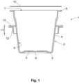
- the Figures 1 to 3 show a container 1 which is designed as a coffee capsule.
- the container 1 has a reservoir 2 and is essentially rotationally symmetrical. It has a base 3 and a peripheral wall 4 surrounding the base 3.
- a central and rotationally symmetrical recess 5 is provided in the base 3 and has a perforation area 6 which is also rotationally symmetrical and centrally arranged therein. The perforation area is pierced by at least one needle in order to allow liquid which is fed into the container 1 under pressure to escape.
- the recess 5 is oriented towards the interior of the container, i.e. towards an opening 7 of the container 2 which is opposite the base 3.
- the container 2 has a flange 8 which surrounds the opening 7 and the peripheral wall 4 in a rotationally symmetrical manner.
- the flange 8 points radially outwards from the peripheral wall 4 and is oriented essentially parallel to the base 3.
- the container 2 with the base 3, the peripheral wall 4 and the flange 8 is formed in one piece from fiber material.
- a primer (not shown) is applied to the inner side 9 of the container 2 facing the inside of the container and to the upward-facing surface of the flange 8.
- the primer can be made of cellulose and casein, for example, and is thus biodegradable. In addition or alternatively, it can also contain other biodegradable Contain ingredients such as whey, agar agar, and/or psyllium husks.
- the primer increases the gas tightness and mechanical stability of the container 2.
- the opening 7 is, as in Figure 1 indicated, covered with a cover 10, which is designed as a sealing film.
- the sealing film 10 is flexible and at the same time gas-tight. It is fixed resting on the flange 8 and thus seals the container interior from the environment.
- the sealing film 10 has the same coating (not shown) on the surface oriented towards the flange 8 as the container interior 9 and the upward-facing surface of the flange 8. The coatings of the sealing film 10 and the flange 8 are firmly bonded to one another.
- the container 1 has an injection-molded connecting element 11 made of a water-soluble and biodegradable thermoplastic.
- the biodegradable thermoplastic can be a thermoplastically processable starch, as described in the publications EP 0 118 240 A2 or EP 0 397 819 B1 described.
- the connecting element is designed as a reinforcement ring 11 with a vertical ring section 12 and a horizontal ring section 13. With the vertical ring section 12, the reinforcement ring 11 rests on the outside against an upper section of the peripheral wall 4.
- recesses 14 are arranged, with which the coffee capsule 1 can be locked in a receiving device of a coffee machine (not shown).
- the vertical ring section 12 can also be designed as a connecting wall with openings and can be embedded in the fiber material during the production of the fiber material molded body (container 2) using the fiber casting process.
- the horizontal ring section 13 protrudes radially outward from an upper end of the vertical ring section 12 beyond the flange 8.
- a radial recess for receiving the flange 8 is formed in the upper end of the horizontal ring section 13.
- the flange 8 and the horizontal ring section 13 are thus complementarily designed, so that the flange 8 and the horizontal ring section 13 end in a common plane at the top. The flange 8 is thus completely enclosed by the horizontal ring section 13 and the sealing film 10.
- the sealing film and the reinforcing ring can be bonded together by an adhesive, preferably a biodegradable adhesive.
- connecting element 11 As an alternative to the form-fitting connection between the connecting element 11 and the container 2 shown here, it is possible to connect the connecting element 11 to the container 2 by injection molding it onto the container.
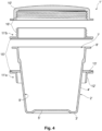
- the Figure 4 shows an alternative embodiment of the container 1' as a jar for holding cosmetic products. Unless otherwise indicated, similar construction elements of the Figure 4 provided with the same reference numerals as already mentioned above and marked with a line to distinguish it from the structural elements of the coffee capsule.
- the crucible 1' also has a container 2' with a base 3', a peripheral wall 4', a central recess 5' in the base 3', an opening 7' opposite the base 3' and a flange 8' pointing radially outwards from the peripheral wall 4'.
- the crucible 1' is essentially rotationally symmetrical.
- a primer made of biodegradable material (not shown here) is also applied to the inside 9' of the container 2', which increases the gas tightness and mechanical stability of the container 2'.
- a cover is designed as a lid 10'.
- a two-part connecting element 11' is positively connected to the container 2'.
- the two-part connecting element 11' is composed of a lower support ring 11'a and an upper threaded ring 11'b. As described above in connection with the coffee capsule 1, the lower support ring 11'a rests on the peripheral wall 4' with a vertical ring section 12' on the outside and on the flange 8' with a horizontal ring section 13'.
- the vertical ring section 12' can also be designed as a connecting wall with openings and embedded in the fiber material during the production of the fiber material molded body (container 2') using the fiber casting process.
- the horizontal ring section 13' protrudes radially beyond the flange 8'.
- the horizontal ring section 13' also has a recess in the end pointing towards the lid 10', into which the flange 8' is received.
- a surface of the flange 8' facing toward the lid 10' and a surface of the horizontal ring section 13' facing toward the lid 10' are located in the same plane.
- the upper threaded ring 11'b has the same outer diameter as the lower support ring 11'a.
- the inner diameter of the upper threaded ring 11'b essentially corresponds to the diameter of the opening 7'.
- the upper threaded ring 11'b is attached to the horizontal ring section 13' of the lower support ring 11'a, which extends radially beyond the flange 8', so that the flange 8' is enclosed by the horizontal ring section 13' of the lower support ring 11'a and by the upper threaded ring 11'b.
- the lower support ring 11'a can, for example, be inserted from below, i.e., via the base 3', over the peripheral wall 4' of the container 2'.
- a tongue and groove connection 15' between the lower support ring 11'a and the upper threaded ring 11'b can form a positive connection.
- the tongue and groove of the tongue and groove connection 15' are locked or glued together. After connection, the lower support ring 11'a and the upper threaded ring 11'b are flush with one another in the radial direction towards the outside.
- the lid 10' can be connected to and detached from the upper threaded ring 11'b via a threaded connection 16'.
- an external thread is provided on the upper threaded ring 11'b and an internal thread on the lid 10'.
- the lid 10' and the upper threaded ring 11'b are screwed together via the thread 16', the lid 10' and the upper threaded ring 11'b are flush radially on the outside, and the interior of the container is sealed gas-tight from the environment.
- the lid 10' is unscrewed from the upper threaded ring 11'b, the interior of the container is connected to the environment through the opening in the upper threaded ring 11'b.
- the Figure 5 shows a further alternative embodiment of the container 1" as a jar for holding cosmetic products. Unless otherwise indicated, similar construction elements of the Figure 5 provided with the same reference numerals as mentioned above and marked with two primes to distinguish it from the other embodiments.
- the crucible 1" also has a container 2" with a base 3", a peripheral wall 4", a central recess 5" in the base 3", an opening 7" opposite the base 3", and a flange 8" pointing radially outward from the peripheral wall 4". In the area of the opening, the container 2" is slightly widened in order to accommodate a connecting element 11".
- the crucible 1" is essentially rotationally symmetrical.
- a primer made of biodegradable material (not shown here) is also applied to the inside 9" of the container 2", which increases the gas tightness and mechanical stability of the container 2".
- the connecting element 11" in the area of the opening 7" is designed in two parts and is connected to the container 2' in a form-fitting and material-fitting manner.
- a cover is also designed in the crucible 1" shown here as a lid 10", which interacts with the connecting element 11".
- the two-part connecting element 11" is composed of an inner support ring 11"a and an outer threaded ring 11"b.
- the inner support ring 11"a has a vertical ring section 12" and a horizontal ring section 13", wherein the horizontal ring section 13" surrounds the vertical ring section 12" approximately halfway up on the outside and at a right angle.
- the vertical ring section 12" has an external thread 16"a.
- the area of the vertical ring section 12" below the horizontal ring section 13" has a substantially smooth-cylindrical outer surface, which complementary to the surface of the expanded area of the container 2". The inner support ring 11"a is thus inserted into the container 2".
- the abutting surfaces are glued together to ensure high tightness and mechanical stability.
- the bonding can also be achieved, for example, by inserting the container 2" and the vertical ring section 12" into one another and pressing them together at a temperature at which the injection-molded material softens or melts. The molten material of the vertical ring section 12" then adheres to the container 2" and possibly penetrates its pores.
- bonding is optional; a secure joint can also be achieved, for example, by a press fit.
- the vertical ring section 12" below the horizontal ring section 13" can also be designed as a connecting wall with openings and embedded in the fiber material of the container wall during the production of the fiber molded body (container 2') using the fiber casting process. Radially on the outside, the horizontal ring section 13" is flush with the flange 8".
- the inner diameter of the upper threaded ring 11'b essentially corresponds to the diameter of the opening 7'.
- the area of the vertical ring section 12" with the external thread 16"a protrudes upwards from the container 2".
- the outer threaded ring 11"b has an internal thread 16"b on the inward-facing side, which is complementary to the external thread 16"a of the inner support ring 11"a.
- the outward-facing surface of the outer threaded ring 11"b is smooth-cylindrical, and its diameter is smaller than the diameter of the horizontal ring section 13".
- the cover 10" has a curved cover surface 10"a and a ring section 10"b surrounding it.
- the inner diameter of the ring section 10"b corresponds to the outer diameter of the outer threaded ring 11"b.
- the cover 10" can be inserted and removed from above onto the outer threaded ring 11"b.
- the lid 10', 10", the lower support ring 11'a, the inner support ring 11"a, the upper threaded ring 11'b and the outer threaded ring 11”b are injection-molded from a water-soluble and compostable thermoplastic.
- the connecting element 11', 11" it is possible to form the connecting element 11', 11" in one piece and/or to connect the connecting element 11', 11" to the container 2', 2" by injection molding.
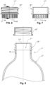
- FIGS. 6 and 7 show a side view and a longitudinal section of another embodiment of a connecting element 11"' and Figure 8 shows a container 1"' designed as a bottle with this connecting element 11"' and a container 2"'.
- the upper section of the connecting element 11"' again has an external thread 16"', onto which a cover 10"' designed as a screw cap can be screwed.
- the container 2"' can, for example, hold a beverage, a dishwashing detergent or another liquid, gel-like or powdery material.
- the container 1"' is tightly closed by the screw cap 10"'.
- the connecting element In order to ensure that the connecting element is connected to the container 2"' in a particularly tight and durable manner, it has a thin annular connecting wall 17 below the external thread 16"', which surrounds the opening 7"' of the container 2"'.
- the connecting wall 17 is provided with a plurality of openings 18, between which webs are located, which form the connecting wall 17.
- the Figures 9 - 11 show an upper section of a multi-part suction mold 19 with a porous wall 20 for producing the container from Fig. 8
- the suction mold 19 has two, three, four, or more parts to enable the removal of the molded body formed in the suction mold 19.
- the porous wall of the suction mold can be achieved in a conventional manner by a base body made of plastic or metal with suction channels, into which a sieve-like structure is inserted, forming the porous wall.
- the porous wall 20 of the suction mold 19 is produced using a 3D printing process, with liquid-permeable channels being embedded in the material of the porous wall 20.
- the suction mold 19 has an upper receiving section 21 for the injection-molded connecting element 11"'.
- the connecting element 11"' is inserted into the receiving section 21 of the suction mold 19 such that the connecting wall 17 of the connecting element 11"' has a small distance d of the order of 1 mm from the porous wall 20 of the suction mold 19.
- the suction mold 19 is then immersed in pulp, and water is sucked off through the porous wall 20, so that a layer of fiber 22 is deposited on the porous wall 20 of the suction mold 19.
- the fiber 22 penetrates through the openings 18 of the connecting wall 17 of the connecting element 11"' and projects through the openings 18.
- the fiber layer of the container 2"' can then be compacted by pressing an inflatable pressing tool (not shown) against the inside of the deposited fiber layer.
- the fiber layer is thereby dewatered and compacted and firmly encloses the webs between the openings 18 in the connecting wall 17.
- the drawings show rotationally symmetrical containers.
- the openings have a circular clear cross-section.
- the person skilled in the art will recognize that the containers and their Openings can have a shape other than circular.
- the containers and their openings can be square.
- the connecting elements also have the shape of a square ring enclosing a square opening.
Landscapes
- Engineering & Computer Science (AREA)
- Mechanical Engineering (AREA)
- Chemical & Material Sciences (AREA)
- Life Sciences & Earth Sciences (AREA)
- Wood Science & Technology (AREA)
- Organic Chemistry (AREA)
- Materials Engineering (AREA)
- Ceramic Engineering (AREA)
- Biodiversity & Conservation Biology (AREA)
- Manufacturing & Machinery (AREA)
- Oil, Petroleum & Natural Gas (AREA)
- Food Science & Technology (AREA)
- Composite Materials (AREA)
- Closures For Containers (AREA)
- Containers Having Bodies Formed In One Piece (AREA)
- Packages (AREA)
- Optical Couplings Of Light Guides (AREA)
- Injection Moulding Of Plastics Or The Like (AREA)
- Paints Or Removers (AREA)
- Biological Depolymerization Polymers (AREA)
- Paper (AREA)
Description
- Die Erfindung betrifft einen Formkörper aus Faserstoff mit einem Anschlusselement.
- Sie bezieht sich insbesondere auf ein Behältnis mit einem mindestens eine Öffnung aufweisenden Behälter aus Faserstoff und einer Abdeckung für die Öffnung, wobei der Behälter eine biologisch abbaubare oder bioinerte Beschichtung aufweist, wobei ein spritzgegossenes Anschlusselement zumindest den Bereich der Öffnung lokal verstärkt. Die Problematik der festen Verbindung eines Anschlusselements mit einem Formkörper aus Faserstoff ist aber nicht auf den Anwendungsfall der lokalen Verstärkung einer Behälteröffnung beschränkt.
- Aus
EP 2 573 008 B1 ist ein Behälter, insbesondere eine Kaffeekapsel, bekannt, der aus einem Papiermaterial gebildet ist und an einem offenen Ende einen Flansch aufweist. An dem Flansch ist ein sich radial über den Flansch hinaus erstreckender Verstärkungsring angeordnet, der mit einer Abdeckung geklebt oder geschweißt werden kann. Der Verstärkungsring ist insbesondere aus Papier oder/und einem anderem Material hergestellt, welches wenigstens ein Harz oder Gummi enthält. - Aus
DE 10 2019 101 545 A1 ist ein Behältnis, insbesondere eine Kaffeekapsel, mit einem becherförmigen Behälter aus Faserstoff bekannt, welcher mittels einer als Deckel bezeichneten Abdeckung verschließbar ist. Der Behälter weist an einer Öffnung einen als ringförmigen Umfangsrand bezeichneten Flansch auf. Der Flansch ist von einem Verstärkungsring umgriffen, welcher insbesondere aus einem unbeschichteten Kartonagenwerkstoff hergestellt ist. - Aus
FR 2 741 042 A1 - Die Druckschrift
US 2010/0252617 A1 beschreibt eine aus Papierpulpe gefertigte Flasche aus Faserstoff mit einem zylindermantelförmigen Halsabschnitt, wobei in oder auf den Halsabschnitt eine ebenfalls zylindermantelförmige Verbindungswandung eines Anschlusselements eingesteckt oder aufgesteckt ist. Das Anschlusselement hat einen Gewindeabschnitt zum Aufschrauben eines Schraubdeckels. Die DruckschriftUS 8 663 419 B2 beschreibt ebenfalls eine aus Pulpe gefertigte Flasche aus Faserstoff mit einem Anschlusselement, dass sowohl eine axial verlaufende Zylinderwandung als auch einen sich daran anschließenden und radial verlaufenden Haltering aufweist, die beide innerhalb der Hülle der Flasche aus Faserstoff verlaufen und dagegen anliegen. - Die aus dem Stand der Technik bekannten Behältnisse sind entweder nicht ausschließlich aus biologisch abbaubaren Bestandteilen gebildet, oder sie weisen eine vergleichsweise geringe mechanische Stabilität auf.
- Die Aufgabe der Erfindung ist es, einen Formkörper aus Faserstoff mit einem Anschlusselement zuverlässig und dauerhaft zu verbinden. Dies kann dem Zweck dienen, ein Behältnis bereitzustellen, das ausschließlich aus biologisch abbaubaren Bestandteilen gebildet ist, das eine hohe Gasdichtigkeit und eine hohe mechanische Stabilität aufweist und dessen Herstellung besonders flexibel und kostengünstig ist. Die hier beschriebene Technologie ist aber auch für jeden anderen Formkörper aus Faserstoff vorteilhaft, der mit einem beliebigen Anschlusselement zu verbinden ist.
- Die Aufgabe wird dadurch gelöst, dass das Anschlusselement eine Verbindungswand mit Durchbrüchen aufweist, welche von dem Faserstoff des Formkörpers durchragt werden.
- Das Anschlusselement kann also eine dünne Verbindungswand aufweisen, in der mehrere Durchbrüche angeordnet sind. Die Durchbrüche sind vorzugsweise regelmäßig über die Fläche der Verbindungswand verteilt. Insbesondere kann die Verbindungswand gitterförmig ausgebildet sein, so dass die Fläche der Durchbrüche etwa gleich groß ist wie oder größer ist als die Fläche der zwischen den Durchbrüchen verbleibenden Stege. Das Anschlusselement kann in eine Saugform eingelegt werden, in der der Formkörper aus Faserstoff geformt wird. Die Saugform wird in eine Pulpe, das heißt in eine Mischung von Faserstoff mit Wasser, eingetaucht. Durch eine poröse Wand der Saugform wird das Wasser angesogen, wobei sich das Fasermaterial in einer Schicht auf der Oberfläche der Saugform ablagert. Die Verbindungswand mit Durchbrüchen wird bei diesem Vorgang in einem geringen Abstand von z.B. 1 mm zu der porösen Wand der Saugform gehalten. Im Bereich der Verbindungswand des Anschlusselements mit Durchbrüchen lagert sich der Faserstoff um die Verbindungswand herum ab und durchragt die Durchbrüche, so dass das Anschlusselement fest in der entstehenden Faserstoffschicht verankert wird, die den Formkörper bildet. Der angesaugte Faserstoff kann gepresst werden, so dass die gebildete Faserstoffschicht mit dem eingeformten Abschnitt des Anschlusselements entwässert wird.
- Das Anschlusselement kann eine beliebige Form aufweisen und eine beliebige Funktion erfüllen. Es kann aus beliebigen, festen Materialien wie Holz oder Leichtmetall gebildet sein, insbesondere aber aus einem biologisch abbaubaren Kunststoff. Zur Verankerung in der Faserstoffschicht des Faserstoff-Formkörpers weist das Anschlusselement einen Abschnitt auf, der als dünne Verbindungswand mit Durchbrüchen ausgebildet ist. Die Verbindungswand kann auf die oben beschriebene Weise in eine Faserstoffschicht des Faserstoff-Formkörpers eingebettet werden.
- Wie eingangs erwähnt, wurde der Formkörper aus Faserstoff ausgehend von einem Behältnis entwickelt. Das Behältnis weist einen mindestens eine Öffnung aufweisenden Behälter aus Faserstoff und eine Abdeckung für die Öffnung auf, wobei der Behälter der erfindungsgemäße Faserstoff-Formkörper sein kann und eine biologisch abbaubare Beschichtung aufweisen kann. Alternativ oder zusätzlich kann der Behälter eine bioinerte Beschichtung, insbesondere eine SiO2-Beschichtung aufweisen, die im Sol-Gel-Prozess auf der Innenseite des Behälters abgelagert wird. Falls der Formkörper aus Faserstoff keine dichtende Funktion hat, kann auf die Beschichtung verzichtet werden.
- Der Förmkörper, d.h. der Behälter, aus Faserstoff, kann, wie oben beschrieben, aus einer wässrigen Pulpe mit Cellulosefasern hergestellt werden. Die Cellulosefasern werden bspw. durch ein einfaches Schöpfverfahren mittels einer Saugform in eine Form gebracht, welche den Formkörper bildet. Dabei wird das Wasser durch Poren in der Saugform abgesaugt und die Cellulosefasern lagern sich auf der mit den Poren versehenen Oberfläche der Saugform ab. Beim Transferverfahren wird der durch die Saugform gebildete Formkörper einer Transferform übergeben, so dass er von beiden Seiten geformt wird. Es können zusätzliche thermische Bearbeitungsverfahren und Pressverfahren zum Einsatz kommen, welche die Oberflächenqualität des Formkörpers erhöhen. Der so gebildete Formkörper aus Faserstoff ist fest und formstabil.
- Der auf diese Weise hergestellte Behälter aus Faserstoff kann eine Öffnung, einen der Öffnung gegenüberliegenden Boden, und eine die Öffnung und den Boden umfassende Umfangswand aufweisen. Die Öffnung und der Boden können beispielsweise rund, oval oder polygonal sein. An der Öffnung des Behälters ist eine Abdeckung angebracht oder anbringbar, durch welche die Öffnung des Behälters verschlossen bzw. verschließbar ist. Die Abdeckung wirkt derart mit dem Behälter zusammen, dass der Innenraum des Behälters gegenüber der Umgebung geschlossen bzw. schließbar ist. Die Abdeckung kann ebenfalls biologisch abbaubar sein.
- Faserstoff ohne eine Beschichtung weist eine gewisse Gas- und Wasserdurchlässigkeit auf. Dies kann bei bestimmten Anwendungsfällen eines Formkörpers erwünscht oder zumindest nicht nachteilig sein. Eine hier beschriebene Ausführungsform eines Behälters aus Faserstoff weist eine biologisch abbaubare Beschichtung auf, so dass seine Gas- und Wasserdichtigkeit erhöht ist, insbesondere wenn die Abdeckung mit dem Behälter zusammenwirkt. Das Beschichten von Faserstoff ist grundsätzlich aus dem Stand der Technik bekannt. Beschichtungen können beispielsweise aufgesprüht werden. Alternativ oder zusätzlich kann eine Beschichtung durch Eintauchen eines Faserstoffs in ein Beschichtungsbad und anschließendes trocknen erfolgen. Zum Beispiel offenbart die Druckschrift
WO 2020/216719 A1 der Anmelderin eine biologisch abbaubare Barriereschicht für ein Cellulosesubstrat, die sich zur Beschichtung der hier beschriebenen Faserstoffbehälter gut eignet. - An dem Behälter kann das Anschlusselement angeordnet sein, welches den Behälter zumindest im Bereich der Öffnung lokal verstärken kann. Der Behälter und das Anschlusselement können somit ein Behältnis bilden, das zumindest im Bereich der Öffnung lokal verstärkt ist. Das Anschlusselement kann spritzgegossen und/oder aus biologisch abbaubarem Material gebildet sein.
- Mit anderen Worten kann ein im Spritzgießverfahren hergestelltes Anschlusselement verwendet werden, das derart mit dem Behälter zusammenwirkt, dass der Behälter zumindest im Bereich der Öffnung besonders steif und formstabil ist. Zu diesem Zweck weist das Material des Anschlusselements eine höhere Festigkeit auf als der Faserstoff, aus dem der Behälter gebildet ist. Das Behältnis kann somit insgesamt höhere mechanische Beanspruchungen aufnehmen als der Behälter ohne ein derartiges Anschlusselement. Da das Anschlusselement aus einem biologisch abbaubaren Material gefertigt sein kann, kann das Behältnis ausschließlich aus biologisch abbaubaren Materialien bestehen. Biologisch abbaubar bedeutet, dass die Materialien unter bestimmten anaeroben oder aeroben Bedingungen zersetzt werden können. Das biologisch abbaubare Material des Anschlusselements kann ferner spritzgießbar sein. Es kann hierfür insbesondere thermoplastisch sein. Damit ist gemeint, dass das Material, aus dem das Anschlusselement gebildet ist, in einem erwärmten Zustand fließfähig ist und erstarrt, wenn es abkühlt. Eine derartige Konsistenzänderung ist bei thermoplastischen Materialien reversibel. Alternativ ist es auch möglich, dass das spritzgießbare Material nur während der Verarbeitung fließfähig ist und in dem spritzgegossenen Zustand in der Art von Duromeren oder Elastomeren irreversibel aushärtet. Es wird explizit darauf hingewiesen, dass das spritzgießbare Material des Anschlusselements zusätzlich oder alternativ auch druckbar, insbesondere 3D-druckbar, und/oder mehrteilig ausgebildet sein kann. Dadurch, dass das Material des Anschlusselements spritzgießbar und/oder druckbar ist, können verschiedene Geometrien kostengünstig mit einer einzigen Produktionsanlage und notwendigenfalls angepassten Werkzeugen hergestellt werden, wodurch die Herstellung des Anschlusselements besonders flexibel und kostengünstig ist.
- In der Praxis eignet sich z.B. eine thermoplastisch verarbeitbare Stärke zur Bildung des Anschlusselements, wie sie in den Druckschriften
EP 0 118 240 A2 oderEP 0 397 819 B1 beschrieben ist. - Wenn das Anschlusselement mehrteilig ist, können verschiedene Teile gemäß einem Baukastenprinzip zu unterschiedlichen Anschlusselementen zusammengesetzt werden, wodurch die Flexibilität und Kosteneffizienz der Herstellung steigt. Insbesondere, wenn das Anschlusselement spritzgegossen ist, ist eine hohe Oberflächengüte des Anschlusselements erzielbar und gut reproduzierbar.
- Das Anschlusselement kann aber auch aus anderen Materialien als spritzgießbaren Materialien bestehen. Durch die vorgeschlagene Verbindungswand mit Durchbrüchen, welche von dem abgelagerten Faserstoff, der den Formkörper bildet, durchragt werden, wird das Anschlusselement fest in der entstehenden Faserstoffschicht verankert und kann beliebige Funktionen erfüllen.
- In der Praxis kann die Beschichtung des Formkörpers, insbesondere des Behälters, eine Grundierung sein, die mindestens einen der folgenden Bestandteile enthält:
- Cellulosefasern,
- Kasein,
- Molke,
- Agar Agar,
- Flohsamenschalen
- SiO2.
- Die Grundierung kann auf die in den Innenraum weisende Oberfläche (die Innenseite) des Behälters aufgebracht sein. Zusätzlich oder alternativ kann die Grundierung auf die nach außen weisende Oberfläche (die Außenseite) des Behälters aufgebracht sein. Wie oben erwähnt, erhöht die Beschichtung die Gasdichtigkeit des Behälters. Zusätzlich kann dadurch auch dessen Festigkeit gesteigert werden.
- Cellulose-Nanofibrillen oder -Mikrofibrillen können beispielsweise in Wasser gelöst sein und auf den Behälter aufsprühbar sein. Nanocellulose weist Cellulose-Microfibrillen mit einem Durchmesser im Median in einem Bereich von 30 bis 100 nm und/oder Cellulose-Nanofibrillen mit einem Durchmesser im Median in einem Bereich von 5 bis 20 nm auf. Dabei sind industriell vertriebene Cellulose-Fibrillen oft ein Gemisch von Microfibrillen und Nanofibrillen. In der Praxis hat sich eine Mischung von 2 Gew.-% Nanocellulose in 98 Gew.-% Wasser für die Grundierung bewährt. Wenn ein höherer Celluloseanteil gewählt wird, kann eine Verformung des Behälters durch die Feuchtigkeit reduziert oder vermieden und die Trocknungszeit der Grundierung verkürzt werden. In der Praxis ist ein Celluloseanteil der Grundierungslösung von 2 bis 10 Gew.-% geeignet.
- Es existieren noch weitere organische Materialien, die in einer Grundierung die Dichtigkeit eines Behälters gegen Gasdurchtritt steigern. Zum Beispiel kann Kaseinpulver mit Wasser gemischt und mittels Calciumhydroxid denaturiert werden. Das Kasein steigert die Dichtigkeit und die mechanische Festigkeit des Behälters. Mit Calciumhydroxid denaturiertes Kasein wird auch in gewissem Maße wasserabweisend. Es ist auch möglich, das Kasein mit Natron zu denaturieren, wobei es aber nicht wasserabweisend wird.
- In der Praxis wurden 30 g Kaseinpulver mit 100 ml Wasser über etwa 8 bis 10 Stunden quellen gelassen, 30 g Calciumhydroxid wurden beigegeben und verrührt. Nach nochmaliger Zugabe von 50 ml Wasser wurde die Lösung gesiebt und zur Grundierung verwendet. Diese Grundierung kann nach der Grundierung mit Cellulosefasern oder alternativ zur Grundierung mit Cellulosefasern aufgebracht werden. Auch kann die Grundierung sowohl Cellulosefasern als auch Kasein enthalten.
- Auch Molke eignet sich als Bestandteil der Grundierung. Molke kann durch Hitze (90°-100°C) denaturiert werden. Auch Molke als Bestandteil der Grundierung steigert die Festigkeit des beschichteten Behälters. Die Molkebeschichtung ist selbst nicht wasserabweisend und muss daher mit einer zweiten Beschichtung wasserdicht gemacht werden.
- Schließlich eignen sich gelbildende Bestandteile wie Agar Agar (Gelatine aus Algen) oder Flohsamenschalen (Samenschalen der Wegericharten Plantago indica, Plantago afra) zur Beimischung zur Grundierung. Agar Agar-Pulver wird z.B. zu diesem Zweck mit Wasser gemischt und für 1 min. bei 100°C denaturiert. Beim Erkalten härtet es aus und geliert. Das Gel kann auf den Behälter aufgetragen werden und bildet eine dünne Schicht, welche die Poren des Faserstoffs verschließt, die Festigkeit steigert und Wasser abweist.
- Ein ähnlicher Effekt wird erreicht, wenn gemahlene Flohsamenschalen in Wasser eingeweicht und nach ca. 20 min Quellen auf den Behälter aufgetragen werden.
- Wie erwähnt, können die Bestandteile der Grundierung gleichzeitig in Wasser gelöst und als Mischung auftragbar sein. Es ist aber auch möglich, die Grundierung als mehrere Lagen mit verschiedenen Bestandteilen auf den Behälter aufzubringen. Alle vorstehend genannten möglichen Bestandteile der Grundierung sind biologisch abbaubar.
- Es kann auch eine Beschichtung aus Siliziumdioxid SiO2 aufgebracht werden, die besonders dicht und widerstandsfähig ist. Je nach der Modifikation beziehungsweise dem Ordnungsgrad des Siliziumdioxids ist dieses nur schlecht wasserlöslich. Auf jeden Fall ist es bioinert, d.h. dass es zu keiner chemischen und/oder biologischen Wechselwirkung zwischen Siliziumdioxid und anderen Stoffen kommt. Diese Beschichtung kann z.B. durch einen Sol-Gel-Prozess an der Innenseite des Behälters abgelagert werden. Die Beschichtung kann entweder nur an dem Behälter oder gleichzeitig an dem Behälter und dem Anschlusselement angebracht werden.
- In der Praxis kann das Material des Anschlusselements wasserlöslich und/oder kompostierbar sein. Wasserlöslich bedeutet, dass sich das Anschlusselement innerhalb einer Woche, bevorzugt innerhalb eines Tages, und besonders bevorzugt innerhalb weniger Stunden, in Wasser auflöst. Dadurch kann das Anschlusselement besonders schnell biologisch abgebaut werden. Kompostierbar ist ein Polymer gemäß der Europäischen Norm EN13432, wenn es in einer industriellen Kompostieranlage, unter anderem, innerhalb von 6 Monaten zu mindestens 90 % durch Mikroorganismen in CO2 umgewandelt wird, wobei in der Ausgangsmasse maximal 1 % Zusatzstoffe enthalten sind, die als unbedenklich eingestuft sind. Vorzugsweise ist nicht nur das Anschlusselement kompostierbar, sondern es sind alle Komponenten, d.h. das Anschlusselement, der Behälter und ggf. die Abdeckung kompostierbar. In der Praxis können alle Komponenten ohne industriell definierte Bedingungen kompostierbar sein. Dadurch ist eine Kompostierung auch ohne industrielle Kompostieranlage möglich. Selbst wenn der Formkörper aus Faserstoff und das Anschlusselement nicht mit dem sortierten Kompost-Müll entsorgt werden, sondern in die Umwelt gelangen, werden sie innerhalb weniger Monate zersetzt. Demgegenüber ist die überwiegende Mehrheit von kompostierbaren Polymeren, darunter häufig verwendete Polylactide, meist nur bei industriell definierten Bedingungen oder über lange Zeiträume von mehreren Jahren biologisch abbaubar. Der ökologische Fußabdruck des Formkörpers aus Faserstoff und des Anschlusselements sind gegenüber Behältnissen aus vielen anderen Materialien bei ähnlicher mechanischer Stabilität somit erheblich minimiert.
- Durch die Verbindungswand mit Durchbrüchen kann eine besonders stabile formschlüssige Verbindung erreicht werden. Wenn der Formkörper aus Faserstoff als Behälter mit einer Öffnung ausgebildet ist und das Anschlusselement eine die Öffnung des Behälters umgebende Verbindungswand mit Durchbrüchen aufweist, welche von dem Faserstoff des Behälters durchragt werden, wird das Anschlusselement im Bereich der Öffnung verankert. Das Anschlusselement kann eine ringförmige dünne Verbindungswand aufweisen, in der Durchbrüche angeordnet sind. Insbesondere kann die Verbindungswand gitterförmig ausgebildet sein, so dass die Fläche der Durchbrüche etwa gleich groß ist wie oder größer als die Fläche der zwischen den Durchbrüchen verbleibenden Stege. Das Anschlusselement kann in eine Saugform eingelegt werden, in der der Behälter aus Faserstoff geformt wird. Die Verbindungswand hat dann einen geringen Abstand von z.B. 1 mm zu einer porösen Wand der Saugform. Aus einer Pulpe kann durch die poröse Wand der Saugform hindurch Wasser abgesaugt werden, so dass sich der Faserstoff auf der porösen Wand der Saugform ablagert. Im Bereich der Verbindungswand des Anschlusselements mit Durchbrüchen durchragt der abgelagerte Faserstoff die Durchbrüche und verankert so das Anschlusselement fest in der entstehenden Faserstoffschicht, die den Behälter bildet. Wenn der angesaugte Faserstoff gepresst wird, kann das Pressen beispielsweise durch ein aufblasbares Presswerkzeug erfolgen, das gegen die Innenseite des geformten Faserstoffbehälters gedrückt wird und so die Behälterwand aus Faserstoff mit dem eingeformten Abschnitt des Anschlusselements entwässert.
- Ferner kann der Faserstoff-Formkörper bei einer Temperatur mit dem Anschlusselement verpresst werden, bei der im Falle eines thermoplastischen Anschlusselements das spritzgegossene Material erweicht oder an seiner Oberfläche aufschmilzt und in die Poren des Faserstoffs eindringt.
- Wenn der Faser-Formkörper und das Anschlusselement ein Behältnis mit einer Abdeckung bilden, kann die Abdeckung des Behältnisses in der Praxis als Siegelfolie ausgebildet sein. Siegelfolien können aus dicht beschichtetem Faserstoff bestehen. Sie sind dünn, flexibel und gleichzeitig gasdicht. Die Beschichtung der Siegelfolie kann insbesondere identisch mit der Beschichtung des Behälters sein. Sie kann aber auch eine andere Zusammensetzung aufweisen. Wenn die Beschichtung der Abdeckung mit der Beschichtung des Behälters identisch ist und/oder diese beiden Beschichtungen durch das gleiche Lösungsmittel lösbar sind, können der Behälter und die Abdeckung durch stoffschlüssiges Fügen besonders einfach und sicher miteinander verbunden werden. Beispielsweise kann die beschichtete und noch nicht vollständig getrocknete Abdeckung derart an die Öffnung des Behälters gelegt werden, dass die Öffnung vollständig abgedeckt ist. Der Behälter und die Abdeckung können dann aneinandergepresst werden, wobei die Beschichtung des Behälters angelöst wird und später in Verbindung mit der Beschichtung der Abdeckung trocknet. Durch eine derartige Abdeckung und Verbindung weist das Behältnis einen minimalen Materialverbrauch und nur wenige verschiedene Materialien auf, was für die biologische Abbaubarkeit und/oder Kompostierbarkeit vorteilhaft ist.
- Zusätzlich oder alternativ kann die Abdeckung aus dem gleichen Material gebildet sein wie das Anschlusselement. In diesem Fall kann die Abdeckung ein Deckel, insbesondere ein Schraubdeckel, sein. Ein Deckel deckt die Öffnung des Behälters ab, ist von der Öffnung lösbar und kann wieder angebracht werden. Hierfür ist der Deckel formschlüssig mit dem Behälter und/oder mit dem Anschlusselement verbunden, beispielsweise indem der Deckel mit einem Innengewinde auf ein Außengewinde des Behälters oder des Anschlusselements aufgeschraubt wird. Natürlich kann die formschlüssige Verbindung auch durch andere konstruktive Maßnahmen, die hierfür geeignet sind, erfolgen, wie zum Beispiel Rastvorsprünge und komplementäre Aufnahmen oder einen Bayonettverschluss. Wenn die Abdeckung wie das Anschlusselement aus spritzgegossenem Material besteht, weist das Behältnis eine besonders hohe Festigkeit und Dichtigkeit auf.
- Natürlich kann das Behältnis auch eine Mehrzahl von Abdeckungen, beispielsweise eine oben beschriebene Siegelfolie und zusätzlich einen darüber angeordneten, mit dem Behälter oder dem Anschlusselement verschraubbaren Deckel aufweisen.
- In der Praxis kann die oben beschriebene Grundierung eine erste Beschichtung sein und der Formkörper/Behälter kann eine zweite zumindest lokal aufgetragene Beschichtung aufweisen. Die zweite Beschichtung kann auf die Grundierung aufgetragen sein. Wenn die Grundierung nur auf einer Seite des Behälters, also entweder der Innenseite oder der Außenseite, aufgetragen ist, ist es auch möglich, dass die zweite Beschichtung zusätzlich oder alternativ auf derjenigen Seite des Behälters aufgetragen ist, auf der die Grundierung nicht aufgetragen ist. Durch die zweite Beschichtung kann die Gasdichtigkeit und/oder die Festigkeit des Behälters erhöht werden. Insbesondere kann die zweite Beschichtung derart auf dem Behälter aufgebracht sein, dass die Festigkeit des Behälters zumindest in einem Bereich erhöht ist, in welchem das Anschlusselement und/oder die Abdeckung angeordnet sind. In einem derartigen Bereich kann der Behälter aufgrund der erhöhten Festigkeit eine hohe oder zyklische Belastung durch das Anschlusselement und/oder die Abdeckung besonders gut aufnehmen.
- Die zweite Beschichtung kann in der Praxis aus Leinöl, Carnaubawachs und/oder Bienenwachs, also aus natürlichen Wachsen und/oder Ölen bzw.
- Fetten, gebildet sein. Natürliche Wachse und/oder Lipide bestehen überwiegend aus Estern von Fettsäuren und sind als öllösliche Produkte nach dem Testverfahren CEC-L-33-A-93 gut biologisch abbaubar.
- Leinöl dient der verbesserten Formbarkeit des Öl-Wachs-Gemischs, welches die zweite Beschichtung bildet, und der Minimierung der Brüchigkeit nach dem Trocknen. Es sollte pharmazeutisches, also vollkommen geklärtes reines Leinöl verwendet werden. Leinöl ist eines der wenigen härtenden Öle und wird seit Jahrhunderten für die Holzimprägnierung benutzt. Eine Leinölschicht allein ist aber offenporig, lässt also Wasser und Luft zum Teil durch, und eignet sich nicht zur dauerhaft dichten Verpackung von Lebensmitteln.
- Carnaubawachs ist ein sehr hartes, tropisches Wachs mit hoher Schmelztemperatur (ca. 85-89°C). Es hat kaum Eigengeruch oder Eigengeschmack und ist wasserdicht. Es ist im trockenen Zustand sehr brüchig, härtet innerhalb von Sekunden aus. Durch seine Härte ist es zudem sehr stabil gegen Abrieb. Es ist für die Verpackung von Lebensmitteln zugelassen und wird seit langem auch als Überzug zur Steigerung der Haltbarkeit von z.B. Mangos, Süßigkeiten etc. eingesetzt.
- Bienenwachs ist ein u.a. in Europa erzeugtes Wachs, das weniger hart als Carnaubawachs ist. In einer Mischung mit Carnaubawachs trägt Bienenwachs zur Verringerung der Brüchigkeit bei. Es hat kaum Eigengeruch oder Eigengeschmack und ist ebenfalls zur Verwendung in Verbindung mit Lebensmitteln zugelassen. Sein Schmelzpunkt liegt bei ca. 65°C.
- In der Praxis kann das Anschlusselement als Verstärkungsring ausgebildet sein. Der Verstärkungsring kann einen in axialer Richtung länglichen Abschnitt in der Art einer Manschette oder eines Rohrabschnitts aufweisen. Der längliche Abschnitt kann beispielsweise die Verbindungswand mit Durchbrüchen bilden. Der Verstärkungsring kann mit dem länglichen Abschnitt insbesondere in der Umfangswand des Behälters eingebettet sein. Dadurch hat das Anschlusselement einen festeren Sitz am Behälter.
- In der Praxis kann der Behälter einen Flansch aufweisen. Der Flansch ist integral mit dem Behälter aus beschichtetem Faserstoff gebildet. Insbesondere kann der Flansch die Umfangswand im Bereich der Öffnung umlaufen. Hierdurch steht eine große Fläche zur Verfügung, an welche die Abdeckung angebracht werden kann.
- Wenn der Behälter den Flansch aufweist und das Anschlusselement als Verstärkungsring ausgebildet ist, kann der Verstärkungsring ferner an einer zum Boden des Behälters weisenden Seite des Flansches oder einer dieser gegenüberliegenden (also einer nach oben weisenden) Seite des Flansches anliegen. Derartige Ausbildungen des Faserformkörpers und des Anschlusselements sind besonders gut als beispielsweise Getränkepulver-Portionsverpackung, insbesondere als eine Kaffeekapsel, geeignet. Durch den Verstärkungsring sind der Flansch und der daran angrenzende Bereich des Behälters mechanisch verstärkt. Eine derartige Verstärkung ist bei Kaffeekapseln mit einem Behälter aus Faserstoff besonders vorteilhaft, da ein Greif-Mechanismus von Kaffeemaschinen für Kaffeekapseln an dem Flansch angreift, um die Kaffeekapsel aus einer ersten Position in eine zweite Position zu bewegen. Der Verstärkungsring am Flansch verleiht den Kaffeekapseln aus Faserstoff die hierfür erforderliche Festigkeit.
- Eine Kaffee-Portionsverpackung in Gestalt einer Kapsel bestehend aus dem hier beschriebenen Faserformkörper mit Anschlusselement hat eine hohe Dichtigkeit, die sehr viel höher als bei gängigen Kaffee-Pads aus unbeschichteten Cellulosefasern ist, und eine bessere Umweltverträglichkeit als gängige Kaffeekapseln aus Aluminium. Folglich kann man den Kaffee lange aufbewahren, ohne viel Müll zu produzieren. Die hier beschriebene Kaffeekapsel besteht allein aus natürlichen Rohstoffen und kann hervorragend biologisch abgebaut und/oder kompostiert werden.
- Natürlich ist es auch möglich, den Faserformkörper mit dem Anschlusselement wie oben beschrieben als ein Behältnis mit einem wiederverschließbaren Schraubverschluss auszubilden und diesen mit Kosmetika, bspw. Cremes, oder mit unverderblichen Produkten, bspw. Schrauben, zu befüllen.
- Die Erfindung betrifft auch ein Verfahren zur Herstellung eines Formkörpers mit Anschlusselement gemäß den Ansprüchen 8 bis 12. Im Falle eines Behältnisses mit einem Behälter aus Faserstoff, einer Abdeckung und einer biologisch abbaubaren Beschichtung kann das an dem Behälter angeordnete Anschlusselement aus biologisch abbaubarem Material bestehen und den Behälter zumindest lokal verstärken. Das Verfahren kann mindestens einen der folgenden Verfahrensschritte umfassen:
- Ansaugen von Fasermaterial aus einer Pulpe durch eine Saugform und Verdichten des Fasermaterials zu dem Behälter;
- Entwässern und Trocknen des Behälters;
- Beschichten des Behälters mit einer Grundierung;
- Herstellen, insbesondere Spritzgießen des Anschlusselements;
- Anbringen der Abdeckung.
- In Bezug auf Einzelheiten der jeweiligen Verfahrensschritte wird auf die obige Beschreibung zu den damit erzeugten Merkmalen verwiesen. Die in Zusammenhang mit diesen Merkmalen genannten Vorteile gelten für das Verfahren entsprechend.
- Wie oben bereits beschrieben, kann, wenn der Formkörper einen Behälter bildet, der Behälter zwei Beschichtungen aufweisen. Die zweite Beschichtung kann insbesondere durch Eintauchen des Behälters in ein Warmbad aus natürlichen Wachsen und/oder Ölen bzw. Fetten erfolgen. Anschließend kann der getränkte Behälter warmgepresst und abgekühlt werden. Durch das Warmpressen des getränkten Behälters wird seine Geometrie fixiert und die zweite Beschichtung kann in nicht gefüllte Poren des Faserstoffs eindringen.
- Weitere praktische Ausführungsformen und Vorteile der Erfindung sind nachfolgend im Zusammenhang mit den Zeichnungen beschrieben. Es zeigen:
- Fig. 1
- ein Behältnis in einer ersten Ausführungsform als Kaffeekapsel in einer vertikal geschnittenen Explosionsdarstellung ohne Verbindungswand mit Durchbrüchen;
- Fig. 2
- das Behältnis aus
Fig. 1 ohne Abdeckung in einer Ansicht von schräg oben; - Fig. 3
- das Behältnis aus
Fig. 1 in einer Ansicht von schräg unten; - Fig. 4
- das Behältnis in einer zweiten Ausführungsform als Tiegel für Kosmetikprodukte in einer vertikal geschnittenen Explosionsdarstellung, ebenfalls ohne Verbindungswand mit Durchbrüchen;
- Fig. 5
- das Behältnis in einer dritten Ausführungsform als Tiegel für Kosmetikprodukte in einer vertikal geschnittenen Explosionsdarstellung, wiederum ohne Verbindungswand mit Durchbrüchen;
- Fig. 6
- ein Anschlusselement mit Verbindungswand und Durchbrüchen für einen als Behälter ausgebildeten Formkörper aus Faserstoff in der Seitenansicht;
- Fig. 7
- eine entlang der Schnittlinie VII - VII geschnittene Ansicht des Anschlusselements aus
Fig. 6 ; - Fig. 8
- eine als Flasche ausgebildete Ausführungsform eines Faserformkörpers mit dem Anschlusselement aus den
Figuren 6 und 7 mit Abdeckung; - Fig. 9
- eine vergrößerte Draufsicht auf einen Abschnitt einer Saugform zur Herstellung der Flasche aus
Fig. 8 ; - Fig. 10
- der Abschnitt der Saugform aus
Fig. 9 mit eingelegtem Anschlusselement aus denFig. 6 und 7 aus spritzgegossenem Material; - Fig. 11
- der Abschnitt der Saugform aus
Fig. 9 mit eingelegtem Anschlusselement und angesaugter Faserstoffschicht. - Die
Figuren 1 bis 3 zeigen ein Behältnis 1, das als Kaffeekapsel ausgebildet ist. Das Behältnis 1 weist einen Behälter 2 auf und ist im Wesentlichen rotationssymmetrisch. Es weist einen Boden 3 und eine den Boden 3 umfassende Umfangswand 4 auf. In dem Boden 3 ist eine zentrale und rotationssymmetrische Vertiefung 5 mit einem darin ebenfalls rotationssymmetrisch und zentral angeordneten Perforationsbereich 6 eingebracht. Der Perforationsbereich wird von mindestens einer Nadel durchstochen, um das Austreten von unter Druck in das Behältnis 1 zugeführter Flüssigkeit zu ermöglichen. Die Vertiefung 5 ist in Richtung des Behälterinneren orientiert, d.h. in Richtung einer dem Boden 3 gegenüberliegenden Öffnung 7 des Behälters 2. An der Öffnung 7 weist der Behälter 2 einen die Öffnung 7 und die Umfangswand 4 rotationssymmetrisch umfassenden Flansch 8 auf. Der Flansch 8 weist von der Umfangswand 4 in radialer Richtung nach außen und ist im Wesentlichen parallel zum Boden 3 orientiert. - Der Behälter 2 mit dem Boden 3, der Umfangswand 4 und dem Flansch 8 ist einteilig aus Faserstoff gebildet. Auf der in das Behälterinnere weisenden Innenseite 9 des Behälters 2 und auf der nach oben weisenden Oberfläche des Flansches 8 ist eine Grundierung (nicht dargestellt) aufgebracht. Die Grundierung kann beispielsweise aus Cellulose und Casein gebildet sein und ist somit biologisch abbaubar. Sie kann zusätzlich oder alternativ aber auch andere biologisch abbaubare Bestandteile, beispielsweise Molke, Agar Agar und/oder Flohsamenschalen, beinhalten. Die Grundierung erhöht die Gasdichtigkeit und die mechanische Stabilität des Behälters 2.
- Die Öffnung 7 ist, wie in
Figur 1 angedeutet, mit einer Abdeckung 10 abgedeckt, welche als Siegelfolie ausgebildet ist. Die Siegelfolie 10 ist flexibel und gleichzeitig gasdicht. Sie ist auf dem Flansch 8 aufliegend fixiert und verschließt somit den Behälterinnenraum gegenüber der Umgebung. Für die Fixierung auf dem Flansch weist die Siegelfolie 10 auf der in Richtung des Flansches 8 orientierten Oberfläche die gleiche Beschichtung (nicht dargestellt) auf wie die Behälterinnenseite 9 und die nach oben weisende Oberfläche des Flansches 8. Die Beschichtungen der Siegelfolie 10 und des Flansches 8 sind stoffschlüssig miteinander verbunden. - Im Bereich der Öffnung 7 weist das Behältnis 1 ein spritzgegossenes Anschlusselement 11 auf, das aus einem wasserlöslichen und biologisch abbaubaren Thermoplast gebildet ist. Das biologisch abbaubare Thermoplast kann eine thermoplastisch verarbeitbare Stärke sein, wie sie in den Druckschriften
EP 0 118 240 A2 oderEP 0 397 819 B1 beschrieben ist. Das Anschlusselement ist als Verstärkungsring 11 mit einem vertikalen Ringabschnitt 12 und einem horizontalen Ringabschnitt 13 ausgebildet. Mit dem vertikalen Ringabschnitt 12 liegt der Verstärkungsring 11 außenseitig an einem oberen Abschnitt der Umfangswand 4 an. An dem vertikalen Ringabschnitt 12 sind, wie in Figur 3 gut zu erkennen, Aussparungen 14 angeordnet, mit denen die Kaffeekapsel 1 in einer Aufnahmevorrichtung einer Kaffeemaschine (nicht dargestellt) arretiert werden kann. Der vertikale Ringabschnitt 12 kann auch als Verbindungswand mit Durchbrüchen ausgebildet sein und bei der Herstellung des Faserstoff-Formkörpers (Behälter 2) im Fasergussverfahren in den Faserstoff eingebettet werden. - Der horizontale Ringabschnitt 13 ragt von einem oberen Ende des vertikalen Ringabschnitts 12 in radialer Richtung nach außen über den Flansch 8 hinausgehend hervor. In dem horizontalen Ringabschnitt 13 ist in das obere Ende eine radiale Aussparung zur Aufnahme des Flansches 8 ausgebildet. Der Flansch 8 und der horizontale Ringabschnitt 13 sind also komplementär gestaltet, so dass der Flansch 8 und der horizontale Ringabschnitts 13 oberseitig in einer gemeinsamen Ebene abschließen. Der Flansch 8 ist folglich vollständig durch den horizontalen Ringabschnitt 13 und die Siegelfolie 10 eingeschlossen.
- Die Siegelfolie und der Verstärkungsring können durch einen Klebstoff, vorzugsweise einen biologisch abbaubaren Klebstoff, miteinander verbunden sein.
- Alternativ zu der hier dargestellten formschlüssigen Verbindung zwischen dem Anschlusselement 11 und dem Behälter 2 ist es möglich, das Anschlusselement 11 durch Anspritzen an den Behälter 2 stoffschlüssig mit diesem zu verbinden.
- Die
Figur 4 zeigt eine alternative Ausführungsform des Behältnisses 1' als ein Tiegel zur Aufnahme von Kosmetikprodukten. Sofern nicht anders indiziert, sind gleichartige Konstruktionselemente derFigur 4 mit gleichen Bezugszeichen versehen wie bereits oben genannt und zur Abgrenzung von den Konstruktionselementen der Kaffeekapsel mit einem Strich versehen. Der Tiegel 1' weist ebenfalls einen Behälter 2' mit einem Boden 3', einer Umfangswand 4', einer zentralen Vertiefung 5' im Boden 3', einer dem Boden 3' gegenüberliegenden Öffnung 7' sowie einem von der Umfangswand 4' radial nach außen weisenden Flansch 8' auf. Der Tiegel 1' ist im Wesentlichen rotationssymmetrisch. Auf der Innenseite 9' des Behälters 2' ist ebenfalls eine hier nicht dargestellte Grundierung aus biologisch abbaubarem Material aufgebracht, die die Gasdichtigkeit und die mechanische Stabilität des Behälters 2' erhöht. - Eine Abdeckung ist bei dem hier gezeigten Tiegel 1' als Deckel 10' ausgebildet. Zur Anbringung des Deckels 10' an dem Behälter 2' und zur Verstärkung des Behälters 2' im Bereich der Öffnung 7' ist ein zweiteiliges Anschlusselement 11' formschlüssig mit dem Behälter 2' verbunden.
- Das zweiteilige Anschlusselement 11' ist zusammengesetzt aus einem unteren Stützring 11'a und einem oberen Gewindering 11'b. Der untere Stützring 11'a liegt wie oben im Zusammenhang mit der Kaffeekapsel 1 beschrieben, an der Umfangswand 4' mit einem vertikalen Ringabschnitt 12' außenseitig und an dem Flansch 8' mit einem horizontalen Ringabschnitt 13' an. Der vertikale Ringabschnitt 12' kann auch als Verbindungswand mit Durchbrüchen ausgebildet sein und bei der Herstellung des Faserstoff-Formkörpers (Behälter 2') im Fasergussverfahren in den Faserstoff eingebettet werden. Der horizontale Ringabschnitt 13' ragt radial über den Flansch 8' hervor. Auch der horizontale Ringabschnitt 13' weist in dem in Richtung des Deckels 10' weisenden Ende eine Aussparung auf, in die der Flansch 8' aufgenommen ist. Somit befinden sich eine in Richtung des Deckels 10' weisende Oberfläche des Flansches 8' und eine in Richtung des Deckels 10' weisende Oberfläche des horizontalen Ringabschnitts 13' in derselben Ebene. Der obere Gewindering 11'b weist denselben Außendurchmesser auf wie der untere Stützring 11'a. Der Innendurchmesser des oberen Gewinderings 11'b entspricht im Wesentlichen dem Durchmesser der Öffnung 7'. Der obere Gewindering 11'b ist an dem sich über den Flansch 8' radial hinaus erstreckenden horizontalen Ringabschnitt 13' des unteren Stützrings 11'a befestigt, so dass der Flansch 8' von dem horizontalen Ringabschnitt 13' des unteren Stützrings 11'a und von dem oberen Gewindering 11'b umschlossen ist. Zum Anbringen des zweiteiligen Anschlusselements 11' an dem Behälter 2' kann beispielsweise der untere Stützring 11'a von unten, also über den Boden 3', über die Umfangswand 4' des Behälters 2' geschoben werden, bis der untere Stützring 11'a in Anlage mit dem Flansch 8' ist und der obere Gewindering 11'b kann von oben auf den Flansch 8' und den unteren Stützring 11'a gedrückt werden. Dabei kann eine Nut-Feder-Verbindung 15' zwischen dem unteren Stützring 11'a und dem oberen Gewindering 11'b eine formschlüssige Verbindung eingehen. Dabei sind die Nut und die Feder der Nut-Feder-Verbindung 15' miteinander verrastet oder verklebt. Nach dem Verbinden schließen der untere Stützring 11'a und der obere Gewindering 11'b in radialer Richtung nach außen bündig miteinander ab.
- Der Deckel 10' kann über eine Gewindeverbindung 16' mit dem oberen Gewindering 11'b verbunden und wieder gelöst werden. Dafür ist an dem oberen Gewindering 11'b ein Außengewinde und an dem Deckel 10' ein Innengewinde angeordnet. Wenn der Deckel 10' und der obere Gewindering 11'b über das Gewinde 16' verschraubt sind, schließen der Deckel 10' und der obere Gewindering 11'b radial außen bündig ab und das Behälterinnere ist gasdicht gegenüber der Umgebung verschlossen. Wenn der Deckel 10' von dem oberen Gewindering 11'b abgeschraubt ist, steht das Behälterinnere durch die Öffnung des oberen Gewinderings 11'b mit der Umgebung in Verbindung.
- Die
Figur 5 zeigt eine weitere alternative Ausführungsform des Behältnisses 1" als ein Tiegel zur Aufnahme von Kosmetikprodukten. Sofern nicht anders indiziert, sind gleichartige Konstruktionselemente derFigur 5 mit gleichen Bezugszeichen versehen wie oben genannt und zur Abgrenzung von den anderen Ausführungsformen mit zwei Strichen versehen. Der Tiegel 1" weist ebenfalls einen Behälter 2" mit einem Boden 3", einer Umfangswand 4", einer zentralen Vertiefung 5" im Boden 3", einer dem Boden 3" gegenüberliegenden Öffnung 7" sowie einem von der Umfangswand 4" radial nach außen weisenden Flansch 8" auf. Im Bereich der Öffnung ist der Behälter 2" leicht aufgeweitet, um ein Anschlusselement 11" aufnehmen zu können. Der Tiegel 1" ist im Wesentlichen rotationssymmetrisch. Auf der Innenseite 9" des Behälters 2" ist ebenfalls eine hier nicht dargestellte Grundierung aus biologisch abbaubarem Material aufgebracht, die die Gasdichtigkeit und die mechanische Stabilität des Behälters 2" erhöht. Das Anschlusselement 11" im Bereich der Öffnung 7" ist zweiteilig ausgebildet und formschlüssig sowie stoffschlüssig mit dem Behälter 2' verbunden. Eine Abdeckung ist auch bei dem hier gezeigten Tiegel 1" als Deckel 10" ausgebildet, welcher mit dem Anschlusselement 11" zusammenwirkt. - Das zweiteilige Anschlusselement 11" ist zusammengesetzt aus einem inneren Stützring 11"a und einem äußeren Gewindering 11"b. Der innere Stützring 11"a weist einen vertikalen Ringabschnitt 12" und einen horizontalen Ringabschnitt 13" auf, wobei der horizontale Ringabschnitt 13" den vertikalen Ringabschnitt 12" ca. auf halber Höhe außenseitig und rechtwinklig umgreift. An dem Bereich oberhalb des horizontalen Ringabschnitts 13" weist der vertikale Ringabschnitt 12" ein Außengewinde 16"a auf. Der Bereich des vertikalen Ringabschnitts 12" unterhalb des horizontalen Ringabschnitts 13" weist eine im Wesentlichen glatt-zylindrischen äußeren Oberfläche auf, die komplementär zu der Oberfläche des aufgeweiteten Bereichs des Behälters 2" ist. Der innere Stützring 11"a ist somit in den Behälter 2" eingesetzt. Er liegt mit dem vertikalen Ringabschnitt 12" an der Umfangswand 4" innenseitig und mit dem horizontalen Ringabschnitt 13" an dem Flansch 8" oberseitig an. Die aneinander anliegenden Oberflächen sind miteinander verklebt, um eine hohe Dichtigkeit und mechanische Stabilität zu gewährleisten. Das Verkleben kann zum Beispiel auch dadurch erreicht werden, dass der Behälter 2" und der vertikale Ringabschnitt 12" ineinandergefügt und bei einer Temperatur, bei der das spritzgegossene Material erweicht oder schmilzt, miteinander verpresst werden. Das aufgeschmolzene Material des vertikalen Ringabschnitts 12" haftet dann an dem Behälter 2" und dringt ggf. in seine Poren ein. Das Verkleben ist jedoch optional, eine sichere Fügung kann beispielsweise auch durch eine Presspassung erzielt werden. Alternativ zum Einsetzten des inneren Stützrings 11"a in den Behälter 2" kann der vertikale Ringabschnitt 12" unterhalb des horizontalen Ringabschnitts 13" auch als Verbindungswand mit Durchbrüchen ausgebildet sein und bei der Herstellung des Faserstoff-Formkörpers (Behälter 2') im Fasergussverfahren in den Faserstoff der Behälterwand eingebettet werden. Radial außenseitig schließt der horizontale Ringabschnitt 13" bündig mit dem Flansch 8" ab. Der Innendurchmesser des oberen Gewinderings 11'b entspricht im Wesentlichen dem Durchmesser der Öffnung 7'. Der Bereich des vertikalen Ringabschnitts 12" mit dem Außengewinde 16"a ragt von dem Behälter 2" nach oben hervor.
- Der äußere Gewindering 11"b weist auf der nach innen weisenden Seite ein Innengewinde 16"b auf, das komplementär zu dem Außengewinde 16"a des inneren Stützrings 11"a ausgebildet ist. Der nach außen weisende Oberfläche des äußeren Gewinderings 11"b ist glatt-zylindrisch und sein Durchmesser ist kleiner als der Durchmesser des horizontalen Ringabschnitts 13". Somit ragt der horizontale Ringabschnitt 13", wenn der äußere Gewindering 11"b auf den inneren Stützring 11"a aufgeschraubt ist, radial über den äußeren Gewindering 11"b hinaus.
- Der Deckel 10" weist eine gewölbte Deckfläche 10"a und einen diese umgreifenden Ringabschnitt 10"b auf. Der Innendurchmesser des Ringabschnitts 10"b entspricht dem Außendurchmesser des äußeren Gewinderings 11"b. Somit kann der Deckel 10" von oben auf den äußeren Gewindering 11"b gesteckt und wieder gelöst werden.
- Vorliegend sind der Deckel 10', 10", der untere Stützring 11'a, der innere Stützring 11"a, der obere Gewindering 11'b und der äußere Gewindering 11"b aus einem wasserlöslichen und kompostierbaren Thermoplast spritzgegossen. Alternativ zu der hier dargestellten formschlüssigen Verbindung zwischen dem zweiteiligen Anschlusselement 11', 11" und dem Behälter 2', 2" ist es möglich, das Anschlusselement 11', 11" einteilig auszubilden und/oder das Anschlusselement 11', 11" durch Anspritzen an den Behälter 2', 2" stoffschlüssig mit diesem zu verbinden.
- Die
Figuren 6 und 7 zeigen eine Seitenansicht und einen Längsschnitt einer weiteren Ausführungsform eines Anschlusselements 11"' undFigur 8 zeigt ein als Flasche ausgebildetes Behältnis 1"' mit diesem Anschlusselement 11"' und einem Behälter 2"'. Der obere Abschnitt des Anschlusselements 11‴ weist wieder ein Außengewinde 16"' auf, auf das eine als Schraubdeckel ausgebildete Abdeckung 10"' aufgeschraubt werden kann. Der Behälter 2‴ kann beispielsweise ein Getränk, ein Spülmittel oder ein sonstiges flüssiges, gelförmiges oder pulverförmiges Material aufnehmen. Das Behältnis 1‴ wird durch den Schraubdeckel 10"' dicht verschlossen. Damit das Anschlusselement besonders dicht und haltbar mit dem Behälter 2"' verbunden ist, weist es unterhalb des Außengewindes 16‴ eine dünne ringförmige Verbindungswand 17 auf, welche die Öffnung 7"' des Behälters 2"' umgibt. Die Verbindungswand 17 ist mit einer Vielzahl von Durchbrüchen 18 versehen, zwischen denen sich Stege befinden, welche die Verbindungswand 17 bilden. - Die
Figuren 9 - 11 zeigen einen oberen Abschnitt einer mehrteiligen Saugform 19 mit einer porösen Wand 20 zur Herstellung des Behälters ausFig. 8 . Die Saugform 19 weist zwei, drei vier oder mehr Teile auf, um die Entnahme des in der Saugform 19 gebildeten Formkörpers zu ermöglichen. Die poröse Wand der Saugform kann auf herkömmliche Weise durch einen Grundkörper aus Kunststoff oder Metall mit Absaugkanälen erzielt werden, in den eine siebartige Struktur eingelegt wird, welche die poröse Wand bildet. Bei der dargestellten Ausführungsform wird die poröse Wand 20 der Saugform 19 im 3D-Druckverfahren hergestellt, wobei in das Material der porösen Wand 20 flüssigkeitsdurchlässige Kanäle eingebettet werden. - Die Saugform 19 weist einen oberen Aufnahmeabschnitt 21 für das spritzgegossene Anschlusselement 11"' auf. Für die Herstellung des Faserstoff-Behälters 2‴ wird das Anschlusselement 11"' in den Aufnahmeabschnitt 21 der Saugform 19 so eingelegt, dass die Verbindungswand 17 des Anschlusselements 11"' einen geringen Abstand d in der Größenordnung von 1 mm von der porösen Wand 20 der Saugform 19 hat. Die Saugform 19 wird anschließend in Pulpe getaucht und durch die poröse Wand 20 wird Wasser abgesaugt, so dass sich eine Schicht aus Faserstoff 22 auf der porösen Wand 20 der Saugform 19 ablagert. Dabei dringt der Faserstoff 22 durch die Durchbrüche 18 der Verbindungswand 17 des Anschlusselements 11‴ und durchragt die Durchbrüche 18.
- In der Praxis kann anschließend die Faserstoffschicht des Behälters 2"' verdichtet werden, indem ein aufblasbares Presswerkzeug (nicht dargestellt) gegen die Innenseite der abgelagerten Faserschicht gedrückt wird. Die Faserschicht wird dabei entwässert und verdichtet und schließt die Stege zwischen den Durchbrüchen 18 in der Verbindungswand 17 fest ein.
- In den Zeichnungen sind rotationssymmetrische Behältnisse dargestellt. Die Öffnungen weisen einen kreisförmigen lichten Querschnitt auf. Der Fachmann erkennt, dass die Behältnisse und ihre Öffnungen eine von der Kreisform abweichende Form aufweisen können. Die Behälter und ihre Öffnungen können beispielsweise viereckig sein. In diesem Fall haben auch die Anschlusselemente die Form eines viereckigen Rings, der eine viereckige Öffnung umschließt.
- Die in der vorliegenden Beschreibung, in den Zeichnungen sowie in den Ansprüchen offenbarten Merkmale der Erfindung können sowohl einzeln als auch in beliebigen Kombinationen für die Verwirklichung der Erfindung in ihren verschiedenen Ausführungsformen wesentlich sein. Die Erfindung ist nicht auf die beschriebenen Ausführungsformen beschränkt. Sie kann im Rahmen der Ansprüche und unter Berücksichtigung der Kenntnisse des zuständigen Fachmanns variiert werden.
-
- 1
- Behältnis, Kaffeekapsel
- 2
- Formkörper aus Faserstoff, Behälter
- 3
- Boden
- 4
- Umfangswand
- 5
- Vertiefung
- 6
- Perforationsbereich
- 7
- Öffnung des Behälters
- 8
- Flansch
- 9
- Behälterinnenseite
- 10
- Abdeckung, Siegelfolie
- 11
- Anschlusselement, Verstärkungsring
- 12
- vertikaler Ringabschnitt
- 13
- horizontaler Ringabschnitt
- 14
- Aussparungen
- 1'
- Behältnis, Creme Tiegel
- 2'
- Formkörper aus Faserstoff, Behälter
- 3'
- Boden
- 4'
- Umfangswand
- 5'
- Vertiefung
- 7'
- Öffnung des Behälters
- 8'
- Flansch
- 9'
- Behälterinnenseite
- 10',10‴
- Abdeckung, Deckel
- 11'
- zweigeteiltes Anschlusselement
- 11'a
- unterer Stützring
- 11'b
- oberer Gewindering
- 12'
- vertikaler Ringabschnitt
- 13'
- horizontaler Ringabschnitt
- 15'
- Nut-Feder-Verbindung
- 16'
- Gewindeverbindung
- 1"
- Behältnis, Creme Tiegel
- 2"
- Formkörper aus Faserstoff, Behälter
- 3"
- Boden
- 4"
- Umfangswand
- 5"
- Vertiefung
- 7"
- Öffnung des Behälters
- 8"
- Flansch
- 9"
- Behälterinnenseite
- 10"
- Abdeckung, Deckel
- 10"a
- Deckfläche
- 10"b
- Ringabschnitt
- 11"
- zweigeteiltes Anschlusselement
- 11"a
- innerer Stützring
- 11"b
- äußerer Gewindering
- 12"
- vertikaler Ringabschnitt
- 13"
- horizontaler Ringabschnitt
- 16"
- Gewindeverbindung
- 16"a
- Außengewinde
- 16"b
- Innengewinde
- 1‴
- Behältnis, Flasche
- 2‴
- Formkörper aus Faserstoff, Behälter
- 7‴
- Öffnung
- 11‴
- Anschlusselement
- 17
- Verbindungswand
- 18
- Durchbruch
- 19
- Saugform
- 20
- Aufnahmeabschnitt
- 21
- poröse Wand
- 22
- Faserstoff
- d
- Abstand
Claims (12)
- Formkörper aus Faserstoff (2"') mit einem Anschlusselement (11"'),
dadurch gekennzeichnet, dass
das Anschlusselement (11"') eine Verbindungswand (17) mit Durchbrüchen (18) aufweist, welche von dem Faserstoff des Formkörpers (2"') durchragt werden. - Formkörper aus Faserstoff (2"') nach Anspruch 1, dadurch gekennzeichnet, dass er mindestens eins der folgenden Merkmale aufweist:• der Formkörper (2"') ist ein mindestens eine Öffnung (7"') aufweisender Behälter (2"');• die Verbindungswand umgibt die Öffnung (7"');• der Behälter (2"') weist eine Abdeckung für die Öffnung (7"') auf;• der Behälter (2"') weist eine biologisch abbaubare oder bioinerte Beschichtung auf;• das Anschlusselement (11‴) ist spritzgegossen;• das Anschlusselement (11‴) besteht aus biologisch abbaubarem material;• das Anschlusselement (11"') verstärkt den Behälter (2"') zumindest im Bereich der Öffnung (7"') lokal.
- Formkörper aus Faserstoff (2"') nach Anspruch 2, dadurch gekennzeichnet, dass die Beschichtung eine Grundierung ist, die mindestens einen der folgenden Bestandteile enthält:- Cellulosefasern,- Kasein,- Molke,- Agar Agar,- Flohsamenschalen- SiO2.
- Formkörper aus Faserstoff (2"') nach einem der Ansprüche 2 bis 3, dadurch gekennzeichnet, dass die Abdeckung (10) mindestens eines der folgenden Merkmale aufweist:• sie besteht aus einer aus einer Siegelfolie;• sie ist aus dem gleichen Material gebildet wie das Anschlusselement (11"').
- Formkörper aus Faserstoff (2"') nach einem der Ansprüche 2 bis 4, dadurch gekennzeichnet, dass er eine zweite zumindest lokal ausgebildete biologisch abbaubare Beschichtung aufweist.
- Formkörper aus Faserstoff (2"') nach Anspruch 5, dadurch gekennzeichnet, dass die zweite Beschichtung einen der folgenden Bestandteile enthält:- Leinöl,- Carnaubawachs,- Bienenwachs.
- Formkörper aus Faserstoff (2"') nach einem der Ansprüche 1 bis 6, dadurch gekennzeichnet, dass das Anschlusselement als ein Verstärkungsring (11"') ausgebildet ist.
- Verfahren zur Herstellung eines Formkörpers aus Faserstoff mit Anschlusselement, gekennzeichnet durch die folgenden Schritte:• Einlegen eines Anschlusselements, welches eine Verbindungswand mit Durchbrüchen aufweist, in eine Saugform, in der der Formkörper aus Faserstoff geformt wird, so dass die Verbindungswand einen geringen Abstand zu einer porösen Wand der Saugform aufweist;• Absaugen von Faserstoff aus einer Pulpe durch die poröse Wand der Saugform, so dass sich der Faserstoff auf der porösen Wand ablagert und der abgelagerte Faserstoff die Durchbrüche der Verbindungswand durchragt, wobei das Anschlusselement fest in der entstehenden Faserstoffschicht verankert wird.
- Verfahren nach Anspruch 8, dadurch gekennzeichnet, dass der angesaugte Faserstoff gepresst und entwässert wird.
- Verfahren nach einem der Ansprüche 8 oder 9, gekennzeichnet durch mindestens einen der folgenden Schritte:- Verdichten des Fasermaterials zu einem Behälter;- Entwässern und Trocknen des Fasermaterials;- Beschichten des Fasermaterials mit einer Grundierung;- Spritzgießen des Anschlusselements;- Anbringen einer Abdeckung.
- Verfahren nach Anspruch 10, dadurch gekennzeichnet, dass der Formkörper mit einer zweiten Beschichtung beschichtet und warmgepresst und abkühlt wird.
- Verfahren nach einem der Ansprüche 8 bis 11, dadurch gekennzeichnet, dass der Formkörper gemeinsam mit dem Anschlusselement beschichtet wird.
Applications Claiming Priority (3)
| Application Number | Priority Date | Filing Date | Title |
|---|---|---|---|
| DE102021114725.5A DE102021114725A1 (de) | 2021-06-08 | 2021-06-08 | Biologisch abbaubares Behältnis |
| DE102022103327 | 2022-02-14 | ||
| PCT/EP2022/065588 WO2022258707A1 (de) | 2021-06-08 | 2022-06-08 | Formkörper mit anschlusselement |
Publications (3)
| Publication Number | Publication Date |
|---|---|
| EP4351984A1 EP4351984A1 (de) | 2024-04-17 |
| EP4351984C0 EP4351984C0 (de) | 2025-05-28 |
| EP4351984B1 true EP4351984B1 (de) | 2025-05-28 |
Family
ID=82019532
Family Applications (1)
| Application Number | Title | Priority Date | Filing Date |
|---|---|---|---|
| EP22733918.1A Active EP4351984B1 (de) | 2021-06-08 | 2022-06-08 | Formkörper mit anschlusselement |
Country Status (5)
| Country | Link |
|---|---|
| US (1) | US20240270433A1 (de) |
| EP (1) | EP4351984B1 (de) |
| JP (1) | JP2024533925A (de) |
| CA (1) | CA3222060A1 (de) |
| WO (2) | WO2022258697A1 (de) |
Families Citing this family (13)
| Publication number | Priority date | Publication date | Assignee | Title |
|---|---|---|---|---|
| BR112017013298B1 (pt) * | 2014-12-22 | 2021-12-21 | Celwise Ab | Ferramenta ou parte de ferramenta, método e sistema para moldar um produto |
| DE102019110593A1 (de) * | 2019-04-24 | 2020-10-29 | PAPACKS SALES GmbH | Barriereschicht für Cellulosesubstrat |
| DE102021125561A1 (de) * | 2021-10-01 | 2023-04-06 | B. Braun Melsungen Aktiengesellschaft | Medizinischer Fluidbehälter |
| DE102022104645A1 (de) * | 2022-02-25 | 2023-08-31 | PAPACKS SALES GmbH | Behältnis mit wiederverschließbarem Deckel |
| DE102022120574A1 (de) * | 2022-08-16 | 2024-02-22 | PAPACKS SALES GmbH | Rasierapparat |
| DE102022134098A1 (de) * | 2022-12-20 | 2024-06-20 | Krones Aktiengesellschaft | Verfahren zum Herstellen eines Fasern umfassenden Behälters mit einer Fasern umfassenden Krempe, Fasern umfassender Behälter und Vorrichtung zum Ausführen des Verfahrens |
| WO2024223595A1 (en) | 2023-04-24 | 2024-10-31 | PAPACKS SALES GmbH | Biodegradable three-dimensional products molded from natural fibers |
| DE102023110435B4 (de) | 2023-04-24 | 2026-04-02 | PAPACKS SALES GmbH | Verfahren und vorrichtung zur herstellung eines faserformkörpers |
| US20260069501A1 (en) * | 2023-07-13 | 2026-03-12 | Robert T. Wheeler | Paper bottle system for pharmaceuticals |
| USD1064827S1 (en) * | 2023-07-24 | 2025-03-04 | PAPACKS SALES GmbH | Pot packaging |
| US20250122672A1 (en) | 2023-10-11 | 2025-04-17 | The Procter & Gamble Company | Biodegradable container with a personal care composition |
| FR3159733A1 (fr) * | 2024-02-29 | 2025-09-05 | Coty Inc. | Ensemble emballage secondaire pour un produit cosmétique |
| LU508268B1 (fr) * | 2024-09-13 | 2026-03-16 | Brain Corp Sa | Procede de fabrication d'une capsule destinee a recevoir une substance pour la preparation d'une boisson |
Family Cites Families (106)
| Publication number | Priority date | Publication date | Assignee | Title |
|---|---|---|---|---|
| US1995703A (en) * | 1933-06-09 | 1935-03-26 | Skinner & Sherman Inc | Container |
| US3434615A (en) * | 1967-09-11 | 1969-03-25 | Int Equipment Co | Centrifuge bottle and closure therefor |
| US3784039A (en) * | 1972-01-10 | 1974-01-08 | Illinois Tool Works | Nursing bottle construction and assembly |
| US3899096A (en) * | 1972-03-07 | 1975-08-12 | Illinois Tool Works | Reformed plastic article and method of manufacture |
| JPS5147882A (de) * | 1974-10-23 | 1976-04-23 | Yamamura Glass Co Ltd | |
| US4256231A (en) * | 1976-10-21 | 1981-03-17 | Henkel Kommanditgesellschaft Auf Aktien (Henkel Kgaa) | Container with a synthetic lining impermeable to liquids and method of making |
| US4240560A (en) * | 1979-07-13 | 1980-12-23 | Carluccio John F | Cosmetic jar |
| BG46154A3 (bg) | 1983-02-18 | 1989-10-16 | Warner-Lambert Company Llc | Метод за получаване на капсули |
| JPS60183334A (ja) * | 1984-03-02 | 1985-09-18 | 日精エー・エス・ビー機械株式会社 | 耐熱性及びガスバリヤ−性に優れた2軸配向容器 |
| IE66735B1 (en) | 1988-11-03 | 1996-02-07 | Biotec Biolog Naturverpack | Thermoplastically workable starch and a method for the manufacture thereof |
| EP0415109B1 (de) * | 1989-07-31 | 1995-09-20 | Yamamura Glass Co. Ltd. | Flaschenhalsstruktur und deren Herstellungsverfahren |
| US5174460A (en) * | 1992-02-26 | 1992-12-29 | Sunbeam Plastics Corporation | Dual seal closure-adaptor |
| US5213223A (en) * | 1992-03-23 | 1993-05-25 | Sunbeam Plastics Corporation | Child resistant closure-adaptor |
| FR2741042B1 (fr) | 1995-11-10 | 1997-12-19 | Verchere Plastiques Ind | Recipient, notamment destine a contenir un produit cosmetique |
| US5772056A (en) * | 1996-05-24 | 1998-06-30 | Plastipak Packaging, Inc. | Plastic blow molded container |
| US6116440A (en) * | 1996-11-01 | 2000-09-12 | Colgate - Palmolive Company | Resealable thermoformed container |
| US6510957B2 (en) * | 1996-11-18 | 2003-01-28 | William A. Gardner | Apparatus for opening a bottle sealed with a cork stopper |
| US5927525A (en) * | 1997-04-28 | 1999-07-27 | Plastipak Packaging, Inc. | Multi-layer containers and preforms |
| ATE243643T1 (de) * | 1998-02-16 | 2003-07-15 | Obrist & Co Ag H | Behälterverschlussanordnung mit garantieelement |
| FR2775206B1 (fr) * | 1998-02-26 | 2000-04-21 | Cebal | Procede pour realiser un boitier aerosol a col filete |
| US6099923A (en) * | 1998-03-24 | 2000-08-08 | Kitei; Robert | Non-stick coating for the threads of a storage container of a liquid which hardens when dry |
| US6677013B1 (en) * | 1998-04-17 | 2004-01-13 | Pechiney Emballage Flexible Europe | Transparent multilayer polypropylene container with barrier protection |
| JP3118707B2 (ja) * | 1998-05-07 | 2000-12-18 | 花王株式会社 | 中空容器 |
| TW430552B (en) * | 1998-06-09 | 2001-04-21 | Nippon Oxygen Co Ltd | A transparent insulated container and its manufacture method |
| FR2783806B1 (fr) * | 1998-09-24 | 2000-11-03 | Oreal | Element de bouchage a vissage freine |
| JP2001225826A (ja) * | 2000-02-18 | 2001-08-21 | Toyoda Gosei Co Ltd | パルプモールド成形品及びその製造方法 |
| US6341706B1 (en) * | 2000-06-01 | 2002-01-29 | Color Access, Inc. | Snap-on plastic neck for glass containers |
| WO2002070820A1 (fr) * | 2001-03-07 | 2002-09-12 | Nissin Shokuhin Kabushiki Kaisha | Materiau d'emballage et receptacle |
| JP4852798B2 (ja) * | 2001-06-26 | 2012-01-11 | 凸版印刷株式会社 | 生分解性を有する紙シート及び紙容器の製造方法 |
| US6877625B2 (en) * | 2001-10-01 | 2005-04-12 | Matthew W. Alley | Container closure member with vented and unvented closing positions |
| US20030132188A1 (en) * | 2001-11-08 | 2003-07-17 | Beek Alex Van Der | Threading method of a metallic bottle |
| US20040166263A1 (en) * | 2003-02-26 | 2004-08-26 | Nahill Thomas E. | Container preform assembly and method of manufacture |
| US20050061764A1 (en) * | 2003-09-18 | 2005-03-24 | Masaharu Tamashiro | Variable volume beverage container |
| AU2004293256A1 (en) * | 2003-11-26 | 2005-06-09 | Yoshino Kogyosho Co., Ltd. | Synthetic Resin Container |
| US20050142311A1 (en) * | 2003-12-24 | 2005-06-30 | Nahill Thomas E. | Finish assembly for a plastic container or preform |
| GB2414006B (en) * | 2004-05-11 | 2007-09-05 | Elan Vital | Collapsible fluid containers |
| EP1659071B1 (de) * | 2004-11-18 | 2009-02-18 | Pathtainer Systems International Pty. Ltd. . | Zweiteiliger Verschluss für einen Behälter |
| US20070051687A1 (en) * | 2005-09-07 | 2007-03-08 | Omnitech International, Inc | Reclosable metal bottle |
| DE102005048182B4 (de) * | 2005-10-06 | 2008-09-04 | Henkel Ag & Co. Kgaa | Faserguss-Verpackung mit Innenbeutel |
| US20070080128A1 (en) * | 2005-10-10 | 2007-04-12 | Laveault Richard A | Beverage container with threaded plastic drinking sleeve |
| US7946436B2 (en) * | 2005-10-10 | 2011-05-24 | Rieke Corporation | Beverage container with threaded plastic drinking sleeve |
| KR100757795B1 (ko) * | 2006-06-21 | 2007-09-11 | 채동석 | 마개 및 이 마개가 구비된 용기 |
| JP4771315B2 (ja) * | 2006-08-31 | 2011-09-14 | 株式会社吉野工業所 | 多層ブロー容器 |
| US20080083693A1 (en) * | 2006-10-05 | 2008-04-10 | Gottlieb Norman J | Pressure equalization cap and bottle for use therewith |
| WO2008079282A2 (en) * | 2006-12-20 | 2008-07-03 | Playtex Products, Inc. | Vent valve assemblies for baby bottles |
| US20080156803A1 (en) * | 2007-01-03 | 2008-07-03 | Mcclellan Ruth | Beverage containing assembly |
| US8292102B2 (en) * | 2007-06-21 | 2012-10-23 | Amcor Limited | Container thread design |
| US20090025977A1 (en) * | 2007-07-25 | 2009-01-29 | Anderson Timothy W | Removable cable gland |
| US7959034B2 (en) * | 2007-08-17 | 2011-06-14 | The Dial Corporation | Liquid product pouring and measuring package with drain-back spout fitment and tight-sealing measuring cup assembly |
| US20120260487A1 (en) * | 2008-01-28 | 2012-10-18 | Patrick Myron Nichols | Replaceable bottle cap assembly |
| US20090236301A1 (en) * | 2008-03-24 | 2009-09-24 | Ue-Ming Yang | Spillage free fluid bottle |
| EP2291459A4 (de) * | 2008-04-25 | 2012-03-28 | Seanet Dev Inc | Deckelanordnung aus geformter, rezyklierbarer, kompostierbarer cellulofaser für einen behälter |
| US8607999B2 (en) * | 2008-06-30 | 2013-12-17 | Yoshino Kogyosho Co., Ltd. | Laminated synthetic resin bottle, injection molding device, and process for molding a laminated preform |
| US9452863B2 (en) * | 2008-10-01 | 2016-09-27 | Greater Good, Inc. | Biodegradable container for liquid and/or semi-solid products |
| CA2747515C (en) * | 2008-12-19 | 2014-07-29 | Brandimage-Desgrippes & Laga | Environmentally friendly liquid container and method of manufacture |
| TW201028342A (en) * | 2009-01-22 | 2010-08-01 | Minima Technology Co Ltd | Environmental paper container |
| WO2010105076A1 (en) * | 2009-03-11 | 2010-09-16 | Nuvision Bioplastics, Llc | Biodegradable resin composition utilized in the manufacture of biodegradable containers, biodegradable containers, and method of manufacture |
| US20100301109A1 (en) * | 2009-06-02 | 2010-12-02 | Famis Brands, Inc. | Disposable cup assembly and method of making and using same |
| US20110006028A1 (en) * | 2009-07-10 | 2011-01-13 | Greg Caldwell Company, Llc | Coated glass bottles and articles and methods of manufacture |
| ITBO20100219A1 (it) * | 2010-04-09 | 2011-10-10 | Gino Rapparini | Perfezionamenti ad un contenitore permeabile filtrante ottenuto per termoformatura partendo da nastro di materiale piano , contenente prodotti idrosolubili o da infusione atti ad ottenere bevande |
| US8360266B2 (en) * | 2009-11-13 | 2013-01-29 | The Coca-Cola Corporation | Shaped metal vessel |
| WO2011062432A2 (ko) * | 2009-11-17 | 2011-05-26 | Lee Jeong-Min | 용기목에 결합하여 사용하는 연결대 |
| US20120074091A1 (en) * | 2010-09-24 | 2012-03-29 | Himelstein Walter D | Safety-coated glass bottle |
| US8663419B2 (en) * | 2010-11-30 | 2014-03-04 | Ecologic | Manual container assembly and liner integration fixture for pulp-molded shell with polymer liner container systems |
| US20130043245A1 (en) * | 2011-03-25 | 2013-02-21 | Shawn Griffis | Scented Attachment for Containers |
| WO2012150569A1 (en) * | 2011-05-05 | 2012-11-08 | Guala Closures S.P.A. | Container for recyclable closure and container closure assembly with said container |
| EP2522591A1 (de) * | 2011-05-09 | 2012-11-14 | Amcor Flexibles Capsules France | Schraubkappe |
| US9505521B2 (en) * | 2011-07-19 | 2016-11-29 | Lgab Llc | Biodegradable bottle for liquids |
| US8763829B2 (en) * | 2011-07-22 | 2014-07-01 | Craig Allen Madaus | Collapsible container for holding liquids or objects |
| WO2013044079A1 (en) * | 2011-09-21 | 2013-03-28 | Hydros Bottle, Llc | Water bottle |
| ITBS20110129A1 (it) | 2011-09-26 | 2013-03-27 | Capitani Srl | Capsula per la produzione di una bevanda infusa |
| EP2764978B1 (de) * | 2011-09-30 | 2019-01-02 | Toyo Seikan Group Holdings, Ltd. | Kunststoffbehälter aus gestrecktem schaumstoff und herstellungsverfahren dafür |
| WO2013118718A1 (ja) * | 2012-02-07 | 2013-08-15 | 東洋製罐グループホールディングス株式会社 | 蒸着発泡体 |
| US20130256255A1 (en) * | 2012-03-30 | 2013-10-03 | Susan Van Volkenburg | Stackable spill resistant container |
| CN104203758B (zh) * | 2012-03-30 | 2016-08-24 | 印刷包装国际公司 | 复合包装 |
| KR20150012275A (ko) * | 2012-05-17 | 2015-02-03 | 플라셀 플라스틱 엘티디. | 고정 조립체 및 이를 포함하는 용기 |
| US20140027463A1 (en) * | 2012-07-25 | 2014-01-30 | Greater Good, Inc. | Fluid container |
| JP6011929B2 (ja) * | 2012-10-31 | 2016-10-25 | 株式会社吉野工業所 | 2軸延伸ブロー成形容器及びその製造方法 |
| US8746485B1 (en) * | 2012-11-29 | 2014-06-10 | Briggs & Stratton Corporation | Snap-on fuel cap cover |
| US20140190923A1 (en) * | 2013-01-04 | 2014-07-10 | Marc E. Alpern | Glass neck adapter for plastic beverage container |
| WO2014121838A1 (en) * | 2013-02-07 | 2014-08-14 | Klaus Kroesen | Apparatus for dispensing a beverage |
| FR3002519B1 (fr) * | 2013-02-22 | 2015-08-07 | Sleever Int | Procede de protection d'un recipient, et recipient ainsi protege |
| US9950844B2 (en) * | 2013-03-15 | 2018-04-24 | Taptango, Llc | Child-resistant closure systems for containers |
| PL2969784T3 (pl) * | 2013-03-15 | 2024-11-04 | Ball Corporation | Sposób formowania gwintowanej szyjki na butelce metalowej i taka butelka |
| DE102013105760A1 (de) * | 2013-06-04 | 2014-12-04 | Krones Ag | Getränkeflasche mit Zuführmöglichkeit für gasförmiges Medium |
| EP3152134B1 (de) * | 2014-06-04 | 2022-02-09 | Gino Rapparini | Verstärkungsring für kapseln zum erhalt von getränken |
| US20160106628A1 (en) * | 2014-10-16 | 2016-04-21 | Handi-Craft Company | Dual configuration bottle assembly |
| US20160159533A1 (en) * | 2014-12-09 | 2016-06-09 | Plastek Industries, Inc. | Child-Resistant Closure |
| US11147309B2 (en) * | 2015-06-10 | 2021-10-19 | R.J. Reynolds Tobacco Company | Container for smokeless tobacco products comprising a pulp material and related packaged product assembly and method |
| US10220983B1 (en) * | 2015-07-27 | 2019-03-05 | James R. Gilliam | Threaded bottle ring and method of fabrication and attachment |
| WO2017037271A1 (en) * | 2015-09-04 | 2017-03-09 | F. Hoffmann-La Roche Ag | Adapter for connecting a dispenser to a container |
| WO2019093068A1 (ja) * | 2017-11-08 | 2019-05-16 | 北海製罐株式会社 | 合成樹脂製多重容器 |
| US10442586B2 (en) * | 2017-11-14 | 2019-10-15 | KushCo Holdings | Child-resistant container |
| JP6910735B2 (ja) * | 2017-12-28 | 2021-07-28 | 株式会社吉野工業所 | 合成樹脂製容器、プリフォーム、及び合成樹脂製容器の製造方法 |
| JP7180335B2 (ja) * | 2018-12-04 | 2022-11-30 | 東洋製罐株式会社 | プリフォーム、及び合成樹脂製容器 |
| DE202019005348U1 (de) * | 2018-12-14 | 2020-04-08 | Lambert Dustin Dinzinger | Becher aus Cellulosehydrat und/ oder Pappe/ Zellstoff-Stärke-Mix mit Cellulosehydrat-Beschichtung |
| DE102019101545A1 (de) | 2019-01-22 | 2020-07-23 | Weyhmüller Verpackungstechnik GmbH | Getränkeportionskapsel aus faserbasiertem Werkstoff sowie Verfahren zu deren Herstellung |
| DE102019110593A1 (de) * | 2019-04-24 | 2020-10-29 | PAPACKS SALES GmbH | Barriereschicht für Cellulosesubstrat |
| US11148847B2 (en) * | 2019-05-01 | 2021-10-19 | Pepsico, Inc. | Plastic neck outsert for metal beverage container |
| DE102019127556A1 (de) * | 2019-10-14 | 2021-04-15 | Kiefel Gmbh | Portionierbehältnis aus umweltverträglich abbaubarem fasermaterial |
| CN115298012A (zh) * | 2020-03-13 | 2022-11-04 | Lgab有限责任公司 | 一种具有模制内部衬里的纸浆瓶及其制造方法 |
| JP7418303B2 (ja) * | 2020-07-31 | 2024-01-19 | 株式会社吉野工業所 | 二重容器 |
| DE102021114743A1 (de) * | 2021-06-08 | 2022-12-08 | PAPACKS SALES GmbH | Stabiles biologisch abbaubares Behältnis |
| SE2250048A1 (en) * | 2022-01-19 | 2023-07-20 | Celwise Ab | A closure system comprising a pulp molded cap and a pulp molded container, a pulp molded container, a pulp molded cap, a method and a tool for producing a cap or cap part from a pulp slurry |
| USD1064827S1 (en) * | 2023-07-24 | 2025-03-04 | PAPACKS SALES GmbH | Pot packaging |
| USD1039968S1 (en) * | 2023-07-24 | 2024-08-27 | PAPACKS SALES GmbH | Coffee pod |
-
2021
- 2021-06-08 US US18/568,084 patent/US20240270433A1/en active Pending
-
2022
- 2022-06-08 EP EP22733918.1A patent/EP4351984B1/de active Active
- 2022-06-08 JP JP2023575886A patent/JP2024533925A/ja active Pending
- 2022-06-08 WO PCT/EP2022/065572 patent/WO2022258697A1/de not_active Ceased
- 2022-06-08 CA CA3222060A patent/CA3222060A1/en active Pending
- 2022-06-08 WO PCT/EP2022/065588 patent/WO2022258707A1/de not_active Ceased
Also Published As
| Publication number | Publication date |
|---|---|
| JP2024533925A (ja) | 2024-09-18 |
| WO2022258707A1 (de) | 2022-12-15 |
| CA3222060A1 (en) | 2022-12-15 |
| EP4351984A1 (de) | 2024-04-17 |
| WO2022258697A1 (de) | 2022-12-15 |
| US20240270433A1 (en) | 2024-08-15 |
| EP4351984C0 (de) | 2025-05-28 |
Similar Documents
| Publication | Publication Date | Title |
|---|---|---|
| EP4351984B1 (de) | Formkörper mit anschlusselement | |
| EP4351983A2 (de) | Stabiles biologisch abbaubares behältnis und verfahren zu dessen herstellung | |
| EP3400184B1 (de) | Portionsbehälter für extrahierbare substanzen zur herstellung eines getränks | |
| EP0850270B1 (de) | Verfahren zur herstellung von formkörpern mit barriereschicht aus biologisch abbaubarem material und formkörper | |
| EP0850269B1 (de) | Verfahren zur herstellung von formkörpern aus biologisch abbaubarem material und formkörper | |
| EP3856649B9 (de) | Becher aus rein pflanzlichen materialien | |
| WO2020216719A1 (de) | Barriereschicht für cellulosesubstrat | |
| DE102018201187B3 (de) | Portionsbehälter aus mit Biokunststoff compoundiertem Holzmaterial | |
| WO2017186743A1 (de) | Verfahren zur herstellung eines bio-kunststoffprodukts | |
| DE102019127556A1 (de) | Portionierbehältnis aus umweltverträglich abbaubarem fasermaterial | |
| DE102017214469A1 (de) | Ein Verfahren zum Herstellen eines Behälters aus einem Behälterrohling, insbesondere mit einem Verringern einer Höhe des Behälterrohlings | |
| EP2502850B1 (de) | Verpackungsbehälter und Verfahren zu seiner Herstellung | |
| DE102017214472A1 (de) | Ein Behälter mit einer ungefalteten Behälterschicht, beinhaltend eine Vielzahl von Partikeln, und einer Polymerschicht | |
| EP3670370A1 (de) | Verpackung für kosmetika | |
| DE102021114725A1 (de) | Biologisch abbaubares Behältnis | |
| EP2647586B1 (de) | Verpackungsbehälter | |
| CN117460678A (zh) | 具有连接元件的模塑体 | |
| EP4596446A2 (de) | Behältnis mit wiederverschliessbarem deckel | |
| EP3724101A1 (de) | Kapsel | |
| DE102019131233A1 (de) | Barriereschicht für Cellulosesubstrat | |
| EP3656700A1 (de) | Portionskapsel zur zubereitung eines getränks in einer getränkeherstellungsmaschine | |
| AT521685A4 (de) | Brühbehälter einer Kaffeekapsel | |
| DE4321045A1 (de) | Zweischichtiger Verbundwerkstoff und Verfahren zu dessen Herstellung | |
| WO2025040233A1 (de) | Faserstoff-behältnis mit deckel | |
| DE102022125702A1 (de) | Verschlußkappe zum Verschließen eines Ausgießers und Verfahren zu deren Herstellung |
Legal Events
| Date | Code | Title | Description |
|---|---|---|---|
| STAA | Information on the status of an ep patent application or granted ep patent |
Free format text: STATUS: UNKNOWN |
|
| STAA | Information on the status of an ep patent application or granted ep patent |
Free format text: STATUS: THE INTERNATIONAL PUBLICATION HAS BEEN MADE |
|
| PUAI | Public reference made under article 153(3) epc to a published international application that has entered the european phase |
Free format text: ORIGINAL CODE: 0009012 |
|
| STAA | Information on the status of an ep patent application or granted ep patent |
Free format text: STATUS: REQUEST FOR EXAMINATION WAS MADE |
|
| 17P | Request for examination filed |
Effective date: 20240102 |
|
| AK | Designated contracting states |
Kind code of ref document: A1 Designated state(s): AL AT BE BG CH CY CZ DE DK EE ES FI FR GB GR HR HU IE IS IT LI LT LU LV MC MK MT NL NO PL PT RO RS SE SI SK SM TR |
|
| DAV | Request for validation of the european patent (deleted) | ||
| DAX | Request for extension of the european patent (deleted) | ||
| GRAP | Despatch of communication of intention to grant a patent |
Free format text: ORIGINAL CODE: EPIDOSNIGR1 |
|
| STAA | Information on the status of an ep patent application or granted ep patent |
Free format text: STATUS: GRANT OF PATENT IS INTENDED |
|
| INTG | Intention to grant announced |
Effective date: 20250131 |
|
| GRAS | Grant fee paid |
Free format text: ORIGINAL CODE: EPIDOSNIGR3 |
|
| GRAA | (expected) grant |
Free format text: ORIGINAL CODE: 0009210 |
|
| STAA | Information on the status of an ep patent application or granted ep patent |
Free format text: STATUS: THE PATENT HAS BEEN GRANTED |
|
| AK | Designated contracting states |
Kind code of ref document: B1 Designated state(s): AL AT BE BG CH CY CZ DE DK EE ES FI FR GB GR HR HU IE IS IT LI LT LU LV MC MK MT NL NO PL PT RO RS SE SI SK SM TR |
|
| REG | Reference to a national code |
Ref country code: GB Ref legal event code: FG4D Free format text: NOT ENGLISH |
|
| REG | Reference to a national code |
Ref country code: CH Ref legal event code: EP |
|
| REG | Reference to a national code |
Ref country code: IE Ref legal event code: FG4D Free format text: LANGUAGE OF EP DOCUMENT: GERMAN Ref country code: DE Ref legal event code: R096 Ref document number: 502022004083 Country of ref document: DE |
|
| PGFP | Annual fee paid to national office [announced via postgrant information from national office to epo] |
Ref country code: AT Payment date: 20250721 Year of fee payment: 4 |
|
| U01 | Request for unitary effect filed |
Effective date: 20250623 |
|
| U07 | Unitary effect registered |
Designated state(s): AT BE BG DE DK EE FI FR IT LT LU LV MT NL PT RO SE SI Effective date: 20250701 |
|
| U20 | Renewal fee for the european patent with unitary effect paid |
Year of fee payment: 4 Effective date: 20250627 |
|
| PG25 | Lapsed in a contracting state [announced via postgrant information from national office to epo] |
Ref country code: ES Free format text: LAPSE BECAUSE OF FAILURE TO SUBMIT A TRANSLATION OF THE DESCRIPTION OR TO PAY THE FEE WITHIN THE PRESCRIBED TIME-LIMIT Effective date: 20250528 |
|
| PG25 | Lapsed in a contracting state [announced via postgrant information from national office to epo] |
Ref country code: GR Free format text: LAPSE BECAUSE OF FAILURE TO SUBMIT A TRANSLATION OF THE DESCRIPTION OR TO PAY THE FEE WITHIN THE PRESCRIBED TIME-LIMIT Effective date: 20250829 Ref country code: NO Free format text: LAPSE BECAUSE OF FAILURE TO SUBMIT A TRANSLATION OF THE DESCRIPTION OR TO PAY THE FEE WITHIN THE PRESCRIBED TIME-LIMIT Effective date: 20250828 |
|
| PG25 | Lapsed in a contracting state [announced via postgrant information from national office to epo] |
Ref country code: PL Free format text: LAPSE BECAUSE OF FAILURE TO SUBMIT A TRANSLATION OF THE DESCRIPTION OR TO PAY THE FEE WITHIN THE PRESCRIBED TIME-LIMIT Effective date: 20250528 |
|
| PG25 | Lapsed in a contracting state [announced via postgrant information from national office to epo] |
Ref country code: HR Free format text: LAPSE BECAUSE OF FAILURE TO SUBMIT A TRANSLATION OF THE DESCRIPTION OR TO PAY THE FEE WITHIN THE PRESCRIBED TIME-LIMIT Effective date: 20250528 |
|
| PG25 | Lapsed in a contracting state [announced via postgrant information from national office to epo] |
Ref country code: RS Free format text: LAPSE BECAUSE OF FAILURE TO SUBMIT A TRANSLATION OF THE DESCRIPTION OR TO PAY THE FEE WITHIN THE PRESCRIBED TIME-LIMIT Effective date: 20250828 |
|
| PG25 | Lapsed in a contracting state [announced via postgrant information from national office to epo] |
Ref country code: IS Free format text: LAPSE BECAUSE OF FAILURE TO SUBMIT A TRANSLATION OF THE DESCRIPTION OR TO PAY THE FEE WITHIN THE PRESCRIBED TIME-LIMIT Effective date: 20250928 |
|
| PG25 | Lapsed in a contracting state [announced via postgrant information from national office to epo] |
Ref country code: SM Free format text: LAPSE BECAUSE OF FAILURE TO SUBMIT A TRANSLATION OF THE DESCRIPTION OR TO PAY THE FEE WITHIN THE PRESCRIBED TIME-LIMIT Effective date: 20250528 |
|
| PG25 | Lapsed in a contracting state [announced via postgrant information from national office to epo] |
Ref country code: CZ Free format text: LAPSE BECAUSE OF FAILURE TO SUBMIT A TRANSLATION OF THE DESCRIPTION OR TO PAY THE FEE WITHIN THE PRESCRIBED TIME-LIMIT Effective date: 20250528 |
|
| PG25 | Lapsed in a contracting state [announced via postgrant information from national office to epo] |
Ref country code: SK Free format text: LAPSE BECAUSE OF FAILURE TO SUBMIT A TRANSLATION OF THE DESCRIPTION OR TO PAY THE FEE WITHIN THE PRESCRIBED TIME-LIMIT Effective date: 20250528 |
|
| REG | Reference to a national code |
Ref country code: CH Ref legal event code: H13 Free format text: ST27 STATUS EVENT CODE: U-0-0-H10-H13 (AS PROVIDED BY THE NATIONAL OFFICE) Effective date: 20260127 |
|
| PG25 | Lapsed in a contracting state [announced via postgrant information from national office to epo] |
Ref country code: MC Free format text: LAPSE BECAUSE OF FAILURE TO SUBMIT A TRANSLATION OF THE DESCRIPTION OR TO PAY THE FEE WITHIN THE PRESCRIBED TIME-LIMIT Effective date: 20250528 |