EP4350118B1 - Screen apparatus - Google Patents
Screen apparatus Download PDFInfo
- Publication number
- EP4350118B1 EP4350118B1 EP21942988.3A EP21942988A EP4350118B1 EP 4350118 B1 EP4350118 B1 EP 4350118B1 EP 21942988 A EP21942988 A EP 21942988A EP 4350118 B1 EP4350118 B1 EP 4350118B1
- Authority
- EP
- European Patent Office
- Prior art keywords
- guide
- axis direction
- screen
- frame
- side walls
- Prior art date
- Legal status (The legal status is an assumption and is not a legal conclusion. Google has not performed a legal analysis and makes no representation as to the accuracy of the status listed.)
- Active
Links
Images


Classifications
-
- E—FIXED CONSTRUCTIONS
- E06—DOORS, WINDOWS, SHUTTERS, OR ROLLER BLINDS IN GENERAL; LADDERS
- E06B—FIXED OR MOVABLE CLOSURES FOR OPENINGS IN BUILDINGS, VEHICLES, FENCES OR LIKE ENCLOSURES IN GENERAL, e.g. DOORS, WINDOWS, BLINDS, GATES
- E06B9/00—Screening or protective devices for wall or similar openings, with or without operating or securing mechanisms; Closures of similar construction
- E06B9/52—Devices affording protection against insects, e.g. fly screens; Mesh windows for other purposes
- E06B9/54—Roller fly screens
-
- E—FIXED CONSTRUCTIONS
- E06—DOORS, WINDOWS, SHUTTERS, OR ROLLER BLINDS IN GENERAL; LADDERS
- E06B—FIXED OR MOVABLE CLOSURES FOR OPENINGS IN BUILDINGS, VEHICLES, FENCES OR LIKE ENCLOSURES IN GENERAL, e.g. DOORS, WINDOWS, BLINDS, GATES
- E06B9/00—Screening or protective devices for wall or similar openings, with or without operating or securing mechanisms; Closures of similar construction
- E06B9/56—Operating, guiding or securing devices or arrangements for roll-type closures; Spring drums; Tape drums; Counterweighting arrangements therefor
- E06B9/58—Guiding devices
-
- E—FIXED CONSTRUCTIONS
- E06—DOORS, WINDOWS, SHUTTERS, OR ROLLER BLINDS IN GENERAL; LADDERS
- E06B—FIXED OR MOVABLE CLOSURES FOR OPENINGS IN BUILDINGS, VEHICLES, FENCES OR LIKE ENCLOSURES IN GENERAL, e.g. DOORS, WINDOWS, BLINDS, GATES
- E06B9/00—Screening or protective devices for wall or similar openings, with or without operating or securing mechanisms; Closures of similar construction
- E06B9/52—Devices affording protection against insects, e.g. fly screens; Mesh windows for other purposes
- E06B9/54—Roller fly screens
- E06B2009/543—Horizontally moving screens
Definitions
- the invention relates to a screen apparatus adaptable to a net door, a partition and the like, as well as a shading and dimming means such as a curtain, a blind and the like.
- the screen apparatus of this kind generally includes a screen that can be freely expanded and stored; on a premise that an expansion and storage direction of the screen is defined as an X-axis direction in orthogonal three axes including the X-axis, a Y-axis, and a Z-axis, a pair of frames consisting of a first frame and a second frame, at least one of which is a slidable frame in the X-axis direction, which are longitudinal in the Z-axis direction and hollow, and which are disposed opposite to each other in the X-axis direction; a first guide and a second guide each of which has a free end at an end, and which are drawn from an inside of the slidable frame when the slidable frame is slid to one side in the X-axis direction and are stored in the inside of the slidable frame when the slidable frame is slid to the other side in the X-axis direction; and a tension member that is stored in the inside of
- each of the first guide units includes a pair of side walls disposed opposite to each other in the Y-axis direction when the first guide is drawn from the inside of the slidable frame and a bottom wall connecting both of the side walls, one of two adjacent first guide units is pivotally supported by the other, whereby the first guide not only bends to the other side in the Z-axis direction but also maintains linearity in the X-axis direction, and one end portion in the Z-axis direction of the expanded screen is inserted between both of the side walls of each of the first guide units in the portion of the first guide, which is drawn from the inside of the slidable frame (See Patent document No.1, for example).
- a pair of pins directing inward in an opposite direction of both of the side walls are provided with one end parts in the X-axis direction of both of the side walls of each of the first guide units, which correspond to one end portion in the Z-axis direction of the first guide and which are drawn from the slidable frame, and a pair of openings are opened in the other end parts in the X-axis direction of both of the side walls.
- Two first guide units are connected to each other by causing each of the pins of the other of the first guide units to loosely fit in each of the openings of one of the first guide units, both of the pins form a pivot, and each of the first guide units are pivotally movable.
- a rigid protrusion protruding inward in the opposite direction of both of the side walls is provided with a part of both of the side walls of each of the first guide units, which is disposed at a side of which each of the above-mentioned pins is provided.
- Each of the rigid protrusions, in the first guide is disposed along an imaginary line that connects a pivot center of each of the first guide units in a connecting direction of the first guide units.
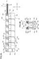
- the two adjacent first guide units 63, 63 are connected by inserting the left end parts of both of the side walls 63a, 63a of the other of the first guide units 63 into an inner side of the right end parts of one of the first guide units 63 in the opposite direction of both of the side walls 63a, 63a and by loosely fitting each of the pins 63c of the other of the first guide units 63 in each of the openings 63d of one of the first guide units 63.
- both of the pins 63c, 63c form a pivot.
- the first guide 6 is formed by repetition of such connection of the two adjacent first guide units 63, 63.
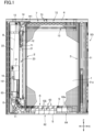
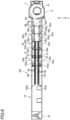
- each of the first guide units 63 is identical, and due to the pivotal movement in the above-mentioned pivotal movement range of each of the first guide units 63, the first guide 6, as shown in FIG. 1 , bends so as to direct toward the upper end portion of the first frame 2 when the first guide 6 is stored in the inside of the first frame 2, and the first guide 6 directs rightward and returns to a linear state when the first guide 6 is drawn from the inside the first frame 2.
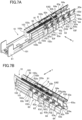
- each of the second recessed parts 63a 3 that are formed at both of the side walls 63a, 63a of one of the two adjacent first guide units 63, 63, which pivotally moves, is inserted into the inside in the opposite direction of both of the side walls 63a, 63a of the other first guide units 63. Therefore, outer side surfaces in the opposite direction of the lower parts of both of the side walls 63a, 63a of each of the first units 63 are disposed in a same plane in the drawn portion 62 of the first guide 6 from the inside of the first frame 2.
- the screen retaining member 9 can be detached from the first guide 6, while being guided by each of the rail parts 63g, by drawing the base 91 from the inside of each of the storage parts 63i of each of the first guide units 63 from one of the right and left ends of the first guide 6.
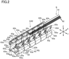
- the base 91 is locked by the locking part 63h 1 of the supporting piece 63h of each of the first guide units 63 and all of the needle-like parts 92 are inclined to a side of the bottom wall 63b along the downward slope of the inclined part 63h 2 by the inclined part 63h 2 . See FIG.3B . Due to the inclination of all of the needle-like parts 92, gaps in the Y-axis direction, which are shown in FIG. 2 , are formed between tip ends in a protruding direction of the needle-like parts 92 of two of the screen retaining members 9 attached to both of the side walls 63a, 63a of each of the first guide units 63 in the first guide 6.
- each of the first guide units 63 i.e., the bending of the first guide 6 is smoothly realized by disposition of the base 91 in parallel to the imaginary line VL. Additionally, since the above-mentioned pivot is positioned at the upper end part of the each of the first guide units 63, the above-mentioned pivot is disposed further upward from the lower end of the above-mentioned opening in which the screen apparatus SD is installed. Accordingly, the pivot is less susceptible to dust, sand, mud, and the like which are easily accumulated on the lower end of the above-mentioned opening, and coupled with the smooth bending of the first guide 6, a closing operation of the first frame 2 by the user is performed lightly and stably.
- the base 91 of the screen retaining member 9 easily returns to the linear state from a bent state, the return of the first guide 6 from the bent state to the linear state when the first guide 6 is drawn from the inside of the first frame 2 can also be smoothly realized. Accordingly, an opening operation of the first frame 2 is also performed lightly and stably.
- a concave part 63j that extends in the same direction as the portion 62 of the first guide 6, which is drawn from the inside of the first frame 2, extends and is recessed inward in the opposite direction of both of the side walls 63a, 63a is provided with both of the side walls 63a, 63a of each of the first guide units 63.
- a third recessed part 63a 4 that is recessed inward in the opposite direction of both of the side walls 63a, 63a and is similar to the first recessed part 63a 1 and the second recessed part 63a 3 is formed at the left end part of the both of the side walls 63a, 63a, at which the concave part 63j is provided.
- the second notched part 63as of the first guide unit 63 that pivotally moves overlaps on the third recessed part 63a 4 of the first guide unit 63 that has finished pivotal movement and is disposed adjacent to the first guide unit 63 that pivotally moves.
- Linearity of the portion 62 of the first guide 6, which is drawn from the inside of the first frame 2, is maintained by overlapping of the second notch 63as on the third recessed part 63a 4 and a contact between the right end of the lower end part of both of the side walls 63a, 63a of the first guide unit 63 that pivotally moves and the left end of both of the side walls 63a, 63a of the first guide unit 63 that has finished pivoting. Additionally, the inner surfaces in the opposite direction of both of the side walls 63a, 63a, at which the concave parts 63j are formed, respectively, are placed flush with each other.
- each of the third notched parts 63a 6 causes the engagement of the each of the guided pieces 63k with one side end portion and the other side end portion in the Y-axis direction of the lower rail 5 to smoothly release, and separation of the each of the first guide units 63 from the lower rail 5 is facilitated.
- the sliding in the left-right direction of the first frame 2 is realized more smoothly.
- a right end of the first guide 6 is fixed to the lower end portion of the second frame 3 and becomes a fixed end. Additionally, the free end 61 of the first guide 6 is always stored in the inside of the first frame 2. Specifically, the free end 61 is positioned at an upper end of an adjuster 10 that moves up and down in the top-bottom direction in the inside of the first frame 2. The adjuster 10 is connected to the first guide unit 63 positioned at an upper end when the first guide 6 is stored in the inside of the first guide 6. A weight 101 that is longitudinal in the top-bottom direction and lumpy is attached to the adjuster 10. Gravitational force acting on the weight 101 acts on the portion of the first guide 6, which is stored in the inside of the first frame 2.
- the gravitational force assists the first guide 6 to be smoothly drawn rightward from the inside of the first frame 2 against the elastic force of the coil spring 31a built in the roller pipe 31 and provides the closing operation by the user a comfortable and stable feeling.
- the gravitational force acting on the weight 101 provides a suitable resistance to the storage of the first guide 6 in the inside of the first frame 2. Rapid winding of the screen 1 around the outer periphery of the roller pipe 31 due to release of the elastic force accumulated in the coil spring 31a is suppressed by the resistance.
- a stored length in the first storage portion 22 and a drawn length of the first storage portion 22 of the first guide 6 become equal to a stored length in the second storage portion 23 and a drawn length of the second storage portion 23 of the second guide 7 due to the loop formed by the tension member 8.
- a parallel sliding of the first frame 2 with respect to the second frame 3 can be certainly realized.
- the parallel sliding of the first frame 2 is realized by the closing operation of the user at an arbitrary portion in the top-bottom direction of the first frame 2. Further, the parallel sliding of the first frame 2 is also realized during the opening operation due to the elastic force of the coil spring 31a.
- the prescribed tension applied to the tension member 8 is appropriately set under consideration of the above-mentioned sliding of the first frame 2.
- an automatic opening and closing manner using a torque when a motor rotates for the expansion and storage of the screen 1 and an opening and closing manner manually performing both of the expansion and storage of the screen 1 may be applicable to the screen apparatus SD.
- a foldable screen in which a plurality of pleats are formed can be adopted to the screen 1.
Landscapes
- Engineering & Computer Science (AREA)
- Structural Engineering (AREA)
- Architecture (AREA)
- Civil Engineering (AREA)
- Life Sciences & Earth Sciences (AREA)
- Insects & Arthropods (AREA)
- Pest Control & Pesticides (AREA)
- Operating, Guiding And Securing Of Roll- Type Closing Members (AREA)
Applications Claiming Priority (1)
| Application Number | Priority Date | Filing Date | Title |
|---|---|---|---|
| PCT/JP2021/019999 WO2022249334A1 (ja) | 2021-05-26 | 2021-05-26 | スクリーン装置 |
Publications (3)
| Publication Number | Publication Date |
|---|---|
| EP4350118A1 EP4350118A1 (en) | 2024-04-10 |
| EP4350118A4 EP4350118A4 (en) | 2024-10-16 |
| EP4350118B1 true EP4350118B1 (en) | 2025-07-09 |
Family
ID=84228581
Family Applications (1)
| Application Number | Title | Priority Date | Filing Date |
|---|---|---|---|
| EP21942988.3A Active EP4350118B1 (en) | 2021-05-26 | 2021-05-26 | Screen apparatus |
Country Status (8)
| Country | Link |
|---|---|
| US (1) | US20240218734A1 (pl) |
| EP (1) | EP4350118B1 (pl) |
| JP (1) | JP7664383B2 (pl) |
| CN (1) | CN117355659A (pl) |
| ES (1) | ES3044660T3 (pl) |
| PL (1) | PL4350118T3 (pl) |
| PT (1) | PT4350118T (pl) |
| WO (1) | WO2022249334A1 (pl) |
Families Citing this family (1)
| Publication number | Priority date | Publication date | Assignee | Title |
|---|---|---|---|---|
| PT4350115T (pt) * | 2021-06-02 | 2025-10-10 | Metaco Inc | Estrutura de cablagem para membro de tração em dispositivo de malha |
Family Cites Families (39)
| Publication number | Priority date | Publication date | Assignee | Title |
|---|---|---|---|---|
| US4467853A (en) * | 1982-08-20 | 1984-08-28 | Harsco Corporation | Door with guide insulation and weatherstripping |
| JPH09279967A (ja) * | 1996-04-11 | 1997-10-28 | Katsuaki Tomita | ロールスクリーン |
| US6186212B1 (en) * | 1998-06-11 | 2001-02-13 | Metaco Inc. | Screen device |
| US6082432A (en) * | 1998-07-22 | 2000-07-04 | Kissinger; Daren | Screen door accessory |
| US6629555B2 (en) * | 2001-10-25 | 2003-10-07 | Odl, Incorporated | Retractable screen door |
| GB0129189D0 (en) * | 2001-12-06 | 2002-01-23 | Reddiplex Group Plc | Sliding screen edge seals |
| JP4109573B2 (ja) * | 2003-05-21 | 2008-07-02 | セイキ販売株式会社 | 巻取り式スクリーン装置 |
| WO2005001230A1 (ja) * | 2003-06-30 | 2005-01-06 | Seiki Hanbai Co., Ltd. | スクリーン装置 |
| AU2004319870A1 (en) * | 2004-04-27 | 2005-12-01 | Tsuchiya Tsco Co., Ltd. | Weatherseals |
| JP4693366B2 (ja) * | 2004-06-14 | 2011-06-01 | 株式会社メタコ | スクリーン装置 |
| CA2581742C (en) * | 2004-10-07 | 2011-11-01 | Seiki Sogyo Co., Ltd. | Net guide for wire screen and wire screen apparatus having the same |
| JP4850498B2 (ja) * | 2005-11-30 | 2012-01-11 | セイキ販売株式会社 | 折畳式スクリーン装置 |
| JP4794373B2 (ja) * | 2006-06-23 | 2011-10-19 | 株式会社メタコ | スクリーン装置 |
| JP4954676B2 (ja) * | 2006-11-10 | 2012-06-20 | 株式会社メタコ | スクリーン装置 |
| US7810543B2 (en) * | 2007-12-11 | 2010-10-12 | Effe S.R.L. | Roller screen device |
| JP5358126B2 (ja) * | 2008-06-09 | 2013-12-04 | 株式会社メタコ | スクリーン装置 |
| JP5159503B2 (ja) * | 2008-08-06 | 2013-03-06 | 株式会社メタコ | スクリーン装置 |
| NZ584412A (en) * | 2009-04-02 | 2011-10-28 | Chris Bonython | Screen for a door or window that is wider than it is tall |
| JP5284238B2 (ja) * | 2009-10-07 | 2013-09-11 | 株式会社メタコ | スクリーン装置 |
| JP5284239B2 (ja) * | 2009-10-07 | 2013-09-11 | 株式会社メタコ | スクリーン装置 |
| ITTO20090181U1 (it) | 2009-12-04 | 2011-06-05 | Effe S R L | Elementi di guida di zanzariere mobili. |
| US8336286B2 (en) * | 2010-02-10 | 2012-12-25 | Prince Castle LLC | Push chain with a bias spring to prevent buckling |
| GR1007359B (el) | 2010-07-12 | 2011-07-27 | Αργυριος Διονυσιου Παπαδοπουλος | Συστημα συγκρατησης αντικουνουπικου πανιου εντος αρθρωτου οδηγου |
| NL2007194C2 (en) * | 2011-07-28 | 2013-01-29 | Unilux Nederland B V | Retractable and extendable covering device. |
| US20130306252A1 (en) * | 2012-05-16 | 2013-11-21 | Mckeon Rolling Steel Door Co., Inc. | Coiling door assembly having guide members with narrow wall gap opening and internal smoke or weather seal |
| ES2631141T3 (es) * | 2012-08-10 | 2017-08-28 | Mv Line S.P.A. | Dispositivo de control y movimiento para mosquiteras, cortinas y similares |
| JP2014081058A (ja) * | 2012-10-18 | 2014-05-08 | Tsubakimoto Chain Co | 押し引き両用チェーン、進退作動装置 |
| JP6000807B2 (ja) * | 2012-11-05 | 2016-10-05 | 株式会社メタコ | スクリーン装置のスライドガイド枠部 |
| JP6320863B2 (ja) * | 2014-07-15 | 2018-05-09 | 株式会社メタコ | スクリーン装置 |
| CN105987128B (zh) * | 2015-03-23 | 2019-11-22 | 清展科技股份有限公司 | 屏幕装置之链条结构及其链接单元件 |
| ITUB20151071A1 (it) | 2015-05-27 | 2016-11-27 | Langellotti Angelo | Sistema perfezionato di tenuta laterale per schermature avvolgibili come ad esempio zanzariere e tende a rete |
| JP6612162B2 (ja) * | 2016-03-24 | 2019-11-27 | セイキ販売株式会社 | スクリーン装置 |
| IT201700046539A1 (it) | 2017-04-28 | 2018-10-28 | Date System S R L | Zanzariera ad avvolgimento laterale per porte o finestre. |
| EP3517805B8 (de) * | 2018-01-29 | 2022-04-13 | Auto-Motion Shade Inc. | Kette für eine abschirmvorrichtung |
| JP7227719B2 (ja) | 2018-09-04 | 2023-02-22 | キヤノン株式会社 | 画像処理装置、撮像装置、画像処理方法、及びプログラム |
| IT201900009744A1 (it) | 2019-06-21 | 2020-12-21 | Biessebi S R L | Apparato di schermatura per schermare una apertura ricavata in una parete |
| US11505991B2 (en) * | 2021-03-24 | 2022-11-22 | Metaco Inc. | Screen device |
| PT4350117T (pt) * | 2021-05-26 | 2025-10-10 | Metaco Inc | Aparelho de malha |
| PT4350115T (pt) * | 2021-06-02 | 2025-10-10 | Metaco Inc | Estrutura de cablagem para membro de tração em dispositivo de malha |
-
2021
- 2021-05-26 JP JP2023523807A patent/JP7664383B2/ja active Active
- 2021-05-26 WO PCT/JP2021/019999 patent/WO2022249334A1/ja not_active Ceased
- 2021-05-26 US US18/289,150 patent/US20240218734A1/en active Pending
- 2021-05-26 EP EP21942988.3A patent/EP4350118B1/en active Active
- 2021-05-26 PT PT219429883T patent/PT4350118T/pt unknown
- 2021-05-26 CN CN202180098279.XA patent/CN117355659A/zh active Pending
- 2021-05-26 PL PL21942988.3T patent/PL4350118T3/pl unknown
- 2021-05-26 ES ES21942988T patent/ES3044660T3/es active Active
Also Published As
| Publication number | Publication date |
|---|---|
| EP4350118A1 (en) | 2024-04-10 |
| CN117355659A (zh) | 2024-01-05 |
| JPWO2022249334A1 (pl) | 2022-12-01 |
| WO2022249334A1 (ja) | 2022-12-01 |
| PT4350118T (pt) | 2025-10-09 |
| ES3044660T3 (en) | 2025-11-27 |
| EP4350118A4 (en) | 2024-10-16 |
| PL4350118T3 (pl) | 2025-11-24 |
| US20240218734A1 (en) | 2024-07-04 |
| JP7664383B2 (ja) | 2025-04-17 |
Similar Documents
| Publication | Publication Date | Title |
|---|---|---|
| EP0999335B1 (en) | Screen device | |
| EP2487317B1 (en) | Screen device | |
| JP4693366B2 (ja) | スクリーン装置 | |
| US6059007A (en) | Rolling screen | |
| US11505991B2 (en) | Screen device | |
| EP4350117B1 (en) | Screen apparatus | |
| NZ500356A (en) | Guidance device for a flexible curtain door | |
| EP4350118B1 (en) | Screen apparatus | |
| JP7343423B2 (ja) | スクリーン装置 | |
| JP5409083B2 (ja) | 横型ブラインドの高さ調節装置 | |
| EP4350115B1 (en) | Wiring structure for tension member in screen device | |
| IT201900002879A1 (it) | Dispositivo di tensionamento per zanzariere e tende avvolgibili | |
| EP4063605B1 (en) | Screen device | |
| AU2021203470A1 (en) | Screen device | |
| JPH0128236Y2 (pl) | ||
| JP2022049360A (ja) | ロールスクリーン装置 | |
| JPH0650639Y2 (ja) | 巻取式スクリーン装置 | |
| CN115104883A (zh) | 屏风装置 | |
| JP7651037B2 (ja) | 引手部材 | |
| JP4676076B2 (ja) | スクリーン装置 | |
| JP3819128B2 (ja) | 建物用シャッター | |
| JPH085276Y2 (ja) | ブラインド | |
| IT201600125198A1 (it) | Dispositivo di tensionamento per zanzariere e tende avvolgibili |
Legal Events
| Date | Code | Title | Description |
|---|---|---|---|
| STAA | Information on the status of an ep patent application or granted ep patent |
Free format text: STATUS: THE INTERNATIONAL PUBLICATION HAS BEEN MADE |
|
| PUAI | Public reference made under article 153(3) epc to a published international application that has entered the european phase |
Free format text: ORIGINAL CODE: 0009012 |
|
| STAA | Information on the status of an ep patent application or granted ep patent |
Free format text: STATUS: REQUEST FOR EXAMINATION WAS MADE |
|
| 17P | Request for examination filed |
Effective date: 20231106 |
|
| AK | Designated contracting states |
Kind code of ref document: A1 Designated state(s): AL AT BE BG CH CY CZ DE DK EE ES FI FR GB GR HR HU IE IS IT LI LT LU LV MC MK MT NL NO PL PT RO RS SE SI SK SM TR |
|
| DAV | Request for validation of the european patent (deleted) | ||
| DAX | Request for extension of the european patent (deleted) | ||
| A4 | Supplementary search report drawn up and despatched |
Effective date: 20240918 |
|
| RIC1 | Information provided on ipc code assigned before grant |
Ipc: E06B 9/58 20060101ALI20240912BHEP Ipc: E06B 9/54 20060101AFI20240912BHEP |
|
| GRAP | Despatch of communication of intention to grant a patent |
Free format text: ORIGINAL CODE: EPIDOSNIGR1 |
|
| STAA | Information on the status of an ep patent application or granted ep patent |
Free format text: STATUS: GRANT OF PATENT IS INTENDED |
|
| INTG | Intention to grant announced |
Effective date: 20250219 |
|
| GRAS | Grant fee paid |
Free format text: ORIGINAL CODE: EPIDOSNIGR3 |
|
| GRAA | (expected) grant |
Free format text: ORIGINAL CODE: 0009210 |
|
| STAA | Information on the status of an ep patent application or granted ep patent |
Free format text: STATUS: THE PATENT HAS BEEN GRANTED |
|
| P01 | Opt-out of the competence of the unified patent court (upc) registered |
Free format text: CASE NUMBER: APP_23793/2025 Effective date: 20250519 |
|
| AK | Designated contracting states |
Kind code of ref document: B1 Designated state(s): AL AT BE BG CH CY CZ DE DK EE ES FI FR GB GR HR HU IE IS IT LI LT LU LV MC MK MT NL NO PL PT RO RS SE SI SK SM TR |
|
| REG | Reference to a national code |
Ref country code: GB Ref legal event code: FG4D |
|
| REG | Reference to a national code |
Ref country code: CH Ref legal event code: EP |
|
| REG | Reference to a national code |
Ref country code: IE Ref legal event code: FG4D |
|
| REG | Reference to a national code |
Ref country code: DE Ref legal event code: R096 Ref document number: 602021034010 Country of ref document: DE |
|
| REG | Reference to a national code |
Ref country code: PT Ref legal event code: SC4A Ref document number: 4350118 Country of ref document: PT Date of ref document: 20251009 Kind code of ref document: T Free format text: AVAILABILITY OF NATIONAL TRANSLATION Effective date: 20251003 |
|
| REG | Reference to a national code |
Ref country code: NL Ref legal event code: FP |
|
| REG | Reference to a national code |
Ref country code: ES Ref legal event code: FG2A Ref document number: 3044660 Country of ref document: ES Kind code of ref document: T3 Effective date: 20251127 |