EP4344686B1 - Ophthalmisches laserbehandlungsgerät - Google Patents
Ophthalmisches laserbehandlungsgerät Download PDFInfo
- Publication number
- EP4344686B1 EP4344686B1 EP23200023.2A EP23200023A EP4344686B1 EP 4344686 B1 EP4344686 B1 EP 4344686B1 EP 23200023 A EP23200023 A EP 23200023A EP 4344686 B1 EP4344686 B1 EP 4344686B1
- Authority
- EP
- European Patent Office
- Prior art keywords
- irradiation
- treatment
- guide
- laser light
- spot
- Prior art date
- Legal status (The legal status is an assumption and is not a legal conclusion. Google has not performed a legal analysis and makes no representation as to the accuracy of the status listed.)
- Active
Links
Images












Classifications
-
- A—HUMAN NECESSITIES
- A61—MEDICAL OR VETERINARY SCIENCE; HYGIENE
- A61F—FILTERS IMPLANTABLE INTO BLOOD VESSELS; PROSTHESES; DEVICES PROVIDING PATENCY TO, OR PREVENTING COLLAPSING OF, TUBULAR STRUCTURES OF THE BODY, e.g. STENTS; ORTHOPAEDIC, NURSING OR CONTRACEPTIVE DEVICES; FOMENTATION; TREATMENT OR PROTECTION OF EYES OR EARS; BANDAGES, DRESSINGS OR ABSORBENT PADS; FIRST-AID KITS
- A61F9/00—Methods or devices for treatment of the eyes; Devices for putting in contact-lenses; Devices to correct squinting; Apparatus to guide the blind; Protective devices for the eyes, carried on the body or in the hand
- A61F9/007—Methods or devices for eye surgery
- A61F9/008—Methods or devices for eye surgery using laser
- A61F9/00821—Methods or devices for eye surgery using laser for coagulation
-
- A—HUMAN NECESSITIES
- A61—MEDICAL OR VETERINARY SCIENCE; HYGIENE
- A61F—FILTERS IMPLANTABLE INTO BLOOD VESSELS; PROSTHESES; DEVICES PROVIDING PATENCY TO, OR PREVENTING COLLAPSING OF, TUBULAR STRUCTURES OF THE BODY, e.g. STENTS; ORTHOPAEDIC, NURSING OR CONTRACEPTIVE DEVICES; FOMENTATION; TREATMENT OR PROTECTION OF EYES OR EARS; BANDAGES, DRESSINGS OR ABSORBENT PADS; FIRST-AID KITS
- A61F9/00—Methods or devices for treatment of the eyes; Devices for putting in contact-lenses; Devices to correct squinting; Apparatus to guide the blind; Protective devices for the eyes, carried on the body or in the hand
- A61F9/007—Methods or devices for eye surgery
- A61F9/008—Methods or devices for eye surgery using laser
- A61F9/00825—Methods or devices for eye surgery using laser for photodisruption
- A61F9/0084—Laser features or special beam parameters therefor
-
- A—HUMAN NECESSITIES
- A61—MEDICAL OR VETERINARY SCIENCE; HYGIENE
- A61F—FILTERS IMPLANTABLE INTO BLOOD VESSELS; PROSTHESES; DEVICES PROVIDING PATENCY TO, OR PREVENTING COLLAPSING OF, TUBULAR STRUCTURES OF THE BODY, e.g. STENTS; ORTHOPAEDIC, NURSING OR CONTRACEPTIVE DEVICES; FOMENTATION; TREATMENT OR PROTECTION OF EYES OR EARS; BANDAGES, DRESSINGS OR ABSORBENT PADS; FIRST-AID KITS
- A61F9/00—Methods or devices for treatment of the eyes; Devices for putting in contact-lenses; Devices to correct squinting; Apparatus to guide the blind; Protective devices for the eyes, carried on the body or in the hand
- A61F9/007—Methods or devices for eye surgery
- A61F9/008—Methods or devices for eye surgery using laser
- A61F9/00825—Methods or devices for eye surgery using laser for photodisruption
-
- A—HUMAN NECESSITIES
- A61—MEDICAL OR VETERINARY SCIENCE; HYGIENE
- A61F—FILTERS IMPLANTABLE INTO BLOOD VESSELS; PROSTHESES; DEVICES PROVIDING PATENCY TO, OR PREVENTING COLLAPSING OF, TUBULAR STRUCTURES OF THE BODY, e.g. STENTS; ORTHOPAEDIC, NURSING OR CONTRACEPTIVE DEVICES; FOMENTATION; TREATMENT OR PROTECTION OF EYES OR EARS; BANDAGES, DRESSINGS OR ABSORBENT PADS; FIRST-AID KITS
- A61F9/00—Methods or devices for treatment of the eyes; Devices for putting in contact-lenses; Devices to correct squinting; Apparatus to guide the blind; Protective devices for the eyes, carried on the body or in the hand
- A61F9/007—Methods or devices for eye surgery
- A61F9/008—Methods or devices for eye surgery using laser
- A61F2009/00844—Feedback systems
-
- A—HUMAN NECESSITIES
- A61—MEDICAL OR VETERINARY SCIENCE; HYGIENE
- A61F—FILTERS IMPLANTABLE INTO BLOOD VESSELS; PROSTHESES; DEVICES PROVIDING PATENCY TO, OR PREVENTING COLLAPSING OF, TUBULAR STRUCTURES OF THE BODY, e.g. STENTS; ORTHOPAEDIC, NURSING OR CONTRACEPTIVE DEVICES; FOMENTATION; TREATMENT OR PROTECTION OF EYES OR EARS; BANDAGES, DRESSINGS OR ABSORBENT PADS; FIRST-AID KITS
- A61F9/00—Methods or devices for treatment of the eyes; Devices for putting in contact-lenses; Devices to correct squinting; Apparatus to guide the blind; Protective devices for the eyes, carried on the body or in the hand
- A61F9/007—Methods or devices for eye surgery
- A61F9/008—Methods or devices for eye surgery using laser
- A61F2009/00861—Methods or devices for eye surgery using laser adapted for treatment at a particular location
- A61F2009/00868—Ciliary muscles or trabecular meshwork
-
- A—HUMAN NECESSITIES
- A61—MEDICAL OR VETERINARY SCIENCE; HYGIENE
- A61F—FILTERS IMPLANTABLE INTO BLOOD VESSELS; PROSTHESES; DEVICES PROVIDING PATENCY TO, OR PREVENTING COLLAPSING OF, TUBULAR STRUCTURES OF THE BODY, e.g. STENTS; ORTHOPAEDIC, NURSING OR CONTRACEPTIVE DEVICES; FOMENTATION; TREATMENT OR PROTECTION OF EYES OR EARS; BANDAGES, DRESSINGS OR ABSORBENT PADS; FIRST-AID KITS
- A61F9/00—Methods or devices for treatment of the eyes; Devices for putting in contact-lenses; Devices to correct squinting; Apparatus to guide the blind; Protective devices for the eyes, carried on the body or in the hand
- A61F9/007—Methods or devices for eye surgery
- A61F9/008—Methods or devices for eye surgery using laser
- A61F2009/00878—Planning
-
- A—HUMAN NECESSITIES
- A61—MEDICAL OR VETERINARY SCIENCE; HYGIENE
- A61F—FILTERS IMPLANTABLE INTO BLOOD VESSELS; PROSTHESES; DEVICES PROVIDING PATENCY TO, OR PREVENTING COLLAPSING OF, TUBULAR STRUCTURES OF THE BODY, e.g. STENTS; ORTHOPAEDIC, NURSING OR CONTRACEPTIVE DEVICES; FOMENTATION; TREATMENT OR PROTECTION OF EYES OR EARS; BANDAGES, DRESSINGS OR ABSORBENT PADS; FIRST-AID KITS
- A61F9/00—Methods or devices for treatment of the eyes; Devices for putting in contact-lenses; Devices to correct squinting; Apparatus to guide the blind; Protective devices for the eyes, carried on the body or in the hand
- A61F9/007—Methods or devices for eye surgery
- A61F9/008—Methods or devices for eye surgery using laser
- A61F2009/00885—Methods or devices for eye surgery using laser for treating a particular disease
- A61F2009/00891—Glaucoma
-
- A—HUMAN NECESSITIES
- A61—MEDICAL OR VETERINARY SCIENCE; HYGIENE
- A61F—FILTERS IMPLANTABLE INTO BLOOD VESSELS; PROSTHESES; DEVICES PROVIDING PATENCY TO, OR PREVENTING COLLAPSING OF, TUBULAR STRUCTURES OF THE BODY, e.g. STENTS; ORTHOPAEDIC, NURSING OR CONTRACEPTIVE DEVICES; FOMENTATION; TREATMENT OR PROTECTION OF EYES OR EARS; BANDAGES, DRESSINGS OR ABSORBENT PADS; FIRST-AID KITS
- A61F9/00—Methods or devices for treatment of the eyes; Devices for putting in contact-lenses; Devices to correct squinting; Apparatus to guide the blind; Protective devices for the eyes, carried on the body or in the hand
- A61F9/007—Methods or devices for eye surgery
- A61F9/008—Methods or devices for eye surgery using laser
- A61F2009/00897—Scanning mechanisms or algorithms
Definitions
- the present disclosure relates to an ophthalmic laser treatment device that treats tissue of a patient's eye by irradiating the tissue with treatment laser light.
- an ophthalmic laser treatment device disclosed in JP 2014-233469 A displays a target area to be irradiated with the treatment laser light on a display screen, and also displays an area that is actually irradiated with the treatment laser light (a post-irradiated area) when the treatment laser light is irradiated.
- the target irradiation area and the irradiated area are displayed for the purpose of allowing the operator to check the progress of the treatment.
- the ophthalmic laser therapeutic device disclosed in JP 2017-086154 is also considered relevant prior art knowledge.
- a typical objective of the present disclosure is to provide an ophthalmic laser treatment device that is configured to appropriately support treatment with a treatment laser light when a contact lens having a reflective surface is used.
- the ophthalmic laser treatment device in the present disclosure it is possible to appropriately support treatment with a treatment laser light when a contact lens having a reflective surface is used.
- An ophthalmic laser treatment device exemplified in the present disclosure irradiates the tissue of a patient's eye with treatment laser light each time an instruction for executing laser irradiation is input.
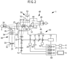
- the ophthalmic laser treatment device includes a laser irradiation optical system, an observation optical system, an internal display unit, and a control unit.
- the laser irradiation optical system irradiates a patient's eye with a treatment laser light.
- the observation optical system allows an operator to observe an observation image of the patient's eye through an eyepiece.
- the internal display unit is provided in the observation optical system and displays images to the operator via the eyepiece.
- the control unit manages various controls of the ophthalmic laser treatment device.
- the control unit executes an irradiation plan acquisition step and an aiming guide display step.
- the irradiation plan acquisition step when irradiating the patient's eye with the treatment laser beam using a contact lens having a reflective surface that reflects the treatment laser light in a direction intersecting the optical axis, the control unit acquires an irradiation plan in which the order of irradiation of treatment laser light is set for a plurality of irradiation spots to be irradiated.
- the control unit controls the internal display unit to display an aiming guide that assists the operator in adjusting the aiming point of the laser light adjusted by the operator to an appropriate position in accordance with progress of the irradiation plan.
- an aiming guide for assisting the operator in adjusting the aiming point is displayed on the internal display unit according to progress of the irradiation plan. Therefore, the operator checks the aiming guide while observing the patient's eye through the eyepiece (in other words, without taking his eyes off the eyepiece). Then, using the confirmed aiming guide as a reference, the aiming point for the treatment laser light can be adjusted. Therefore, the operator can more appropriately adjust the aiming point for the treatment laser light.
- the operator can easily adjust the aiming point more accurately even when it is difficult to confirm the treatment scar caused by the treatment laser light. It should be noted that the technology in this present disclosure is also very useful when treatment scars caused by treatment laser light can be observed.
- the optical axis of the treatment laser light irradiated by the laser irradiation optical system may be also aligned with the optical axis of the observation optical system.
- the control unit can display the image at an appropriate angle in an appropriate direction with the optical axis of the treatment laser light as a center.
- the laser irradiation optical system irradiates the patient's eye with aiming laser light (hereinafter, may be sometimes referred to as "aiming light") to make the operator aware of the planned irradiation position for the treatment laser light
- the optical axis of the aiming laser light may be also aligned with the optical axis of the observation optical system.
- the operator visually recognizes the aiming light at the center of the observation field and the display area of the internal display unit, it is easier to adjust the irradiation position of the treatment laser light based on the aiming light and the displayed content.
- the control unit may control the internal display unit to display a target location guide as the aiming guide on the internal display unit.
- the target location guide serves as a reference with which an arc-shaped or annular shaped treatment target location observed by the operator through the observation optical system is aligned.
- the operator can adjust the aiming point for the treatment laser light to an appropriate position by performing a various type of adjustments so as to cause the arc-shaped or annular-shaped treatment target location observed via the observation optical system to be aligned with the displayed target location guide.
- the target location guide may include a straight-line portion that is in parallel with a tangential direction that is in contact with an appropriate position of the next aiming spot in the arc-shaped or annular-shaped treatment target location when viewed from the line of sight of the operator in the observation optical system. Focusing on a part of the circumference (i.e., an area having an angular range of less than 180 degrees when viewed from the center of the circle), the slope of the tangent line is uniquely determined at a specific point on the circumference. The angular range of the arc-shaped or annular-shaped treatment target location observed through the reflective surface of the contact lens is less than 180 degrees.
- the aiming point for the treatment laser can be accurately adjusted.
- the curvature of the treatment target location to be observed is changed according to the size of the patient's eye, the magnification of the observation optical system (may be referred to as a "observation magnification"), etc.
- observation magnification the magnification of the observation optical system
- the control unit may change the curvature of the arc-shaped portion of the target location guide displayed on the internal display unit according to the magnification of the observation optical system. That is, the control unit may decrease the curvature of the arc-shaped portion of the target location guide as the magnification of the observation optical system increases. In this case, the arc-shaped portion of the target location guide changes appropriately in accordance with the difference in appearance of the treatment target location that changes depending on the observation magnification. Therefore, the aiming point can be adjusted more easily.
- the control unit may switch between displaying and non-displaying of at least a portion (for example, a straight portion or an arc-shaped portion) of the target location guide on the internal display unit in accordance with an instruction input by the operator.
- a portion for example, a straight portion or an arc-shaped portion
- the control unit may switch between displaying and non-displaying of at least a portion (for example, a straight portion or an arc-shaped portion) of the target location guide on the internal display unit in accordance with an instruction input by the operator.
- at least a portion of the target location guide is prevented from interfering with the treatment laser light.
- the target location guide includes a straight-line portion that is, when viewed in a direction along line of sight of the operator in the observation optical system, parallel to the appropriate direction of reflection of the treatment laser light to the next irradiation spot by the reflective surface of the contact lens.
- the operator adjusts the rotation angle of the reflective surface of the contact lens so that the arc-shaped or annular-shaped treatment target location approaches the straight-line portion of the target location guide in a perpendicular direction.
- the rotation angle of the reflective surface can be adjusted appropriately.
- the control unit determines the angle of the target location guide to be displayed on the internal display unit according to the progress of the irradiation plan, and then displays the target location guide at the determined angle. In this case, since the target location guide is displayed on the internal display unit at an appropriate angle according to the progress of the irradiation plan, the aiming point can be more appropriately adjusted.
- the control unit may determine the angle of the target location guide according to the position or direction of the irradiation spot that is in the first irradiation order determined by the irradiation plan.
- the control unit changes the angle of the displayed target location guide in accordance with the forward direction and the advancing angle of the irradiation spot. In this case, each time the laser irradiation is performed, the target location guide is displayed with an appropriate angle according to the next irradiation spot.
- a contact lens that has a reflective surface may be referred to as a "goniolens"
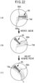
- the control unit may acquire information about the specified rotation angle (that is, the angle of rotation by one operation) of the used partially rotatable lens.
- the control unit may change the angle of the displayed target location guide in the forward direction of the irradiation spot at a specified angle each time a predetermined number of laser irradiations set to be performed within one specified rotation angle are completed.
- the target location guide is rotated to an angle corresponding to the next specified rotation angle range. Therefore, even when treatment is performed using a partially rotatable lens, the aim position can be adjusted more appropriately.
- the control unit may change the displaying manner of the target location guides based on information regarding the contact lenses being used. For example, if the contact lens being used is a contact lens that can be rotated as a whole by the operator, the control unit 60 may rotate the target location guide 71A by the advancing angle of the irradiation spot each time the laser irradiation is performed. In addition, when the contact lens being used is a partially rotatable lens, the control unit may rotate the target location guide by a specified rotation angle each time the laser irradiation is completed a predetermined number of times. In this case, since the display of the target location guides is appropriately changed according to the contact lens being used, the aiming position of the treatment laser light can be easily adjusted.
- the target location guide may be rotated by the specified rotation angle each time a predetermined number of laser irradiations are completed.
- the control unit may change the displaying method of the target location guide according to settings input by a user (for example, an operator).
- the control unit may display, on the internal display unit, an angle guide, as an aiming guide, indicative of a rotation angle of the reflective surface of the contact lens suitable for the progress of the irradiation plan.
- an angle guide as an aiming guide
- the operator refers to the angle indicated by the angle guide and adjusts the rotation angle of the reflective surface of the contact lens, thereby adjusting the aiming point of the treatment laser light while the angle of the reflective surface is being appropriately adjusted. Therefore, the aiming point of the treatment laser light can be adjusted more easily.
- the operator can easily adjust the rotation angle of the reflective surface of the contact lens by adjusting the angle of the treatment target location to be aligned with the angle guide.
- the angle guide with a shape that follows an appropriate reflection direction of the treatment laser light is displayed, the operator can easily adjust the rotation angle of the reflective surface of the contact lens by adjusting the reflection direction of the treatment laser light to follow the direction of the angle guide.
- the control unit may acquire information about the specified rotation angle (that is, the angle of rotation by one operation) of the used partially rotatable lens.
- the control unit may change the angle of the displayed angle guide in the forward direction of the irradiation spot at a specified angle each time a predetermined number of laser irradiations set to be performed within one specified rotation angle are completed. In this case, each time the laser irradiation within one specified rotation angle range is completed, the angle guide is rotated to an angle corresponding to the next specified rotation angle range. Therefore, even when treatment is performed using a partially rotatable lens, the aim position can be adjusted more appropriately.
- the control unit may change the displaying manner of the angle guides based on information regarding the contact lenses being used. For example, if the contact lens being used is a contact lens that can be rotated as a whole by the operator, the control unit may rotate the angle guide by the advancing angle of the irradiation spot each time the laser irradiation is performed. In addition, when the contact lens being used is a partially rotatable lens, the control unit may rotate the angle guide by a specified rotation angle each time the laser irradiation is completed a predetermined number of times. In this case, since the display of the angle guide is appropriately changed according to the contact lens being used, the aiming position of the treatment laser light can be easily adjusted.
- a spot arrangement guide map showing the arrangement of a plurality of consecutive irradiation spots including the next irradiation spot among the plurality of irradiation spots in the irradiation plan may be added to the angle guide.
- the control unit may shift the next irradiation spot to, among the plurality of irradiation spots included in the spot arrangement guide diagram, the irradiation spot adjacent in the forward direction determined by the irradiation plan each time the laser irradiation is performed. In this case, by grasping the position of the next irradiation spot displayed on the spot arrangement guide image, the operator can more appropriately adjust the next aiming point.
- an interval indicator schematic diagram it is more preferable to display a spot arrangement guide diagram such that the spot arrangement guide diagram is aligned with reference intervals indicated by the interval indicator schematic diagram.
- the operator can more appropriately adjust the next aiming point by grasping the positional relationship of the next irradiation spot shown in the spot arrangement guide image relative to the interval indicator schematic image.
- control unit may recommend rotation of the reflective surface using at least one of sound and vibration. Further, the control unit may recommend rotation of the reflective surface by controlling the internal display unit (for example, by rotating an image displayed on the internal display unit by a specified angle).
- the control unit may control the internal display unit to display, as the irradiation guide, an outer circumferential guide along a circumference of the observation field observed by the operator through the observation optical system.
- the outer circumferential guide may indicate at least one of a rotation angle of the reflective surface of the contact lens suitable for the progress of the irradiation plan or a direction to the irradiation spot to which the laser light should be applied.
- the operator can easily grasp at least one of the appropriate rotation angle of the reflective surface or the direction to the irradiation spot by visually recognizing the outer circumferential guide displayed along the outer circumference of the observation field.
- the outer circumferential guide may be displayed in an arc shape or an annular shape along the outer circumference of the observation field.
- the center of the arc or annular outer circumferential guide may be aligned with the optical axis of the observation optical system.
- the direction indicated by the outer circumferential guide coincides with the direction from the center of the observation field of view. Therefore, the operator can appropriately grasp the direction indicated by the outer circumferential guide.
- the outer circumferential guide may include a next aiming guide that indicates the direction to the next irradiation spot among the plurality of irradiation spots in the irradiation plan.
- the control unit may shift the position of the next aiming guide to a position corresponding to an irradiation spot that is determined in the irradiation plan and is located adjacent in a forward direction. In this case, the operator can appropriately grasp the direction to the next irradiation spot using the next aiming guide that is shifted along the outer circumference of the observation field.
- the outer circumferential guide may include an irradiation completion guide that indicates the direction to an irradiation spot, among a plurality of irradiation spots in the irradiation plan, that has already been irradiated with the treatment laser light.
- the control unit may change the displayed next aiming guide to the irradiation completion guide each time the laser irradiation is executed. In this case, the operator can appropriately adjust the next aiming point using the next aiming guide by grasping the direction in which the laser irradiation has been completed. It also becomes easier to recognize the progress of treatment.
- the outer circumferential guide may include a pre-irradiation guide that indicates the direction to an irradiation spot, among a plurality of irradiation spots in the irradiation plan, that is scheduled to be irradiated with treatment laser light later than the next time.
- the control unit replaces the pre-irradiation guide displayed in the direction of the irradiation spot in the next irradiation order determined in the irradiation plan with the next aiming guide.
- the operator can appropriately adjust the next aiming position using the next aiming guide by grasping the direction of the spot that is scheduled to be irradiated with the treatment laser light after the next time. It also becomes easier to recognize the progress of treatment.
- the outer circumferential guide may include a section aiming guide.
- the section aiming guide may indicate a direction to an irradiation section that is a section formed of a plurality of irradiation spots onto which the laser light is applied while the reflective surface of the contact lens is being fixed at a rotation angle.
- the section aiming guide may also indicate a direction to a rotation angle of the reflective surface that is suitable for irradiation with the laser light onto the irradiation section.
- the operator can easily grasp the direction to the plurality of irradiation sections or the direction to the reflective surface for irradiating the irradiation spots in the irradiation section with the treatment laser light using the section aiming guide. Therefore, it becomes easier to adjust the angle of the reflective surface of the contact lens.
- the control unit may display the section aiming guide for each range defined by a specified angle in the partially rotatable lens.
- the control unit may shift the position of the section aiming guide to an adjacent position in the forward direction determined by the irradiation plan each time the same number of laser irradiations as the number of the plurality of irradiation spots included within one specified angle range are completed.
- the section aiming guide is appropriately displayed in accordance with the specifications of the partially rotatable lens and the progress of treatment. Therefore, even when the partially rotatable lens is used, the section aiming guide appropriately assists in adjusting the aiming point.
- control unit may control the internal display unit to display an image of the treatment target location irradiated with aiming light.
- the treatment target location is captured by the imaging unit when the treatment laser light was emitted last time.
- the operator can adjust a next aiming point by grasping the location previously irradiated with the treatment laser light (that is, the region where the aiming light appears in the displayed image). Therefore, it becomes easier to irradiate the treatment laser light more appropriately.
- the ophthalmic laser treatment device may appropriately assist an operator in adjusting the aiming point even if the aiming guide is displayed by a display unit other than the internal display unit (for example, a display unit located outside of the observation optical system).
- the ophthalmic laser treatment device may also be defined as follows.
- An ophthalmic laser treatment device that irradiates a tissue of a patient's eye with a treatment laser light each time an instruction to perform irradiation with a treatment laser light is input, the ophthalmic laser treatment device including: a laser irradiation optical system that irradiates the patient's eye with the treatment laser light; an observation optical system that allows the operator to observe an observation image of the patient's eye through an eyepiece, a display unit that displays the image, and a control unit.
- the control unit is configured to perform an irradiation plan acquisition step and an aiming guide display step.
- the control unit acquires an irradiation plan defining an irradiation order in which the treatment laser light is applied to a plurality of irradiation spots that are scheduled to be irradiated by using a contact lens having a reflective surface that reflects the treatment laser light in a direction intersecting an optical axis.
- the control unit controls the display unit to display an aiming guide (at least one of an angle guide or an outer circumferential guide) in accordance with the progress of the irradiation plan. The aiming guide is displayed to assist the operator in adjusting the aiming spot for the treatment laser light to an apparatus position.
- the ophthalmic laser treatment device may execute only a process of recommending an operator to rotate the reflective surface of the partially rotatable lens, without executing a process of displaying the aiming guide.
- the ophthalmic laser treatment device may also be defined as follows.
- An ophthalmic laser treatment device that irradiates a tissue of a patient's eye with a treatment laser light each time an instruction to perform irradiation with the treatment laser light is input, the laser irradiation optical system including: a laser irradiation optical system that irradiates the patient's eye with a therapeutic laser beam; an observation optical system that allows an operator to observe an observation image of the patient's eye through an eyepiece; and a control unit.
- the control unit is configured to acquire an irradiation plan defining an irradiation order in which the treatment laser light is applied onto a plurality of irradiation spots that are scheduled to be irradiated with the treatment laser light using the partially rotatable lens.
- the control unit is configured to recommend the operator to rotate the reflective surface of the contact lens by a specified angle each time laser irradiation onto a specified angle area a specified number of times is completed.
- the ophthalmic laser treatment device reflects treatment laser light on the reflective surface of the contact lens, and irradiates an annular-shaped or arc-shaped treatment target location of a patient's eye with the treatment laser light.
- the ophthalmic laser treatment device includes a laser irradiation optical system and a superimposing display unit.
- the laser irradiation optical system emits the treatment laser light.
- the superimposing display unit superimposes a circumferential chart indicating angles in a circumferential direction with the optical axis of the treatment laser light as a center on an observation image including at least a portion of the treatment target location. In this case, by visually recognizing the circumferential direction chart superimposed on the observation image, the operator can appropriately grasp the direction of the treatment target location with respect to the optical axis of the treatment laser light.
- the contact lens may be temporarily removed from the patient's eye during treatment on multiple spots.
- the operator should circle the treatment target location in the direction in which the spot irradiated with the treatment laser light immediately before removing the contact lens (the angle in the circumferential direction centered on the optical axis of the treatment laser light) is located. It can be properly understood by referring to the circumferential chart. Therefore, when reattaching a contact lens that has been removed to the patient's eye, the contact lens should be adjusted while referring to the circumferential chart so that the aiming point of the treatment laser light can be adjusted appropriately in the direction where the next spot will be located. The angle can be adjusted. Therefore, the operator can easily and appropriately adjust the aiming point of the treatment laser light.
- the circumferential chart may include a plurality of indicators arranged at equal angles in a circumferential direction with the optical axis of the treatment laser light as a center.
- the plurality of indicators arranged at equal angles makes it easier for an operator to recognize the direction to the treatment target location more appropriately.
- the superimposing display unit may fixedly display the circumferential chart at a predetermined position within the image display area.
- the circumferential chart is fixedly displayed at a predetermined position regardless of the state of the observation image, and thus the direction to the treatment target location with the optical axis of the treatment laser light as a center can be recognized more accurately.
- the relative positional relationship between the optical axis of the optical system for making the operator visually recognize the observation image (for example, the observation optical system described later or the optical system of the observation imaging unit) and the optical axis of the treatment laser light may be fixed.
- the optical axis of the observation optical system and the optical axis O of the treatment laser light may always coincide with each other.
- the ophthalmic laser treatment device may include an observation optical system that causes the operator to observe an observation image including at least a portion of the treatment target location through an eyepiece.
- the superimposing display unit may be an internal display unit that displays images to an operator through an eyepiece.
- the ophthalmic laser treatment device may include an observation and imaging unit that captures an observation image of the patient's eye.
- the superimposing display unit (for example, a monitor) may superimpose a circumferential chart on the observation image captured by the observation and imaging unit.
- the configuration of the superimposing display unit may be a simple configuration in which it is impossible to change the image displayed superimposed on the observation image.
- the superimposing display unit may be configured to switch between superimposed display mode and non-display mode.
- the circumferential chart is not displayed so that the operator can concentrate on observing the observation image.
- the control unit may determine whether the circumferential chart is to be displayed based on whether a treatment mode set by the operator is an annular treatment mode where treatment on an annular-shaped or arc-shaped treatment target location is performed. In this case, a field of view in accordance to the set treatment mode is appropriately provided to the operator.
- the control unit executes an irradiation plan acquisition step and a spot interval guide display step.
- the control unit acquires an irradiation plan for irradiating a patient's eye with treatment laser light using a contact lens having a reflective surface that reflects the treatment laser light in a direction intersecting the optical axis.
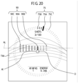
- the control unit controls the internal display unit to display a spot interval guide indicating appropriate intervals between a plurality of irradiation spots on which irradiation with treatment laser light is scheduled to be performed in accordance with the progress of the irradiation plan.
- the spot interval guide indicating appropriate intervals between a plurality of irradiation spots is displayed on the internal display unit according to the progress of the irradiation plan. Therefore, the operator checks the spot interval guide while observing the patient's eye through the eyepiece (that is, without taking his eyes off the eyepiece), and adjusts the plurality of aiming points for the treatment laser light using the confirmed spot interval guide as a reference. Therefore, the operator can easily cause the interval between the irradiation spots, to which treatment laser light is applied, to be an appropriate interval.
- the spot interval guide can also be treated as one example of the aiming guide that assists the operator in adjusting the aiming point for the treatment laser light to an appropriate position.
- a treatment method that allows observation of treatment scars caused by treatment laser light the operator can confirm the position of the treatment scars formed by previous laser irradiation, and then can adjust the aiming point of the treatment laser light for subsequent processes.
- a treatment method by which it is difficult to confirm the treatment scar caused by the treatment laser light for example, a treatment method performed with a lower power of the treatment laser light than the power with which the treatment scars was formed
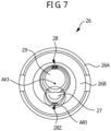
- a part of the contact lens (for example, an inner wall, etc.) has a plurality of interval indicators (may be referred to as "indexes") placed at regular intervals to serve as a reference for the interval between spots to which irradiation with treatment laser light is performed.
- the control unit may cause the intervals of at least some of the plurality of indicators included in the spot interval guide to coincide with the intervals of the interval indicators of the contact lens.
- the operator adjusts the aiming points while referring to the position and the direction of the interval indicators observed through the observation optical system and the position and the direction of the spot interval guide displayed on the internal display.
- the operator can appropriately adjust the aiming points for the treatment laser light.
- the control unit may cause the intervals of at least some of the plurality of indicators included in the spot interval guide to coincide with appropriate intervals of the plurality of irradiation spots.
- the operator can easily cause the intervals of the irradiation spot for the treatment laser light to be appropriate intervals by aligning movement distance from the former aiming spot to the next aiming spot with the interval of the indicators included in the spot interval guide 90. Therefore, it becomes easier to perform treatment in accordance with the treatment plan more appropriately.
- the spot interval guide may include a shape extending along an appropriate direction of reflection of the treatment laser light to the next irradiation spot by the reflective surface of the contact lens.
- the control unit may determine the angle of the spot interval guide to be displayed on the internal display unit according to the progress of the irradiation plan, and displays the spot interval guide at the determined angle. In this case, the operator can easily adjust the rotation angle of the reflective surface of the contact lens by adjusting the reflection angle of the treatment laser light to follow the direction indicated by the spot interval guide. Furthermore, since the spot interval guide is displayed on the internal display unit at an appropriate angle according to the progress of the irradiation plan, the aiming point can be more appropriately adjusted.
- the operator can easily adjust the rotation angle of the reflective surface of the contact lens by adjusting the rotation angle so that the interval indicator is located ahead of the direction indicated by the shape of the spot interval guide.
- the control unit may display the spot interval guide at a position spaced apart from the aiming point of the treatment laser light in the display area of the internal display unit.
- the control unit may display ends of the plurality of indicators included in the spot interval guide that are close to the aiming point for the treatment laser light along a curve line that extends approximately along the curve of the arc-shaped treatment location of the patient's eye.
- the spot interval guide is displayed at a position different from the aiming point for the treatment laser light (that is, the spot interval guide does not overlap with the aiming point).
- the operator can set the irradiation position of the treatment laser light by appropriately recognizing the state of the tissue at the aiming point.
- the spot interval guide when the spot interval guide is placed at an appropriate position relative to the next aiming point, the distance between the aim point side end of each of the plurality of indicators and the arc-shaped treatment location decreases.
- the operator can more appropriately adjust the next aiming point of the treatment laser light.
- the aiming point side end of each of the plurality of indicators may be displayed along a predetermined curve that is determined based on the average shape of the treatment area.
- the control unit may display a next aiming indicator for aligning the position of the next irradiation spot in the spot interval guide with a position corresponding to the optical axis of the treatment laser light emitted by the laser irradiation optical system.
- the control unit may shift the position of the next aiming index in the spot interval guide by one appropriate interval between the plurality of irradiation spots in the forward direction determined by the irradiation plan. In this case, the operator sets the position on the tissue to which the next treatment lase light is applied while considering the position of the next irradiation indicator on the optical axis of the treatment laser light (if the aiming light is emitted, the optical axis of the aiming light).
- the indicators other than the next aiming indicator 90A are post-irradiated indicators corresponding to the spots to which the treatment laser light has been applied or pre-irradiated indicators corresponding to the spots to which the treatment laser light has not been applied.
- the control unit may display each of the next aiming indicator, the post-irradiated indicator, and the pre-irradiated indicator in a different manner (that is, in a manner that makes each of these indicators distinguishable for the operator). In this case, the operator can easily grasp the positional relationship between the next aiming indicator, the post-irradiated indicator, and the pre-irradiated indicator, making it easier to proceed with the treatment more smoothly.
- the control unit may shift the spot interval guide by one appropriate interval between the plurality of irradiation spots in a direction opposite to the forward direction determined by the irradiation plan.
- the operator adjusts the aiming point every time so that the position of the plurality of indicators that are shifted each time the treatment laser light is emitted is fixed on the observation image observed through the observation optical system.
- the aiming point can be adjusted more easily.
- the contact lens is provided with an interval indicator
- the operator can easily adjust each of the plurality of aiming spots by appropriately adjusting a positional relationship between the interval indicators in the observation image and the plurality of indicators of the spot interval guide that is shifted each time laser light irradiation is performed. Even if an interval indicator is not formed in the contact lens, the operator can appropriately adjust each of the plurality of aiming points by appropriately adjusting the positional relationship between the characteristic parts present in the tissue included in the observation image and the plurality of indicators of the spot interval guide.
- the operator identifies one characteristic region on the observation image, and each time the spot interval guide is shifted by one appropriate interval of the irradiation spot (that is, each time the laser irradiation is performed), at least one of a shifting instruction to the device or rotation operation of the contact lens may be performed such that a specific indicator among the indicators (for example, the most left side indicator or the second left side indicator) is aligned with the specified characteristic location.
- a specific indicator among the indicators for example, the most left side indicator or the second left side indicator
- each of the multiple aim positions can be adjusted appropriately by matching at least one of the multiple indicators (i.e., the specific indicator mentioned above) to the characteristic location.
- the operator may perform at least one of a method of moving the relative position of the device with respect to the patient's eye or a method of rotating the contact lens.
- the control unit may display at least one of the plurality of indicators included in the spot interval guide by arranging the indicators along a straight-line. For example, the control unit may display the centers of gravity of the plurality of indicators included in the spot interval guide by arranging the centers along a straight-line. Further, the control unit may display ends of the plurality of indicators included in the spot interval guide that are away from the aiming point for the treatment laser light by arranging the ends along a straight-line. The control unit may move the spot interval guide along a linear direction in which at least some of the plurality of indicators are arranged each time irradiation with the treatment laser light is performed.
- the operator can proceed with the treatment more appropriately by matching the direction in which the plurality of index elements are arranged with the movement direction in which the aiming point of the treatment laser light is moved to the next aiming point.
- the reflective surface of a contact lens may include an edge or the like perpendicular to a direction extending outward from the central axis of the lens.
- the operator aligns the direction of the edge of the contact lens reflected in the observation image with the linear direction in which multiple index elements are arranged, and aims the treatment laser light along the direction of the edge. It is also possible to move it.
- the control unit may shift the spot interval guide by one appropriate interval between the plurality of irradiation spots in the forward direction determined by the irradiation plan or a direction opposite to the forward direction. For example, if a non-irradiation area where irradiation with the treatment laser light should not be performed, the operator inputs the skip instruction to skip the irradiation with the treatment laser light for the non-irradiation area. Thus, the operator restarts treatment from the irradiation spot that is planned to be irradiated next. Therefore, it becomes easier for the treatment to proceed more smoothly.
- the control unit may rotate the entire spot interval guide in the forward direction by the angle of one irradiation section (i.e., R/S degrees) each time laser light irradiation onto all the plurality of irradiation spots in the irradiation section under treatment is completed.
- each irradiation section has an angular range in which treatment laser light irradiated can be performed a prescribed number of times (multiple times) based on the spot interval guide while the angle of the spot interval guide is fixed.
- control unit may execute only a process of rotating the entire spot interval guide by the angle of the single irradiation section without executing a process of shifting the spot interval guide by the appropriate interval when executing the laser light irradiation.
- rotation adjustment pattern a pattern where the operator mainly executes a rotational operation of the contact lens when adjusting the aiming point for each of the plurality of irradiation spots included in one irradiation section.
- the control unit may shift the spot interval guide in a direction opposite to the forward direction determined by the irradiation plan by one appropriate interval between the plurality of irradiation spots each time laser light irradiation is performed. Furthermore, the control unit may rotate the contact lens by a rotation angle (hereinafter, may be referred to as a "unit angle") required to shift the aiming spot for the laser light to the next irradiation spot in the forward direction each time laser light irradiation is performed.
- a rotation angle hereinafter, may be referred to as a "unit angle”
- irradiation with the laser light multiple times in the single irradiation section is appropriately performed according to the progress of the irradiation plan by adjusting the aiming point by rotating the contact lens.
- the control unit may adjust the angle of the entire spot interval guide to the angle corresponding to the next irradiation section (i.e., for the next irradiation section) by rotating the entire spot interval guide in the forward direction each time laser light irradiation onto all the plurality of irradiation spots within the irradiation section under treatment is completed.
- irradiation with the treatment laser light onto each of the plurality of irradiation sections is automatically and appropriately assisted according to the progress of the irradiation plan.
- the control unit may execute only a process of rotating the spot interval guide by the unit angle each time laser light irradiation is executed without executing a process of shifting the spot interval guide by the appropriate interval between the plurality of irradiation spots. Even in this case, the operator can easily adjust the aiming spot to the next irradiation spot by rotating the contact lens.
- the rotation angle (i.e., the unit angle) of the contact lens required to move the aiming point for the treatment laser light to the next irradiation spot may change depending on various conditions.
- a virtual approximate circle that is, a circle through which a plurality of planned irradiation spots passes
- the unit angle T in the rotation adjustment pattern may be set, within a range smaller than R/N degrees, in accordance with the turning radius of the laser light when viewed in the visual axis direction of the patient's eye (i.e., a distance between the reflective position in the reflective surface of the contact lens and the position at which the laser light is applied.
- the control unit may rotate the spot interval guide by (R/S-T*(M-1)) degrees. In this case, the entire angle of the spot interval guide is adjusted appropriately to the angle corresponding to the next irradiation section.
- control unit may only rotate the aiming spot for the laser light by the rotation angle of the contact lens required to shift the aiming point to the next irradiation spot (i.e., the above-described unit angle T) without shifting the spot interval guide by the appropriate interval between the plurality of spot interval guide each time the laser light irradiation is performed.
- control unit may rotate the aiming spot for the laser light by the rotation angle (the above-described unit angle) required to shift the aiming point to the next irradiation spot without shifting the spot interval guide by the appropriate interval each time the laser light irradiation is performed.
- the control unit may adjust the angle of the entire spot interval guide to the angle corresponding to the next irradiation section (i.e., for the next irradiation section) by rotating the entire spot interval guide in the forward direction each time laser light irradiation onto all the plurality of irradiation spots within the irradiation section under treatment is completed.
- irradiation with the treatment laser light onto each of the plurality of irradiation sections is automatically and appropriately assisted according to the progress of the irradiation plan.
- the control unit may shift the spot interval guide in the forward direction determined in the irradiation plan or in a direction opposite to the forward direction by the appropriate interval between the plurality of irradiation spots Furthermore, when the skip instruction is input, the control unit may rotate the spot interval guide in the forward direction by the rotation angle of the contact lens required to shift the aiming spot to the next irradiation spot. In this case, the operator can skip irradiation with the treatment laser light to the non-irradiated area.
- the control unit may rotate the spot interval guide by the unit angle T without performing laser irradiation.
- the entire spot interval guide may be rotated by an angle corresponding to the range where the treatment has been done within the irradiation section being treated. In this case, even if the treatment for the irradiation section is not completely completed, the operator can move forward to treatment for the next irradiation section by rotating the entire spot interval guide. Therefore, it becomes easier for the treatment to proceed more smoothly.
- the method for calculating the angle when rotating the spot interval guide to the next irradiation section can be selected as appropriate.
- the angle between two adjacent irradiation spots is A degrees when viewed from the center of a circle through which multiple planned irradiation spots pass, and the number of the irradiation spots for which treatment has been done within the irradiation section under treatment is m.
- the angle corresponding to the range in which the treatment has been done within the irradiation section being treated may be calculated by "A (degrees) x m (number)".
- the number of irradiation spots "m" for which treatment has been done may also include the number of irradiation spots for which irradiation with the treatment laser light was skipped in accordance with the above-described skip instruction.
- the control unit may set an end of the indicators in a direction opposite to the forward direction of treatment to the position of the next irradiation indicator each time the plurality of indicators are rotated to the next irradiation section.
- the position of the next aiming indicator is appropriately changed according to the progress of the irradiation plan, making it easier for the treatment to proceed more smoothly.
- control unit may set all the indicators except the next irradiation indicator as the pre-irradiated indicators each time the plurality of indicators are rotated to the next irradiation section.
- the arc-shaped or annular-shaped treatment target location in the example shown in FIG. 10 , the trabecular meshwork TM
- the spot Al of the aiming light irradiated on the treatment target location are observed by the operator.
- the observation images of the treatment target location and the aiming light are a reflected image reflected by the reflective surface of the contact lens.
- FIG. 10 illustrates a situation where a contact lens that is not provided with the above-mentioned interval indicators 28 (see FIG. 7 ) and is not a partially rotatable lens is used.
- the center of the display area in the internal display unit 50, the observation optical axis of the observation optical system 40, the optical axis of the treatment laser light, and the optical axis of the aiming light are all aligned with each other at the center O. Therefore, the internal display unit 50 can display an image at an appropriate angle in an appropriate direction centered on the optical axis of the treatment laser light and the aiming light. In other words, the operator visually recognizes the aiming light at the center of the observation visual field and the center of the display area of the internal display unit 50. Therefore, it becomes easier to adjust the aiming light and the irradiation position of the treatment laser light based on the displayed images on the internal display unit 50.
- the treatment laser light is applied to the same spot as the aiming light spot Al.
- the ophthalmic laser treatment device 1 of the first embodiment displays a target location guide 71A on the internal display unit 50 as an aiming guide.
- the target location guide 71A is aligned with the arc-shaped or annular-shaped treatment target location (the trabecular meshwork TM in the example shown in FIG. 10 ) of the patient's eye E, which is observed by the operator via the observation optical system 40.
- the operator can adjust the irradiation position of the treatment laser light to an appropriate position by performing a various types of adjustments so as to cause the arc-shaped or annular-shaped treatment target location observed via the observation optical system 40 to be aligned with the displayed target location guide 71A.
- the target location guide 71A illustrated in FIG. 10 includes a line in parallel with the tangential direction that is in contact with the appropriate position of the irradiation spot that is determined by the irradiation plan as a next spot when viewed in a sight direction of the operator in the observation optical system. Due to the characteristics of a circle, there are two points on the circumference where straight-lines with a same particular inclination touch the circle, and these two points are located exactly opposite to each other with respect to the center of the circle.
- the operator operates at least one of the joystick 5 and the contact lens 26 to move the treatment target location so that the tangential direction of the arc-shaped or annular-shaped treatment target location is aligned with the direction of the straight-line portion of the target location guide 71A. Accordingly, the aiming point of the treatment laser light can be accurately adjusted.
- FIG. 10 shows a state in which the aiming point (the position of the aiming light spot Al) is accurately adjusted to the appropriate position of the next irradiation spot.
- the curvature of the treatment target location to be observed is changed according to the size of the patient's eye E, the observation magnification of the observation optical system 40, etc. This is because the observation range changes, and the treatment target site observed at the end of the observation range is affected by the curvature change.
- the target location guide 71A When adjustment is made to cause the target location guide 71A to be aligned with the tangential direction of the treatment target location, the treatment target location will be observed near the center of the observation range, which is the position of the aiming light.
- the operator can align the tangential direction of the treatment target location with the direction of the straight-line portion of the target location guide 71A, regardless of the size of the patient's eye E, observation magnification, etc. Therefore, the operator can more easily adjust the aiming point to an appropriate position.
- the target location guide 71A illustrated in FIG. 10 includes two straight-lines in parallel with the tangential direction as described above.
- the positions of the optical axis of the treatment laser light and the optical axis of the aiming light are located between the two straight-lines.
- the center of the aiming light spot Al observed by the operator is located between the two straight-lines in the target location guide 71A. Therefore, the operator can align the tangential direction of the treatment target location with the direction of the straight-line portion of the target location guide 71A, and at the same time aligns the aiming point of the treatment laser light (i.e., the spot Al of the aiming light) with the appropriate position of the treatment target location.
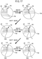
- the ophthalmic laser treatment device 1 of the first embodiment displays an outer circumferential guide 75 as an aiming guide on the internal display unit 50.
- the outer circumferential guide 75 indicates at least one of the rotation angle of the reflective surface of the contact lens suitable for the progress of the irradiation plan (that is, the direction in which the reflective surface 27 is disposed relative to the central axis AX1 of the contact lens 26) and the direction in which the irradiation spot to which the treatment laser light is to be emitted is located (i.e., the direction in which the irradiation spot in the observation image using the contact lens 26).
- the outer circumferential guide 75 is displayed along the outer circumference of the observation field of view by the operator via the observation optical system 40.
- the observation optical axis of the observation optical system 40 and the center of the display area of the internal display unit 50 are aligned with each other. Therefore, by displaying the outer circumferential guide 75 along the outer circumference of the observation field with the center of the display area of the internal display unit 50 as a reference, the operator can easily grasp the appropriate direction.
- the plurality of outer circumferential guides 75 are arranged in an arc-shape or an annular-shape along the outer circumference of the observation field. Further, when moving one of the outer circumferential guides 75, the control unit 60 moves it on an arc-shape or annular-shape line along the outer circumference of the observation field.
- the center of the arc-shape or annular-shape line on which the outer circumferential guide 75 is displayed is aligned with the observation optical axis of the observation optical system 40. Therefore, the operator can appropriately grasp the direction indicated by the outer circumferential guide 75.
- the outer circumferential guide 75 includes a next aiming guide 75A.
- the next aiming guide 75A indicates the appropriate direction of the next irradiation spot to be irradiated with the treatment laser light among the plurality of irradiation spots determined in the irradiation plan.
- the control unit 60 shifts the position of the next aiming guide 75A to a position corresponding to an irradiation spot that is determined in the irradiation plan and is located adjacent in a forward direction.
- next aiming guide 75A may be shifted by 3.6 degrees relative to the center O. Therefore, the operator can appropriately grasp the direction of the irradiation spot whose aiming point is to be adjusted next using the next aiming guide that is shifted along the outer circumference of the observation field.
- the outer circumferential guide 75 includes an completed irradiation guide 75B.
- the completed irradiation guide 75B indicates the direction of the irradiation spot that has already been irradiated with the treatment laser light, among the plurality of irradiation spots determined in the irradiation plan.
- the control unit 60 replaces the next aiming guide 75A, which was displayed just before the irradiation, with the completed irradiation guide 75B. Therefore, the operator can appropriately adjust the next aiming point using the next aiming guide 75A by grasping the direction in which the laser irradiation has been completed. It also becomes easier to recognize the progress of treatment.
- the outer circumferential guide 75 includes a pre-irradiation guide 75C.
- the pre-irradiation guide 75C indicates the direction of an irradiation spot that is scheduled to be irradiated with the treatment laser light subsequent to the next time, among the plurality of irradiation spots defined in the irradiation plan.
- the control unit 60 replaces the pre-irradiation guide 75C displayed in the direction of the irradiation spot in the next irradiation order determined in the irradiation plan with the next aiming guide 75A. Therefore, transition of the next irradiation guide 75A is performed.
- the operator can appropriately adjust the next aiming point using the next aiming guide 75A by grasping the direction of the irradiation spot that is scheduled to be irradiated with the treatment laser light after the next time. It also becomes easier to recognize the progress of treatment.
- control unit 60 displays each of the next aiming guide 75A, the completed irradiation guide 75B, and the pre-irradiation guide 75C in a distinguishable manner (that is, in a different displaying manner). Therefore, the operator can easily recognize the type of the outer circumferential guide 75 being displayed.
- control unit 60 may selectively display one or two of the next aiming guide 75A, the completed irradiation guide 75B, and the pre-irradiation guide 75C. In this case, it is desirable to display at least the next aiming guide 75A. Furthermore, it is more desirable to display both the next aiming guide 75A and the completed irradiation guide 75B.
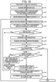
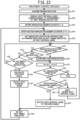
- the control unit 60 obtains an irradiation plan on treatment laser light for the patient's eye E (S1). As described above, in the irradiation plan, when the patient's eye E is irradiated with the treatment laser light using the contact lens 26 having the reflective surface 27, the irradiation order etc. for multiple irradiation spots scheduled to be irradiated with the treatment laser light are determined.
- the irradiation range of the treatment laser light (that is, the range in a circumferential direction in which a plurality of irradiation spots are arranged) in the annular treatment target location (the trabecular meshwork TM in this embodiment), the irradiation spot to be irradiated first, the number of irradiation spots, and the order of irradiation (including the irradiation direction) of the treatment laser light for each irradiation spot are determined.
- the control unit 60 displays the pre-irradiation guide 75C in a direction for each of the plurality of irradiation spots that are planed to be irradiated with the treatment laser light under the irradiation plan, among the outer circumference of the display area in the internal display unit 50 (that is, the outer circumference of the observation field of view via the observation optical system 40) (S2).
- a treatment control process executed by the ophthalmic laser treatment device 1 according to a second embodiment will be described.
- the configuration and control described in the first embodiment can be applied to at least part of the configuration, control, etc. in the second to fourth embodiments described below. Therefore, among the embodiments to be described below, the description may be omitted or simplified for parts where the configuration and control described in the first embodiment can be used.
- the shape and the like of the target location guide displayed on the internal display unit 50 are different from those in the first embodiment.
- the second embodiment will be described by exemplifying a case where a contact lens that is not provided with the interval indicators 28 (see FIG. 7 ) and is not a partially rotatable lens is used..
Landscapes
- Health & Medical Sciences (AREA)
- Ophthalmology & Optometry (AREA)
- Heart & Thoracic Surgery (AREA)
- Vascular Medicine (AREA)
- Optics & Photonics (AREA)
- Surgery (AREA)
- Engineering & Computer Science (AREA)
- Biomedical Technology (AREA)
- Physics & Mathematics (AREA)
- Nuclear Medicine, Radiotherapy & Molecular Imaging (AREA)
- Life Sciences & Earth Sciences (AREA)
- Animal Behavior & Ethology (AREA)
- General Health & Medical Sciences (AREA)
- Public Health (AREA)
- Veterinary Medicine (AREA)
- Laser Surgery Devices (AREA)
Claims (15)
- Augenlaserbehandlungsvorrichtung, die jedes Mal, wenn eine Anweisung zum Durchführen einer Laserbestrahlung eingegeben wird, ein Gewebe eines Auges eines Patienten mit Behandlungslaserlicht bestrahlt, wobei die Vorrichtung aufweist:ein Laserbestrahlungsoptiksystem, das das Auge des Patienten mit Behandlungslaserlicht bestrahlt,ein Beobachtungsoptiksystem, das es einer Bedienperson ermöglicht, ein Beobachtungsbild des Auges des Patienten durch ein Okular zu beobachten,eine interne Anzeigeeinheit, die in dem Beobachtungsoptiksystem angeordnet ist und konfiguriert ist, um der Bedienperson durch das Okular ein Bild anzuzeigen, undeine Steuereinheit, die konfiguriert ist, um beim Bestrahlen des Auges des Patienten mit Behandlungslaserlicht unter Verwendung einer Kontaktlinse mit einer reflektierenden Fläche, die das Behandlungslaserlicht in einer Richtung reflektiert, die eine optische Achse schneidet, durchzuführen:einen Bestrahlungsplan-Erlangungsschritt zum Erlangen eines Bestrahlungsplans, der eine Reihenfolge zum Bestrahlen einer Mehrzahl von Bestrahlungspunkten mit dem Behandlungslaserlicht definiert, wobei die Mehrzahl von Bestrahlungspunkten mit dem Behandlungslaserlicht bestrahlt werden soll, undeinen Zielführungs-Anzeigeschritt zum Steuern der internen Anzeigeeinheit, um eine Zielführung entsprechend einem Fortschritt des Bestrahlungsplans anzuzeigen, um die Bedienperson dabei zu unterstützen, einen Zielpunkt für das Behandlungslaserlicht in einer geeigneten Position einzustellen.
- Augenlaserbehandlungsvorrichtung gemäß Anspruch 1, wobeidie interne Anzeigeeinheit einen Anzeigebereich hat undder Anzeigebereich ein Zentrum hat, das zu der optischen Achse des Beobachtungsoptiksystems ausgerichtet ist.
- Augenlaserbehandlungsvorrichtung gemäß Anspruch 1 oder 2, wobeiin dem Zielführungs-Anzeigeschritt die Steuereinheit konfiguriert ist, um einen Punktintervallführungs-Anzeigeschritt durchzuführen, zum Steuern der internen Anzeigeeinheit, um als Zielführung eine Punktintervallführung entsprechend dem Fortschritt des Bestrahlungsplans anzuzeigen, unddie Punktintervallführung ein geeignetes Intervall zwischen der Mehrzahl von Bestrahlungspunkten angibt, die mit dem Behandlungslaserlicht bestrahlt werden sollen.
- Augenlaserbehandlungsvorrichtung gemäß Anspruch 3, wobei
die Steuereinheit konfiguriert ist, um eine Größe der auf der internen Anzeigeeinheit angezeigten Punktintervallführung entsprechend einer Vergrößerung des Beobachtungsoptiksystems zu ändern. - Augenlaserbehandlungsvorrichtung gemäß Anspruch 3 oder 4, wobei
die Steuereinheit konfiguriert ist, um mindestens eines von Intervallen zwischen einer Mehrzahl von Indikatoren, die in der Punktintervallführung enthalten sind, so einzustellen, dass sie zu dem geeigneten Intervall zwischen der Mehrzahl von Bestrahlungspunkten passen. - Augenlaserbehandlungsvorrichtung gemäß irgendeinem der Ansprüche 3 bis 5, wobeidie Punktintervallführung eine Form entlang einer geeigneten Reflexionsrichtung des Behandlungslaserlichts zu einem nächsten der Bestrahlungspunkte durch die reflektierende Fläche der Kontaktlinse hat, unddie Steuereinheit ferner konfiguriert ist zum:Ermitteln eines Winkels der Punktintervallführung zum Anzeigen auf der internen Anzeigeeinheit entsprechend dem Fortschritt des Bestrahlungsplans, undSteuern der internen Anzeigeeinheit, um die Punktintervallführung in dem ermittelten Winkel anzuzeigen.
- Augenlaserbehandlungsvorrichtung gemäß irgendeinem der Ansprüche 3 bis 6, wobeidie Punktintervallführung eine Mehrzahl von Indikatoren aufweist, die Enden nahe bei dem Zielpunkt für das Behandlungslaserlicht haben, unddie Steuereinheit ferner konfiguriert ist zum:Steuern der internen Anzeigeeinheit, um die Punktintervallführung in dem Anzeigebereich der internen Anzeigeeinheit an einer Position anzuzeigen, die von dem Zielpunkt für das Behandlungslaserlicht im Abstand angeordnet ist, undSteuern der internen Anzeigeeinheit, um die Enden der Mehrzahl von Indikatoren anzuzeigen, die entlang einer Heilungslinie anzuordnen sind, die einer Kurve einer bogenförmigen oder ringförmigen Behandlungsstelle des Auges des Patienten ähnelt.
- Augenlaserbehandlungsvorrichtung gemäß irgendeinem der Ansprüche 3 bis 7, wobei
die Steuereinheit ferner konfiguriert ist zum:Steuern der internen Anzeigeeinheit, um einen nächsten Zielindikator an einer Position auf der optischen Achse des von dem Laserbestrahlungsoptiksystem emittierten Behandlungslaserlichts für einen nächsten der zu dem nächsten Zielindikator auszurichtenden Bestrahlungspunkte anzuzeigen, undVerschieben einer Position des nächsten Zielindikators in der Punktintervallführung um ein geeignetes Intervall zwischen der Mehrzahl von Bestrahlungspunkten in einer durch den Bestrahlungsplan ermittelten Vorwärtsrichtung jedes Mal, wenn eine Laserbestrahlung durchgeführt wird. - Augenlaserbehandlungsvorrichtung gemäß irgendeinem der Ansprüche 3 bis 8, wobei
die Steuereinheit ferner konfiguriert ist, um die Punktintervallführung jedes Mal, wenn eine Laserbestrahlung durchgeführt wird, um ein geeignetes Intervall zwischen der Mehrzahl von Bestrahlungspunkten in einer Richtung entgegengesetzt zu einer durch den Bestrahlungsplan ermittelten Vorwärtsrichtung zu verschieben. - Augenlaserbehandlungsvorrichtung gemäß irgendeinem der Ansprüche 3 bis 9, wobeieine Behandlungszielstelle des Auges des Patienten, wo die Laserbestrahlung durchgeführt wird, eine Bogenform oder eine Ringform hat, unddie Steuereinheit ferner konfiguriert ist, um die gesamte Punktintervallführung zu drehen.
- Augenlaserbehandlungsvorrichtung gemäß Anspruch 9 oder 10, wobeieine Behandlungszielstelle des Auges des Patienten, wo die Laserbestrahlung durchgeführt wird, eine Bogenform oder eine Ringform hat,ein Winkelbereich eines bogenförmigen Bereichs, wo die Laserbestrahlung basierend auf der Punktintervallführung eine bestimmte Anzahl von Malen durchgeführt werden soll, als Bestrahlungsabschnitt definiert ist, unddie Steuereinheit ferner konfiguriert ist zum:Verschieben der Punktintervallführung um ein geeignetes Intervall zwischen der Mehrzahl von Bestrahlungspunkten in der Richtung entgegengesetzt zu der durch den Bestrahlungsplan ermittelten Vorwärtsrichtung jedes Mal, wenn die Laserbestrahlung durchgeführt wird, wenn die Laserbestrahlung auf alle aus der Mehrzahl von Bestrahlungspunkten innerhalb des derzeit behandelten Bestrahlungsabschnitts nicht abgeschlossen ist, undDrehen der gesamten Punktintervallführung um einen Winkel, der mit einem Winkel des Bestrahlungsabschnitts in der durch den Bestrahlungsplan ermittelten Vorwärtsrichtung korrespondiert, jedes Mal, wenn die Laserbestrahlung auf alle aus der Mehrzahl von Bestrahlungspunkten innerhalb des derzeit behandelten Bestrahlungsabschnitts abgeschlossen ist.
- Augenlaserbehandlungsvorrichtung gemäß Anspruch 9 oder 10, wobeieine Behandlungszielstelle des Auges des Patienten, wo die Laserbestrahlung durchgeführt wird, eine Bogenform oder eine Ringform hat,ein Winkelbereich eines bogenförmigen Bereichs, wo die Laserbestrahlung basierend auf der Punktintervallführung eine bestimmte Anzahl von Malen durchgeführt werden soll, als ein Bestrahlungsabschnitt definiert ist, unddie Steuereinheit ferner konfiguriert ist zum:wenn die Laserbestrahlung auf alle aus der Mehrzahl von Bestrahlungspunkten innerhalb des derzeit behandelten Bestrahlungsabschnitts nicht abgeschlossen ist, Verschieben der Punktintervallführung um ein geeignetes Intervall zwischen der Mehrzahl von Bestrahlungspunkten in der Richtung entgegengesetzt zu der durch den Bestrahlungsplan ermittelten Vorwärtsrichtung und Drehen der Punktintervallführung in der durch den Bestrahlungsplan ermittelten Vorwärtsrichtung um einen Drehwinkel der Kontaktlinse, der erforderlich ist, um den Zielpunkt für das Behandlungslaserlicht zu einem nächsten der Bestrahlungspunkte zu verschieben, jedes Mal, wenn die Laserbestrahlung durchgeführt wird, undDrehen der gesamten Punktintervallführung in der durch den Bestrahlungsplan ermittelten Vorwärtsrichtung um einen Winkel, der mit dem nächsten Bestrahlungsabschnitt korrespondiert, jedes Mal, wenn die Laserbestrahlung auf alle aus der Mehrzahl von Bestrahlungspunkten innerhalb des derzeit behandelten Bestrahlungsabschnitts abgeschlossen ist.
- Augenlaserbehandlungsvorrichtung gemäß Anspruch 11 oder 12, wobei
die Steuereinheit ferner konfiguriert ist zum Drehen der gesamten Punktintervallführung um einen Winkel, der mit einem Behandlungsabschlussbereich in dem Bestrahlungsabschnitt korrespondiert, wo eine Behandlung durchgeführt wurde, wenn eine Anweisung zum Drehen der gesamten Punktintervallführung um einen Winkel, der mit dem nächsten Bestrahlungsabschnitt korrespondiert, eingegeben wird, bevor die Laserbestrahlung auf alle aus der Mehrzahl von Bestrahlungspunkten innerhalb des derzeit behandelten Bestrahlungsabschnitts abgeschlossen ist. - Augenlaserbehandlungsvorrichtung gemäß Anspruch 1 oder 2, wobeidie Steuereinheit ferner konfiguriert ist zum Steuern der internen Anzeigeeinheit, um als Zielführung eine Außenumfangsführung entlang eines Umfangs eines Beobachtungsfeldes durch die Bedienperson durch das Beobachtungsoptiksystem anzuzeigen, unddie Außenumfangsführung mindestens eines von einem Drehwinkel der reflektierenden Fläche der Kontaktlinse, der für den Fortschritt des Bestrahlungsplans geeignet ist, oder einer Richtung zu einem der Bestrahlungspunkte, auf den die Laserbestrahlung durchgeführt werden soll, angibt.
- Augenlaserbehandlungsvorrichtung, die ein Gewebe eines Auges eines Patienten jedes Mal mit einem Behandlungslaserlicht bestrahlt, wenn eine Anweisung zum Durchführen einer Laserbestrahlung eingegeben wird, wobei die Vorrichtung aufweist:ein Laserbestrahlungsoptiksystem, das das Auge des Patienten mit Behandlungslaserlicht bestrahlt,ein Beobachtungsoptiksystem, das es einer Bedienperson ermöglicht, ein Beobachtungsbild des Auges des Patienten durch ein Okular zu beobachten,eine interne Anzeigeeinheit, die in dem Beobachtungsoptiksystem angeordnet ist und konfiguriert ist, um der Bedienperson durch das Okular ein Bild anzuzeigen, undeine Steuereinheit, die konfiguriert ist, um durchzuführen:einen Bestrahlungsplan-Erlangungsschritt zum Erlangen eines Bestrahlungsplans zum Bestrahlen des Auges des Patienten mit einem Behandlungslaserlicht unter Verwenundg einer Kontaktlinse mit einer reflektierenden Fläche, die das Behandlungslaserlicht in einer Richtung reflektiert, die eine optische Achse schneidet, undeinen Punktintervallführungs-Anzeigeschritt zum Steuern der internen Anzeigeeinheit, um eine Punktintervallführung anzuzeigen, die ein geeignetes Intervall zwischen einer Mehrzahl von Bestrahlungspunkten angibt, die mit dem Behandlungslaserlicht bestrahlt werden sollen.
Applications Claiming Priority (5)
| Application Number | Priority Date | Filing Date | Title |
|---|---|---|---|
| JP2022154614 | 2022-09-28 | ||
| JP2022154613 | 2022-09-28 | ||
| JP2023110986 | 2023-07-05 | ||
| JP2023141781A JP2024049341A (ja) | 2022-09-28 | 2023-08-31 | 眼科用レーザ治療装置 |
| JP2023141782A JP2024049342A (ja) | 2022-09-28 | 2023-08-31 | 眼科用レーザ治療装置 |
Publications (2)
| Publication Number | Publication Date |
|---|---|
| EP4344686A1 EP4344686A1 (de) | 2024-04-03 |
| EP4344686B1 true EP4344686B1 (de) | 2025-07-02 |
Family
ID=88874476
Family Applications (1)
| Application Number | Title | Priority Date | Filing Date |
|---|---|---|---|
| EP23200023.2A Active EP4344686B1 (de) | 2022-09-28 | 2023-09-27 | Ophthalmisches laserbehandlungsgerät |
Country Status (2)
| Country | Link |
|---|---|
| US (1) | US20240099889A1 (de) |
| EP (1) | EP4344686B1 (de) |
Families Citing this family (1)
| Publication number | Priority date | Publication date | Assignee | Title |
|---|---|---|---|---|
| US20250268757A1 (en) * | 2024-02-28 | 2025-08-28 | Nidek Co.,Ltd. | Ophthalmic laser treatment device |
Family Cites Families (7)
| Publication number | Priority date | Publication date | Assignee | Title |
|---|---|---|---|---|
| JP4038350B2 (ja) * | 2001-05-01 | 2008-01-23 | 株式会社ニデック | 眼科用レーザ治療装置 |
| JP4492874B2 (ja) * | 2005-03-31 | 2010-06-30 | 株式会社ニデック | 眼科用レーザ治療装置 |
| JP5601610B2 (ja) * | 2010-03-31 | 2014-10-08 | 株式会社ニデック | 眼科用レーザ治療装置 |
| JP6040688B2 (ja) * | 2012-09-28 | 2016-12-07 | 株式会社ニデック | 眼科用レーザ治療装置 |
| JP6236882B2 (ja) | 2013-06-03 | 2017-11-29 | 株式会社ニデック | レーザ治療装置 |
| JP2017086154A (ja) * | 2015-11-02 | 2017-05-25 | 株式会社ニデック | 眼科用のコンタクトレンズ |
| JP2022059854A (ja) * | 2020-10-02 | 2022-04-14 | 株式会社ニデック | 眼科用レーザ治療装置 |
-
2023
- 2023-09-26 US US18/474,620 patent/US20240099889A1/en active Pending
- 2023-09-27 EP EP23200023.2A patent/EP4344686B1/de active Active
Also Published As
| Publication number | Publication date |
|---|---|
| EP4344686A1 (de) | 2024-04-03 |
| US20240099889A1 (en) | 2024-03-28 |
Similar Documents
| Publication | Publication Date | Title |
|---|---|---|
| US8382743B2 (en) | Ophthalmic laser treatment apparatus | |
| JP4426218B2 (ja) | 白内障手術用顕微鏡検査装置およびその方法 | |
| JP3695900B2 (ja) | レーザ治療装置 | |
| JP6812724B2 (ja) | 眼科手術システム、眼科手術システム制御プログラム、および眼科用手術顕微鏡 | |
| JP6503647B2 (ja) | レーザ治療装置 | |
| EP4344686B1 (de) | Ophthalmisches laserbehandlungsgerät | |
| EP0960609B1 (de) | Einrichtung zur Laserbehandlung | |
| JP2001149403A (ja) | 光凝固装置 | |
| JP3872219B2 (ja) | レーザ治療装置 | |
| EP1192919B1 (de) | Vorrichtung zur Laserchirurgie | |
| JP6593043B2 (ja) | レーザ治療装置 | |
| WO2008055604A1 (en) | Ophthalmic apparatus and ophthalmic method for positioning an eye of a patient in a predetermined nominal position | |
| JP2005118166A (ja) | レ−ザ治療装置 | |
| EP4609840A1 (de) | Vorrichtung zur ophthalmischen laserbehandlung | |
| JP7314941B2 (ja) | 眼科用レーザ治療装置 | |
| JP2024049342A (ja) | 眼科用レーザ治療装置 | |
| US20260090915A1 (en) | Ophthalmic laser treatment apparatus | |
| JPWO2018181976A1 (ja) | 眼科用レーザ治療装置 | |
| JP2025131387A (ja) | 眼科用レーザ治療装置 | |
| JP2025131386A (ja) | 眼科用レーザ治療装置 | |
| JP2017000645A (ja) | レーザ治療装置 | |
| JP3675852B2 (ja) | 眼科手術装置 | |
| WO2026071185A1 (ja) | 模型眼および模型眼ユニット | |
| JP2019134998A (ja) | レーザ治療装置 | |
| JPH04341255A (ja) | レーザー照射装置 |
Legal Events
| Date | Code | Title | Description |
|---|---|---|---|
| PUAI | Public reference made under article 153(3) epc to a published international application that has entered the european phase |
Free format text: ORIGINAL CODE: 0009012 |
|
| STAA | Information on the status of an ep patent application or granted ep patent |
Free format text: STATUS: THE APPLICATION HAS BEEN PUBLISHED |
|
| AK | Designated contracting states |
Kind code of ref document: A1 Designated state(s): AL AT BE BG CH CY CZ DE DK EE ES FI FR GB GR HR HU IE IS IT LI LT LU LV MC ME MK MT NL NO PL PT RO RS SE SI SK SM TR |
|
| STAA | Information on the status of an ep patent application or granted ep patent |
Free format text: STATUS: REQUEST FOR EXAMINATION WAS MADE |
|
| 17P | Request for examination filed |
Effective date: 20240926 |
|
| RBV | Designated contracting states (corrected) |
Designated state(s): AL AT BE BG CH CY CZ DE DK EE ES FI FR GB GR HR HU IE IS IT LI LT LU LV MC ME MK MT NL NO PL PT RO RS SE SI SK SM TR |
|
| RIC1 | Information provided on ipc code assigned before grant |
Ipc: A61F 9/008 20060101AFI20241218BHEP |
|
| GRAP | Despatch of communication of intention to grant a patent |
Free format text: ORIGINAL CODE: EPIDOSNIGR1 |
|
| STAA | Information on the status of an ep patent application or granted ep patent |
Free format text: STATUS: GRANT OF PATENT IS INTENDED |
|
| INTG | Intention to grant announced |
Effective date: 20250124 |
|
| GRAS | Grant fee paid |
Free format text: ORIGINAL CODE: EPIDOSNIGR3 |
|
| GRAA | (expected) grant |
Free format text: ORIGINAL CODE: 0009210 |
|
| STAA | Information on the status of an ep patent application or granted ep patent |
Free format text: STATUS: THE PATENT HAS BEEN GRANTED |
|
| P01 | Opt-out of the competence of the unified patent court (upc) registered |
Free format text: CASE NUMBER: APP_20404/2025 Effective date: 20250429 |
|
| AK | Designated contracting states |
Kind code of ref document: B1 Designated state(s): AL AT BE BG CH CY CZ DE DK EE ES FI FR GB GR HR HU IE IS IT LI LT LU LV MC ME MK MT NL NO PL PT RO RS SE SI SK SM TR |
|
| REG | Reference to a national code |
Ref country code: GB Ref legal event code: FG4D |
|
| REG | Reference to a national code |
Ref country code: CH Ref legal event code: EP |
|
| REG | Reference to a national code |
Ref country code: DE Ref legal event code: R096 Ref document number: 602023004486 Country of ref document: DE |
|
| REG | Reference to a national code |
Ref country code: IE Ref legal event code: FG4D |
|
| PGFP | Annual fee paid to national office [announced via postgrant information from national office to epo] |
Ref country code: DE Payment date: 20250825 Year of fee payment: 3 |
|
| PGFP | Annual fee paid to national office [announced via postgrant information from national office to epo] |
Ref country code: AT Payment date: 20251020 Year of fee payment: 3 Ref country code: FR Payment date: 20250925 Year of fee payment: 3 |
|
| REG | Reference to a national code |
Ref country code: NL Ref legal event code: MP Effective date: 20250702 |
|
| PG25 | Lapsed in a contracting state [announced via postgrant information from national office to epo] |
Ref country code: PT Free format text: LAPSE BECAUSE OF FAILURE TO SUBMIT A TRANSLATION OF THE DESCRIPTION OR TO PAY THE FEE WITHIN THE PRESCRIBED TIME-LIMIT Effective date: 20251103 |
|
| PG25 | Lapsed in a contracting state [announced via postgrant information from national office to epo] |
Ref country code: NL Free format text: LAPSE BECAUSE OF FAILURE TO SUBMIT A TRANSLATION OF THE DESCRIPTION OR TO PAY THE FEE WITHIN THE PRESCRIBED TIME-LIMIT Effective date: 20250702 |
|
| REG | Reference to a national code |
Ref country code: AT Ref legal event code: MK05 Ref document number: 1808435 Country of ref document: AT Kind code of ref document: T Effective date: 20250702 |
|
| PG25 | Lapsed in a contracting state [announced via postgrant information from national office to epo] |
Ref country code: IS Free format text: LAPSE BECAUSE OF FAILURE TO SUBMIT A TRANSLATION OF THE DESCRIPTION OR TO PAY THE FEE WITHIN THE PRESCRIBED TIME-LIMIT Effective date: 20251102 |
|
| PG25 | Lapsed in a contracting state [announced via postgrant information from national office to epo] |
Ref country code: NO Free format text: LAPSE BECAUSE OF FAILURE TO SUBMIT A TRANSLATION OF THE DESCRIPTION OR TO PAY THE FEE WITHIN THE PRESCRIBED TIME-LIMIT Effective date: 20251002 |
|
| REG | Reference to a national code |
Ref country code: LT Ref legal event code: MG9D |
|
| PG25 | Lapsed in a contracting state [announced via postgrant information from national office to epo] |
Ref country code: AT Free format text: LAPSE BECAUSE OF FAILURE TO SUBMIT A TRANSLATION OF THE DESCRIPTION OR TO PAY THE FEE WITHIN THE PRESCRIBED TIME-LIMIT Effective date: 20250702 |
|
| PG25 | Lapsed in a contracting state [announced via postgrant information from national office to epo] |
Ref country code: FI Free format text: LAPSE BECAUSE OF FAILURE TO SUBMIT A TRANSLATION OF THE DESCRIPTION OR TO PAY THE FEE WITHIN THE PRESCRIBED TIME-LIMIT Effective date: 20250702 |
|
| PG25 | Lapsed in a contracting state [announced via postgrant information from national office to epo] |
Ref country code: HR Free format text: LAPSE BECAUSE OF FAILURE TO SUBMIT A TRANSLATION OF THE DESCRIPTION OR TO PAY THE FEE WITHIN THE PRESCRIBED TIME-LIMIT Effective date: 20250702 |
|
| PG25 | Lapsed in a contracting state [announced via postgrant information from national office to epo] |
Ref country code: GR Free format text: LAPSE BECAUSE OF FAILURE TO SUBMIT A TRANSLATION OF THE DESCRIPTION OR TO PAY THE FEE WITHIN THE PRESCRIBED TIME-LIMIT Effective date: 20251003 |
|
| PG25 | Lapsed in a contracting state [announced via postgrant information from national office to epo] |
Ref country code: SE Free format text: LAPSE BECAUSE OF FAILURE TO SUBMIT A TRANSLATION OF THE DESCRIPTION OR TO PAY THE FEE WITHIN THE PRESCRIBED TIME-LIMIT Effective date: 20250702 Ref country code: CZ Free format text: LAPSE BECAUSE OF FAILURE TO SUBMIT A TRANSLATION OF THE DESCRIPTION OR TO PAY THE FEE WITHIN THE PRESCRIBED TIME-LIMIT Effective date: 20250702 |
|
| PG25 | Lapsed in a contracting state [announced via postgrant information from national office to epo] |
Ref country code: LV Free format text: LAPSE BECAUSE OF FAILURE TO SUBMIT A TRANSLATION OF THE DESCRIPTION OR TO PAY THE FEE WITHIN THE PRESCRIBED TIME-LIMIT Effective date: 20250702 |
|
| PG25 | Lapsed in a contracting state [announced via postgrant information from national office to epo] |
Ref country code: BG Free format text: LAPSE BECAUSE OF FAILURE TO SUBMIT A TRANSLATION OF THE DESCRIPTION OR TO PAY THE FEE WITHIN THE PRESCRIBED TIME-LIMIT Effective date: 20250702 Ref country code: PL Free format text: LAPSE BECAUSE OF FAILURE TO SUBMIT A TRANSLATION OF THE DESCRIPTION OR TO PAY THE FEE WITHIN THE PRESCRIBED TIME-LIMIT Effective date: 20250702 |
|
| PG25 | Lapsed in a contracting state [announced via postgrant information from national office to epo] |
Ref country code: RS Free format text: LAPSE BECAUSE OF FAILURE TO SUBMIT A TRANSLATION OF THE DESCRIPTION OR TO PAY THE FEE WITHIN THE PRESCRIBED TIME-LIMIT Effective date: 20251002 |
|
| PG25 | Lapsed in a contracting state [announced via postgrant information from national office to epo] |
Ref country code: ES Free format text: LAPSE BECAUSE OF FAILURE TO SUBMIT A TRANSLATION OF THE DESCRIPTION OR TO PAY THE FEE WITHIN THE PRESCRIBED TIME-LIMIT Effective date: 20250702 |
|
| PG25 | Lapsed in a contracting state [announced via postgrant information from national office to epo] |
Ref country code: RO Free format text: LAPSE BECAUSE OF FAILURE TO SUBMIT A TRANSLATION OF THE DESCRIPTION OR TO PAY THE FEE WITHIN THE PRESCRIBED TIME-LIMIT Effective date: 20250702 |
|
| PG25 | Lapsed in a contracting state [announced via postgrant information from national office to epo] |
Ref country code: SM Free format text: LAPSE BECAUSE OF FAILURE TO SUBMIT A TRANSLATION OF THE DESCRIPTION OR TO PAY THE FEE WITHIN THE PRESCRIBED TIME-LIMIT Effective date: 20250702 |
|
| PG25 | Lapsed in a contracting state [announced via postgrant information from national office to epo] |
Ref country code: DK Free format text: LAPSE BECAUSE OF FAILURE TO SUBMIT A TRANSLATION OF THE DESCRIPTION OR TO PAY THE FEE WITHIN THE PRESCRIBED TIME-LIMIT Effective date: 20250702 |
|
| PG25 | Lapsed in a contracting state [announced via postgrant information from national office to epo] |
Ref country code: IT Free format text: LAPSE BECAUSE OF FAILURE TO SUBMIT A TRANSLATION OF THE DESCRIPTION OR TO PAY THE FEE WITHIN THE PRESCRIBED TIME-LIMIT Effective date: 20250702 |
|
| PG25 | Lapsed in a contracting state [announced via postgrant information from national office to epo] |
Ref country code: EE Free format text: LAPSE BECAUSE OF FAILURE TO SUBMIT A TRANSLATION OF THE DESCRIPTION OR TO PAY THE FEE WITHIN THE PRESCRIBED TIME-LIMIT Effective date: 20250702 Ref country code: SK Free format text: LAPSE BECAUSE OF FAILURE TO SUBMIT A TRANSLATION OF THE DESCRIPTION OR TO PAY THE FEE WITHIN THE PRESCRIBED TIME-LIMIT Effective date: 20250702 |