EP4342829B1 - Dispositif de transport - Google Patents
Dispositif de transport Download PDFInfo
- Publication number
- EP4342829B1 EP4342829B1 EP23197301.7A EP23197301A EP4342829B1 EP 4342829 B1 EP4342829 B1 EP 4342829B1 EP 23197301 A EP23197301 A EP 23197301A EP 4342829 B1 EP4342829 B1 EP 4342829B1
- Authority
- EP
- European Patent Office
- Prior art keywords
- lifting
- guide
- axis
- conveying device
- drive
- Prior art date
- Legal status (The legal status is an assumption and is not a legal conclusion. Google has not performed a legal analysis and makes no representation as to the accuracy of the status listed.)
- Active
Links
Images


Classifications
-
- B—PERFORMING OPERATIONS; TRANSPORTING
- B65—CONVEYING; PACKING; STORING; HANDLING THIN OR FILAMENTARY MATERIAL
- B65G—TRANSPORT OR STORAGE DEVICES, e.g. CONVEYORS FOR LOADING OR TIPPING, SHOP CONVEYOR SYSTEMS OR PNEUMATIC TUBE CONVEYORS
- B65G47/00—Article or material-handling devices associated with conveyors; Methods employing such devices
- B65G47/74—Feeding, transfer, or discharging devices of particular kinds or types
- B65G47/90—Devices for picking-up and depositing articles or materials
- B65G47/901—Devices for picking-up and depositing articles or materials provided with drive systems with rectilinear movements only
-
- B—PERFORMING OPERATIONS; TRANSPORTING
- B25—HAND TOOLS; PORTABLE POWER-DRIVEN TOOLS; MANIPULATORS
- B25J—MANIPULATORS; CHAMBERS PROVIDED WITH MANIPULATION DEVICES
- B25J15/00—Gripping heads and other end effectors
- B25J15/02—Gripping heads and other end effectors servo-actuated
-
- B—PERFORMING OPERATIONS; TRANSPORTING
- B25—HAND TOOLS; PORTABLE POWER-DRIVEN TOOLS; MANIPULATORS
- B25J—MANIPULATORS; CHAMBERS PROVIDED WITH MANIPULATION DEVICES
- B25J15/00—Gripping heads and other end effectors
- B25J15/0033—Gripping heads and other end effectors with gripping surfaces having special shapes
- B25J15/0038—Cylindrical gripping surfaces
-
- B—PERFORMING OPERATIONS; TRANSPORTING
- B65—CONVEYING; PACKING; STORING; HANDLING THIN OR FILAMENTARY MATERIAL
- B65G—TRANSPORT OR STORAGE DEVICES, e.g. CONVEYORS FOR LOADING OR TIPPING, SHOP CONVEYOR SYSTEMS OR PNEUMATIC TUBE CONVEYORS
- B65G54/00—Non-mechanical conveyors not otherwise provided for
- B65G54/02—Non-mechanical conveyors not otherwise provided for electrostatic, electric, or magnetic
Definitions
- the invention relates to a transport device comprising a first drive body, a second drive body and a lifting body for receiving a payload, wherein the drive bodies can be controlled independently of one another along a transport axis or on a transport plane, wherein a first lifting rocker is pivotally connected to the first drive body and a second lifting rocker is pivotally connected to the second drive body, wherein the lifting rockers are operatively connected to the lifting body so that a relative movement of the drive bodies can be converted into a movement of the lifting body along a lifting axis.
- US2020/0030995 A1 discloses a transport device according to the preamble of claim 1.
- the present invention is based on the object of providing a transport device which enables stable and precise mobility of the lifting body.
- a first guide rocker is pivotally connected to the first drive body
- a second guide rocker is pivotally connected to the second drive body
- the guide rockers are connected to a first guide element
- the lifting body has a second guide element
- the guide elements form a linear guide with a guide axis which coincides with the lifting axis.
- the transport device enables precise, robust, and low-wear guidance of the lifting body along the lifting axis.
- a first guide element is provided, hinged to guide rockers, which serves to guide a second guide element connected to the lifting body.
- the two guide elements form a linear guide with a guide axis that corresponds to the lifting axis, i.e., is identical to the lifting axis in terms of its position and orientation.
- the guide rockers are each articulated on one of the drive bodies and are pivoted during a relative movement of the two drive bodies, whereby the second guide element executes a lifting movement along the guide axis.
- the linkage of the lifting arms and the guide arms to the respective drive bodies or to the lifting body and the second guide element is carried out via simple swivel or pivot bearings, which are ideally designed as plain bearings.
- the guide elements form a plain bearing.
- Plain bearings increase the suitability of the transport device for critical environments, for example, in clean room environments, particularly in medical and pharmaceutical applications.
- the transport device is also characterized by the fact that the lifting body is guided in a particularly precise manner, so that a variety of working tasks of the lifting body can be implemented. For example, lifting movements, setting movements, filling needle movements and/or stopper setting movements, opening and closing processes can be carried out with the lifting body, whereby both small and delicate objects (for example syringes, vials, ampoules or cartridges) as well as larger objects (for example Petri dishes). Equipped or empty container carriers can also be handled and transported.
- small and delicate objects for example syringes, vials, ampoules or cartridges
- larger objects for example Petri dishes
- the two drive bodies can be guided along a transport axis, meaning they can only be moved forwards and backwards along the transport axis. It is preferred that the drive bodies are so-called "movers,” which are electromagnetically driven on a two-dimensional drive surface, from which the drive bodies are spaced across a working gap and on which the drive bodies can be freely moved and positioned according to the extent of the drive surface.
- movers which are electromagnetically driven on a two-dimensional drive surface, from which the drive bodies are spaced across a working gap and on which the drive bodies can be freely moved and positioned according to the extent of the drive surface.
- the lifting axis is preferably oriented perpendicular to the transport axis or the transport plane, thereby optimizing the useful stroke of the transport lifting device.
- the first guide element is preferably formed by a sleeve or a rail.
- the sleeve is, in particular, closed circumferentially and allows support of a second guide element, in particular a bolt, which is received in the sleeve with a tight clearance fit.
- the second guide element is formed by a carriage guided on the rail.
- the lifting rockers be of equal length and/or that the guide rockers be of equal length. This allows for a symmetrical and transverse force-free arrangement to be created.
- first lifting rocker and the first guide rocker are pivotable on the first drive body about a common first pivot axis and/or if the second lifting rocker and the second guide rocker are pivotable on the second drive body about a common second pivot axis. This simplifies the structure of the drive bodies and the pivot bearings.
- a further preferred embodiment of the invention provides that the first drive body has a first pivot bearing with a first axis of rotation parallel to the lifting axis, and that the first pivot axis is mounted for rotation about the first axis of rotation, and/or that the second drive body has a second pivot bearing with a second axis of rotation parallel to the lifting axis, and that the second pivot axis is mounted for rotation about the second axis of rotation.
- Such axes of rotation are particularly preferred when the drive bodies are the aforementioned "movers.”
- the generation of a lifting movement with simultaneous (horizontal) displacement of the lifting axis relative to the transport plane can then also be achieved, for example, by controlling and moving only one of the two drive bodies, while the other drive body remains stationary and its pivot bearing rotates about the associated axis of rotation.
- lifting rockers are articulated at their ends spaced apart from the drive bodies to lifting body pivot bearings, which are arranged at identical first distances from the lifting axis, and/or if the guide rockers are articulated at their ends spaced apart from the drive bodies to guide pivot bearings, which are arranged at identical second distances from the guide axis.
- This measure also contributes to a transverse force-free and precise guidance of the lifting body along the lifting axis.
- the said first distances and the said second distances are preferably identical, so that a linear guide is created which is at least largely free of tilting forces.
- the lifting body has a working area and a gripping device, and that the second guide element and the working area are connected to one another via an additional gear, which provides mobility of the second guide element relative to the working area along the lifting axis over an actuating stroke, wherein the gripping device can be transferred from an open gripping position to a closed gripping position by means of the actuating stroke.
- a locking mechanism is provided that operates between at least one of the guide rockers and a boom of the working area and that blocks a lifting movement of the working area before the completion of the actuating stroke.
- the locking mechanism thus provides a positive control for converting a movement of the drive body initially into an actuating stroke that actuates the gripping device, and only subsequently into a lifting movement of the lifting body and thus also of the working area and the gripping device in its actuated, particularly closed, state.
- the locking mechanism for example, has at least one locking finger pivotally mounted on one of the guide rockers, which is effective at least during the actuation stroke between the boom of the working area and a cross member connected to the second guide element.
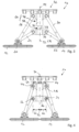
- a transport device is designated overall by the reference numeral 10. This comprises a first drive body 12 and a second drive body 14.
- the drive bodies 12 and 14 can be controlled independently of one another, for example only along a transport axis 16 or across a transport plane 18.
- the first drive body 12 carries a first pivot axis 20, by means of which a first lifting rocker 24 and a first guide rocker 26 are pivotally connected.
- the second drive body 14 carries a second pivot axis 22, by means of which a second lifting rocker 28 and a second guide rocker 30 are pivotally connected.
- the first lifting arm 24 and the second lifting arm 28 are articulated to a cross member 36 via respective lifting body pivot bearings 32 and 34.
- the cross member 36 is connected to a bolt 38, which extends in the vertical direction and is connected to a working area 40 of a lifting body 42.
- the lifting body 42 has working sections 44, which serve, for example, to hold objects.
- the guide axis 54 and the lifting axis 52 are identical to each other, i.e. they are identical in terms of their position and orientation.
- the sleeve 50 forms a first guide element 56 and the bolt 38 forms a second guide element 58 of a linear guide 60.
- the lifting arms 24 and 28 preferably have the same length. Furthermore, it is preferred if the guide arms 26 and 30 have the same length, but are each longer than the lifting arms 24 and 28.
- the lifting body pivot bearings 32 and 34 are spaced at the level of the cross member 36 from the lifting axis 52 with first, mutually identical distances 62 from the lifting axis 52.
- the guide pivot bearings 46 and 48 are spaced from the guide axis 54 by second, mutually identical distances 64.
- the first distances 62 and the second distances 64 are also identical.
- the sleeve 50 For a particularly precise and low-friction guidance of the bolt 38 relative to the sleeve 50, it is possible for the sleeve 50 to carry plain bearing bushes 66, compare Figure 5 These can be made from a low-friction plastic, such as PTFE.
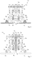
- the second guide element 58 for example in the form of the bolt 38, is directly and immovably connected to the useful area 40 of the lifting body 42 via a connecting area 68.
- an additional gear 70 is provided, which ensures that a lifting movement of the bolt 38 along the lifting axis 52 is not completely translated into a corresponding lifting movement of the useful area 40 of the lifting body 42.
- the lifting body 42 of the embodiment according to Figures 6 to 9 has a gripping device 72, which can be moved by means of the additional gear 70 between an open gripping position (see Figure 6 ) and a closed gripping position (compare Figure 8 ) can be operated.
- the additional gear 70 has two additional rockers 74, each of which is connected at one end to the second guide element 58, for example the bolt 38, and at the other end to actuating sections 76 of the gripping device 72.
- a movement of the second guide element 58 along the lifting axis 52 (compare starting from a state according to Figures 6 and 7 ) upwards (compare Figure 8 ) results in the second guide element 58 being raised along the lifting axis 52, whereby the additional rockers 74 are also raised and, as a result of their articulation on the actuating sections 76, actuate these actuating sections 76 in an actuating plane perpendicular to the lifting axis 52, whereby the gripping device 72 is closed.
- the required actuating stroke is shown in the drawing (see Figure 7 ) is designated by the reference numeral 78.
- the amount of the actuating stroke 78 corresponds to the displacement of the second guide element 58 along the stroke axis 52, without this displacement contributing to a stroke movement of the useful area 40.
- the device 10 has a locking gear 80.
- the locking gear 80 comprises a connecting rod 82, see Figure 7 , which is connected at one end to the working area 40 and at the other end to a boom 84 which, similar to the cross member 36, extends transversely to the lifting axis 52. It is preferred that the connecting rod 82 is arranged within the bolt 38, which in this case is hollow.
- the locking gear 80 further comprises two locking fingers 86, which are each pivotably connected to the guide rockers 28, 30 via bearings 88.
- the locking fingers 86 have a wedge-shaped engagement area 90 which is effective between the boom 84 of the useful area 40 and the cross member 36.
- the first guide element 56 is displaced along the guide axis 54.
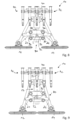
- the transport device 10 described has, in addition to the previously described transport devices 10, pivot bearings 92 and 94 respectively connected to the drive bodies 12, 14, which respectively define pivot axes 96, 98 extending perpendicular to the transport axis 16 or the transport plane 18.
- pivot bearings 92, 94 can also be used in the above-described embodiments according to Figures 1 to 9 be provided.
Landscapes
- Engineering & Computer Science (AREA)
- Mechanical Engineering (AREA)
- Robotics (AREA)
- Manipulator (AREA)
- Intermediate Stations On Conveyors (AREA)
Claims (13)
- Dispositif de transport (10), comprenant un premier corps d'entraînement (12), un second corps d'entraînement (14) et un corps de levage (42) pour la réception d'une charge utile, dans lequel les corps d'entraînement (12, 14) peuvent être commandés indépendamment l'un de l'autre le long d'un axe de transport (16) ou sur un plan de transport (18), dans lequel une première bielle de levage (24) est articulée de manière à pouvoir pivoter sur le premier corps d'entraînement (12) et une seconde bielle de levage (28) est articulée de manière à pouvoir pivoter sur le second corps d'entraînement (14), dans lequel les bielles de levage (24, 28) sont reliées de manière fonctionnelle au corps de levage (42), de sorte qu'un mouvement relatif des corps d'entraînement (12, 14) peut être transformé en un mouvement du corps de levage (42) le long d'un axe de levage (52), caractérisé en ce qu'une première bielle de guidage (26) est articulée de manière à pouvoir pivoter sur le premier corps d'entraînement (12), en ce qu'une seconde bielle de guidage (30) est articulée de manière à pouvoir pivoter sur le second corps d'entraînement (14), en ce que les bielles de guidage (26, 30) sont reliées à un premier élément de guidage (56), en ce que le corps de levage (42) présente un second élément de guidage (58), et en ce que les éléments de guidage (56, 58) forment un guidage linéaire (60) comportant un axe de guidage (54) qui coïncide avec l'axe de levage (52).
- Dispositif de transport (10) selon la revendication 1,
caractérisé en ce que l'axe de levage (52) est orienté perpendiculairement à l'axe de transport (16) ou au plan de transport (18). - Dispositif de transport (10) selon l'une des revendications précédentes, caractérisé en ce que le premier élément de guidage (56) est formé par un manchon (50) ou un rail.
- Dispositif de transport (10) selon l'une des revendications précédentes, caractérisé en ce que le second élément de guidage (58) est formé par un boulon (38) ou un coulisseau.
- Dispositif de transport (10) selon l'une des revendications précédentes, caractérisé en ce que les bielles de guidage (26, 30) sont plus longues que les bielles de levage (24, 28).
- Dispositif de transport (10) selon l'une des revendications précédentes, caractérisé en ce que les bielles de levage (24, 28) sont de même longueur et/ou en ce que les bielles de guidage (26, 30) sont de même longueur.
- Dispositif de transport (10) selon l'une des revendications précédentes, caractérisé en ce que la première bielle de levage (24) et la première bielle de guidage (26) peuvent pivoter sur le premier corps d'entraînement (12) autour d'un premier axe de pivotement commun (20) et/ou en ce que la seconde bielle de levage (28) et la seconde bielle de guidage (30) peuvent pivoter sur le second corps d'entraînement (14) autour d'un second axe de pivotement commun (22).
- Dispositif de transport (10) selon la revendication 7,
caractérisé en ce que le premier corps d'entraînement (12) présente un premier palier rotatif (92) comportant un premier axe de rotation (96) parallèle à l'axe de levage (52) et en ce que le premier axe de pivotement (20) est monté de manière à pouvoir tourner autour du premier axe de rotation (96) et/ou en ce que le second corps d'entraînement (14) présente un second palier rotatif (94) comportant un second axe de rotation (98) parallèle à l'axe de levage (52) et en ce que le second axe de pivotement (22) est monté de manière à pouvoir tourner autour du second axe de rotation (98). - Dispositif de transport (10) selon l'une des revendications précédentes, caractérisé en ce que les bielles de levage (24, 28) sont articulées, à leurs extrémités respectivement espacées des corps d'entraînement (12, 14), sur des paliers de pivotement de corps de levage (32, 34) qui sont disposés à des premières distances (62) identiques entre elles par rapport à l'axe de levage (52), et/ou en ce que les bielles de guidage (26, 30) sont articulées, à leurs extrémités respectivement espacées des corps d'entraînement (12, 14), sur des paliers de pivotement de guidage (46, 48) qui sont disposés à des secondes distances (64) identiques entre elles par rapport à l'axe de guidage (54).
- Dispositif de transport (10) selon la revendication 9,
caractérisé en ce que les premières distances (62) et les secondes distances (64) sont identiques. - Dispositif de transport (10) selon l'une des revendications précédentes, caractérisé en ce que le corps de levage (42) présente une zone utile (40) et un dispositif de préhension (72) et en ce que le second élément de guidage (58) et la zone utile (40) sont reliés entre eux par l'intermédiaire d'un engrenage supplémentaire (70) qui fournit, sur une course d'actionnement (78), une mobilité du second élément de guidage (58) par rapport à la zone utile (40) le long de l'axe de levage (52), dans lequel le dispositif de préhension (72) peut être transféré d'une position de préhension ouverte à une position de préhension fermée au moyen de la course d'actionnement (78).
- Dispositif de transport (10) selon la revendication 11,
caractérisé en ce qu'un engrenage de blocage (80) est prévu, lequel agit entre au moins l'une des bielles de guidage (26, 30) et un bras (84) de la zone utile (40) et lequel bloque un mouvement de levage de la zone utile (40) avant la fin de la course d'actionnement (78). - Dispositif de transport (10) selon la revendication 12,
caractérisé en ce que l'engrenage de blocage (80) comprend au moins un doigt de blocage (86) articulé de manière à pouvoir pivoter sur l'une des bielles de guidage (26, 30) et qui agit au moins pendant la course d'actionnement (78) entre le bras (84) de la zone utile (40) et une traverse (36) reliée au second élément de guidage (58).
Applications Claiming Priority (1)
| Application Number | Priority Date | Filing Date | Title |
|---|---|---|---|
| DE102022124050.9A DE102022124050B3 (de) | 2022-09-20 | 2022-09-20 | Transportvorrichtung |
Publications (2)
| Publication Number | Publication Date |
|---|---|
| EP4342829A1 EP4342829A1 (fr) | 2024-03-27 |
| EP4342829B1 true EP4342829B1 (fr) | 2025-04-30 |
Family
ID=88068618
Family Applications (1)
| Application Number | Title | Priority Date | Filing Date |
|---|---|---|---|
| EP23197301.7A Active EP4342829B1 (fr) | 2022-09-20 | 2023-09-14 | Dispositif de transport |
Country Status (6)
| Country | Link |
|---|---|
| US (1) | US12420435B2 (fr) |
| EP (1) | EP4342829B1 (fr) |
| CN (1) | CN117735175A (fr) |
| CA (1) | CA3212393A1 (fr) |
| DE (1) | DE102022124050B3 (fr) |
| ES (1) | ES3032532T3 (fr) |
Family Cites Families (25)
| Publication number | Priority date | Publication date | Assignee | Title |
|---|---|---|---|---|
| SE419958B (sv) * | 1979-12-28 | 1981-09-07 | Volvo Ab | Rorelsemekanism for en retlinjig rorelse med i endarna anslutande vinkelreta rorelsedelar |
| DE3404553C2 (de) | 1984-02-09 | 1986-04-17 | Carl Hurth Maschinen- und Zahnradfabrik GmbH & Co, 8000 München | Handhabungseinrichtung, insbesondere zum Be- und Entladen von Werkzeugmaschinen |
| KR940006941B1 (ko) | 1989-10-03 | 1994-07-30 | 가부시끼가이샤 야스가와 덴끼 세이사꾸쇼 | 면펄스 모우터를 사용한 매니풀레이터 |
| JP2558080B2 (ja) * | 1994-11-02 | 1996-11-27 | 株式会社奈和精機製作所 | 搬送装置 |
| US20020182036A1 (en) * | 2001-06-04 | 2002-12-05 | Applied Materials, Inc. | Semiconductor wafer handling robot for linear transfer chamber |
| DE102004023525B4 (de) * | 2004-05-13 | 2006-07-20 | Erdrich Beteiligungs Gmbh | Vorrichtung zum schrittweisen Verschieben von Werkstücken |
| DE102006038505A1 (de) * | 2006-08-16 | 2008-02-21 | Kmb Produktions Ag | Vorrichtung zum Versetzen von Gegenständen |
| US8104710B2 (en) * | 2007-04-25 | 2012-01-31 | Goodrich Actuation Systems Limited | Actuator arrangement |
| US8132518B2 (en) * | 2007-05-11 | 2012-03-13 | Siemens Medical Solutions Usa, Inc. | Substantially linear vertical lift system |
| DE102008022994B3 (de) * | 2008-05-09 | 2009-06-04 | Erdrich Beteiligungs Gmbh | Presse mit einer Transfereinrichtung zum schrittweisen Verschieben der Werkstücke und mit einer Greiferschienenkupplung |
| JP5476507B2 (ja) * | 2011-03-30 | 2014-04-23 | スキューズ株式会社 | スコットラッセル機構式装置 |
| DE102011118216B4 (de) * | 2011-11-11 | 2013-09-19 | Schuler Pressen Gmbh | Antriebseinrichtung für einen mehrachsigen Transport von Werkstücken durch aufeinander folgende Bearbeitungsstationen einer Bearbeitungsmaschine |
| AU2015247798B2 (en) * | 2014-04-14 | 2018-02-22 | Ergotron, Inc. | Height adjustable desktop work surface |
| DE102014010917B4 (de) * | 2014-07-28 | 2016-04-07 | Sew-Eurodrive Gmbh & Co Kg | Antriebsvorrichtung mit einem stationären Teil und mit N Linearachsen und Verfahren zum Betreiben der Antriebsvorrichtung |
| DE102016010190B4 (de) * | 2015-08-25 | 2023-08-24 | Saadat Mohsen | Greifmechanismus mit großem Hub |
| DE102015116808B3 (de) * | 2015-10-02 | 2017-01-19 | Beckhoff Automation Gmbh | Roboter, XY-Tisch für einen solchen Roboter und lineares Transportsystem |
| EP3358988A1 (fr) * | 2015-10-08 | 2018-08-15 | Ergotron, Inc. | Table réglable en hauteur |
| JP6192131B2 (ja) * | 2015-12-10 | 2017-09-06 | アイダエンジニアリング株式会社 | プレス機械のワーク搬送装置 |
| DE102016211169A1 (de) * | 2016-06-22 | 2017-12-28 | Krones Aktiengesellschaft | Vorrichtung zum Umgang mit Artikeln |
| US10926418B2 (en) | 2017-03-27 | 2021-02-23 | Planar Motor Incorporated | Robotic devices and methods for fabrication, use and control of same |
| DE102019101290C5 (de) * | 2019-01-18 | 2023-03-23 | Winkler und Dünnebier Süßwarenmaschinen GmbH | Transportsystem für eine industrielle Süßwarenmaschine |
| JP7370233B2 (ja) * | 2019-11-29 | 2023-10-27 | 東京エレクトロン株式会社 | 基板搬送装置及び基板処理システム |
| JP7433159B2 (ja) * | 2020-07-30 | 2024-02-19 | 東京エレクトロン株式会社 | 真空搬送装置、基板処理システム、および基板処理方法 |
| JP2022107898A (ja) * | 2021-01-12 | 2022-07-25 | 東京エレクトロン株式会社 | 基板搬送装置、基板搬送方法、および基板処理システム |
| JP7519923B2 (ja) * | 2021-01-12 | 2024-07-22 | 東京エレクトロン株式会社 | 基板搬送装置、基板搬送方法、および基板処理システム |
-
2022
- 2022-09-20 DE DE102022124050.9A patent/DE102022124050B3/de active Active
-
2023
- 2023-09-13 CA CA3212393A patent/CA3212393A1/fr active Pending
- 2023-09-14 EP EP23197301.7A patent/EP4342829B1/fr active Active
- 2023-09-14 ES ES23197301T patent/ES3032532T3/es active Active
- 2023-09-15 US US18/468,081 patent/US12420435B2/en active Active
- 2023-09-19 CN CN202311214272.7A patent/CN117735175A/zh active Pending
Also Published As
| Publication number | Publication date |
|---|---|
| CA3212393A1 (fr) | 2024-03-20 |
| CN117735175A (zh) | 2024-03-22 |
| US20240091959A1 (en) | 2024-03-21 |
| US12420435B2 (en) | 2025-09-23 |
| DE102022124050B3 (de) | 2023-12-07 |
| ES3032532T3 (en) | 2025-07-21 |
| EP4342829A1 (fr) | 2024-03-27 |
Similar Documents
| Publication | Publication Date | Title |
|---|---|---|
| DE69604140T2 (de) | Positioniermechanismus mit mehreren Freiheitsgraden | |
| EP2493663B1 (fr) | Pince de montage avec cliquet d'arret libérable | |
| EP4342829B1 (fr) | Dispositif de transport | |
| DE2821635C2 (de) | Hubvorrichtung | |
| DE102012212337B4 (de) | Manipulator oder dergleichen | |
| DE3934972A1 (de) | Parallelgreiferantrieb fuer handhabungsgeraete | |
| EP3266393B1 (fr) | Instrument chirurgical | |
| DE69607645T2 (de) | Mehrzweckzange | |
| DE1802380C3 (de) | Greifvorrichtung einer Werkstückfördereinrichtung | |
| DE3318398A1 (de) | Handhabungsvorrichtung | |
| EP4108387B1 (fr) | Dispositif d'entraînement planaire et procédé permettant de faire fonctionner un dispositif d'entraînement planaire | |
| DE2702144A1 (de) | Betaetigungsvorrichtung fuer zwei hydraulische ventile | |
| DE102006002830B4 (de) | Ausstellvorrichtung für den Flügel eines Fensters oder dergleichen | |
| EP3189725B1 (fr) | Dispositif de traitement de matières coupées agricoles ou forestiers | |
| DE2306127C3 (de) | Scheibenwischeranlage | |
| DE102020208430B4 (de) | Schmiedemaschinen-Belade- und -Entladevorrichtung | |
| DE2757667A1 (de) | Antriebsvorrichtung fuer die nadel einer naehmaschine | |
| DE19927728C1 (de) | Greifermechanismus für Einrichtungen zur Handhabung blattartiger oder plattenartiger Gegenstände, insbesondere für Postbearbeitungsmaschinen | |
| DE202008004849U1 (de) | Handbetätigendes Zangenwerkzeug | |
| DE102023125303A1 (de) | F2-Roboter mit zusätzlichem Kopplungsmittel in der Parallelogramm-Führung der Roboter-Hand | |
| DE290352C (fr) | ||
| DE3050483C2 (fr) | ||
| EP3372176B1 (fr) | Instrument médical | |
| EP0385193A2 (fr) | Pince de préhension pour manipulateurs | |
| DE4407432A1 (de) | Motorkettensäge |
Legal Events
| Date | Code | Title | Description |
|---|---|---|---|
| PUAI | Public reference made under article 153(3) epc to a published international application that has entered the european phase |
Free format text: ORIGINAL CODE: 0009012 |
|
| STAA | Information on the status of an ep patent application or granted ep patent |
Free format text: STATUS: THE APPLICATION HAS BEEN PUBLISHED |
|
| AK | Designated contracting states |
Kind code of ref document: A1 Designated state(s): AL AT BE BG CH CY CZ DE DK EE ES FI FR GB GR HR HU IE IS IT LI LT LU LV MC ME MK MT NL NO PL PT RO RS SE SI SK SM TR |
|
| STAA | Information on the status of an ep patent application or granted ep patent |
Free format text: STATUS: REQUEST FOR EXAMINATION WAS MADE |
|
| 17P | Request for examination filed |
Effective date: 20240926 |
|
| RBV | Designated contracting states (corrected) |
Designated state(s): AL AT BE BG CH CY CZ DE DK EE ES FI FR GB GR HR HU IE IS IT LI LT LU LV MC ME MK MT NL NO PL PT RO RS SE SI SK SM TR |
|
| GRAP | Despatch of communication of intention to grant a patent |
Free format text: ORIGINAL CODE: EPIDOSNIGR1 |
|
| STAA | Information on the status of an ep patent application or granted ep patent |
Free format text: STATUS: GRANT OF PATENT IS INTENDED |
|
| RIC1 | Information provided on ipc code assigned before grant |
Ipc: B65G 54/02 20060101ALI20250129BHEP Ipc: B25J 9/10 20060101ALI20250129BHEP Ipc: B25J 5/00 20060101ALI20250129BHEP Ipc: B65G 47/90 20060101AFI20250129BHEP |
|
| INTG | Intention to grant announced |
Effective date: 20250213 |
|
| GRAS | Grant fee paid |
Free format text: ORIGINAL CODE: EPIDOSNIGR3 |
|
| GRAA | (expected) grant |
Free format text: ORIGINAL CODE: 0009210 |
|
| STAA | Information on the status of an ep patent application or granted ep patent |
Free format text: STATUS: THE PATENT HAS BEEN GRANTED |
|
| AK | Designated contracting states |
Kind code of ref document: B1 Designated state(s): AL AT BE BG CH CY CZ DE DK EE ES FI FR GB GR HR HU IE IS IT LI LT LU LV MC ME MK MT NL NO PL PT RO RS SE SI SK SM TR |
|
| REG | Reference to a national code |
Ref country code: CH Ref legal event code: EP Ref country code: GB Ref legal event code: FG4D Free format text: NOT ENGLISH |
|
| REG | Reference to a national code |
Ref country code: DE Ref legal event code: R096 Ref document number: 502023000909 Country of ref document: DE |
|
| REG | Reference to a national code |
Ref country code: IE Ref legal event code: FG4D Free format text: LANGUAGE OF EP DOCUMENT: GERMAN |
|
| REG | Reference to a national code |
Ref country code: ES Ref legal event code: FG2A Ref document number: 3032532 Country of ref document: ES Kind code of ref document: T3 Effective date: 20250721 |
|
| REG | Reference to a national code |
Ref country code: NL Ref legal event code: MP Effective date: 20250430 |
|
| REG | Reference to a national code |
Ref country code: DE Ref legal event code: R081 Ref document number: 502023000909 Country of ref document: DE Owner name: SYNTEGON TECHNOLOGY GMBH, DE Free format text: FORMER OWNER: SYNTEGON TECHNOLOGY GMBH, 71332 WAIBLINGEN, DE |
|
| REG | Reference to a national code |
Ref country code: CH Ref legal event code: W10 Free format text: ST27 STATUS EVENT CODE: U-0-0-W10-W00 (AS PROVIDED BY THE NATIONAL OFFICE) Effective date: 20251006 |
|
| PG25 | Lapsed in a contracting state [announced via postgrant information from national office to epo] |
Ref country code: FI Free format text: LAPSE BECAUSE OF FAILURE TO SUBMIT A TRANSLATION OF THE DESCRIPTION OR TO PAY THE FEE WITHIN THE PRESCRIBED TIME-LIMIT Effective date: 20250430 Ref country code: PT Free format text: LAPSE BECAUSE OF FAILURE TO SUBMIT A TRANSLATION OF THE DESCRIPTION OR TO PAY THE FEE WITHIN THE PRESCRIBED TIME-LIMIT Effective date: 20250901 |
|
| PGFP | Annual fee paid to national office [announced via postgrant information from national office to epo] |
Ref country code: DE Payment date: 20250919 Year of fee payment: 3 |
|
| REG | Reference to a national code |
Ref country code: LT Ref legal event code: MG9D |
|
| PG25 | Lapsed in a contracting state [announced via postgrant information from national office to epo] |
Ref country code: GR Free format text: LAPSE BECAUSE OF FAILURE TO SUBMIT A TRANSLATION OF THE DESCRIPTION OR TO PAY THE FEE WITHIN THE PRESCRIBED TIME-LIMIT Effective date: 20250731 Ref country code: NO Free format text: LAPSE BECAUSE OF FAILURE TO SUBMIT A TRANSLATION OF THE DESCRIPTION OR TO PAY THE FEE WITHIN THE PRESCRIBED TIME-LIMIT Effective date: 20250730 |
|
| PG25 | Lapsed in a contracting state [announced via postgrant information from national office to epo] |
Ref country code: NL Free format text: LAPSE BECAUSE OF FAILURE TO SUBMIT A TRANSLATION OF THE DESCRIPTION OR TO PAY THE FEE WITHIN THE PRESCRIBED TIME-LIMIT Effective date: 20250430 Ref country code: PL Free format text: LAPSE BECAUSE OF FAILURE TO SUBMIT A TRANSLATION OF THE DESCRIPTION OR TO PAY THE FEE WITHIN THE PRESCRIBED TIME-LIMIT Effective date: 20250430 |
|
| PG25 | Lapsed in a contracting state [announced via postgrant information from national office to epo] |
Ref country code: BG Free format text: LAPSE BECAUSE OF FAILURE TO SUBMIT A TRANSLATION OF THE DESCRIPTION OR TO PAY THE FEE WITHIN THE PRESCRIBED TIME-LIMIT Effective date: 20250430 |
|
| PG25 | Lapsed in a contracting state [announced via postgrant information from national office to epo] |
Ref country code: HR Free format text: LAPSE BECAUSE OF FAILURE TO SUBMIT A TRANSLATION OF THE DESCRIPTION OR TO PAY THE FEE WITHIN THE PRESCRIBED TIME-LIMIT Effective date: 20250430 |
|
| PGFP | Annual fee paid to national office [announced via postgrant information from national office to epo] |
Ref country code: AT Payment date: 20251020 Year of fee payment: 3 |
|
| PG25 | Lapsed in a contracting state [announced via postgrant information from national office to epo] |
Ref country code: RS Free format text: LAPSE BECAUSE OF FAILURE TO SUBMIT A TRANSLATION OF THE DESCRIPTION OR TO PAY THE FEE WITHIN THE PRESCRIBED TIME-LIMIT Effective date: 20250731 |
|
| PG25 | Lapsed in a contracting state [announced via postgrant information from national office to epo] |
Ref country code: IS Free format text: LAPSE BECAUSE OF FAILURE TO SUBMIT A TRANSLATION OF THE DESCRIPTION OR TO PAY THE FEE WITHIN THE PRESCRIBED TIME-LIMIT Effective date: 20250830 |
|
| PG25 | Lapsed in a contracting state [announced via postgrant information from national office to epo] |
Ref country code: LV Free format text: LAPSE BECAUSE OF FAILURE TO SUBMIT A TRANSLATION OF THE DESCRIPTION OR TO PAY THE FEE WITHIN THE PRESCRIBED TIME-LIMIT Effective date: 20250430 |
|
| RAP4 | Party data changed (patent owner data changed or rights of a patent transferred) |
Owner name: SYNTEGON TECHNOLOGY GMBH |