EP4338645B1 - Rauchlose brat- und backmaschine und steuerungsverfahren dafür - Google Patents
Rauchlose brat- und backmaschine und steuerungsverfahren dafür Download PDFInfo
- Publication number
- EP4338645B1 EP4338645B1 EP22936988.9A EP22936988A EP4338645B1 EP 4338645 B1 EP4338645 B1 EP 4338645B1 EP 22936988 A EP22936988 A EP 22936988A EP 4338645 B1 EP4338645 B1 EP 4338645B1
- Authority
- EP
- European Patent Office
- Prior art keywords
- rotating speed
- baking
- frying
- tray
- fan component
- Prior art date
- Legal status (The legal status is an assumption and is not a legal conclusion. Google has not performed a legal analysis and makes no representation as to the accuracy of the status listed.)
- Active
Links
Images


Classifications
-
- A—HUMAN NECESSITIES
- A47—FURNITURE; DOMESTIC ARTICLES OR APPLIANCES; COFFEE MILLS; SPICE MILLS; SUCTION CLEANERS IN GENERAL
- A47J—KITCHEN EQUIPMENT; COFFEE MILLS; SPICE MILLS; APPARATUS FOR MAKING BEVERAGES
- A47J36/00—Parts, details or accessories of cooking-vessels
- A47J36/32—Time-controlled igniting mechanisms or alarm devices
-
- A—HUMAN NECESSITIES
- A47—FURNITURE; DOMESTIC ARTICLES OR APPLIANCES; COFFEE MILLS; SPICE MILLS; SUCTION CLEANERS IN GENERAL
- A47J—KITCHEN EQUIPMENT; COFFEE MILLS; SPICE MILLS; APPARATUS FOR MAKING BEVERAGES
- A47J37/00—Baking; Roasting; Grilling; Frying
- A47J37/06—Roasters; Grills; Sandwich grills
- A47J37/0611—Roasters; Grills; Sandwich grills the food being cooked between two heating plates, e.g. waffle-irons
-
- A—HUMAN NECESSITIES
- A47—FURNITURE; DOMESTIC ARTICLES OR APPLIANCES; COFFEE MILLS; SPICE MILLS; SUCTION CLEANERS IN GENERAL
- A47J—KITCHEN EQUIPMENT; COFFEE MILLS; SPICE MILLS; APPARATUS FOR MAKING BEVERAGES
- A47J37/00—Baking; Roasting; Grilling; Frying
- A47J37/06—Roasters; Grills; Sandwich grills
- A47J37/0623—Small-size cooking ovens, i.e. defining an at least partially closed cooking cavity
- A47J37/0629—Small-size cooking ovens, i.e. defining an at least partially closed cooking cavity with electric heating elements
- A47J37/0641—Small-size cooking ovens, i.e. defining an at least partially closed cooking cavity with electric heating elements with forced air circulation, e.g. air fryers
-
- A—HUMAN NECESSITIES
- A47—FURNITURE; DOMESTIC ARTICLES OR APPLIANCES; COFFEE MILLS; SPICE MILLS; SUCTION CLEANERS IN GENERAL
- A47J—KITCHEN EQUIPMENT; COFFEE MILLS; SPICE MILLS; APPARATUS FOR MAKING BEVERAGES
- A47J37/00—Baking; Roasting; Grilling; Frying
- A47J37/06—Roasters; Grills; Sandwich grills
- A47J37/0623—Small-size cooking ovens, i.e. defining an at least partially closed cooking cavity
- A47J37/0664—Accessories
-
- A—HUMAN NECESSITIES
- A47—FURNITURE; DOMESTIC ARTICLES OR APPLIANCES; COFFEE MILLS; SPICE MILLS; SUCTION CLEANERS IN GENERAL
- A47J—KITCHEN EQUIPMENT; COFFEE MILLS; SPICE MILLS; APPARATUS FOR MAKING BEVERAGES
- A47J37/00—Baking; Roasting; Grilling; Frying
- A47J37/10—Frying pans, e.g. frying pans with integrated lids or basting devices
- A47J37/101—Integrated lids
- A47J37/103—Broiling- or heating-lids
-
- A—HUMAN NECESSITIES
- A47—FURNITURE; DOMESTIC ARTICLES OR APPLIANCES; COFFEE MILLS; SPICE MILLS; SUCTION CLEANERS IN GENERAL
- A47J—KITCHEN EQUIPMENT; COFFEE MILLS; SPICE MILLS; APPARATUS FOR MAKING BEVERAGES
- A47J37/00—Baking; Roasting; Grilling; Frying
- A47J37/10—Frying pans, e.g. frying pans with integrated lids or basting devices
- A47J37/108—Accessories, e.g. inserts, plates to hold food down during frying
Definitions
- the smokeless baking tray in the market generally uses the design of a circulating air channel. It is troublesome to remove a fan and an air channel. It is easy for dirt and filth in the circulating air channel to breed bacteria and produce peculiar smell. The flowing air will circulate through the food after circulating through the air channel, so that it is easy for food to be contaminated with bacteria and peculiar smell, thus affecting food sanitation.
- CN112220332 shows a cooking system with two cooking plates and an angle sensor, and also discloses determining the position of the two cooking parts and controlling the device to operate differently according to the position relationship.
- the present disclosure aims at solving at least one of the technical problems existing in the prior art. To this end, the present disclosure provides a smokeless frying and baking machine and a control method thereof, and uses the following technical scheme.
- a smokeless frying and baking machine comprises:
- the air channel is provided with two air inlets, and the two air inlets are both provided at the rear side of the lower shell and are distributed at intervals from front to back.
- the two air inlets comprise a first air inlet and a second air inlet, respectively, and when the first air inlet is located above the lower baking tray and the upper baking tray is distributed in the position of unfolding the tray, the second air inlet is located above the upper baking tray.
- the smokeless frying and baking machine further comprises a filtered water box, wherein the filtered water box is provided with an air intake and an air vent communicated with the inside thereof, the filtered water box is provided at the outlet of the air channel and is communicated with the air channel through the air intake, and the air vent is communicated with the outside.
- the filtered water box is provided with an air intake and an air vent communicated with the inside thereof, the filtered water box is provided at the outlet of the air channel and is communicated with the air channel through the air intake, and the air vent is communicated with the outside.
- the rotating speed detection component comprises a speed measuring sensor
- the speed measuring sensor is a Hall sensor or a photoelectric sensor
- the fan component comprises a motor and a wind wheel mounted at the output end of the motor
- the rotating speed detection component is mounted on the wind wheel and is configured to detect the rotating speed of the wind wheel
- the motor and the rotating speed detection component are electrically connected with the controller, respectively.
- the smokeless frying and baking machine further comprises an oil receiving tray, wherein the air channel is provided with an oil leakage hole on a side wall below the fan component, and the oil receiving tray is mounted on the lower shell and is located below the oil leakage hole.
- the smokeless frying and baking machine further comprises two oil baffle plates, and the two oil baffle plates are detachably provided on both sides of the lower shell.
- the oil baffle plates are in magnetic adsorption connection with the lower shell.
- the present disclosure further provides a control method based on the smokeless frying and baking machine, comprising the following steps:
- the rotating speed of the fan component is regulated according to the size of the frying and baking cavity, and the cooking duration of the current cooking stage is compensated according to the actual rotating speed of the fan component, so as to ensure the kitchen ventilator effect and the cooking effect of the frying and baking machine.
- a plurality of means more than two, and “greater than, less than, more than, etc.” are understood as excluding this number, and above, below, within, etc. are understood as including this number. If the first and second descriptions are only used for the purpose of distinguishing technical features, the descriptions cannot be understood as indicating or implying relative importance, implicitly indicating the number of indicated technical features, or implicitly indicating the sequence of indicated technical features.
- the terms such as “provide”, “mount” and “connect” should be understood broadly, for example, it can be direct connection or indirect connection through an intermediate medium; fixed connection, detachable connection or integral connection; mechanical connection; or the internal communication of two elements or the interaction between two elements. Those skilled in the art can reasonably determine the specific meaning of the above terms in the present disclosure in combination with the specific content of the technical scheme.
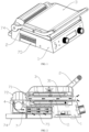
- Embodiment 1 of the present disclosure discloses a smokeless frying and baking machine, comprising:
- the controller is configured to receive the change of the angle between the handle 2 and the upper shell 3, calculate the actual volume of the frying and baking cavity according to the angle change, compare the actual volume with the maximum volume, if the actual volume is less than or equal to the maximum volume, calculate the desired rotating speed corresponding to the actual volume, and control the fan component 4 to run at the desired rotating speed.
- the controller receives the actual rotating speed detected by the rotating speed detection component 6, calculates the desired cooking duration of the current cooking stage of the frying and baking machine according to the actual rotating speed of the fan component, and adjusts the duration of the current cooking stage of the frying and baking machine as the desired cooking duration; and if the actual volume is greater than the maximum volume, adjusts the rotating speed of the fan component to the maximum rotating speed until the end of the current cooking stage.
- the working principle of the smokeless frying and baking machine in this embodiment is as follows.
- the fan component 4 When the upper shell 3 rotates to the position of combining the tray or unfolding the tray close to the lower shell 1, the fan component 4 generates negative pressure in the air channel 7, so that the oil smoke generated on the upper baking tray 31 and the lower baking tray 11 is sucked and discharged from the air channel 7.
- the angle detection component 5 detects the change of the angle between the handle 2 and the upper shell 3 and sends the change to the controller. According to the change of the angle between the handle 2 and the upper shell 3, the actual volume of the frying and baking cavity is calculated, and the desired rotating speed of the fan component 4 is calculated. The controller then sends a signal to the fan component 4 to adjust the rotating speed of the fan component 4. Therefore, the rotating speed of the fan component 4 is regulated according to the size of the frying and baking cavity, so as to ensure the kitchen ventilator effect of the frying and baking machine. Meanwhile, the rotating speed detection component 6 detects the actual rotating speed of the fan component 4.
- the controller compensates for the cooking duration of the current cooking stage according to the desired actual rotating speed of the fan component 4, so as to prevent the fast air flow speed from affecting cooking and ensure the cooking effect of the frying and baking machine.
- the rotating speed detection component 6 can detect the actual rotating speed of the fan component 4, so as to prevent the calculation error of the desired cooking duration caused by the difference between the actual rotating speed of the fan component 4 and the desired rotating speed, and ensure the cooking effect of the frying and baking machine.
- the desired rotating speed of the fan component 4 is 2000r/min
- the actual rotating speed of the fan component 4 detected by the rotating speed detection component 6 is 1900r/min
- the floating component is used to keep the upper baking tray 31 horizontal.
- the handle 2 is mounted on the upper shell 3 by a floating component to keep horizontal, which belongs to the conventional technology in the field.
- the structure of the floating component is not specifically defined in the present disclosure.
- the angle detection component 5 is an angle sensor.
- One end of the rotating shaft is connected with the floating component.
- the angle sensor is mounted at the other end of the rotating shaft.
- the angle sensor is provided with an inner ring and an outer ring which can rotate relatively.
- the inner ring is coaxially and fixedly connected with the rotating shaft, and the outer ring is fixedly connected with the handle.
- the angle sensor is configured to detect the change of the angle between the inner ring and the outer ring and send the corresponding resistance change value ⁇ R to the controller, so that the controller calculates the volume of the frying and baking cavity according to the resistance change value ⁇ R.
- the air channel 7 is provided with two air inlets, and the two air inlets are distributed on one side of the lower shell 1 close to and far away from the frying and baking cavity.
- the two air inlets are distributed between the upper tray 31 and the lower tray 11, which is suitable for the kitchen ventilator when the frying and baking machine is in the position of combining the tray and unfolding the tray.
- the two air inlets comprise a first air inlet 71 and a second air inlet 72, respectively, and when the first air inlet 71 is located above the lower baking tray 11 and the upper baking tray 31 is distributed in the position of unfolding the tray, the second air inlet 72 is located above the upper baking tray 31.
- the first air inlet 71 When the first air inlet 71 is located above the lower baking tray 11, or the second air inlet 72 is distributed above the upper baking tray 31 in the position of unfolding the tray, the first air inlet 71 or the second air inlet 72 has a better suction effect on the oil smoke generated on the upper baking tray 31 and the lower baking tray 11.
- the frying and baking machine further comprises a filter grille 73.
- the filter grille 73 is mounted on the lower shell 1 and is located at the entrance of the air channel 7.
- the filter grille 73 is provided with ventilation holes penetrating therethrough, and the ventilation holes form the air inlet.
- the front side and the rear side of the filter grille 73 are provided with ventilation holes, respectively, and the ventilation holes on the front side and the rear side form the first air inlet 71 and the second air inlet 72, respectively.
- the filter grille 73 can preliminarily filter the steam and oil mist in the oil smoke.
- the smokeless frying and baking machine further comprises a filtered water box 75, the filtered water box 75 is provided with an air intake and an air vent communicated with the inside thereof, the filtered water box 75 is provided at the outlet of the air channel 7 and is communicated with the air channel 7 through the air intake, and the air vent is communicated with the outside.
- air vents are provided on both side walls of the filtered water box, and the upper end of the filtered water box is provided with a notch to form an air intake.
- the oil smoke in the air channel 7 is filtered by the water surface in the filtered water box 75 and then is discharged from the lower shell 1, so that the oil smoke and water vapor are discharged after double filtration, which greatly reduces the harm of oil smoke and the like to human health, and reduces the secondary pollution caused by circulating air to food materials because the air channel 7 is not designed as a circulating air channel 7.
- the rotating speed detection component 6 comprises a speed measuring sensor
- the speed measuring sensor is a Hall sensor or a photoelectric sensor
- the fan component 4 comprises a variable-frequency motor 41 and a wind wheel 42 mounted at the output end of the variable-frequency motor 41
- the rotating speed detection component 6 is mounted on the wind wheel 42 and is configured to detect the rotating speed of the wind wheel 42
- the variable-frequency motor 41 and the rotating speed detection component 6 are electrically connected with the controller, respectively.
- the rotating speed measuring sensor is configured to detect the rotating speed of the wind wheel 42 and send the rotating speed to the controller.
- the controller controls the variable-frequency motor 41 according to the real-time rotating speed of the wind wheel 42, so that the rotating speed of the wind wheel 42 can accurately reach the set rotating speed.
- the oil receiving tray 74 is provided below the fan, which is convenient to collect and clean oils and fats.
- the smokeless frying and baking machine further comprises two oil baffle plates 8, and the two oil baffle plates 8 are detachably provided on both sides of the lower shell 1.
- the oil baffle plates 8 are in magnetic adsorption connection with the lower shell 1, preventing a large amount of oil from splashing on the table top. It is convenient to disassemble and wash the magnetically attracted oil baffle plate 8.
- the fan component 4 the filter grille 73, the oil receiving tray 74 and the filtered water box 75 are detachably mounted on the lower shell 1, which is convenient to clean.
- Vmax V 0 + Q 2 * ⁇ V
Landscapes
- Engineering & Computer Science (AREA)
- Food Science & Technology (AREA)
- Baking, Grill, Roasting (AREA)
Claims (10)
- Rauchfreie Brat- und Backmaschine, umfassend:ein unteres Gehäuse (1), das mit einem unteren Backblech (11) versehen ist;einen Griff (2), der drehbar an dem unteren Gehäuse (1) montiert ist;ein oberes Gehäuse (3), das mit einem oberen Backblech (31) versehen ist, wobei das obere Gehäuse (3) drehbar an den Griff (2) durch eine schwimmende Komponente montiert ist, und der Griff (2) dazu konfiguriert ist, das obere Gehäuse (3) zum Vorwärts- und Rückwärtsdrehen anzutreiben, um dem unteren Gehäuse (1) derart nahe zu sein, dass das obere Backblech (31) und das untere Backblech (11) umschlossen sind, um einen Brat- und Backhohlraum zu bilden, oder von dem unteren Gehäuse (1) weg zu der Position des Aufklappens des Blechs zu drehen;eine Lüfterkomponente (4), wobei das untere Gehäuse (1) mit einem Luftkanal (7) versehen ist, die Lüfterkomponente (4) an das untere Gehäuse (1) montiert und dazu konfiguriert ist, Unterdruck in dem Luftkanal (7) zu erzeugen, um Ölrauch, der von dem unteren Backblech (11) und dem oberen Backblech (31) erzeugt wird, anzusaugen,eine Winkelerfassungskomponente (5), wobei die Winkelerfassungskomponente (5) zwischen dem Griff (2) und dem oberen Gehäuse (3) montiert und dazu konfiguriert ist, den Wechsel des Winkels zwischen dem Griff (2) und dem oberen Gehäuse (3) zu erfassen; gekennzeichnet durch:eine Drehzahlerfassungskomponente (6), wobei die Drehzahlerfassungskomponente (6) an die Lüfterkomponente (4) montiert und dazu konfiguriert ist, die tatsächliche Drehzahl der Lüfterkomponente (4) zu erfassen;eine Steuervorrichtung, die an das untere Gehäuse (1) montiert ist und elektrisch jeweils mit der Lüfterkomponente (4), der Winkelerfassungskomponente (5) und der Drehzahlerfassungskomponente (6) verbunden ist, wobei die Steuervorrichtung dazu konfiguriert ist, das tatsächliche Volumen des Brat- und Backvolumens gemäß der Winkeländerung zu berechnen, wenn das tatsächliche Volumen geringer ist als das maximale Volumen, die Drehzahl der Lüfterkomponente (4) gemäß der gewünschten Drehzahl zu steuern, die aus dem tatsächlichen Volumen berechnet wird, und dann die gewünschte Garzeit der aktuellen Garstufe der Brat- und Backmaschine gemäß der tatsächlichen Drehzahl zu berechnen.
- Rauchfreie Brat- und Backmaschine nach Anspruch 1, wobei der Luftkanal (7) mit zwei Lufteinlässen versehen ist, und die zwei Lufteinlässe beide an der Rückseite des unteren Gehäuses (1) bereitgestellt und in Abständen von vorn nach hinten verteilt sind.
- Rauchfreie Brat- und Backmaschine nach Anspruch 2, wobei die zwei Lufteinlässe einen ersten Lufteinlass (71) bzw. einen zweiten Lufteinlass (72) umfassen, und wenn sich der erste Lufteinlass (71) über dem unteren Backblech (11) befindet und das obere Backblech (31) in der Position des Aufklappens des Blechs verteilt ist, sich der zweite Lufteinlass (72) oberhalb des oberen Backblechs (31) befindet.
- Rauchfreie Brat- und Backmaschine nach Anspruch 1, die weiter einen Kasten (75) für gefiltertes Wasser umfasst, wobei der Kasten (75) für gefiltertes Wasser mit einem Lufteinlass und einem Luftauslass, die mit dem Inneren davon in Kommunikation stehen, versehen ist, der Kasten (75) für gefiltertes Wasser an dem Auslass des Luftkanals (7) bereitgestellt ist und mit dem Luftkanal (7) durch den Lufteinlass in Kommunikation steht, und der Luftauslass mit der Außenumgebung in Kommunikation steht.
- Rauchfreie Brat- und Backmaschine nach Anspruch 1, wobei die Drehzahlerfassungskomponente (6) einen Drehzahlmesssensor umfasst, der Drehzahlmesssensor ein Hall-Sensor oder ein fotoelektrischer Sensor ist, die Lüfterkomponente (4) einen Motor (41) und ein Windrad (42) umfasst, das an das Ausgangsende des Motors (41) montiert ist, die Drehzahlerfassungskomponente (6) an das Windrad (42) montiert und dazu konfiguriert ist, die Drehzahl des Windrades (42) zu erfassen, und der Motor (41) und die Drehzahlerfassungskomponente (6) elektrisch jeweils mit der Steuervorrichtung verbunden sind.
- Rauchfreie Brat- und Backmaschine nach Anspruch 1, die weiter ein Ölaufnahmeblech (74) umfasst, wobei der Luftkanal (7) mit einem Ölleckageloch an einer Seitenwand unter der Lüfterkomponente (4) versehen ist, und das Ölaufnahmeblech (74) an das untere Gehäuse (1) montiert ist und sich unter dem Ölleckageloch befindet.
- Rauchfreie Brat- und Backmaschine nach Anspruch 1, die weiter zwei Ölprallplatten (8) umfasst, und die zwei Ölprallplatten (8) lösbar an beiden Seiten des unteren Gehäuses (1) bereitgestellt sind.
- Rauchfreie Brat- und Backmaschine nach Anspruch 7, wobei die Ölprallplatten (8) in magnetischer Adsorptionsverbindung mit dem unteren Gehäuse (1) sind.
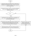
- Steuerverfahren der rauchfreien Brat- und Backmaschine nach Anspruch 1, das die folgenden Schritte umfasst:schritt 1, Erfassen der Änderung des Winkels zwischen einem Griff und einem oberen Gehäuse, und Berechnen des tatsächlichen Volumens Q1 eines Brat- und Backhohlraums, der durch Umschließen eines oberen Backblechs und eines unteren Backblechs gebildet ist,schritt 2, Voreinstellen des maximalen Volumens Q2 des Brat- und Backhohlraums, und Vergleichen des tatsächlichen Volumens Q1 mit dem maximalen Volumen Q2;wenn das tatsächliche Volumen Q1 kleiner oder gleich wie das maximale Volumen Q2 ist, Berechnen der gewünschten Drehzahl, die dem tatsächlichen Volumen entspricht, und Steuern der Lüfterkomponente, um mit einer gewünschten Drehzahl zu laufen;Berechnen der gewünschten Drehzahl V mit der Formel: V = V0+Q1 * ΔV, wobei V0 die voreingestellte Drehzahl in der aktuellen Garstufe ist, und ΔV die voreingestellte Drehzahlvariable ist, die mit dem Volumen des Brat- und Backhohlraums variiert;Erfassen der tatsächlichen Drehzahl V' der Lüfterkomponente und Berechnen der gewünschten Garzeit der aktuellen Garstufe der Brat- und Backmaschine gemäß der tatsächlichen Drehzahl V' der Lüfterkomponente;Berechnen der gewünschten Garzeit T mit der Formel: T = T0+ V' * ΔT, wobei T0 die voreingestellte Garzeit der aktuell Garstufe ist, und ΔT die voreingestellte Zeitvariable ist, die mit dem Volumen des Brat- und Backhohlraums variiert;Einstellen der Dauer der aktuellen Garstufe der Brat- und Backmaschine auf die gewünschte Garzeit;wenn das tatsächliche Volumen Q1 größer ist als das maximale Volumen Q2, Einstellen der Drehzahl der Lüfterkomponente auf die maximale Drehzahl bis zum Ende der aktuellen Garstufe.
- Steuerverfahren der rauchfreien Brat- und Backmaschine nach Anspruch 9, das die folgenden Schritte umfasst:Berechnen des tatsächlichen Volumens Q1 des Brat- und Backhohlraums, der durch das obere Backblech und das untere Backblech umschlossen ist, mit der Formel:
 wobei a die Länge eines Backblechs ist, b die Breite eines Backblechs ist, ΔR der Widerstandsänderungswert, der von einem Winkelsensor erfasst wird, ist, und m ein Mengenkoeffizient ist.
Applications Claiming Priority (2)
| Application Number | Priority Date | Filing Date | Title |
|---|---|---|---|
| CN202210394005.1A CN114831518B (zh) | 2022-04-15 | 2022-04-15 | 一种无烟煎烤机及其控制方法 |
| PCT/CN2022/087714 WO2023197343A1 (zh) | 2022-04-15 | 2022-04-19 | 一种无烟煎烤机及其控制方法 |
Publications (3)
| Publication Number | Publication Date |
|---|---|
| EP4338645A1 EP4338645A1 (de) | 2024-03-20 |
| EP4338645A4 EP4338645A4 (de) | 2024-07-24 |
| EP4338645B1 true EP4338645B1 (de) | 2025-03-19 |
Family
ID=82565581
Family Applications (1)
| Application Number | Title | Priority Date | Filing Date |
|---|---|---|---|
| EP22936988.9A Active EP4338645B1 (de) | 2022-04-15 | 2022-04-19 | Rauchlose brat- und backmaschine und steuerungsverfahren dafür |
Country Status (6)
| Country | Link |
|---|---|
| US (1) | US12564287B2 (de) |
| EP (1) | EP4338645B1 (de) |
| KR (1) | KR20230148321A (de) |
| CN (1) | CN114831518B (de) |
| ES (1) | ES3020008T3 (de) |
| WO (1) | WO2023197343A1 (de) |
Families Citing this family (1)
| Publication number | Priority date | Publication date | Assignee | Title |
|---|---|---|---|---|
| CN116998917A (zh) * | 2023-06-29 | 2023-11-07 | 宁波兰花电器制造有限公司 | 一种煎烤器及其烤盘控制方法 |
Family Cites Families (37)
| Publication number | Priority date | Publication date | Assignee | Title |
|---|---|---|---|---|
| JPH0199207A (ja) * | 1987-10-13 | 1989-04-18 | Mitsubishi Mining & Cement Co Ltd | コンデンサ構造 |
| US6369366B1 (en) * | 1999-06-03 | 2002-04-09 | Charles F. Mullen | Portable DC and AC electric cooking apparatus |
| JP2001190425A (ja) * | 2000-01-11 | 2001-07-17 | Matsushita Electric Ind Co Ltd | 加熱調理器 |
| US6608292B1 (en) * | 2002-07-26 | 2003-08-19 | Neal Patrick Barnes | Microwave grilling appliance |
| US7946224B2 (en) * | 2003-07-07 | 2011-05-24 | Turbochef Technologies, Inc. | Griddle |
| CN201469035U (zh) * | 2009-06-17 | 2010-05-19 | 漳州灿坤实业有限公司 | 一种双向开启煎烤器 |
| FR2985649B1 (fr) * | 2012-01-16 | 2016-03-11 | Seb Sa | Procede de cuisson d'aliments et appareil mettant en oeuvre ce procede |
| FR2985650B1 (fr) * | 2012-01-16 | 2016-03-11 | Seb Sa | Procede d'information d'une cuisson d'aliment et appareil associe |
| US10898029B2 (en) * | 2013-08-02 | 2021-01-26 | Conair Corporation | Smoke reduction system for a cooking appliance |
| US11219333B2 (en) * | 2013-08-02 | 2022-01-11 | Conair Llc | Wireless temperature sensing system for a cooking appliance |
| US10130205B2 (en) * | 2013-08-02 | 2018-11-20 | Conair Corporation | Temperature sensing system for a cooking appliance |
| US9474412B2 (en) * | 2013-08-05 | 2016-10-25 | Conair Corporation | Smoke filter system for a cooking appliance |
| US9433319B2 (en) * | 2013-08-05 | 2016-09-06 | Conair Corporation | Splash guard for a cooking appliance |
| US9636618B2 (en) * | 2013-08-05 | 2017-05-02 | Conair Corporation | Smoke exhaust system for a cooking appliance |
| US9980321B2 (en) * | 2014-03-14 | 2018-05-22 | Spectrum Brands, Inc. | Wirelessly operable cooking appliance |
| CN105310523B (zh) * | 2014-06-23 | 2017-09-22 | 漳州灿坤实业有限公司 | 食物烹烤器 |
| US20160113438A1 (en) * | 2014-10-23 | 2016-04-28 | Value Added Services & Technology, Inc. | System and method for customized control and monitoring of commercial kitchen equipment |
| CN106264192B (zh) * | 2015-06-12 | 2018-11-16 | 漳州灿坤实业有限公司 | 垂直泄油式煎烤装置 |
| US11229314B2 (en) * | 2016-06-28 | 2022-01-25 | Cook Tek Induction Systems, Llc | Clamshell induction cooking system |
| CN206714645U (zh) * | 2016-12-12 | 2017-12-08 | 漳州灿坤实业有限公司 | 低油烟煎烤器 |
| CN206572597U (zh) * | 2017-03-28 | 2017-10-20 | 广东百晟图电器实业有限公司 | 一种可过滤油烟的煎烤器 |
| CN207666471U (zh) * | 2017-04-12 | 2018-07-31 | 广东百晟图电器实业有限公司 | 一种具有食物重量及厚度识别功能的煎烤器 |
| CN208524648U (zh) * | 2017-06-19 | 2019-02-22 | 广东百胜图科技有限公司 | 一种可调加热状态的煎烤器 |
| CN208510800U (zh) * | 2017-08-31 | 2019-02-19 | 浙江苏泊尔家电制造有限公司 | 煎烤机 |
| CN107752796A (zh) * | 2017-11-30 | 2018-03-06 | 贵州齐丰科技有限公司 | 一种自助无烟烧烤机 |
| CN109998388B (zh) * | 2018-01-04 | 2024-06-04 | 漳州灿坤实业有限公司 | 可引导油烟的煎烤器 |
| US11013366B2 (en) * | 2018-01-04 | 2021-05-25 | Tsann Kuen (Zhangzhou) Enterprise Co., Ltd. | Grill device with a fume collecting chamber |
| BR112021006499A2 (pt) * | 2018-10-04 | 2021-07-06 | Spectrum Brands Inc | grelha de contato . |
| CN111035268A (zh) * | 2018-10-14 | 2020-04-21 | 广东万事泰电器有限公司 | 电烤盘 |
| CN109259617A (zh) * | 2018-11-07 | 2019-01-25 | 陆流 | 一种新型无烟烤炉 |
| CN210069993U (zh) * | 2019-06-24 | 2020-02-14 | 广东新宝电器股份有限公司 | 一种具有过滤油烟结构的煎烤器 |
| CN213605914U (zh) * | 2020-07-24 | 2021-07-06 | 上海达显智能科技有限公司 | 一种智能煎烤机 |
| CN112220332A (zh) * | 2020-10-10 | 2021-01-15 | 广东美的厨房电器制造有限公司 | 烹饪设备、烹饪设备的控制方法以及装置 |
| US11051651B1 (en) * | 2020-10-29 | 2021-07-06 | Tristar Products, Inc. | Indoor smokeless grill |
| CN216020557U (zh) * | 2021-03-31 | 2022-03-15 | 宁波先锋电器制造有限公司 | 一种具有新型风道的无烟烘烤设备 |
| CN215077701U (zh) * | 2021-04-20 | 2021-12-10 | 广东新宝电器股份有限公司 | 一种微烟煎烤器 |
| CN113180494A (zh) * | 2021-06-03 | 2021-07-30 | 厦门怡星智能科技有限公司 | 一种新型无烟煎烤器 |
-
2022
- 2022-04-15 CN CN202210394005.1A patent/CN114831518B/zh active Active
- 2022-04-19 WO PCT/CN2022/087714 patent/WO2023197343A1/zh not_active Ceased
- 2022-04-19 KR KR1020237021021A patent/KR20230148321A/ko not_active Ceased
- 2022-04-19 EP EP22936988.9A patent/EP4338645B1/de active Active
- 2022-04-19 ES ES22936988T patent/ES3020008T3/es active Active
- 2022-11-15 US US17/987,069 patent/US12564287B2/en active Active
Also Published As
| Publication number | Publication date |
|---|---|
| EP4338645A1 (de) | 2024-03-20 |
| US12564287B2 (en) | 2026-03-03 |
| EP4338645A4 (de) | 2024-07-24 |
| US20230329480A1 (en) | 2023-10-19 |
| WO2023197343A1 (zh) | 2023-10-19 |
| CN114831518B (zh) | 2023-10-20 |
| KR20230148321A (ko) | 2023-10-24 |
| CN114831518A (zh) | 2022-08-02 |
| ES3020008T3 (en) | 2025-05-21 |
Similar Documents
| Publication | Publication Date | Title |
|---|---|---|
| CN112050270B (zh) | 一种吸油烟机的控制方法 | |
| WO2021184864A1 (zh) | 一种吸油烟机及其控制方法 | |
| CN111336557B (zh) | 一种吸油烟机及其控制方法 | |
| CN111322648B (zh) | 一种烹饪装置的控制方法 | |
| CN112254188B (zh) | 一种烹饪装置的控制方法 | |
| CN111578333B (zh) | 一种烹饪装置的控制方法 | |
| EP4338645B1 (de) | Rauchlose brat- und backmaschine und steuerungsverfahren dafür | |
| CN218237601U (zh) | 油烟机 | |
| CN113108346A (zh) | 一种吸油烟机防跑烟的调速控制方法 | |
| CN218269230U (zh) | 油烟机 | |
| CN113719871A (zh) | 一种吸油烟机及其控制方法 | |
| CN113685862A (zh) | 一种吸油烟机及其控制方法 | |
| CN113237107A (zh) | 一种烹饪装置的控制方法 | |
| CN209445447U (zh) | 一种进风口可调式吸油烟机 | |
| CN113639292B (zh) | 一种吸油烟机及其控制方法 | |
| CN210993562U (zh) | 一种铸铁烤盘油烟处理装置 | |
| CN117073038A (zh) | 油烟抽吸方法及油烟机 | |
| CN110715335B (zh) | 一种吸油烟机及其控制方法 | |
| CN113983504A (zh) | 一种吸油烟机及其控制方法 | |
| CN114396641A (zh) | 一种集成灶及其控制方法 | |
| CN113685865A (zh) | 一种吸油烟机及其控制方法 | |
| CN116898263B (zh) | 电饭煲及其控制方法 | |
| CN113108347B (zh) | 一种吸油烟机防侧风控制方法 | |
| CN216307905U (zh) | 一种吸油烟机 | |
| CN216790274U (zh) | 一种吸油烟机 |
Legal Events
| Date | Code | Title | Description |
|---|---|---|---|
| STAA | Information on the status of an ep patent application or granted ep patent |
Free format text: STATUS: THE INTERNATIONAL PUBLICATION HAS BEEN MADE |
|
| PUAI | Public reference made under article 153(3) epc to a published international application that has entered the european phase |
Free format text: ORIGINAL CODE: 0009012 |
|
| STAA | Information on the status of an ep patent application or granted ep patent |
Free format text: STATUS: REQUEST FOR EXAMINATION WAS MADE |
|
| 17P | Request for examination filed |
Effective date: 20231214 |
|
| AK | Designated contracting states |
Kind code of ref document: A1 Designated state(s): AL AT BE BG CH CY CZ DE DK EE ES FI FR GB GR HR HU IE IS IT LI LT LU LV MC MK MT NL NO PL PT RO RS SE SI SK SM TR |
|
| A4 | Supplementary search report drawn up and despatched |
Effective date: 20240624 |
|
| RIC1 | Information provided on ipc code assigned before grant |
Ipc: A47J 36/32 20060101ALI20240618BHEP Ipc: A47J 37/10 20060101ALI20240618BHEP Ipc: A47J 37/06 20060101AFI20240618BHEP |
|
| GRAP | Despatch of communication of intention to grant a patent |
Free format text: ORIGINAL CODE: EPIDOSNIGR1 |
|
| STAA | Information on the status of an ep patent application or granted ep patent |
Free format text: STATUS: GRANT OF PATENT IS INTENDED |
|
| DAV | Request for validation of the european patent (deleted) | ||
| DAX | Request for extension of the european patent (deleted) | ||
| INTG | Intention to grant announced |
Effective date: 20241213 |
|
| GRAS | Grant fee paid |
Free format text: ORIGINAL CODE: EPIDOSNIGR3 |
|
| GRAA | (expected) grant |
Free format text: ORIGINAL CODE: 0009210 |
|
| STAA | Information on the status of an ep patent application or granted ep patent |
Free format text: STATUS: THE PATENT HAS BEEN GRANTED |
|
| AK | Designated contracting states |
Kind code of ref document: B1 Designated state(s): AL AT BE BG CH CY CZ DE DK EE ES FI FR GB GR HR HU IE IS IT LI LT LU LV MC MK MT NL NO PL PT RO RS SE SI SK SM TR |
|
| REG | Reference to a national code |
Ref country code: GB Ref legal event code: FG4D |
|
| REG | Reference to a national code |
Ref country code: CH Ref legal event code: EP |
|
| REG | Reference to a national code |
Ref country code: IE Ref legal event code: FG4D |
|
| REG | Reference to a national code |
Ref country code: DE Ref legal event code: R096 Ref document number: 602022012081 Country of ref document: DE |
|
| REG | Reference to a national code |
Ref country code: ES Ref legal event code: FG2A Ref document number: 3020008 Country of ref document: ES Kind code of ref document: T3 Effective date: 20250521 |
|
| PG25 | Lapsed in a contracting state [announced via postgrant information from national office to epo] |
Ref country code: RS Free format text: LAPSE BECAUSE OF FAILURE TO SUBMIT A TRANSLATION OF THE DESCRIPTION OR TO PAY THE FEE WITHIN THE PRESCRIBED TIME-LIMIT Effective date: 20250619 |
|
| PG25 | Lapsed in a contracting state [announced via postgrant information from national office to epo] |
Ref country code: FI Free format text: LAPSE BECAUSE OF FAILURE TO SUBMIT A TRANSLATION OF THE DESCRIPTION OR TO PAY THE FEE WITHIN THE PRESCRIBED TIME-LIMIT Effective date: 20250319 |
|
| PGFP | Annual fee paid to national office [announced via postgrant information from national office to epo] |
Ref country code: DE Payment date: 20250331 Year of fee payment: 4 |
|
| PGFP | Annual fee paid to national office [announced via postgrant information from national office to epo] |
Ref country code: ES Payment date: 20250513 Year of fee payment: 4 |
|
| REG | Reference to a national code |
Ref country code: LT Ref legal event code: MG9D |
|
| PG25 | Lapsed in a contracting state [announced via postgrant information from national office to epo] |
Ref country code: NO Free format text: LAPSE BECAUSE OF FAILURE TO SUBMIT A TRANSLATION OF THE DESCRIPTION OR TO PAY THE FEE WITHIN THE PRESCRIBED TIME-LIMIT Effective date: 20250619 |
|
| PG25 | Lapsed in a contracting state [announced via postgrant information from national office to epo] |
Ref country code: HR Free format text: LAPSE BECAUSE OF FAILURE TO SUBMIT A TRANSLATION OF THE DESCRIPTION OR TO PAY THE FEE WITHIN THE PRESCRIBED TIME-LIMIT Effective date: 20250319 |
|
| PG25 | Lapsed in a contracting state [announced via postgrant information from national office to epo] |
Ref country code: LV Free format text: LAPSE BECAUSE OF FAILURE TO SUBMIT A TRANSLATION OF THE DESCRIPTION OR TO PAY THE FEE WITHIN THE PRESCRIBED TIME-LIMIT Effective date: 20250319 |
|
| PG25 | Lapsed in a contracting state [announced via postgrant information from national office to epo] |
Ref country code: BG Free format text: LAPSE BECAUSE OF FAILURE TO SUBMIT A TRANSLATION OF THE DESCRIPTION OR TO PAY THE FEE WITHIN THE PRESCRIBED TIME-LIMIT Effective date: 20250319 Ref country code: GR Free format text: LAPSE BECAUSE OF FAILURE TO SUBMIT A TRANSLATION OF THE DESCRIPTION OR TO PAY THE FEE WITHIN THE PRESCRIBED TIME-LIMIT Effective date: 20250620 |
|
| REG | Reference to a national code |
Ref country code: AT Ref legal event code: MK05 Ref document number: 1776212 Country of ref document: AT Kind code of ref document: T Effective date: 20250319 |
|
| PG25 | Lapsed in a contracting state [announced via postgrant information from national office to epo] |
Ref country code: NL Free format text: LAPSE BECAUSE OF FAILURE TO SUBMIT A TRANSLATION OF THE DESCRIPTION OR TO PAY THE FEE WITHIN THE PRESCRIBED TIME-LIMIT Effective date: 20250319 |
|
| PG25 | Lapsed in a contracting state [announced via postgrant information from national office to epo] |
Ref country code: SE Free format text: LAPSE BECAUSE OF FAILURE TO SUBMIT A TRANSLATION OF THE DESCRIPTION OR TO PAY THE FEE WITHIN THE PRESCRIBED TIME-LIMIT Effective date: 20250319 |
|
| PG25 | Lapsed in a contracting state [announced via postgrant information from national office to epo] |
Ref country code: SM Free format text: LAPSE BECAUSE OF FAILURE TO SUBMIT A TRANSLATION OF THE DESCRIPTION OR TO PAY THE FEE WITHIN THE PRESCRIBED TIME-LIMIT Effective date: 20250319 |
|
| PG25 | Lapsed in a contracting state [announced via postgrant information from national office to epo] |
Ref country code: PT Free format text: LAPSE BECAUSE OF FAILURE TO SUBMIT A TRANSLATION OF THE DESCRIPTION OR TO PAY THE FEE WITHIN THE PRESCRIBED TIME-LIMIT Effective date: 20250721 |
|
| PG25 | Lapsed in a contracting state [announced via postgrant information from national office to epo] |
Ref country code: IT Free format text: LAPSE BECAUSE OF FAILURE TO SUBMIT A TRANSLATION OF THE DESCRIPTION OR TO PAY THE FEE WITHIN THE PRESCRIBED TIME-LIMIT Effective date: 20250319 Ref country code: PL Free format text: LAPSE BECAUSE OF FAILURE TO SUBMIT A TRANSLATION OF THE DESCRIPTION OR TO PAY THE FEE WITHIN THE PRESCRIBED TIME-LIMIT Effective date: 20250319 |
|
| PG25 | Lapsed in a contracting state [announced via postgrant information from national office to epo] |
Ref country code: AT Free format text: LAPSE BECAUSE OF FAILURE TO SUBMIT A TRANSLATION OF THE DESCRIPTION OR TO PAY THE FEE WITHIN THE PRESCRIBED TIME-LIMIT Effective date: 20250319 |
|
| PG25 | Lapsed in a contracting state [announced via postgrant information from national office to epo] |
Ref country code: EE Free format text: LAPSE BECAUSE OF FAILURE TO SUBMIT A TRANSLATION OF THE DESCRIPTION OR TO PAY THE FEE WITHIN THE PRESCRIBED TIME-LIMIT Effective date: 20250319 Ref country code: CZ Free format text: LAPSE BECAUSE OF FAILURE TO SUBMIT A TRANSLATION OF THE DESCRIPTION OR TO PAY THE FEE WITHIN THE PRESCRIBED TIME-LIMIT Effective date: 20250319 |
|
| PG25 | Lapsed in a contracting state [announced via postgrant information from national office to epo] |
Ref country code: RO Free format text: LAPSE BECAUSE OF FAILURE TO SUBMIT A TRANSLATION OF THE DESCRIPTION OR TO PAY THE FEE WITHIN THE PRESCRIBED TIME-LIMIT Effective date: 20250319 |
|
| PG25 | Lapsed in a contracting state [announced via postgrant information from national office to epo] |
Ref country code: SK Free format text: LAPSE BECAUSE OF FAILURE TO SUBMIT A TRANSLATION OF THE DESCRIPTION OR TO PAY THE FEE WITHIN THE PRESCRIBED TIME-LIMIT Effective date: 20250319 |
|
| PG25 | Lapsed in a contracting state [announced via postgrant information from national office to epo] |
Ref country code: IS Free format text: LAPSE BECAUSE OF FAILURE TO SUBMIT A TRANSLATION OF THE DESCRIPTION OR TO PAY THE FEE WITHIN THE PRESCRIBED TIME-LIMIT Effective date: 20250719 |
|
| REG | Reference to a national code |
Ref country code: CH Ref legal event code: H13 Free format text: ST27 STATUS EVENT CODE: U-0-0-H10-H13 (AS PROVIDED BY THE NATIONAL OFFICE) Effective date: 20251125 |
|
| PG25 | Lapsed in a contracting state [announced via postgrant information from national office to epo] |
Ref country code: LU Free format text: LAPSE BECAUSE OF NON-PAYMENT OF DUE FEES Effective date: 20250419 |
|
| PG25 | Lapsed in a contracting state [announced via postgrant information from national office to epo] |
Ref country code: MC Free format text: LAPSE BECAUSE OF FAILURE TO SUBMIT A TRANSLATION OF THE DESCRIPTION OR TO PAY THE FEE WITHIN THE PRESCRIBED TIME-LIMIT Effective date: 20250319 |
|
| REG | Reference to a national code |
Ref country code: DE Ref legal event code: R097 Ref document number: 602022012081 Country of ref document: DE |
|
| REG | Reference to a national code |
Ref country code: BE Ref legal event code: MM Effective date: 20250430 |
|
| PG25 | Lapsed in a contracting state [announced via postgrant information from national office to epo] |
Ref country code: DK Free format text: LAPSE BECAUSE OF FAILURE TO SUBMIT A TRANSLATION OF THE DESCRIPTION OR TO PAY THE FEE WITHIN THE PRESCRIBED TIME-LIMIT Effective date: 20250319 |
|
| PG25 | Lapsed in a contracting state [announced via postgrant information from national office to epo] |
Ref country code: BE Free format text: LAPSE BECAUSE OF NON-PAYMENT OF DUE FEES Effective date: 20250430 |
|
| PG25 | Lapsed in a contracting state [announced via postgrant information from national office to epo] |
Ref country code: CH Free format text: LAPSE BECAUSE OF NON-PAYMENT OF DUE FEES Effective date: 20250430 |
|
| PLBE | No opposition filed within time limit |
Free format text: ORIGINAL CODE: 0009261 |
|
| STAA | Information on the status of an ep patent application or granted ep patent |
Free format text: STATUS: NO OPPOSITION FILED WITHIN TIME LIMIT |
|
| REG | Reference to a national code |
Ref country code: CH Ref legal event code: L10 Free format text: ST27 STATUS EVENT CODE: U-0-0-L10-L00 (AS PROVIDED BY THE NATIONAL OFFICE) Effective date: 20260128 |
|
| 26N | No opposition filed |
Effective date: 20251222 |
|
| PG25 | Lapsed in a contracting state [announced via postgrant information from national office to epo] |
Ref country code: IE Free format text: LAPSE BECAUSE OF NON-PAYMENT OF DUE FEES Effective date: 20250419 |
|
| PGFP | Annual fee paid to national office [announced via postgrant information from national office to epo] |
Ref country code: FR Payment date: 20260316 Year of fee payment: 5 |
|
| PGFP | Annual fee paid to national office [announced via postgrant information from national office to epo] |
Ref country code: TR Payment date: 20260327 Year of fee payment: 5 |