EP4336020B1 - Variable ventilvorrichtung - Google Patents
Variable ventilvorrichtung Download PDFInfo
- Publication number
- EP4336020B1 EP4336020B1 EP23194977.7A EP23194977A EP4336020B1 EP 4336020 B1 EP4336020 B1 EP 4336020B1 EP 23194977 A EP23194977 A EP 23194977A EP 4336020 B1 EP4336020 B1 EP 4336020B1
- Authority
- EP
- European Patent Office
- Prior art keywords
- pair
- pin
- bridge portion
- valve device
- variable valve
- Prior art date
- Legal status (The legal status is an assumption and is not a legal conclusion. Google has not performed a legal analysis and makes no representation as to the accuracy of the status listed.)
- Active
Links
Images


Classifications
-
- F—MECHANICAL ENGINEERING; LIGHTING; HEATING; WEAPONS; BLASTING
- F01—MACHINES OR ENGINES IN GENERAL; ENGINE PLANTS IN GENERAL; STEAM ENGINES
- F01L—CYCLICALLY OPERATING VALVES FOR MACHINES OR ENGINES
- F01L1/00—Valve-gear or valve arrangements, e.g. lift-valve gear
- F01L1/20—Adjusting or compensating clearance
- F01L1/22—Adjusting or compensating clearance automatically, e.g. mechanically
- F01L1/24—Adjusting or compensating clearance automatically, e.g. mechanically by fluid means, e.g. hydraulically
- F01L1/2405—Adjusting or compensating clearance automatically, e.g. mechanically by fluid means, e.g. hydraulically by means of a hydraulic adjusting device located between the cylinder head and rocker arm
-
- F—MECHANICAL ENGINEERING; LIGHTING; HEATING; WEAPONS; BLASTING
- F01—MACHINES OR ENGINES IN GENERAL; ENGINE PLANTS IN GENERAL; STEAM ENGINES
- F01L—CYCLICALLY OPERATING VALVES FOR MACHINES OR ENGINES
- F01L1/00—Valve-gear or valve arrangements, e.g. lift-valve gear
- F01L1/26—Valve-gear or valve arrangements, e.g. lift-valve gear characterised by the provision of two or more valves operated simultaneously by same transmitting-gear; peculiar to machines or engines with more than two lift-valves per cylinder
- F01L1/267—Valve-gear or valve arrangements, e.g. lift-valve gear characterised by the provision of two or more valves operated simultaneously by same transmitting-gear; peculiar to machines or engines with more than two lift-valves per cylinder with means for varying the timing or the lift of the valves
-
- F—MECHANICAL ENGINEERING; LIGHTING; HEATING; WEAPONS; BLASTING
- F01—MACHINES OR ENGINES IN GENERAL; ENGINE PLANTS IN GENERAL; STEAM ENGINES
- F01L—CYCLICALLY OPERATING VALVES FOR MACHINES OR ENGINES
- F01L1/00—Valve-gear or valve arrangements, e.g. lift-valve gear
- F01L1/34—Valve-gear or valve arrangements, e.g. lift-valve gear characterised by the provision of means for changing the timing of the valves without changing the duration of opening and without affecting the magnitude of the valve lift
- F01L1/344—Valve-gear or valve arrangements, e.g. lift-valve gear characterised by the provision of means for changing the timing of the valves without changing the duration of opening and without affecting the magnitude of the valve lift changing the angular relationship between crankshaft and camshaft, e.g. using helicoidal gear
-
- F—MECHANICAL ENGINEERING; LIGHTING; HEATING; WEAPONS; BLASTING
- F01—MACHINES OR ENGINES IN GENERAL; ENGINE PLANTS IN GENERAL; STEAM ENGINES
- F01L—CYCLICALLY OPERATING VALVES FOR MACHINES OR ENGINES
- F01L13/00—Modifications of valve-gear to facilitate reversing, braking, starting, changing compression ratio, or other specific operations
- F01L13/0015—Modifications of valve-gear to facilitate reversing, braking, starting, changing compression ratio, or other specific operations for optimising engine performances by modifying valve lift according to various working parameters, e.g. rotational speed, load, torque
- F01L13/0036—Modifications of valve-gear to facilitate reversing, braking, starting, changing compression ratio, or other specific operations for optimising engine performances by modifying valve lift according to various working parameters, e.g. rotational speed, load, torque the valves being driven by two or more cams with different shape, size or timing or a single cam profiled in axial and radial direction
-
- F—MECHANICAL ENGINEERING; LIGHTING; HEATING; WEAPONS; BLASTING
- F01—MACHINES OR ENGINES IN GENERAL; ENGINE PLANTS IN GENERAL; STEAM ENGINES
- F01L—CYCLICALLY OPERATING VALVES FOR MACHINES OR ENGINES
- F01L1/00—Valve-gear or valve arrangements, e.g. lift-valve gear
- F01L1/02—Valve drive
- F01L1/04—Valve drive by means of cams, camshafts, cam discs, eccentrics or the like
- F01L1/047—Camshafts
- F01L1/053—Camshafts overhead type
-
- F—MECHANICAL ENGINEERING; LIGHTING; HEATING; WEAPONS; BLASTING
- F01—MACHINES OR ENGINES IN GENERAL; ENGINE PLANTS IN GENERAL; STEAM ENGINES
- F01L—CYCLICALLY OPERATING VALVES FOR MACHINES OR ENGINES
- F01L1/00—Valve-gear or valve arrangements, e.g. lift-valve gear
- F01L1/12—Transmitting gear between valve drive and valve
- F01L1/18—Rocking arms or levers
- F01L1/181—Centre pivot rocking arms
-
- F—MECHANICAL ENGINEERING; LIGHTING; HEATING; WEAPONS; BLASTING
- F01—MACHINES OR ENGINES IN GENERAL; ENGINE PLANTS IN GENERAL; STEAM ENGINES
- F01L—CYCLICALLY OPERATING VALVES FOR MACHINES OR ENGINES
- F01L13/00—Modifications of valve-gear to facilitate reversing, braking, starting, changing compression ratio, or other specific operations
- F01L13/0005—Deactivating valves
-
- F—MECHANICAL ENGINEERING; LIGHTING; HEATING; WEAPONS; BLASTING
- F01—MACHINES OR ENGINES IN GENERAL; ENGINE PLANTS IN GENERAL; STEAM ENGINES
- F01L—CYCLICALLY OPERATING VALVES FOR MACHINES OR ENGINES
- F01L1/00—Valve-gear or valve arrangements, e.g. lift-valve gear
- F01L1/12—Transmitting gear between valve drive and valve
- F01L1/18—Rocking arms or levers
- F01L2001/186—Split rocking arms, e.g. rocker arms having two articulated parts and means for varying the relative position of these parts or for selectively connecting the parts to move in unison
-
- F—MECHANICAL ENGINEERING; LIGHTING; HEATING; WEAPONS; BLASTING
- F01—MACHINES OR ENGINES IN GENERAL; ENGINE PLANTS IN GENERAL; STEAM ENGINES
- F01L—CYCLICALLY OPERATING VALVES FOR MACHINES OR ENGINES
- F01L2305/00—Valve arrangements comprising rollers
Definitions
- the present invention relates to a variable valve device.
- variable valve device in which a plurality of rocker arms are connected to each other to switch valve operations (see, for example, JP5907552B ).
- a pair of rocker arms are arranged adjacent to each other, and a connecting pin is disposed in a pin hole of one rocker arm.
- An object of the present embodiment is to provide a variable valve device capable of preventing an increase in a size of a rocker arm and preventing wear due to partial contact between components.
- variable valve device capable of changing valve operations of an intake valve and an exhaust valve in a cylinder head
- the variable valve device including a pair of cam housings separated in a predetermined direction in the cylinder head, a rocker shaft supported by opposing portions of the pair of cam housings, a plurality of rocker arms swingably supported by the rocker shaft, a connecting pin disposed in a pin hole of a rocker arm closer to one side in a predetermined direction, a return pin disposed in a pin hole of a rocker arm closer to the other side in the predetermined direction, a pressing member configured to cause the connecting pin to push the return pin to the other side, a repulsive member configured to cause the return pin to push back the connecting pin to one side, and an upper housing supported at both ends by upper surfaces of the pair of cam housings.
- a variable valve device of one aspect of the present invention changes valve operations of an intake valve and an exhaust valve in a cylinder head.
- a pair of cam housings are separated in a predetermined direction in the cylinder head, and a rocker shaft is supported by opposing portions of the pair of cam housings.
- a plurality of rocker arms are swingably supported by the rocker shaft, a connecting pin is disposed in a pin hole of a rocker arm closer to one side in a predetermined direction, and a return pin is disposed in a pin hole of a rocker arm closer to the other side in the predetermined direction.
- the connecting pin When the return pin is pushed to the other side via the connecting pin by a pressing member, the connecting pin partially enters from the pin hole of the rocker arm closer to one side into the pin hole of the rocker arm closer to the other side, so that the plurality of rocker arms are connected.
- the connecting pin When the connecting pin is pushed back to one side via the return pin by a repulsive member, the connecting pin is pulled out from the pin hole of the rocker arm closer to the other side, so that the connection of the plurality of rocker arms is released. In this way, a connected state and a released state of the plurality of rocker arms can be switched with a simple configuration.
- an upper housing is supported at both ends by upper surfaces of the pair of cam housings.
- Fig. 1 is a left side view of an engine and a vehicle body frame according to the present embodiment.
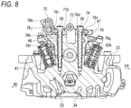
- Fig. 2 is a perspective view of an inside of a cylinder head according to the present embodiment.
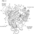
- Fig. 3 is a perspective view of a variable valve device according to the present embodiment.
- an arrow FR indicates a vehicle front side
- an arrow RE indicates a vehicle rear side
- an arrow L indicates a vehicle left side
- an arrow R indicates a vehicle right side.
- a center side in a left-right direction of the cylinder head is referred to as one side
- an outer side in the left-right direction of the cylinder head is referred to as the other side.
- the engine 20 is a parallel two-cylinder engine, and includes a crankcase 21, a cylinder 22 provided on the crankcase 21, a cylinder head 23 provided on the cylinder 22, and a cylinder head cover 24 provided on the cylinder head 23.
- a magnet cover 25 that covers a magnet (not shown) from a lateral side is attached to a left side surface of the crankcase 21.
- a sprocket cover 26 that covers a drive sprocket (not shown) from a lateral side is attached to the rear of the magnet cover 25.
- a clutch cover (not shown) that covers a clutch (not shown) from a lateral side is attached to a right side surface of the crankcase 21.
- the hydraulic piston 63 and the spring pin 64 are separated greatly in a left-right direction.
- the hydraulic piston 63 and the spring pin 64 are arranged as separate members, it is difficult to achieve a parallelism between the hydraulic piston 63 and the spring pin 64, and there is a possibility that components are worn due to partial contact. Therefore, in the variable valve device 40 according to the present embodiment, an upper housing 70 is supported at both ends by upper surfaces of the cam housings 42a and 42b, and the hydraulic piston 63 and the spring pin 64 are arranged on the upper housing 70.
- the first bridge portion 72 extends along the rocker shaft 46 on the intake side (see Fig. 3 ), and a lubricating passage 76k (see Fig. 9 ) through which the lubricating oil passes is formed in the first bridge portion 72.
- a plurality of supply holes 77c are formed in a lower surface of the first bridge portion 72, and the plurality of supply holes 77c are located above contact locations between components.
- a pair of nozzles 78 protrude from the first bridge portion 72 to the intake side, and supply holes 77d at tips of the pair of nozzles 78 are located above the pair of intake valves 33 (see Fig. 10 ).
- the first bridge portion 72 is connected to the housing fixing portions 71a and 71b via connecting portions 81a and 81b.
- a hydraulic chamber (a first accommodation hole) 82 (see Figs. 14A and 14B ) is formed in the connecting portion 81a which is a connecting location between the first bridge portion 72 and the housing fixing portion 71a.
- An accommodation hole (a second accommodation hole) 83 (see Figs. 14A and 14B ) is formed in the connecting portion 81b which is a connecting location between the first bridge portion 72 and the housing fixing portion 71b.
- the hydraulic piston 63 serving as a hydraulic piston is disposed in the hydraulic chamber 82, and the spring pin 64 (see Fig. 9 ) is disposed in the accommodation hole 83.
- the second bridge portion 73 extends along the camshaft 41 (see Fig. 3 ), and a lubricating passage 76n (see Fig. 12 ) is formed in the second bridge portion 73.
- a plurality of supply holes 77e are formed in a lower surface of the second bridge portion 73, and the plurality of supply holes 77e are located above the rocker arms 51a, 51b, and 52.
- the third bridge portion 74 extends along the exhaust rocker shaft 47 on the exhaust side (see Fig. 3 ).
- a pair of nozzles 79 protrude from the third bridge portion 74 to the exhaust side, and supply holes 77f (see Fig. 10 ) at tips of the pair of nozzles 79 are located above the pair of exhaust valves 34 (see Fig. 10 ).
- the lubricating oil is supplied from a supply hole 77a of the rocker shaft 46 to the rocker arms 51a and 51b on the intake side, and the lubricating oil is supplied from a supply hole 77b of the rocker shaft 47 to the rocker arm 52 on the exhaust side.
- the housing fixing portion 71b on the other side is fixed to the cylinder head 23 via the cam housing 42b by using a pair of housing bolts 28.
- a gap between the housing bolt 28 on the intake side and a bolt hole forms a lubricating passage 76h extending from the other end of the lubricating passage 76f of the rocker shaft 46 to the housing fixing portion 71b.
- a lubricating passage 76j extends obliquely from the lubricating passage 76i on a mating surface between the housing fixing portion 71b and the cam housing 42b to the first bridge portion 72.
- the lubricating oil is guided from one end to the other end of the lubricating passage 76f, and the lubricating oil is guided to the lubricating passage 76k in the first bridge portion 72 through the lubricating passages 76h to 76j.
- the lubricating oil is supplied from the plurality of supply holes 77c of the first bridge portion 72 to contact locations of the hydraulic piston 63, the connecting pin 61, the return pin 62, and the spring pin 64. Contact locations between pin components are lubricated to prevent wear.
- the pair of nozzles 78 protrude from the first bridge portion 72 to the intake side, and the supply holes 77d of the pair of nozzles 78 face an inner wall surface of the cylinder head cover 24.
- the short-cut passage 86 extends directly from the oil control valve 16 to the hydraulic piston 63.
- the short-cut passage 86 is formed shorter than the operating passage 85.
- a stepwise oil supply structure with respect to the hydraulic piston 63 is formed such that the oil is supplied from the short-cut passage 86 to the hydraulic piston 63 after the oil is supplied from the operating passage 85 to the hydraulic piston 63.
- the intermittent supply of the oil from the operating passage 85 alone may cause the hydraulic piston 63 to move, the hydraulic piston 63 is stably maintained by directly supplying the oil from the short-cut passage 86.
- variable valve device 40 of the present embodiment when the return pin 62 is pushed to the other side via the connecting pin 61 by the hydraulic piston 63, the connecting pin 61 partially enters the pin hole of the rocker arm 51a from the pin hole of the rocker arm 51b, so that the rocker arms 51a and 51b are connected.
- the connecting pin 61 is pushed back to the one side via the return pin 62 by the spring pin 64, the connecting pin 61 is pulled out from the pin hole of the rocker arm 51a, so that the connection of the rocker arms 51a and 51b is released. In this way, the connected state and a released state of the rocker arms 51a and 51b can be switched with a simple configuration.
- the hydraulic chamber 82 and the accommodation hole 83 are formed in the upper housing 70, a parallelism between the components is easily achieved, and the wear due to the partial contact between the components is prevented.
- the pair of rocker arms are provided on the intake side of the variable valve device, but a plurality of rocker arms may be provided on the intake side of the variable valve device. For example, three or more rocker arms may be provided on the intake side of the variable valve device.
- the hydraulic piston is shown as an example of the pressing member, but the pressing member may be a member that causes the connecting pin to push the return pin to the other side.
- the spring pin is shown as an example of the repulsive member, but the repulsive member may be a member that causes the return pin to push back the connecting pin to the one side.
- the upper housing includes the first to third bridge portions, but the upper housing may be formed in a manner of being supported at both ends by the upper surfaces of the pair of cam housings.
- the operating passage and the short-cut passage are formed in the upper housing, but an oil passage capable of supplying the operating oil to the hydraulic piston may be formed in the cylinder head.
- the connecting pin when the return pin is pushed to the other side via the connecting pin by the pressing member, the connecting pin partially enters from the pin hole of the rocker arm closer to one side into the pin hole of the rocker arm closer to the other side, so that the plurality of rocker arms are connected.
- the connecting pin is pushed back to the one side via the return pin by the repulsive member, the connecting pin is pulled out from the pin hole of the rocker arm closer to the other side, so that the connection of the plurality of rocker arms is released.
- a connected state and a released state of the plurality of rocker arms can be switched with a simple configuration.
- the first accommodation hole and the second accommodation hole are formed in the upper housing, a parallelism between components is easily achieved, and wear due to partial contact between the components is prevented.
- the first bridge portion is formed with a plurality of supply holes (77c) configured to allow a lubricating oil to be supplied to contact locations of the connecting pin, the return pin, the pressing member, and the repulsive member.
- a lubricating oil supplied to contact locations of the connecting pin, the return pin, the pressing member, and the repulsive member.
- the first bridge portion is formed with a supply hole (77d) configured to allow a lubricating oil to be supplied to a stem end of the intake valve. According to this configuration, the stem end of the intake valve can be lubricated.
- the upper housing includes a second bridge portion (73) that is located between the intake side and an exhaust side of the cylinder head and connects the pair of housing fixing portions, and the pair of housing fixing portions are fixed to the pair of cam housings between the first bridge portion and the second bridge portion. According to this configuration, a rigidity of the upper housing can be increased by the second bridge portion. In addition, it is possible to secure bolt tightening locations between the first and second bridge portions and fix the upper housing to the cam housings without increasing a size of the upper housing.
- the third bridge portion is formed with a supply hole (77f) configured to allow a lubricating oil to be supplied to a stem end of the exhaust valve. According to this configuration, the stem end of the exhaust valve can be lubricated.
- the pressing member is a hydraulic piston configured to be operated with a hydraulic pressure
- a mating surface of the pair of cam housings and the pair of housing fixing portions is formed with an oil passage (the operating passage 85, the short-cut passage 86) configured to allow an operating oil to be supplied to the hydraulic piston.
- the oil passage can be formed in a compact manner using the mating surface of the pair of cam housings and the pair of housing fixing portions.
Landscapes
- Engineering & Computer Science (AREA)
- Mechanical Engineering (AREA)
- General Engineering & Computer Science (AREA)
- Valve Device For Special Equipments (AREA)
- Valve-Gear Or Valve Arrangements (AREA)
Claims (9)
- Variable Ventilvorrichtung (40), die in der Lage ist, den Ventilbetrieb eines Einlassventils und eines Auslassventils in einem Zylinderkopf zu ändern, wobei die variable Ventilvorrichtung Folgendes umfasst:ein Paar von Nockengehäusen (42a, 42b), die in einer vorbestimmten Richtung in dem Zylinderkopf getrennt sind;eine Kipphebelwelle (47), die von gegenüberliegenden Abschnitten des Paars von Nockengehäusen getragen wird;eine Vielzahl von Kipphebeln (51a, 51b), die schwenkbar durch die Kipphebelwelle getragen wird;einen Verbindungsstift (61), der in einem Stiftloch eines Kipphebels näher an einer Seite in einer vorbestimmten Richtung angeordnet ist;einen Rückführungsstift (62), der in einem Stiftloch eines Kipphebels näher an der anderen Seite in der vorbestimmten Richtung angeordnet ist;ein Druckglied (63), das dazu ausgelegt ist, den Verbindungsstift zum Schieben des Rückführungsstifts zu der anderen Seite zu veranlassen;ein Abstoßglied (64), das dazu ausgelegt ist, den Rückführungsstift zum Zurückschieben des Verbindungsstifts zu einer Seite zu veranlassen; undein oberes Gehäuse (70), das an beiden Enden durch obere Flächen des Paares von Nockengehäusen getragen wird, wobeidas obere Gehäuse mit einem ersten Aufnahmeloch (82), in dem das Druckglied auf einer Seite in Bezug auf den Kipphebel näher an einer Seite angeordnet ist, und einem zweiten Aufnahmeloch (83) ausgebildet ist, in dem das Abstoßglied auf der anderen Seite in Bezug auf den Kipphebel näher an der anderen Seite angeordnet ist.
- Variable Ventilvorrichtung nach Anspruch 1, wobeidas obere Gehäuse ein Paar von Gehäusebefestigungsabschnitten, die an dem Paar von Nockengehäusen befestigt sind, und einen ersten Brückenabschnitt beinhaltet, der sich auf einer Einlassseite des Zylinderkopfs befindet und das Paar von Gehäusebefestigungsabschnitten verbindet, unddas erste Aufnahmeloch an einer Verbindungsstelle zwischen einem Gehäusebefestigungsabschnitt und dem ersten Brückenabschnitt ausgebildet ist, und das zweite Aufnahmeloch an einer Verbindungsstelle zwischen dem anderen Gehäusebefestigungsabschnitt und dem ersten Brückenabschnitt ausgebildet ist.
- Variable Ventilvorrichtung nach Anspruch 2, wobei
der erste Brückenabschnitt mit einer Vielzahl von Zufuhrlöchern ausgebildet ist, die dazu ausgelegt sind, das Zuführen eines Schmieröls zu Kontaktstellen des Verbindungsstifts, des Rückführungsstifts, des Druckglieds und des Abstoßglieds zu ermöglichen. - Variable Ventilvorrichtung nach Anspruch 2 oder 3, wobei
der erste Brückenabschnitt mit einem Zufuhrloch ausgebildet ist, das dazu ausgelegt ist, das Zuführen eines Schmieröls zu einem Schaftende des Einlassventils zu ermöglichen. - Variable Ventilvorrichtung nach Anspruch 2, wobeidas obere Gehäuse einen zweiten Brückenabschnitt beinhaltet, der sich zwischen der Einlassseite und einer Auslassseite des Zylinderkopfs befindet und das Paar von Gehäusebefestigungsabschnitten verbindet, unddas Paar von Gehäusebefestigungsabschnitten an dem Paar von Nockengehäusen zwischen dem ersten Brückenabschnitt und dem zweiten Brückenabschnitt befestigt ist.
- Variable Ventilvorrichtung nach Anspruch 5, wobei der zweite Brückenabschnitt mit einer Vielzahl von Zufuhrlöchern ausgebildet ist, die dazu ausgelegt sind, das Zuführen eines Schmieröls zu einer Vielzahl von Kipphebeln zu ermöglichen.
- Variable Ventilvorrichtung nach Anspruch 2 oder 3, wobeidas obere Gehäuse einen dritten Brückenabschnitt beinhaltet, der sich auf einer Auslassseite des Zylinderkopfs befindet und das Paar von Gehäusebefestigungsabschnitten verbindet, unddas Paar von Gehäusebefestigungsabschnitten an dem Paar von Nockengehäusen an beiden Enden des dritten Brückenabschnitts befestigt ist.
- Variable Ventilvorrichtung nach Anspruch 7, wobei
der dritte Brückenabschnitt mit einem Zufuhrloch ausgebildet ist, das dazu ausgelegt ist, das Zuführen eines Schmieröls zu einem Schaftende des Auslassventils zu ermöglichen. - Variable Ventilvorrichtung nach Anspruch 2 oder 3, wobeidas Druckglied ein hydraulischer Kolben ist, der dazu ausgelegt ist, mit einem hydraulischen Druck betrieben zu werden, undeine Passfläche des Paars von Nockengehäusen und des Paars von Gehäusebefestigungsabschnitten mit einem Öldurchgang ausgebildet ist, der dazu ausgelegt ist, das Zuführen eines Betriebsöls zu dem Hydraulikkolben zu ermöglichen.
Applications Claiming Priority (1)
| Application Number | Priority Date | Filing Date | Title |
|---|---|---|---|
| JP2022141432A JP2024036892A (ja) | 2022-09-06 | 2022-09-06 | 可変動弁装置 |
Publications (2)
| Publication Number | Publication Date |
|---|---|
| EP4336020A1 EP4336020A1 (de) | 2024-03-13 |
| EP4336020B1 true EP4336020B1 (de) | 2025-07-02 |
Family
ID=87929252
Family Applications (1)
| Application Number | Title | Priority Date | Filing Date |
|---|---|---|---|
| EP23194977.7A Active EP4336020B1 (de) | 2022-09-06 | 2023-09-01 | Variable ventilvorrichtung |
Country Status (3)
| Country | Link |
|---|---|
| US (1) | US12221910B2 (de) |
| EP (1) | EP4336020B1 (de) |
| JP (1) | JP2024036892A (de) |
Family Cites Families (9)
| Publication number | Priority date | Publication date | Assignee | Title |
|---|---|---|---|---|
| JP3378737B2 (ja) * | 1996-06-28 | 2003-02-17 | 株式会社オティックス | 可変動弁機構 |
| JPH10103035A (ja) * | 1996-09-24 | 1998-04-21 | Toyota Motor Corp | 内燃機関のオイル供給装置 |
| JP4212971B2 (ja) * | 2003-06-30 | 2009-01-21 | 株式会社オティックス | 可変動弁機構 |
| JP4931758B2 (ja) * | 2007-10-05 | 2012-05-16 | 株式会社オティックス | 可変動弁機構 |
| JP5907552B2 (ja) | 2010-09-07 | 2016-04-26 | 本田技研工業株式会社 | 内燃機関の可変動弁装置 |
| ES2553217T3 (es) * | 2013-03-25 | 2015-12-07 | Honda Motor Co., Ltd. | Aparato de válvula variable para motor de combustión interna de tipo OHC |
| ES2572254T3 (es) * | 2013-09-30 | 2016-05-31 | Honda Motor Co Ltd | Engranaje de válvula variable de motor de combustión interna para vehículo del tipo de montar a horcajadas |
| JP2018197498A (ja) * | 2015-10-15 | 2018-12-13 | ヤマハ発動機株式会社 | 鞍乗型車両用エンジン |
| JP2024037243A (ja) * | 2022-09-07 | 2024-03-19 | スズキ株式会社 | 可変動弁装置 |
-
2022
- 2022-09-06 JP JP2022141432A patent/JP2024036892A/ja active Pending
-
2023
- 2023-09-01 EP EP23194977.7A patent/EP4336020B1/de active Active
- 2023-09-01 US US18/460,176 patent/US12221910B2/en active Active
Also Published As
| Publication number | Publication date |
|---|---|
| US12221910B2 (en) | 2025-02-11 |
| JP2024036892A (ja) | 2024-03-18 |
| EP4336020A1 (de) | 2024-03-13 |
| US20240077003A1 (en) | 2024-03-07 |
Similar Documents
| Publication | Publication Date | Title |
|---|---|---|
| JP4054041B2 (ja) | ローラ・ロッカアームを有する動弁装置、4サイクルエンジンおよび4サイクルエンジンを搭載した自動二輪車 | |
| JP5378091B2 (ja) | 内燃機関の動弁系回転軸の固定構造 | |
| JP6069766B2 (ja) | 内燃機関の可変動弁装置 | |
| US6644262B2 (en) | Oil pump mounting structure for engine | |
| EP4336019A1 (de) | Variable ventilvorrichtung | |
| EP4336020B1 (de) | Variable ventilvorrichtung | |
| JP2001227317A (ja) | 4サイクルエンジンの潤滑装置 | |
| US8051816B2 (en) | V-type engine for vehicle | |
| CN106062326A (zh) | 气门装置的润滑结构 | |
| JP2010071128A (ja) | 4サイクル空油冷エンジン | |
| US7891328B2 (en) | Lubricating system for valve operating system | |
| US6634330B2 (en) | Valve system for engine | |
| EP3222827B1 (de) | Verbrennungsmotor | |
| JP5329354B2 (ja) | 内燃機関 | |
| JP5315166B2 (ja) | エンジンにおける給油構造 | |
| US20250179948A1 (en) | Variable valve device | |
| JP4498990B2 (ja) | 内燃機関の2次エアー供給装置 | |
| JP7447762B2 (ja) | 動力伝達機構の潤滑構造 | |
| KR101219339B1 (ko) | 차량용 실린더 정지장치 | |
| KR100511758B1 (ko) | 오버헤드 밸브 엔진 | |
| JP2024021974A (ja) | 内燃機関の油路構造 | |
| JP2005248929A (ja) | 動弁装置の潤滑構造 | |
| JP2013139719A (ja) | エンジンの動弁系潤滑装置 | |
| JP2010127104A (ja) | 可変動弁装置とこれを備えたエンジン装置および輸送機器 | |
| JP2014084856A (ja) | エンジンのシリンダヘッド構造 |
Legal Events
| Date | Code | Title | Description |
|---|---|---|---|
| PUAI | Public reference made under article 153(3) epc to a published international application that has entered the european phase |
Free format text: ORIGINAL CODE: 0009012 |
|
| STAA | Information on the status of an ep patent application or granted ep patent |
Free format text: STATUS: REQUEST FOR EXAMINATION WAS MADE |
|
| 17P | Request for examination filed |
Effective date: 20231001 |
|
| AK | Designated contracting states |
Kind code of ref document: A1 Designated state(s): AL AT BE BG CH CY CZ DE DK EE ES FI FR GB GR HR HU IE IS IT LI LT LU LV MC ME MK MT NL NO PL PT RO RS SE SI SK SM TR |
|
| GRAP | Despatch of communication of intention to grant a patent |
Free format text: ORIGINAL CODE: EPIDOSNIGR1 |
|
| STAA | Information on the status of an ep patent application or granted ep patent |
Free format text: STATUS: GRANT OF PATENT IS INTENDED |
|
| RIC1 | Information provided on ipc code assigned before grant |
Ipc: F01L 1/053 20060101ALI20250128BHEP Ipc: F01L 13/00 20060101ALI20250128BHEP Ipc: F01L 1/26 20060101ALI20250128BHEP Ipc: F01L 1/24 20060101ALI20250128BHEP Ipc: F01L 1/18 20060101AFI20250128BHEP |
|
| INTG | Intention to grant announced |
Effective date: 20250206 |
|
| GRAS | Grant fee paid |
Free format text: ORIGINAL CODE: EPIDOSNIGR3 |
|
| GRAA | (expected) grant |
Free format text: ORIGINAL CODE: 0009210 |
|
| STAA | Information on the status of an ep patent application or granted ep patent |
Free format text: STATUS: THE PATENT HAS BEEN GRANTED |
|
| AK | Designated contracting states |
Kind code of ref document: B1 Designated state(s): AL AT BE BG CH CY CZ DE DK EE ES FI FR GB GR HR HU IE IS IT LI LT LU LV MC ME MK MT NL NO PL PT RO RS SE SI SK SM TR |
|
| REG | Reference to a national code |
Ref country code: GB Ref legal event code: FG4D |
|
| REG | Reference to a national code |
Ref country code: CH Ref legal event code: EP |
|
| REG | Reference to a national code |
Ref country code: DE Ref legal event code: R096 Ref document number: 602023004475 Country of ref document: DE |
|
| REG | Reference to a national code |
Ref country code: IE Ref legal event code: FG4D |
|
| PGFP | Annual fee paid to national office [announced via postgrant information from national office to epo] |
Ref country code: DE Payment date: 20250813 Year of fee payment: 3 |
|
| PGFP | Annual fee paid to national office [announced via postgrant information from national office to epo] |
Ref country code: AT Payment date: 20251020 Year of fee payment: 3 |
|
| REG | Reference to a national code |
Ref country code: NL Ref legal event code: MP Effective date: 20250702 |
|
| PG25 | Lapsed in a contracting state [announced via postgrant information from national office to epo] |
Ref country code: PT Free format text: LAPSE BECAUSE OF FAILURE TO SUBMIT A TRANSLATION OF THE DESCRIPTION OR TO PAY THE FEE WITHIN THE PRESCRIBED TIME-LIMIT Effective date: 20251103 |
|
| PG25 | Lapsed in a contracting state [announced via postgrant information from national office to epo] |
Ref country code: NL Free format text: LAPSE BECAUSE OF FAILURE TO SUBMIT A TRANSLATION OF THE DESCRIPTION OR TO PAY THE FEE WITHIN THE PRESCRIBED TIME-LIMIT Effective date: 20250702 |
|
| REG | Reference to a national code |
Ref country code: AT Ref legal event code: MK05 Ref document number: 1809451 Country of ref document: AT Kind code of ref document: T Effective date: 20250702 |
|
| PG25 | Lapsed in a contracting state [announced via postgrant information from national office to epo] |
Ref country code: IS Free format text: LAPSE BECAUSE OF FAILURE TO SUBMIT A TRANSLATION OF THE DESCRIPTION OR TO PAY THE FEE WITHIN THE PRESCRIBED TIME-LIMIT Effective date: 20251102 |
|
| PG25 | Lapsed in a contracting state [announced via postgrant information from national office to epo] |
Ref country code: NO Free format text: LAPSE BECAUSE OF FAILURE TO SUBMIT A TRANSLATION OF THE DESCRIPTION OR TO PAY THE FEE WITHIN THE PRESCRIBED TIME-LIMIT Effective date: 20251002 |
|
| REG | Reference to a national code |
Ref country code: LT Ref legal event code: MG9D |
|
| PG25 | Lapsed in a contracting state [announced via postgrant information from national office to epo] |
Ref country code: AT Free format text: LAPSE BECAUSE OF FAILURE TO SUBMIT A TRANSLATION OF THE DESCRIPTION OR TO PAY THE FEE WITHIN THE PRESCRIBED TIME-LIMIT Effective date: 20250702 |
|
| PG25 | Lapsed in a contracting state [announced via postgrant information from national office to epo] |
Ref country code: FI Free format text: LAPSE BECAUSE OF FAILURE TO SUBMIT A TRANSLATION OF THE DESCRIPTION OR TO PAY THE FEE WITHIN THE PRESCRIBED TIME-LIMIT Effective date: 20250702 |
|
| PGFP | Annual fee paid to national office [announced via postgrant information from national office to epo] |
Ref country code: IT Payment date: 20250930 Year of fee payment: 3 |
|
| PG25 | Lapsed in a contracting state [announced via postgrant information from national office to epo] |
Ref country code: HR Free format text: LAPSE BECAUSE OF FAILURE TO SUBMIT A TRANSLATION OF THE DESCRIPTION OR TO PAY THE FEE WITHIN THE PRESCRIBED TIME-LIMIT Effective date: 20250702 |
|
| PG25 | Lapsed in a contracting state [announced via postgrant information from national office to epo] |
Ref country code: GR Free format text: LAPSE BECAUSE OF FAILURE TO SUBMIT A TRANSLATION OF THE DESCRIPTION OR TO PAY THE FEE WITHIN THE PRESCRIBED TIME-LIMIT Effective date: 20251003 |
|
| PG25 | Lapsed in a contracting state [announced via postgrant information from national office to epo] |
Ref country code: CZ Free format text: LAPSE BECAUSE OF FAILURE TO SUBMIT A TRANSLATION OF THE DESCRIPTION OR TO PAY THE FEE WITHIN THE PRESCRIBED TIME-LIMIT Effective date: 20250702 Ref country code: SE Free format text: LAPSE BECAUSE OF FAILURE TO SUBMIT A TRANSLATION OF THE DESCRIPTION OR TO PAY THE FEE WITHIN THE PRESCRIBED TIME-LIMIT Effective date: 20250702 |
|
| PG25 | Lapsed in a contracting state [announced via postgrant information from national office to epo] |
Ref country code: LV Free format text: LAPSE BECAUSE OF FAILURE TO SUBMIT A TRANSLATION OF THE DESCRIPTION OR TO PAY THE FEE WITHIN THE PRESCRIBED TIME-LIMIT Effective date: 20250702 |
|
| PG25 | Lapsed in a contracting state [announced via postgrant information from national office to epo] |
Ref country code: BG Free format text: LAPSE BECAUSE OF FAILURE TO SUBMIT A TRANSLATION OF THE DESCRIPTION OR TO PAY THE FEE WITHIN THE PRESCRIBED TIME-LIMIT Effective date: 20250702 Ref country code: PL Free format text: LAPSE BECAUSE OF FAILURE TO SUBMIT A TRANSLATION OF THE DESCRIPTION OR TO PAY THE FEE WITHIN THE PRESCRIBED TIME-LIMIT Effective date: 20250702 |
|
| PG25 | Lapsed in a contracting state [announced via postgrant information from national office to epo] |
Ref country code: RS Free format text: LAPSE BECAUSE OF FAILURE TO SUBMIT A TRANSLATION OF THE DESCRIPTION OR TO PAY THE FEE WITHIN THE PRESCRIBED TIME-LIMIT Effective date: 20251002 |
|
| PG25 | Lapsed in a contracting state [announced via postgrant information from national office to epo] |
Ref country code: ES Free format text: LAPSE BECAUSE OF FAILURE TO SUBMIT A TRANSLATION OF THE DESCRIPTION OR TO PAY THE FEE WITHIN THE PRESCRIBED TIME-LIMIT Effective date: 20250702 |