EP4336007B1 - Beschlag für eine schiebetür sowie schiebetür - Google Patents
Beschlag für eine schiebetür sowie schiebetür Download PDFInfo
- Publication number
- EP4336007B1 EP4336007B1 EP23190641.3A EP23190641A EP4336007B1 EP 4336007 B1 EP4336007 B1 EP 4336007B1 EP 23190641 A EP23190641 A EP 23190641A EP 4336007 B1 EP4336007 B1 EP 4336007B1
- Authority
- EP
- European Patent Office
- Prior art keywords
- fitting
- sliding
- guide
- fitting unit
- door
- Prior art date
- Legal status (The legal status is an assumption and is not a legal conclusion. Google has not performed a legal analysis and makes no representation as to the accuracy of the status listed.)
- Active
Links
Images

Classifications
-
- E—FIXED CONSTRUCTIONS
- E05—LOCKS; KEYS; WINDOW OR DOOR FITTINGS; SAFES
- E05D—HINGES OR SUSPENSION DEVICES FOR DOORS, WINDOWS OR WINGS
- E05D15/00—Suspension arrangements for wings
- E05D15/06—Suspension arrangements for wings for wings sliding horizontally more or less in their own plane
- E05D15/0621—Details, e.g. suspension or supporting guides
- E05D15/0626—Details, e.g. suspension or supporting guides for wings suspended at the top
- E05D15/0656—Bottom guides
-
- E—FIXED CONSTRUCTIONS
- E05—LOCKS; KEYS; WINDOW OR DOOR FITTINGS; SAFES
- E05D—HINGES OR SUSPENSION DEVICES FOR DOORS, WINDOWS OR WINGS
- E05D15/00—Suspension arrangements for wings
- E05D15/06—Suspension arrangements for wings for wings sliding horizontally more or less in their own plane
- E05D15/0604—Suspension arrangements for wings for wings sliding horizontally more or less in their own plane allowing an additional movement
-
- E—FIXED CONSTRUCTIONS
- E05—LOCKS; KEYS; WINDOW OR DOOR FITTINGS; SAFES
- E05D—HINGES OR SUSPENSION DEVICES FOR DOORS, WINDOWS OR WINGS
- E05D15/00—Suspension arrangements for wings
- E05D15/06—Suspension arrangements for wings for wings sliding horizontally more or less in their own plane
- E05D15/0621—Details, e.g. suspension or supporting guides
-
- E—FIXED CONSTRUCTIONS
- E05—LOCKS; KEYS; WINDOW OR DOOR FITTINGS; SAFES
- E05D—HINGES OR SUSPENSION DEVICES FOR DOORS, WINDOWS OR WINGS
- E05D15/00—Suspension arrangements for wings
- E05D15/48—Suspension arrangements for wings allowing alternative movements
-
- E—FIXED CONSTRUCTIONS
- E05—LOCKS; KEYS; WINDOW OR DOOR FITTINGS; SAFES
- E05D—HINGES OR SUSPENSION DEVICES FOR DOORS, WINDOWS OR WINGS
- E05D15/00—Suspension arrangements for wings
- E05D15/56—Suspension arrangements for wings with successive different movements
- E05D15/58—Suspension arrangements for wings with successive different movements with both swinging and sliding movements
-
- E—FIXED CONSTRUCTIONS
- E05—LOCKS; KEYS; WINDOW OR DOOR FITTINGS; SAFES
- E05D—HINGES OR SUSPENSION DEVICES FOR DOORS, WINDOWS OR WINGS
- E05D15/00—Suspension arrangements for wings
- E05D15/48—Suspension arrangements for wings allowing alternative movements
- E05D2015/482—Suspension arrangements for wings allowing alternative movements for panic doors
-
- E—FIXED CONSTRUCTIONS
- E05—LOCKS; KEYS; WINDOW OR DOOR FITTINGS; SAFES
- E05D—HINGES OR SUSPENSION DEVICES FOR DOORS, WINDOWS OR WINGS
- E05D15/00—Suspension arrangements for wings
- E05D15/56—Suspension arrangements for wings with successive different movements
- E05D15/58—Suspension arrangements for wings with successive different movements with both swinging and sliding movements
- E05D2015/586—Suspension arrangements for wings with successive different movements with both swinging and sliding movements with travelling hinge parts
-
- E—FIXED CONSTRUCTIONS
- E05—LOCKS; KEYS; WINDOW OR DOOR FITTINGS; SAFES
- E05Y—INDEXING SCHEME ASSOCIATED WITH SUBCLASSES E05D AND E05F, RELATING TO CONSTRUCTION ELEMENTS, ELECTRIC CONTROL, POWER SUPPLY, POWER SIGNAL OR TRANSMISSION, USER INTERFACES, MOUNTING OR COUPLING, DETAILS, ACCESSORIES, AUXILIARY OPERATIONS NOT OTHERWISE PROVIDED FOR, APPLICATION THEREOF
- E05Y2201/00—Constructional elements; Accessories therefor
- E05Y2201/20—Brakes; Disengaging means; Holders; Stops; Valves; Accessories therefor
- E05Y2201/224—Stops
-
- E—FIXED CONSTRUCTIONS
- E05—LOCKS; KEYS; WINDOW OR DOOR FITTINGS; SAFES
- E05Y—INDEXING SCHEME ASSOCIATED WITH SUBCLASSES E05D AND E05F, RELATING TO CONSTRUCTION ELEMENTS, ELECTRIC CONTROL, POWER SUPPLY, POWER SIGNAL OR TRANSMISSION, USER INTERFACES, MOUNTING OR COUPLING, DETAILS, ACCESSORIES, AUXILIARY OPERATIONS NOT OTHERWISE PROVIDED FOR, APPLICATION THEREOF
- E05Y2201/00—Constructional elements; Accessories therefor
- E05Y2201/60—Suspension or transmission members; Accessories therefor
- E05Y2201/606—Accessories therefor
- E05Y2201/62—Synchronisation of suspension or transmission members
-
- E—FIXED CONSTRUCTIONS
- E05—LOCKS; KEYS; WINDOW OR DOOR FITTINGS; SAFES
- E05Y—INDEXING SCHEME ASSOCIATED WITH SUBCLASSES E05D AND E05F, RELATING TO CONSTRUCTION ELEMENTS, ELECTRIC CONTROL, POWER SUPPLY, POWER SIGNAL OR TRANSMISSION, USER INTERFACES, MOUNTING OR COUPLING, DETAILS, ACCESSORIES, AUXILIARY OPERATIONS NOT OTHERWISE PROVIDED FOR, APPLICATION THEREOF
- E05Y2201/00—Constructional elements; Accessories therefor
- E05Y2201/60—Suspension or transmission members; Accessories therefor
- E05Y2201/622—Suspension or transmission members elements
- E05Y2201/64—Carriers
-
- E—FIXED CONSTRUCTIONS
- E05—LOCKS; KEYS; WINDOW OR DOOR FITTINGS; SAFES
- E05Y—INDEXING SCHEME ASSOCIATED WITH SUBCLASSES E05D AND E05F, RELATING TO CONSTRUCTION ELEMENTS, ELECTRIC CONTROL, POWER SUPPLY, POWER SIGNAL OR TRANSMISSION, USER INTERFACES, MOUNTING OR COUPLING, DETAILS, ACCESSORIES, AUXILIARY OPERATIONS NOT OTHERWISE PROVIDED FOR, APPLICATION THEREOF
- E05Y2201/00—Constructional elements; Accessories therefor
- E05Y2201/60—Suspension or transmission members; Accessories therefor
- E05Y2201/622—Suspension or transmission members elements
- E05Y2201/644—Flexible elongated pulling elements
- E05Y2201/654—Cables
-
- E—FIXED CONSTRUCTIONS
- E05—LOCKS; KEYS; WINDOW OR DOOR FITTINGS; SAFES
- E05Y—INDEXING SCHEME ASSOCIATED WITH SUBCLASSES E05D AND E05F, RELATING TO CONSTRUCTION ELEMENTS, ELECTRIC CONTROL, POWER SUPPLY, POWER SIGNAL OR TRANSMISSION, USER INTERFACES, MOUNTING OR COUPLING, DETAILS, ACCESSORIES, AUXILIARY OPERATIONS NOT OTHERWISE PROVIDED FOR, APPLICATION THEREOF
- E05Y2201/00—Constructional elements; Accessories therefor
- E05Y2201/60—Suspension or transmission members; Accessories therefor
- E05Y2201/622—Suspension or transmission members elements
- E05Y2201/658—Members cooperating with flexible elongated pulling elements
- E05Y2201/66—Deflectors; Guides
-
- E—FIXED CONSTRUCTIONS
- E05—LOCKS; KEYS; WINDOW OR DOOR FITTINGS; SAFES
- E05Y—INDEXING SCHEME ASSOCIATED WITH SUBCLASSES E05D AND E05F, RELATING TO CONSTRUCTION ELEMENTS, ELECTRIC CONTROL, POWER SUPPLY, POWER SIGNAL OR TRANSMISSION, USER INTERFACES, MOUNTING OR COUPLING, DETAILS, ACCESSORIES, AUXILIARY OPERATIONS NOT OTHERWISE PROVIDED FOR, APPLICATION THEREOF
- E05Y2201/00—Constructional elements; Accessories therefor
- E05Y2201/60—Suspension or transmission members; Accessories therefor
- E05Y2201/622—Suspension or transmission members elements
- E05Y2201/658—Members cooperating with flexible elongated pulling elements
- E05Y2201/668—Pulleys; Wheels
-
- E—FIXED CONSTRUCTIONS
- E05—LOCKS; KEYS; WINDOW OR DOOR FITTINGS; SAFES
- E05Y—INDEXING SCHEME ASSOCIATED WITH SUBCLASSES E05D AND E05F, RELATING TO CONSTRUCTION ELEMENTS, ELECTRIC CONTROL, POWER SUPPLY, POWER SIGNAL OR TRANSMISSION, USER INTERFACES, MOUNTING OR COUPLING, DETAILS, ACCESSORIES, AUXILIARY OPERATIONS NOT OTHERWISE PROVIDED FOR, APPLICATION THEREOF
- E05Y2201/00—Constructional elements; Accessories therefor
- E05Y2201/60—Suspension or transmission members; Accessories therefor
- E05Y2201/622—Suspension or transmission members elements
- E05Y2201/684—Rails; Tracks
-
- E—FIXED CONSTRUCTIONS
- E05—LOCKS; KEYS; WINDOW OR DOOR FITTINGS; SAFES
- E05Y—INDEXING SCHEME ASSOCIATED WITH SUBCLASSES E05D AND E05F, RELATING TO CONSTRUCTION ELEMENTS, ELECTRIC CONTROL, POWER SUPPLY, POWER SIGNAL OR TRANSMISSION, USER INTERFACES, MOUNTING OR COUPLING, DETAILS, ACCESSORIES, AUXILIARY OPERATIONS NOT OTHERWISE PROVIDED FOR, APPLICATION THEREOF
- E05Y2201/00—Constructional elements; Accessories therefor
- E05Y2201/60—Suspension or transmission members; Accessories therefor
- E05Y2201/622—Suspension or transmission members elements
- E05Y2201/696—Screw mechanisms
-
- E—FIXED CONSTRUCTIONS
- E05—LOCKS; KEYS; WINDOW OR DOOR FITTINGS; SAFES
- E05Y—INDEXING SCHEME ASSOCIATED WITH SUBCLASSES E05D AND E05F, RELATING TO CONSTRUCTION ELEMENTS, ELECTRIC CONTROL, POWER SUPPLY, POWER SIGNAL OR TRANSMISSION, USER INTERFACES, MOUNTING OR COUPLING, DETAILS, ACCESSORIES, AUXILIARY OPERATIONS NOT OTHERWISE PROVIDED FOR, APPLICATION THEREOF
- E05Y2201/00—Constructional elements; Accessories therefor
- E05Y2201/60—Suspension or transmission members; Accessories therefor
- E05Y2201/622—Suspension or transmission members elements
- E05Y2201/71—Toothed gearing
- E05Y2201/712—Toothed gearing with incomplete toothing
-
- E—FIXED CONSTRUCTIONS
- E05—LOCKS; KEYS; WINDOW OR DOOR FITTINGS; SAFES
- E05Y—INDEXING SCHEME ASSOCIATED WITH SUBCLASSES E05D AND E05F, RELATING TO CONSTRUCTION ELEMENTS, ELECTRIC CONTROL, POWER SUPPLY, POWER SIGNAL OR TRANSMISSION, USER INTERFACES, MOUNTING OR COUPLING, DETAILS, ACCESSORIES, AUXILIARY OPERATIONS NOT OTHERWISE PROVIDED FOR, APPLICATION THEREOF
- E05Y2201/00—Constructional elements; Accessories therefor
- E05Y2201/60—Suspension or transmission members; Accessories therefor
- E05Y2201/622—Suspension or transmission members elements
- E05Y2201/71—Toothed gearing
- E05Y2201/716—Pinions
-
- E—FIXED CONSTRUCTIONS
- E05—LOCKS; KEYS; WINDOW OR DOOR FITTINGS; SAFES
- E05Y—INDEXING SCHEME ASSOCIATED WITH SUBCLASSES E05D AND E05F, RELATING TO CONSTRUCTION ELEMENTS, ELECTRIC CONTROL, POWER SUPPLY, POWER SIGNAL OR TRANSMISSION, USER INTERFACES, MOUNTING OR COUPLING, DETAILS, ACCESSORIES, AUXILIARY OPERATIONS NOT OTHERWISE PROVIDED FOR, APPLICATION THEREOF
- E05Y2201/00—Constructional elements; Accessories therefor
- E05Y2201/60—Suspension or transmission members; Accessories therefor
- E05Y2201/622—Suspension or transmission members elements
- E05Y2201/71—Toothed gearing
- E05Y2201/722—Racks
-
- E—FIXED CONSTRUCTIONS
- E05—LOCKS; KEYS; WINDOW OR DOOR FITTINGS; SAFES
- E05Y—INDEXING SCHEME ASSOCIATED WITH SUBCLASSES E05D AND E05F, RELATING TO CONSTRUCTION ELEMENTS, ELECTRIC CONTROL, POWER SUPPLY, POWER SIGNAL OR TRANSMISSION, USER INTERFACES, MOUNTING OR COUPLING, DETAILS, ACCESSORIES, AUXILIARY OPERATIONS NOT OTHERWISE PROVIDED FOR, APPLICATION THEREOF
- E05Y2800/00—Details, accessories and auxiliary operations not otherwise provided for
- E05Y2800/20—Combinations of elements
- E05Y2800/21—Combinations of elements of identical elements, e.g. of identical compression springs
-
- E—FIXED CONSTRUCTIONS
- E05—LOCKS; KEYS; WINDOW OR DOOR FITTINGS; SAFES
- E05Y—INDEXING SCHEME ASSOCIATED WITH SUBCLASSES E05D AND E05F, RELATING TO CONSTRUCTION ELEMENTS, ELECTRIC CONTROL, POWER SUPPLY, POWER SIGNAL OR TRANSMISSION, USER INTERFACES, MOUNTING OR COUPLING, DETAILS, ACCESSORIES, AUXILIARY OPERATIONS NOT OTHERWISE PROVIDED FOR, APPLICATION THEREOF
- E05Y2900/00—Application of doors, windows, wings or fittings thereof
- E05Y2900/10—Application of doors, windows, wings or fittings thereof for buildings or parts thereof
- E05Y2900/13—Type of wing
- E05Y2900/132—Doors
Definitions
- the invention relates to a fitting for a sliding door with breakout functionality, comprising an upper fitting unit guided in a ceiling guide of the fitting and a lower fitting unit guided in a floor guide of the fitting for guiding a door leaf of the sliding door during normal operation along a first sliding direction and a second sliding direction opposite thereto, wherein the fitting units enable the door leaf of the sliding door to be pivoted open about an axis of rotation defined by the fitting units in the event of a breakout, according to the preamble of claim 1. Furthermore, the invention relates to a sliding door with breakout functionality, comprising a fitting for a sliding door and at least one door leaf which is displaceably mounted by the fitting during normal operation along a first sliding direction and a second sliding direction opposite thereto.
- Sliding doors with breakout functionality and fittings for such sliding doors that enable this breakout functionality are generally well known.
- these doors are used as sliding doors, with one or more door leaves, often motorized, being able to move between a closed and an open position, guided by a ceiling and floor guide.
- the door leaf(s) can also be pivoted around a pivot axis and thus opened like a swing door.
- a known way to circumvent the problem described above is to equip the lower secondary closing edge of the door leaf with a supporting roller. While this can generally prevent tilting, which would hinder or even completely prevent the door leaf from swinging out, it simultaneously creates new requirements for the substructure to ensure that the supporting roller does not also tilt, thereby hindering or completely preventing the door leaf from swinging out.
- US 2005/183340 A1 discloses a fitting according to the preamble of claim 1.
- This document discloses a brake assembly for locking a vertically or horizontally sliding window or door in the track of a frame.
- the track has an elongated base and a pair of spaced-apart, opposed side walls extending perpendicularly from the base. Each side wall has an internal shoulder spaced from and parallel to the base.
- the assembly includes a sliding body having a central opening extending from a front of the body to a rear of the body.
- the sliding body has a side opening on each side of the sliding body communicating with the central opening.
- a pair of brake elements are provided, with one brake element positioned in a respective one of the side openings.
- a cam having a rear and a front side is adapted to receive a pivot member mounted on the window sash or door.
- the cam is positioned in the central opening and is configured to be rotated within the opening by the pivoting member.
- the cam, sliding body, and braking elements comprise a cooperating structure for converting rotational movement of the cam into radial movement of the braking elements through the side openings and axial movement of the cam and sliding body to lock the braking assembly in the rail.
- DE 10 2012 210 594 A1 discloses a sliding door system with at least one sliding leaf guided displaceably along a guide device.
- the sliding door system can be used in an escape route in which the sliding leaf can be pivoted by manual force application from a basic position located essentially in the plane of the sliding door system and corresponding to normal operation of the sliding door system into at least one escape route position.
- the sliding leaf has a compensation device for preventing the pivoted sliding leaf from lowering towards the main closing edge.
- the compensation device has a flexible force transmission element that connects an upper guide element or a component connected thereto to a lower guide element or a component connected thereto and is guided via at least one stationary deflection element.
- US 2017/009513 A1 discloses locking systems having rollers that run along the top and bottom of individual sliding elements, the rollers being horizontally oriented and arranged in a track designed to receive the horizontal rollers.
- a track leveling system allows installers to more easily install and align the system between floors and cladding that are not perfectly flush.
- a pressure piece allows the system to be closed via sliding elements that press into the piece to deflect it to better seal the closure of the individual sliding elements.
- a hinge mechanism allows the Rotate sliding elements to stack the sliding elements at one end of the system.
- top refers to a sliding door or its components in the installed state.
- a fitting for a sliding door with breakout functionality comprising an upper fitting unit guided in a ceiling guide of the fitting and a lower fitting unit guided in a floor guide of the fitting for guiding a door leaf of the sliding door during normal operation along a first sliding direction and a second sliding direction opposite thereto, wherein the fitting units enable the door leaf of the sliding door to pivot open about an axis of rotation defined by the fitting units in the breakout case.
- the fitting according to the invention has a locking device for positively and/or non-positively locking the lower fitting unit in the floor guide against movement in the first sliding direction and/or the second sliding direction in the breakout case.
- the fitting according to the invention is intended for use in a sliding door and, in particular, enables normal operation for this sliding door, in which a door leaf can be moved between a closed position and an open position along the sliding directions.
- the first sliding direction can be defined, for example, as a movement of the door leaf toward its closed position, i.e., in the closing direction, while the second sliding direction can be defined, correspondingly, as the opposite opening direction.
- the ceiling guide and the floor guide which essentially determine the guidance of the door leaf during normal operation, extend along these sliding directions and are usually linear.
- the upper and lower fitting units of the fitting can be arranged and fastened to an upper or lower end, in particular an edge or a corner area, of the door leaf. They preferably have the necessary fastening elements for this purpose.
- a drive with a motor unit for automatic movement of the door leaf during normal operation is also conceivable, usually arranged on and/or in the ceiling guide and mechanically connected to the upper fitting unit.
- both fitting units are also designed in such a way that the door leaf can be pivoted open in the event of a breakout.
- both fitting units have a bearing device, preferably a pivot bearing, that allows the door leaf to be pivoted out in the event of a breakout.
- the positions of the two fitting units in the ceiling guide or floor guide determine the axis of rotation around which the door leaf is pivoted.
- the door leaf is preferably aligned along the sliding directions, so that, for example, a lower secondary closing edge of the door leaf runs parallel to the sliding directions.
- the two fitting units are arranged on the door leaf such that they oppose each other with respect to the sliding directions.
- the axis of rotation of the door leaf defined by the fitting units for the breakout case is aligned transversely to the sliding directions in this preferred case.
- the position of the upper fitting unit in the ceiling guide is fixed, especially in the case of an automatic sliding door.
- fixing of the upper fitting unit also applies to non-motorized sliding doors, for example in the event of a breakout.
- a locking device is provided in the fitting according to the invention.
- This locking device also makes it possible to fix the position of the lower fitting unit, in particular essentially to the position that the lower fitting unit assumed when the breakout occurred.
- the locking device is designed such that it can positively and/or non-positively lock the lower fitting unit in the floor guide. A movement of the lower fitting unit in the first and/or second sliding direction and thus a tilting of the rotation axis relative to its ideal alignment transverse to the sliding directions can be avoided.
- the locking device locks the lower fitting unit against movements in both the first sliding direction and the second sliding direction.
- the locking device locks the lower fitting unit at least against movement in the sliding direction in which the predominant part of the lower horizontal edge, i.e. the lower secondary closing edge, of the door leaf would move towards the floor guide.
- the locking device locks the lower fitting unit at least against movement in the first sliding direction, i.e., the opening direction.
- the lower secondary closing edge thus remains parallel to the floor guide or simply moves away from it during movement in the closing direction, so that the swinging out of the door leaf is not impeded.
- the fitting according to the invention enables a breakout function for a sliding door with particularly high reliability and operational safety. Since tilting of the door leaf with its main closing edge toward the floor guide is reliably prevented, this can be achieved without having to provide a supporting roller and the associated additional requirements for the installation environment of the sliding door. For example, rough or uneven floor coverings, in particular, such as floor mats, can also be used.
- the fitting according to the invention is characterized in that the locking device has a toothing extending in the floor guide along the sliding directions and a locking element which is rotatably mounted in the lower fitting unit and adapted to the toothing and can be mechanically operatively connected to the door leaf in such a way that pivoting the door leaf in the event of a breakout leads to a rotation of the locking element, whereby the locking element engages in the toothing and thus the lower fitting unit is positively locked in the floor guide.
- the mechanical operative connection between the door leaf and the locking element can be established directly or indirectly via further elements, for example a transmission gear.
- the locking of the lower fitting unit is achieved via a positive connection between the locking element and the toothing. The risk of overpressing the locking mechanism, which is at least theoretically possible with a purely force-locking locking mechanism, can be significantly reduced in this way.
- the toothing preferably has such a large extension along the sliding directions that the entire sliding path of the door leaf is covered. This makes it possible to lock the lower fitting unit at any sliding position of the door leaf in the event of a breakout.
- An adapted design of the toothing and the locking element within the meaning of the invention means, in particular, that the shape of the toothing, in particular its teeth and the locking receptacles located therebetween, and that of the locking element are selected to be opposite. This ensures that a particularly large-area and therefore particularly effective positive connection between these components can be achieved.
- Both the teeth and the locking receptacles are preferably identical across the entire toothing.
- the toothing is preferably selected in such a way, in particular depending on the size of the sliding door or the door leaf, that the two opposing requirements are met as well as possible, namely that it is fine enough so that the positive locking takes place even with slight rotations of the door leaf, for example with rotations of less than 10°, and that, conversely, it is not selected so finely that there would be a risk of the teeth of the toothing shearing off in the event of a breakout.
- the locking element has a locking edge with an angle of 80° to 100°, preferably 90°, for engaging the toothing, wherein a sliding side of the locking element adjoins the locking edge, which is aligned parallel to the sliding directions during normal operation.
- the toothing in particular its recessed locking receptacles, also has a corresponding shape with the same angle.
- a locking edge with an angle between 80° and 100° has proven to be a good compromise to meet the two requirements stated above as well as possible.
- a sliding side which is preferably extends so far that it covers several teeth and locking receptacles of the toothing during normal operation, prevents or at least makes it more difficult for the locking edge to engage in one of the locking receptacles during normal operation.
- the fitting according to the invention can be designed such that the locking element is cuboid-shaped.
- a cuboid shape of the locking element makes it particularly easy to achieve the advantages described in the previous paragraph.
- the edge located on the side of the locking element diagonally opposite the locking edge can also be supported on the floor guide, thus further supporting the locking element from tilting in the entire floor guide. This can assist the locking of the lower fitting unit in the floor guide, thus making it even more secure.
- the toothing comprises a rack and the locking element comprises a pinion matching the rack, wherein a pinion section of the pinion, which faces the rack during normal operation, is provided with a toothless, preferably smooth, sliding side aligned parallel to the sliding directions.
- a pinion within the meaning of the invention is, in particular, a gear, the teeth of which are adapted to the corresponding teeth of the rack. Tests have determined the size "M2" to be particularly suitable for the rack and pinion.
- the sliding side on the pinion section which comprises at least one, preferably two or more of the teeth of the pinion
- an unintentional engagement of the remaining teeth of the pinion with the rack can be prevented or at least made more difficult.
- the design of the locking device with a pinion with a sliding side and a rack enables, in particular, that On the one hand, trouble-free normal operation can take place, but on the other hand, even a slight twist of the door leaf, and thus also of the pinion via the mechanical connection, leads to immediate engagement of the remaining teeth of the pinion in the rack, which ensures immediate locking of the lower fitting unit in the floor guide in the event of a breakout.
- the fitting according to the invention can be provided with the rack and pinion made of plastic, with the sliding side preferably being produced by milling.
- Plastics are easily moldable and, in particular, easily processable materials that can be manufactured on a large industrial scale in a wide variety of shapes and with a wide range of material properties. This makes it particularly easy to manufacture large quantities of appropriately dimensioned and mechanically sufficiently stable racks and pinions made of plastic.
- the sliding side and/or a pinion hub of the pinion forms part of the guide of the door leaf along the sliding directions.
- the sliding side can be so large along the sliding directions that it extends over several of the teeth of the rack.
- the pinion can then slide with its sliding side along the teeth of the rack and thus form part of the guide of the door leaf.
- a pinion hub or axis of the pinion can extend through a guide slot of the floor guide, particularly in the case of a direct mechanical connection between the pinion and the door leaf.
- the pinion hub or axis of the pinion can also be used to Interaction with the edges of the guide slot to form part of the guide of the door leaf.
- the fitting according to the invention can be characterized in that the locking device comprises a cable connection between the upper fitting unit and the lower fitting unit, wherein a cable of the cable connection is guided in such a way that it engages a first side of the upper fitting unit and a second side of the lower fitting unit opposite the first side with respect to the axis of rotation, wherein in the assembled state the axis of rotation divides a lower edge of the door leaf into a larger first edge section and a smaller second edge section, wherein in particular the first edge section is at least twice, preferably at least 10 times larger than the second edge section, and wherein the second side of the lower fitting unit faces the first edge section of the lower edge.
- the cable of which is preferably kept taut, it can be achieved that in the event of a breakout, in which, as described above, the upper fitting unit is fixed in the ceiling guide and the lower fitting unit is also locked in the floor guide, at least against movement in the direction opposite to the second side of the lower fitting unit.
- the inventive arrangement such that the cable is guided along the larger first edge section before engaging the second side of the lower fitting unit, ensures that this larger, longer first edge section is prevented from tilting toward the floor guide. This makes it particularly easy to reliably enable the door leaf to pivot open in the event of a breakout.
- the fitting according to the invention can be further developed in such a way that the cable of the cable connection is a steel cable.
- Steel cables are particularly strong and permanently stable cables. They can transmit high forces, especially with small diameters and thus with low weight. Furthermore, steel cables are stable in length, so that complex tensioning devices in the cable connection are unnecessary, or at least they can be made simpler and smaller.
- the fitting according to the invention can further be characterized in that the cable connection has three deflection pulleys, wherein the cable runs from the upper fitting unit to an upper deflection pulley, from there to a first lower deflection pulley, from there past the lower fitting unit to a second lower deflection pulley, and from there back to the lower fitting unit.
- the cable engages two sides of the upper and lower fitting units opposite one another with respect to the axis of rotation.
- the cable therefore requires a guide that fulfills this requirement.
- a guide with three deflection pulleys can not only fulfill this requirement particularly easily, but it is also possible for the cable to be guided completely around the door leaf without the need for complex additional guides.
- At least one of the deflection pulleys can also be arranged in a frame of the sliding door. Guiding the Rope over the space covered by the door leaf, which could be perceived as disadvantageous, at least in the case of a door leaf made of a transparent material, can be avoided particularly easily in this way.
- the design of the fitting according to the invention described in the previous paragraph can further be developed such that the cable runs from the upper fitting unit parallel to the sliding directions to the upper deflection pulley, from there perpendicular to the sliding directions to the first lower deflection pulley, from there parallel to the sliding directions to the second lower deflection pulley, and from there, deflected by 180°, again parallel to the sliding directions back to the lower fitting unit.
- the cable of the cable connection between the upper fitting unit and the lower fitting unit runs either parallel or perpendicular to the sliding directions. This makes it particularly easy to arrange or guide the cable concealed by elements of the fitting and/or a frame of the sliding door. Since sliding doors predominantly have rectangular elements, in particular door leaves but also adjacent fixed leaves, scaling the cable connection between sliding doors of different sizes can also be simplified.
- the fitting according to the invention can be provided with the floor guide having a Z-shaped first profile and a U-shaped second profile, wherein the two profiles are connected to one another, preferably screwed, in such a way that they form a guide space with a guide slot that is open along the sliding directions, wherein both profiles border the guide slot, and wherein the toothing is arranged on the side of the guide slot in the guide space formed by the first profile, preferably wherein the profiles are designed as sheet metal profiles.
- the floor guide When using a locking device with a toothing, the floor guide must be designed accordingly so that the additional toothing can be arranged in it. It has been found that, in terms of production technology and cost-effectiveness, a floor guide composed of two profiles, in particular sheet metal profiles, is most advantageous.
- this screw connection can also be used to fasten the floor guide.
- the Z-shaped and U-shaped configurations of the two profiles make it particularly easy to create a guide space inside the floor guide, which accommodates not only the toothing but also a section of the lower fitting unit guided by the floor guide, in particular the locking element.
- the remaining open guide slot enables particularly easy guidance of the lower fitting unit during normal operation and, on the other hand, the mechanical connection of the locking element of the locking device to the door leaf.
- the fitting according to the invention can be designed such that the locking device locks the lower fitting unit in the floor guide in a force-locking and/or form-locking manner when the door leaf is rotated by 10° or less, preferably by 5° or less.
- the locking device locks the lower fitting unit in the floor guide in a force-locking and/or form-locking manner when the door leaf is rotated by 10° or less, preferably by 5° or less.
- this can be made possible, for example, by appropriately designing a thread pitch on a setscrew, the angle of a locking edge or the size of a pinion and a rack.
- Another possibility is to use a gear unit in the mechanical connection between the door leaf and the locking device, whereby even a small twist of the door leaf leads to a mechanical response of the locking device that is increased in accordance with the transmission ratio.
- a sliding door with breakout functionality comprising a fitting for a sliding door and at least one door leaf displaceably mounted by the fitting during normal operation along a first sliding direction and a second sliding direction opposite thereto.
- the sliding door according to the invention is characterized in that the fitting is designed according to the first aspect of the invention. All of the advantages described above with regard to a fitting according to the first aspect of the invention can thus also be provided by a sliding door according to the second aspect of the invention, which has the fitting according to the first aspect of the invention.
- a sliding door according to the invention has at least one door leaf, which is displaceably mounted by the fitting according to the invention.
- the sliding door according to the invention is not limited to this, but can also have additional door leaves, which can also be mounted by fittings according to the invention. Fixed leaves, with and/or without breakout functionality, are also possible. can be parts of a sliding door according to the invention.
- a sliding door according to the invention can be used as a building closure, but also as an interior part of a building. Mobile use, for example, on ships or trains, is also conceivable.
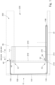
- Fig. 1 shows an embodiment of a sliding door 200, which is equipped with a fitting 10.
- the fitting 10 has an upper fitting unit 40, which is guided in a ceiling guide 36 of the fitting 10. Furthermore, a floor guide 20 and a lower fitting unit 50 are provided as part of the fitting 10, the latter also being guided in the floor guide 20.
- a door leaf 210 of the sliding door 200 is arranged and fastened to the upper and lower fitting units 40, 50, which door leaf is thereby also displaceably mounted, in particular in a first sliding direction 300 and a second sliding direction 400 opposite thereto.
- the first sliding direction 300 corresponds to an opening direction 302
- the second sliding direction 400 corresponds to a closing direction 402 of the sliding door 200.
- a drive 202 is also integrated in the ceiling guide 36, so that the sliding door 200 can also be opened and closed by a drive during normal operation and can therefore take place automatically.
- the sliding door 200 In addition to normal operation, in which the door leaf 210 is moved along the sliding directions 300, 400, the sliding door 200, enabled by the fitting 10, also provides a breakout functionality. If necessary, for example, in the event of a fire alarm or another event that requires a rapid and comprehensive opening of the entire sliding door 200, the door leaf 210 can also be pivoted open like a revolving door. For this pivoting, the two fitting units 40, 50 are designed accordingly, so that a pivot axis 212, around which the door leaf 210 is pivoted, is defined between the two fitting units 40, 50.
- the upper fitting unit 40 is usually already fixed in the event of a breakout, for example, by blocking the drive 202 in the event of a breakout, this is not the case for the lower fitting unit 50 in sliding doors 200 of the prior art.
- a force is applied to the door leaf 210 to pivot it about the pivot axis 212, which usually acts with a large lever arm on a side of the door leaf 210 opposite the pivot axis 212, there is a risk that the still existing The lower fitting unit 50 is tilted in the floor guide 20 of the door leaf 210.
- a force is applied to the door leaf 210 to pivot it about the pivot axis 212, which usually acts with a large lever arm on a side of the door leaf 210 opposite the pivot axis 212, there is a risk that the still existing The lower fitting unit 50 is tilted in the floor guide 20 of the door leaf 210.
- the lower fitting unit 50 would deflect under the action of force, particularly in the first sliding direction 300, and the lower edge 214 of the door leaf 210, in particular the larger first edge section 216 of the two edge sections 216, 218, into which the lower edge 214 is divided by the rotation axis 212, would become wedged relative to the floor guide 20 and/or the floor. Opening of the door leaf 210 could then no longer be ensured, and a breakout functionality of the sliding door 200 would no longer be available.
- the fitting 10 and thus the sliding door 200 has a locking device 12, by which the lower fitting unit 50 is locked against movement in at least one of the sliding directions 300, 400 in the event of a breakout.
- this locking device 12 has, in particular, a cable connection 100, the cable 102 of which is arranged between the fitting units 40, 50.
- the cable 102 engages different sides 42, 52 of the fitting units 40, 50 with respect to the rotation axis 212 of the door leaf 210.
- the side 52 of the lower fitting unit 50 is selected such that it faces the larger first edge portion 216.
- the cable 102 is further guided over three deflection pulleys 104, 106, 108, wherein the cable 102 runs from the upper fitting unit 40 parallel to the sliding directions 300, 400 to the upper deflection pulley 104, from there perpendicular to the sliding directions 300, 400 to the first lower deflection pulley 106, from there parallel to the sliding directions 300, 400 to the second lower deflection pulley 108, and from there, deflected by 180°, again parallel to the sliding directions 300, 400 back to the lower fitting unit 50.
- This arrangement of the cable 102 has the advantage, first and foremost, that the length of the required cable 102 is constant, regardless of the position of the door leaf 210.
- the above-described Fastening of the cable 102 on different sides 42, 52 of the two fitting units 40, 50 can be provided particularly easily, while at the same time concealing the cable 102 behind panels of the fitting 10 or the entire sliding door 200 is easily possible.
- the upper fitting unit 40 When a breakout occurs, as described above, the upper fitting unit 40 is normally locked in the ceiling guide 36. Due to the cable connection 100, the lower fitting unit 50 can therefore automatically no longer move in the first sliding direction 300. This reliably prevents the door leaf 210 from being obstructed or even prevented from pivoting open by tilting the door leaf 210 toward the floor guide 20. In other words, the door leaf 210 is thus guaranteed to pivot open in the event of a breakout.
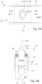
- FIG. 2 Two figures A, B are shown, wherein figure A shows a plan view of a fitting 10, in particular the floor guide 20 and parts of the lower fitting unit 50, in normal operation and figure B shows a side view of this fitting 10 at the beginning of a breakout case.
- the lower fitting unit 50 comprises essential parts of the locking device 12.
- a guide element 60 is mounted in the floor guide 20 along the sliding directions 300, 400. As indicated in Figure B, a movement of the guide element 60 perpendicular to the sliding directions 300, 400, in particular upwards, is also limited by the floor guide 20.
- a threaded pin receptacle 62 is centrally located in the guide element 60. provided, in whose internal thread 64 a matching external thread 74 of a locking element 70, in particular a threaded pin 72, engages. The threaded pin 72 is firmly connected to the door leaf 210 (cf. Fig. 1 ) so that a rotation of the door leaf 210 causes a rotation of the threaded pin 72 in the same direction.
- the door leaf 210 is pivoted about its axis of rotation 212, which in the illustrated case also corresponds to the axis of rotation 212 of the threaded pin 72.
- the threaded pin 72 is also rotated via the mechanical coupling, whereby the threaded pin 72 is extended entirely from the guide element 60 via the threaded connection 64, 74 and clamped against the lower end of the floor guide 20.
- a preferably conical element end 76 supports this clamping, as does a correspondingly designed continuous groove 22 in the floor guide 20.
- the lower fitting unit 50 is locked in the floor guide 20 by the above-described clamping of the threaded pin 72 or, in general, a locking element 70.
- this occurs even at small angles of rotation of the door leaf 210, preferably at angles of rotation less than 10°. In this way, too, the swinging open of the door leaf 210 can be ensured in the event of a breakout, in particular against movement in both sliding directions 300, 400.
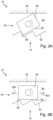
- FIG. 3 An embodiment of a locking device 12 of a fitting 10 according to the invention is shown in Fig. 3 shown.
- FIG. 3 In the upper figure A of the Fig. 3 is a breakout case, in Figure B below a normal operation is shown.
- a toothing 32 is arranged in a guide space 28 of the floor guide 20, wherein the toothing 32 extends along the sliding directions 300, 400.
- the locking device 12, as part of the lower fitting unit 50 has a locking element 80, which is also arranged in the guide space 28 and can preferably be cuboid-shaped, as shown.
- the locking element 80 has, in particular, a locking edge 82, and the toothing 32 is configured correspondingly to the locking edge 82.
- the locking element 80 shown has an angle of 90°; an angle between 80° and 100° is preferred here.
- a sliding side 90 Adjacent to the locking edge 82 is a sliding side 90, which, during normal operation, is aligned along the sliding directions 300, 400, as shown in Figure B. This allows the locking element 80, and thus the entire lower fitting unit 50, not only to be displaced along the sliding directions 300, 400, but also to be guided, for example, by sliding the sliding side 90 along the toothing 32.
- the locking element 80 in the assembled state is connected to the door leaf 210 (cf. Fig. 1 ) mechanically operatively connected, preferably directly or indirectly, for example via a gear unit.
- pivoting of the door leaf 210 leads to a rotation of the locking element 80 in the guide space 28, see Figure A.
- the locking edge 82 then engages in the toothing 32 and in this way positively locks the entire lower fitting unit 50 in the floor rail 20. In the embodiment shown, this is further supported by the edge of the locking element 80, which is diagonally opposite the locking edge 82, striking the inside of the guide space 28.
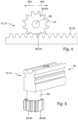
- a toothing 32 and a locking element 80 are also provided, which, as in the Fig. 3 shown embodiment of the locking device 12 according to the invention are formed in the floor guide 20 or as part of the lower fitting unit 50 (cf. Fig. 3 ).
- the locking element 80 is now designed as a pinion 84 and the toothing 32 as a matching rack 34.
- a plastic can be used as the preferred material for both the pinion 84 and the rack 34.
- a locking element 80 which is in normal operation (cf. Fig. 4 ) the pinion section 88 facing the rack 34 is designed as a toothless sliding side 90, which on the one hand enables movement of the pinion 84 and thus of the entire lower fitting unit 50 along the sliding directions 300, 400.
- the sliding side 90 can preferably be created by milling off the pinion section 88 of a complete pinion 84.
- a further part of this guidance can be provided in particular by a pinion hub 86 of the pinion 84, which is arranged in a guide slot 30 (cf. Fig. 6 ) of the floor guide 20.
- Fig. 4 normal operation. If a breakout occurs, the pinion 84, which in the assembled state is connected to the door leaf 210 (cf. Fig. 1 ) is mechanically connected, is also twisted and engages after only a few degrees of twisting, preferably 10° or less, in the toothed rack 34. In this way, the lower fitting unit 50 is locked in the floor guide 20 with only minimal delay, and the door leaf 210 can swing open unhindered.
- Fig. 6 shows a preferred embodiment of a floor guide 20, as it is provided in particular with a locking device 12 in the Fig. 2 to 5 shown embodiments.
- the floor guide 20 has a Z-shaped first profile 24 and a U-shaped second profile 26.
- the profiles 24, 26, which are preferably designed as sheet metal profiles, can in particular be screwed together, wherein the screw connection 38 can also be used to fix the entire floor guide 20. Due to the special shape of the profiles 24, 26, they form a guide space 28 with a guide slot 30 that is open along the sliding directions 300, 400. In this way, sufficient installation space for the toothing 32, which is designed, for example, as a toothed rack 34, can be formed particularly easily.
- the locking element 80 or the pinion 84 can then be arranged in the guide space 28.
- the mechanical operative connection to the door leaf 210 can be made through the guide slot 30, which is arranged at the upper edge of the guide space 28 and is formed jointly by both profiles 24, 26, for example by a pinion hub 86, which is additionally guided by the guide slot 30.
Landscapes
- Engineering & Computer Science (AREA)
- Mechanical Engineering (AREA)
- Support Devices For Sliding Doors (AREA)
- Hinges (AREA)
Applications Claiming Priority (1)
| Application Number | Priority Date | Filing Date | Title |
|---|---|---|---|
| DE102022209510.3A DE102022209510A1 (de) | 2022-09-12 | 2022-09-12 | Beschlag für eine Schiebetür sowie Schiebetür |
Publications (3)
| Publication Number | Publication Date |
|---|---|
| EP4336007A1 EP4336007A1 (de) | 2024-03-13 |
| EP4336007B1 true EP4336007B1 (de) | 2025-04-02 |
| EP4336007C0 EP4336007C0 (de) | 2025-04-02 |
Family
ID=87567328
Family Applications (1)
| Application Number | Title | Priority Date | Filing Date |
|---|---|---|---|
| EP23190641.3A Active EP4336007B1 (de) | 2022-09-12 | 2023-08-09 | Beschlag für eine schiebetür sowie schiebetür |
Country Status (3)
| Country | Link |
|---|---|
| EP (1) | EP4336007B1 (pl) |
| DE (1) | DE102022209510A1 (pl) |
| PL (1) | PL4336007T3 (pl) |
Family Cites Families (7)
| Publication number | Priority date | Publication date | Assignee | Title |
|---|---|---|---|---|
| KR200150670Y1 (ko) * | 1997-08-18 | 1999-07-01 | 정철화 | 여닫이를 겸한 미닫이 창문 |
| DE19909365C2 (de) * | 1999-03-03 | 2003-01-23 | Dorma Gmbh & Co Kg | Vorrichtung zum Feststellen und Verriegeln von Türen oder Wandelementen |
| US6550184B1 (en) * | 2001-02-09 | 2003-04-22 | Ashland Products, Inc. | Brake shoe for sash window or door assembly |
| DE102011109525A1 (de) * | 2011-08-05 | 2013-02-07 | Weinor Gmbh & Co. Kg | Schiebedrehtürsystem |
| DE102012210594A1 (de) * | 2012-06-22 | 2013-12-24 | Geze Gmbh | Schiebetüranlage |
| US9487985B2 (en) * | 2015-05-07 | 2016-11-08 | Adam Conley | Movable closure system |
| DE102016124955B4 (de) * | 2016-12-20 | 2019-01-31 | Dormakaba Deutschland Gmbh | Verriegelungsvorrichtung eines Verriegelungssystems, Verriegelungssystem sowie Schiebewandanlage |
-
2022
- 2022-09-12 DE DE102022209510.3A patent/DE102022209510A1/de active Pending
-
2023
- 2023-08-09 PL PL23190641.3T patent/PL4336007T3/pl unknown
- 2023-08-09 EP EP23190641.3A patent/EP4336007B1/de active Active
Also Published As
| Publication number | Publication date |
|---|---|
| EP4336007A1 (de) | 2024-03-13 |
| PL4336007T3 (pl) | 2025-07-21 |
| DE102022209510A1 (de) | 2024-03-14 |
| EP4336007C0 (de) | 2025-04-02 |
Similar Documents
| Publication | Publication Date | Title |
|---|---|---|
| EP0330192B1 (de) | Rolladen für Öffnungsabschlüsse | |
| EP1743128B1 (de) | Haushaltsgerät mit verschwenkbarem anzeigeschirm | |
| DE102018121307B4 (de) | Flugzeugtürverriegelung, Flugzeugtür und Flugzeug mit einer Flugzeugtür | |
| EP1705335B1 (de) | Rolladenkastenabdeckung | |
| DE10253401A1 (de) | Schiebedachsystem für ein Kraftfahrzeug | |
| DE102011085177B4 (de) | Antriebssystem für ein KFZ-Dachsystem | |
| EP4341520B1 (de) | Schiebetürsystem zum einbau in eine gebäudewand | |
| EP4336007B1 (de) | Beschlag für eine schiebetür sowie schiebetür | |
| CH714546A2 (de) | Vorrichtung zum Öffnen einer Gebäudedachöffnung. | |
| EP2607284A1 (de) | Aufzugsanlage mit einem Türsystem | |
| EP4146888B1 (de) | Scharnierbaugruppe mit gemeinsamer betätigung | |
| WO2015040007A1 (de) | Türantriebsvorrichtung sowie damit versehene drehtür | |
| DE20102570U1 (de) | Drehkippbeschlag | |
| EP0675253A1 (de) | Sektionaltor | |
| DE19834700B4 (de) | Vorrichtung zum Verschließen einer Wandöffnung | |
| EP3967839B1 (de) | Vorrichtung zum abtrennen eines duschbereichs | |
| EP1405973B1 (de) | Beschlagmechanik für ein Drehkippfenster oder eine Drehkipptüre | |
| EP0913546B1 (de) | Getriebebeschlag für einen Flügelrahmen | |
| DE60216223T2 (de) | Motorisch betriebene Schliesseinrichtung einer Öffnung in einem Fahrzeug und zugehöriges Fahrzeug | |
| DE19520231C2 (de) | Torantrieb für ein Garagentor | |
| DE10147989B4 (de) | Schaltschrank | |
| EP4095010B1 (de) | Vorrichtung zum verschliessen von öffnungen | |
| DE20218960U1 (de) | Schiebedachsystem für ein Kraftfahrzeug | |
| DE102009056878A1 (de) | Tür für einen Kraftwagen | |
| EP3511480B1 (de) | Vorrichtung zum oeffnen einer gebaeudedachoeffnung |
Legal Events
| Date | Code | Title | Description |
|---|---|---|---|
| PUAI | Public reference made under article 153(3) epc to a published international application that has entered the european phase |
Free format text: ORIGINAL CODE: 0009012 |
|
| STAA | Information on the status of an ep patent application or granted ep patent |
Free format text: STATUS: THE APPLICATION HAS BEEN PUBLISHED |
|
| AK | Designated contracting states |
Kind code of ref document: A1 Designated state(s): AL AT BE BG CH CY CZ DE DK EE ES FI FR GB GR HR HU IE IS IT LI LT LU LV MC ME MK MT NL NO PL PT RO RS SE SI SK SM TR |
|
| STAA | Information on the status of an ep patent application or granted ep patent |
Free format text: STATUS: REQUEST FOR EXAMINATION WAS MADE |
|
| 17P | Request for examination filed |
Effective date: 20240902 |
|
| RBV | Designated contracting states (corrected) |
Designated state(s): AL AT BE BG CH CY CZ DE DK EE ES FI FR GB GR HR HU IE IS IT LI LT LU LV MC ME MK MT NL NO PL PT RO RS SE SI SK SM TR |
|
| GRAP | Despatch of communication of intention to grant a patent |
Free format text: ORIGINAL CODE: EPIDOSNIGR1 |
|
| STAA | Information on the status of an ep patent application or granted ep patent |
Free format text: STATUS: GRANT OF PATENT IS INTENDED |
|
| INTG | Intention to grant announced |
Effective date: 20241129 |
|
| P01 | Opt-out of the competence of the unified patent court (upc) registered |
Free format text: CASE NUMBER: APP_67454/2024 Effective date: 20241220 |
|
| GRAS | Grant fee paid |
Free format text: ORIGINAL CODE: EPIDOSNIGR3 |
|
| GRAA | (expected) grant |
Free format text: ORIGINAL CODE: 0009210 |
|
| STAA | Information on the status of an ep patent application or granted ep patent |
Free format text: STATUS: THE PATENT HAS BEEN GRANTED |
|
| AK | Designated contracting states |
Kind code of ref document: B1 Designated state(s): AL AT BE BG CH CY CZ DE DK EE ES FI FR GB GR HR HU IE IS IT LI LT LU LV MC ME MK MT NL NO PL PT RO RS SE SI SK SM TR |
|
| REG | Reference to a national code |
Ref country code: GB Ref legal event code: FG4D Free format text: NOT ENGLISH |
|
| REG | Reference to a national code |
Ref country code: CH Ref legal event code: EP |
|
| REG | Reference to a national code |
Ref country code: DE Ref legal event code: R096 Ref document number: 502023000766 Country of ref document: DE |
|
| REG | Reference to a national code |
Ref country code: IE Ref legal event code: FG4D Free format text: LANGUAGE OF EP DOCUMENT: GERMAN |
|
| P04 | Withdrawal of opt-out of the competence of the unified patent court (upc) registered |
Free format text: CASE NUMBER: APP_20248/2025 Effective date: 20250429 |
|
| U01 | Request for unitary effect filed |
Effective date: 20250425 |
|
| U07 | Unitary effect registered |
Designated state(s): AT BE BG DE DK EE FI FR IT LT LU LV MT NL PT RO SE SI Effective date: 20250502 |
|
| U20 | Renewal fee for the european patent with unitary effect paid |
Year of fee payment: 3 Effective date: 20250827 |
|
| PG25 | Lapsed in a contracting state [announced via postgrant information from national office to epo] |
Ref country code: ES Free format text: LAPSE BECAUSE OF FAILURE TO SUBMIT A TRANSLATION OF THE DESCRIPTION OR TO PAY THE FEE WITHIN THE PRESCRIBED TIME-LIMIT Effective date: 20250402 |
|
| PG25 | Lapsed in a contracting state [announced via postgrant information from national office to epo] |
Ref country code: GR Free format text: LAPSE BECAUSE OF FAILURE TO SUBMIT A TRANSLATION OF THE DESCRIPTION OR TO PAY THE FEE WITHIN THE PRESCRIBED TIME-LIMIT Effective date: 20250703 Ref country code: NO Free format text: LAPSE BECAUSE OF FAILURE TO SUBMIT A TRANSLATION OF THE DESCRIPTION OR TO PAY THE FEE WITHIN THE PRESCRIBED TIME-LIMIT Effective date: 20250702 |
|
| PGFP | Annual fee paid to national office [announced via postgrant information from national office to epo] |
Ref country code: PL Payment date: 20250731 Year of fee payment: 3 |
|
| PG25 | Lapsed in a contracting state [announced via postgrant information from national office to epo] |
Ref country code: HR Free format text: LAPSE BECAUSE OF FAILURE TO SUBMIT A TRANSLATION OF THE DESCRIPTION OR TO PAY THE FEE WITHIN THE PRESCRIBED TIME-LIMIT Effective date: 20250402 |
|
| PG25 | Lapsed in a contracting state [announced via postgrant information from national office to epo] |
Ref country code: RS Free format text: LAPSE BECAUSE OF FAILURE TO SUBMIT A TRANSLATION OF THE DESCRIPTION OR TO PAY THE FEE WITHIN THE PRESCRIBED TIME-LIMIT Effective date: 20250702 |
|
| PG25 | Lapsed in a contracting state [announced via postgrant information from national office to epo] |
Ref country code: IS Free format text: LAPSE BECAUSE OF FAILURE TO SUBMIT A TRANSLATION OF THE DESCRIPTION OR TO PAY THE FEE WITHIN THE PRESCRIBED TIME-LIMIT Effective date: 20250802 |