EP4325529B1 - Gesinterter r-fe-b-permanentmagnet, herstellungsverfahren und verwendung davon - Google Patents
Gesinterter r-fe-b-permanentmagnet, herstellungsverfahren und verwendung davon Download PDFInfo
- Publication number
- EP4325529B1 EP4325529B1 EP23190721.3A EP23190721A EP4325529B1 EP 4325529 B1 EP4325529 B1 EP 4325529B1 EP 23190721 A EP23190721 A EP 23190721A EP 4325529 B1 EP4325529 B1 EP 4325529B1
- Authority
- EP
- European Patent Office
- Prior art keywords
- permanent magnet
- main phase
- powder
- alloy
- diffusion
- Prior art date
- Legal status (The legal status is an assumption and is not a legal conclusion. Google has not performed a legal analysis and makes no representation as to the accuracy of the status listed.)
- Active
Links
Images
Classifications
-
- H—ELECTRICITY
- H01—ELECTRIC ELEMENTS
- H01F—MAGNETS; INDUCTANCES; TRANSFORMERS; SELECTION OF MATERIALS FOR THEIR MAGNETIC PROPERTIES
- H01F1/00—Magnets or magnetic bodies characterised by the magnetic materials therefor; Selection of materials for their magnetic properties
- H01F1/01—Magnets or magnetic bodies characterised by the magnetic materials therefor; Selection of materials for their magnetic properties of inorganic materials
- H01F1/03—Magnets or magnetic bodies characterised by the magnetic materials therefor; Selection of materials for their magnetic properties of inorganic materials characterised by their coercivity
- H01F1/032—Magnets or magnetic bodies characterised by the magnetic materials therefor; Selection of materials for their magnetic properties of inorganic materials characterised by their coercivity of hard-magnetic materials
- H01F1/04—Magnets or magnetic bodies characterised by the magnetic materials therefor; Selection of materials for their magnetic properties of inorganic materials characterised by their coercivity of hard-magnetic materials metals or alloys
- H01F1/047—Alloys characterised by their composition
- H01F1/053—Alloys characterised by their composition containing rare earth metals
- H01F1/055—Alloys characterised by their composition containing rare earth metals and magnetic transition metals, e.g. SmCo5
- H01F1/057—Alloys characterised by their composition containing rare earth metals and magnetic transition metals, e.g. SmCo5 and IIIa elements, e.g. Nd2Fe14B
-
- H—ELECTRICITY
- H01—ELECTRIC ELEMENTS
- H01F—MAGNETS; INDUCTANCES; TRANSFORMERS; SELECTION OF MATERIALS FOR THEIR MAGNETIC PROPERTIES
- H01F1/00—Magnets or magnetic bodies characterised by the magnetic materials therefor; Selection of materials for their magnetic properties
- H01F1/01—Magnets or magnetic bodies characterised by the magnetic materials therefor; Selection of materials for their magnetic properties of inorganic materials
- H01F1/03—Magnets or magnetic bodies characterised by the magnetic materials therefor; Selection of materials for their magnetic properties of inorganic materials characterised by their coercivity
- H01F1/032—Magnets or magnetic bodies characterised by the magnetic materials therefor; Selection of materials for their magnetic properties of inorganic materials characterised by their coercivity of hard-magnetic materials
- H01F1/04—Magnets or magnetic bodies characterised by the magnetic materials therefor; Selection of materials for their magnetic properties of inorganic materials characterised by their coercivity of hard-magnetic materials metals or alloys
- H01F1/047—Alloys characterised by their composition
- H01F1/053—Alloys characterised by their composition containing rare earth metals
- H01F1/055—Alloys characterised by their composition containing rare earth metals and magnetic transition metals, e.g. SmCo5
- H01F1/0555—Alloys characterised by their composition containing rare earth metals and magnetic transition metals, e.g. SmCo5 pressed, sintered or bonded together
-
- H—ELECTRICITY
- H01—ELECTRIC ELEMENTS
- H01F—MAGNETS; INDUCTANCES; TRANSFORMERS; SELECTION OF MATERIALS FOR THEIR MAGNETIC PROPERTIES
- H01F1/00—Magnets or magnetic bodies characterised by the magnetic materials therefor; Selection of materials for their magnetic properties
- H01F1/01—Magnets or magnetic bodies characterised by the magnetic materials therefor; Selection of materials for their magnetic properties of inorganic materials
- H01F1/03—Magnets or magnetic bodies characterised by the magnetic materials therefor; Selection of materials for their magnetic properties of inorganic materials characterised by their coercivity
- H01F1/032—Magnets or magnetic bodies characterised by the magnetic materials therefor; Selection of materials for their magnetic properties of inorganic materials characterised by their coercivity of hard-magnetic materials
- H01F1/04—Magnets or magnetic bodies characterised by the magnetic materials therefor; Selection of materials for their magnetic properties of inorganic materials characterised by their coercivity of hard-magnetic materials metals or alloys
- H01F1/047—Alloys characterised by their composition
- H01F1/053—Alloys characterised by their composition containing rare earth metals
- H01F1/055—Alloys characterised by their composition containing rare earth metals and magnetic transition metals, e.g. SmCo5
- H01F1/057—Alloys characterised by their composition containing rare earth metals and magnetic transition metals, e.g. SmCo5 and IIIa elements, e.g. Nd2Fe14B
- H01F1/0571—Alloys characterised by their composition containing rare earth metals and magnetic transition metals, e.g. SmCo5 and IIIa elements, e.g. Nd2Fe14B in the form of particles, e.g. rapid quenched powders or ribbon flakes
- H01F1/0575—Alloys characterised by their composition containing rare earth metals and magnetic transition metals, e.g. SmCo5 and IIIa elements, e.g. Nd2Fe14B in the form of particles, e.g. rapid quenched powders or ribbon flakes pressed, sintered or bonded together
- H01F1/0577—Alloys characterised by their composition containing rare earth metals and magnetic transition metals, e.g. SmCo5 and IIIa elements, e.g. Nd2Fe14B in the form of particles, e.g. rapid quenched powders or ribbon flakes pressed, sintered or bonded together sintered
-
- H—ELECTRICITY
- H01—ELECTRIC ELEMENTS
- H01F—MAGNETS; INDUCTANCES; TRANSFORMERS; SELECTION OF MATERIALS FOR THEIR MAGNETIC PROPERTIES
- H01F1/00—Magnets or magnetic bodies characterised by the magnetic materials therefor; Selection of materials for their magnetic properties
- H01F1/01—Magnets or magnetic bodies characterised by the magnetic materials therefor; Selection of materials for their magnetic properties of inorganic materials
- H01F1/03—Magnets or magnetic bodies characterised by the magnetic materials therefor; Selection of materials for their magnetic properties of inorganic materials characterised by their coercivity
- H01F1/032—Magnets or magnetic bodies characterised by the magnetic materials therefor; Selection of materials for their magnetic properties of inorganic materials characterised by their coercivity of hard-magnetic materials
- H01F1/04—Magnets or magnetic bodies characterised by the magnetic materials therefor; Selection of materials for their magnetic properties of inorganic materials characterised by their coercivity of hard-magnetic materials metals or alloys
- H01F1/06—Magnets or magnetic bodies characterised by the magnetic materials therefor; Selection of materials for their magnetic properties of inorganic materials characterised by their coercivity of hard-magnetic materials metals or alloys in the form of particles, e.g. powder
- H01F1/08—Magnets or magnetic bodies characterised by the magnetic materials therefor; Selection of materials for their magnetic properties of inorganic materials characterised by their coercivity of hard-magnetic materials metals or alloys in the form of particles, e.g. powder pressed, sintered, or bound together
-
- H—ELECTRICITY
- H01—ELECTRIC ELEMENTS
- H01F—MAGNETS; INDUCTANCES; TRANSFORMERS; SELECTION OF MATERIALS FOR THEIR MAGNETIC PROPERTIES
- H01F41/00—Apparatus or processes specially adapted for manufacturing or assembling magnets, inductances or transformers; Apparatus or processes specially adapted for manufacturing materials characterised by their magnetic properties
- H01F41/02—Apparatus or processes specially adapted for manufacturing or assembling magnets, inductances or transformers; Apparatus or processes specially adapted for manufacturing materials characterised by their magnetic properties for manufacturing cores, coils, or magnets
- H01F41/0253—Apparatus or processes specially adapted for manufacturing or assembling magnets, inductances or transformers; Apparatus or processes specially adapted for manufacturing materials characterised by their magnetic properties for manufacturing cores, coils, or magnets for manufacturing permanent magnets
- H01F41/0293—Apparatus or processes specially adapted for manufacturing or assembling magnets, inductances or transformers; Apparatus or processes specially adapted for manufacturing materials characterised by their magnetic properties for manufacturing cores, coils, or magnets for manufacturing permanent magnets diffusion of rare earth elements, e.g. Tb, Dy or Ho, into permanent magnets
Definitions
- the present disclosure belongs to the technical field of the preparation of rare earth permanent magnet materials, and particularly relates to a sintered R-Fe-B permanent magnet with grain boundary diffusion, a preparation method and an use thereof.
- Sintered neodymium-iron-boron as the third generation rare earth permanent magnet material, mainly consists of elements such as rare earth PrNd, iron, boron, and the like, and is widely applied to the fields of various rare earth permanent magnet motors, intelligent consumer electronic products, medical devices, and the like due to its excellent magnetic properties and high cost performance.
- the demand for sintered neodymium-iron-boron magnets is increasing day by day, which greatly drives the consumption of rare earth PrNd resources, such that the price of PrNd is gradually increased.
- La and Ce as rare earth elements with chemical properties similar to those of PrNd and the most abundant reserves, have limited use in the field of rare earth permanent magnet materials due to their relatively low intrinsic magnetic properties. At present, how to increase the usage of La and Ce elements to reduce costs without affecting the magnetic properties has become one of the research subjects for saving rare earths.
- the first approach is to add in an alloying way, that is, to add metal La and Ce raw materials during the smelting process
- the second approach is to add by a double alloy method, that is, to prepare (R, LaCe)-Fe-B and R-Fe-B alloy slices (R is selected from one or more of Nd, Pr, Dy, Tb, Ho, and Gd), respectively, by smelting, and then press and sinter the alloy slices described above after mixing them in a certain ratio
- the third approach is to attach a compound or alloy of La and Ce on the surface of the magnet and perform an appropriate heat treatment process to diffuse La and Ce into the interior of the magnet.
- the addition in an alloying way can cause La and Ce to enter main phase grains, such that the properties of the main phase grains, such as saturation magnetic polarization intensity, Curie temperature, magnetocrystalline anisotropy field, and the like, can be reduced, thereby reducing the initial properties of the magnet, and further limiting the application development of the magnet.
- adding La and Ce into the interior of the magnet by diffusion has technical defects, such as the complicated process, insufficient addition amounts of La and Ce, difficulty in increasing the coercivity of the magnet, and the like, so the cost performance is low, which is not conducive to the application development of the magnet.
- the addition of the double alloy can prevent La and Ce from entering the main phase grains to some extent, and thus, the method has gradually become a mainstream preparation process of neodymium-iron-boron magnets containing La and Ce.
- the grain boundary diffusion of the heavy rare earth involves a plurality of situations.
- Nd in the main phase of Nd2Fe14B is replaced by diffusion
- Ce in the main phase of Ce2Fe14B is replaced by diffusion.
- the two processes compete with each other, and the replaced Nd or Ce will further undergo a replacement process by diffusion, resulting in the replacement of the heavy rare earth into the main phase, such that the utilization rate of the heavy rare earth is not high, and the coercivity of the magnet after diffusion is poor.
- US2014/065004A1 discloses a low-cost double-main-phase Ce permanent magnet alloy and its preparation method.
- the Ce permanent magnet alloy has a chemical formula of (Ce x ,Re 1-x ) a Fe 100-a-b-c B b TM c in mass percent, wherein 0.4 ⁇ x ⁇ 0.8, 29 ⁇ a ⁇ 33, 0.8 ⁇ b ⁇ 1.5, 0.5 ⁇ c ⁇ 2, Re is one or more selected from Nd, Pr, Dy, Tb and Ho elements, and TM is one or more selected from Ga, Co, Cu, Nb and Al elements;
- the Ce permanent magnet alloy has a double-main-phase structure with a low H A phase in (Ce,Re)-Fe-B and a high H A phase in Nd-Fe-B.
- This double-main-phase Ce permanent magnet alloy prepared by using a double-main-phase alloy method can greatly lower the production cost of magnet while maintaining excellent magnetic performances.
- CN113782330A discloses a preparation method of a lanthanum-cerium-added neodymium-iron-boron magnet. The lanthanum or cerium added magnet prepared by this method has higher performance.
- the present disclosure provides an R-Fe-B permanent magnet with a high coercivity, a preparation method and use thereof.
- the present disclosure provides an R-Fe-B permanent magnet, which comprises at least a grain boundary and composite main phase grains,
- the RH in the grain boundary preferably has a content greater than that of the RH in the shell structure.
- the permanent magnet comprises RL, wherein the RL is at least one selected from light rare earth metals such as Pr and Nd.
- RL in the shell structure has a content greater than or equal to that of the RL in the core structure.
- the permanent magnet has a structure as shown in FIG. 1 , and the permanent magnet comprises at least: a grain boundary and composite main phase grains, wherein the composite main phase grain has a core-shell structure, wherein a core structure comprises Ce-rich main phase grains and Ce-poor main phase grains, and the outer layer of the core structure is provided with a shell structure; RL in the shell structure has a content greater than or equal to that of the RL in the core structure, and RH in the grain boundary has a content greater than that of the RH in the main phase grains.
- the R-T-B type phase structure comprises at least the following components:
- the permanent magnet from the surface to the core, has phase structures of the grain boundary and the composite main phase grains described above.
- the core of the permanent magnet in the present disclosure refers to a position at least 500 ⁇ m away from the surface of the permanent magnet.
- the content of Ce in the grain boundary phase is not particularly limited.
- the present disclosure further provides a preparation method of the permanent magnet described above, which comprises
- Ce in the low-Ce master alloy has a content not greater than 1 wt%, such as 0.1 wt%, 0.2 wt%, 0.3 wt%, 0.4 wt%, 0.5 wt%, 0.6 wt%, 0.7 wt%, 0.8 wt%, 0.9 wt%, or 1 wt%.
- Ce in the high-Ce auxiliary alloy has a content greater than 1 wt% and not greater than 15 wt%, such as 1 wt%, 2 wt%, 3 wt%, 4 wt%, 5 wt%, 6 wt%, 7 wt%, 8 wt%, 9 wt%, 10 wt%, 11 wt%, 12 wt%, 13 wt%, 14 wt%, or 15 wt%.
- the powder of the low-Ce master alloy and the powder of the high-Ce auxiliary alloy may be prepared by methods known in the art, such as hydrogen decrepitation, dehydrogenation, and milling of alloy slices.
- the hydrogen decrepitation, dehydrogenation, and milling may be performed by methods known in the art.
- the low-Ce master alloy is prepared into a master alloy slice, which is then subjected to hydrogen decrepitation, dehydrogenation, and milling to obtain a powder of the low-Ce master alloy.
- the high-Ce auxiliary alloy is prepared into an auxiliary alloy slice, which is then subjected to hydrogen decrepitation, dehydrogenation, and milling to obtain a powder of the high-Ce auxiliary alloy.
- the powder of the low-Ce master alloy and the powder of the high-Ce auxiliary alloy are in a mass ratio of (1-50):1, such as 1:1, 5:1, 10:1, or 20:1.
- the magnetic field may be a magnetic field known in the art, for example, a magnetic field with a magnetic field intensity of 2 T.
- the press molding may be performed using devices known in the art, for example, in the cavity of a press and grinding tool.
- cold isostatic pressing treatment can also be performed to further improve the density of the blank.
- the sintering treatment comprises heating the green body to 1000-1100 °C under a vacuum atmosphere to obtain a blank.
- the composite diffusion treatment comprises: arranging the diffusion material on the surface of the blank, and performing heat treatment.
- the diffusion material may be arranged on the surface of the blank by methods known in the art, and the present disclosure is not particularly limited.
- the surface of the blank is uniformly coated with a slurry containing the diffusion material.
- the diffusion material comprises the following components: RH with a content of 20-70 wt%, RL with a content of 20-70 wt%, and an M powder with a content of 0-10 wt%.
- the RH, the RL, and the M powder in the diffusion material are in a mass ratio of (1-10):(1-5):(0-2), such as 8:3:0, 4:4:0, or 4:3.5:0.5.
- the RH and the RL are provided by powders of the RH and the RL, respectively.
- the powder of the RH is at least one selected from a single metal of the RH, an alloy of the RH, an oxide of the RH, a fluoride of the RH, a hydride of the RH, and an oxyfluoride of the RH.
- the powder of the RH is at least one selected from a single metal of Dy, an alloy of Dy, an oxide of Dy, a fluoride of Dy, a hydride of Dy, and an oxyfluoride of Dy.
- the powder of the RH is at least one selected from a single metal of Tb, an alloy of Tb, an oxide of Tb, a fluoride of Tb, a hydride of Tb, and an oxyfluoride of Tb.
- the powder of the RH is at least one selected from a single metal of Ho, an alloy of Ho, an oxide of Ho, a fluoride of Ho, a hydride of Ho, and an oxyfluoride of Ho.
- the powder of the RL is at least one selected from a single metal of the RL, an alloy of the RL, an oxide of the RL, a fluoride of the RL, a hydride of the RL, and an oxyfluoride of the RL.
- the powder of the RL is at least one selected from a single metal of Pr, an alloy of Pr, an oxide of Pr, a fluoride of Pr, a hydride of Pr, and an oxyfluoride of Pr.
- the powder of the RL is at least one selected from a single metal of Nd, an alloy of Nd, an oxide of Nd, a fluoride of Nd, a hydride of Nd, and an oxyfluoride of Nd.
- a diffusion adjuvant and/or a solvent may also be added to the diffusion material, wherein the diffusion adjuvant and the solvent are selected from materials known in the art, for example, the diffusion adjuvant is 4-hexylresorcinol and the solvent is ethanol.
- the amount of the diffusion adjuvant and/or the solvent used in the present disclosure is not particularly limited as long as the diffusion of the diffusion material described above can be achieved.
- the RH, the diffusion adjuvant, and the solvent in the diffusion material are in a mass ratio of (1-5):(0-3):(0-3), such as 4:2:1.
- the chemical components and the heterogeneity of the distribution cause the interior of the permanent magnet to have short-range strong exchange effect and long-range magnetostatic coupling effect, thereby effectively improving the nucleation fields of reversal magnetization domain nuclei of the permanent magnet, inhibiting the nucleation of the reversal magnetization domain nuclei, hindering the expansion of the reversal magnetization domain nuclei, and further significantly improving the coercivity of the permanent magnet.
- the present disclosure further provides use of the permanent magnet described above, such as in a motor.
- the preparation method of an R-Fe-B permanent magnet was as follows: (1) Preparation of alloy slices: according to components of a main phase alloy and an auxiliary phase alloy as shown in Table 1, raw materials were weighed out, respectively, and main phase alloy slices and auxiliary phase alloy slices were prepared in the following way: smelting in a vacuum induction smelting furnace under Ar atmosphere, and casting the molten liquid onto a quenching roller with a rotating speed of 32 rpm at a liquid casting temperature of 1400 °C to obtain the main phase alloy slices with an average thickness of 0.25 mm and the auxiliary phase alloy slices with an average thickness of 0.30 mm; (2) Preparation of alloy powders: the main phase alloy slices and the auxiliary phase alloy slices were prepared into a main phase alloy powder and an auxiliary phase alloy powder with average grain diameters of 3.0 ⁇ m and 2.8 ⁇ m through hydrogen decrepitation, dehydrogenation, and air flow milling, respectively.
- the main phase alloy powder and the auxiliary phase alloy powder were mixed in a mass ratio of 3:1 under N 2 atmosphere, an anti-oxidation lubricant accounting for 0.05 wt% was added, and the mixture was stirred and mixed uniformly;
- Press molding the mixed powder was filled into a die cavity of a die of a pressing device under N 2 atmosphere, subjected to oriented-press molding with an orientation magnetic field intensity of 3 T, and then subjected to an isostatic pressing treatment in an isostatic pressing machine under a pressure of 180 MPa to obtain a pressed compact;
- Sintering treatment the pressed compact in step (3) was placed in a vacuum sintering furnace, heated to 300-400 °C at a heating rate of 3 °C/min, and heated to 670 °C at a heating rate of 5 °C/min.
- the temperature was kept at 670 °C for 70 min, and the pressed compact was heated to 1040 °C at a heating rate of 8 °C/min and subjected to sintering treatment for 5 h.
- the pressed compact was then subjected to a first-stage aging treatment at 900 °C for 4 h and a second-stage aging treatment at 530 °C for 3 h to obtain a sintered blank; the blank described above was processed into a sheet with a size of 40 ⁇ 25 mm, wherein the thickness in an orientation direction was 5 mm;
- Diffusion treatment ingredients were mixed according to a mass ratio of Dy single metal, Pr single metal, 4-hexylresorcinol, and ethanol of 4:4:2:1.
- the ingredients were mechanically stirred and mixed for 2 h to obtain a diffusion slurry containing Dy and Pr; the surface of the sheet obtained in step (4) was uniformly coated with the diffusion slurry described above with a coating amount of 1% of the mass of the base magnet, and the sheet was dried at 60 °C for 5 min to obtain a sheet coated with Dy and Pr metal diffusion sources.
- the sheet was subjected to vacuum permeation at 740 °C for 4 h, then the vacuum permeation at 930 °C for 6 h, and finally a vacuum aging treatment at 500 °C for 4.5 h to obtain an R-Fe-B permanent magnet M1 after Dy and Pr mixed diffusion treatment.
- Table 1 1.
- the preparation method of the permanent magnet in this example was substantially the same as that in Example 1-1, except that Pr was replaced by Nd in the diffusion slurry in step (5).
- the preparation method of the permanent magnet in this example was substantially the same as that in Example 1-1, except that the diffusion slurry in step (5) further comprised Cu, and the diffusion slurry was mixed according to a mass ratio of Dy single metal, Pr single metal, Cu metal, 4-hexylresorcinol, and ethanol of 4:3.5:0.5:2:1.
- the preparation method of the permanent magnet in this comparative example was substantially the same as that in Example 1-1, except that the diffusion slurry in step (5) did not comprise Pr.
- Example 1-1 The test results of the magnetic properties of the sintered blank in Example 1-1 and the permanent magnets prepared in Examples 1-1 to 1-3 and Comparative Example 1-1 are shown in Table 2. Table 2. Magnetic properties in Examples 1-1 to 1-3 and Comparative Example 1-1 Diffusion material Hcj Br Squareness Sintered blank / 1275 1.353 0.985 Example 1-1 Dy-Pr 1795 1.334 0.971 Example 1-2 Dy-Nd 1805 1.337 0.973 Example 1-3 Dy-Pr-Cu 1810 1.332 0.977 Comparative Example 1-1 Dy 1671 1.341 0.951
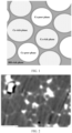
- FIG. 1 is a schematic diagram showing the characteristics of a main phase and a grain boundary phase of the surface layer of the permanent magnet in Example 1-1.
- FIG. 2 is a schematic diagram showing the characteristics of a main phase and a grain boundary phase of the core (500 ⁇ m away from the surface of permanent magnet) of the permanent magnet in Example 1-1.
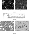
- FIG. 3 is EPMA images of Dy element and Pr element on a cross section of the core (50 ⁇ m away from the surface of the permanent magnet) of the permanent magnet in Example 1-1 (the left image is a distribution image of the Dy element, and the right image is a distribution image of the Pr element).
- FIG. 4 is an EPMA image in which the content of Ce element is linearly scanned through the main phase grains on the cross section of the core (50 ⁇ m away from the surface of the permanent magnet) of the permanent magnet in Example 1-1.
- the permanent magnet comprises at least a grain boundary and composite main phase grains, wherein the grain boundary comprises an RH-rich phase distributed in the form of an agglomerate within the grain boundary between the composite main phase grains, preferably at the intersection of any adjacent three or more composite main phase grains, and the RH-rich phase is continuously distributed along the grain boundary in the form of a thin-layer stripe.
- the RH-rich phase in the permanent magnet is a bright white region in the back scattering imaging mode of the scanning electron microscope, and is distributed between adjacent main phase grains or at the intersection of three or more main phase grains, and the content of the RH in the RH-rich phase is greater than that of the RH in the main phase grains.
- the composite main phase grains include Ce-rich main phase grains and Ce-poor main phase grains, which are dark gray regions in the back scattering imaging mode of the scanning electron microscope; in the Ce-rich main phase grains, the content of Ce is 14.5 wt%; in the Ce-poor main phase grains, the content of Ce is 0.5 wt%.
- the composite main phase grain has a core-shell structure, wherein the shell structure is a light gray region in the back scattering imaging mode of the scanning electron microscope, which is enriched with RL elements, and the content of the RL in the shell structure is greater than or equal to that of the RL in the core structure.
- FIG. 3 is a distribution image of the Dy element on the cross section of the core (50 ⁇ m away from the surface of the permanent magnet) of the permanent magnet in Example 1-1
- FIG. 5 is a distribution image of the Dy element on the cross section of the core (50 ⁇ m away from the surface of the permanent magnet) of the permanent magnet in Comparative Example 1-1.
- the sintered blanks with the same component in Example 1-1 and Comparative Example 1-1 were used for composite diffusion treatment.
- the change in the diffusion treatment method did not cause a change in the Dy content in the interior of the magnet along the diffusion direction, but the coercivity in the interior of the magnet was greatly improved.
- the inventors believed that the difference in the coercivity of the permanent magnets obtained by the two diffusion methods was not caused by the concentration gradient, but by the difference in microstructure.
- the Dy element in the sample of Example 1 formed more continuous enriched streaks along the grain boundary, whereas the Dy element in the sample of Comparative Example 1 was not enriched at the grain boundary but was replaced into the main phase by a diffusion replacement process.
- RL is contained in the diffusion material, it diffuses into the main phase more easily than RH, causing the main phase to form a core-shell structure.
- the content of the RL in the shell structure of the surface of the permanent magnet is relatively high, such that the RH in the diffusion material can be prevented from being replaced into the main phase structure, and thus the Dy element can diffuse along the grain boundary to the core of the permanent magnet.
- the RH element in the grain boundary phase of the permanent magnet prepared by the present disclosure can diffuse into the deeper position of the core away from the surface layer of the permanent magnet, indicating that the composite diffusion treatment effect of the present disclosure is good.
- the preparation method of the permanent magnet in this example was substantially the same as that in Example 1-1, except that the raw materials were weighed out according to components of a main phase alloy and an auxiliary phase alloy as shown in Table 3, respectively.
- Table 3 Raw material table for Examples 2-1 to 2-3 and Comparative Example 2-1 PrNd Ce Tb Co Al Ti Cu Ga Zr B Main phase alloy 30 1 1 1 0.5 0.2 0.1 0.4 0.2 1 Auxiliary phase alloy 17 15 0 1 0.2 0 0.3 0.0 0 0.98
- the preparation method of the permanent magnet in this example was substantially the same as that in Example 2-1, except that Pr was replaced by Nd in the diffusion slurry in step (5).
- the preparation method of the permanent magnet in this example was substantially the same as that in Example 2-1, except that the diffusion slurry in step (5) further comprised Cu, and the diffusion slurry was mixed according to a mass ratio of Dy single metal, Pr single metal, Cu metal, 4-hexylresorcinol, and ethanol of 4:3.5:0.5:2:1.
- the preparation method of the permanent magnet in this comparative example was substantially the same as that in Example 2-1, except that the diffusion slurry in step (5) did not comprise Pr.
- Example 2-1 The test results of the magnetic properties of the sintered blank in Example 2-1 and the permanent magnets prepared in Examples 2-1 to 2-3 and Comparative Example 2-1 are shown in Table 4. Table 4. Magnetic properties in Examples 2-1 to 2-3 and Comparative Example 2-1 Diffusion material Hcj Br Squareness Sintered blank / 1215 1.344 0.986
- Example 2-1 Dy-Pr 1720 1.315 0.970
- Example 2-2 Dy-Nd 1730 1.311 0.974
- Example 2-3 Dy-Pr-Cu 1732 1.313 0.978 Comparative Example 2-1
- Dy 1628 1.321 0.953
- the Hcj of the permanent magnet increased significantly when the composite diffusion material comprised RH and RL.
- the preparation method of the permanent magnet in this comparative example was substantially the same as that in Example 1-1, except that the raw materials were weighed out according to components of a main phase alloy and an auxiliary phase alloy as shown in Table 5, respectively.
- Table 5 Raw material table for Comparative Example 3 PrNd Ce Tb Co Al Ti Cu Ga Zr B Main phase alloy 30 1.5 1 1 0.5 0.2 0.1 0.4 0.2 1 Auxiliary phase alloy 17 15 0 1 0.2 0 0.3 0.0 0 0.98
- the preparation method of the permanent magnet in this comparative example was substantially the same as that in Example 1-1, except that an alloy was prepared by weighing the raw materials as shown in Table 7, that is, a blank was not prepared using a main phase alloy and an auxiliary phase alloy.
- Table 7 Raw material table for Comparative Example 4 PrNd Ce Tb Co Al Ti Cu Ga Zr B Alloy component 28 3.75 0.75 1 0.43 0.15 0.15 0.3 0.15 1
- the permanent magnet containing Ce was prepared by a conventional method in Comparative Example 4, that is, the raw material of Ce was added directly during smelting without using a main phase alloy and an auxiliary phase alloy to prepare a blank.
- Table 8 even if the sintered blank prepared by the conventional method was subjected to the composite diffusion treatment in the present disclosure, the improvement of the coercivity of the permanent magnet was limited.
Landscapes
- Engineering & Computer Science (AREA)
- Power Engineering (AREA)
- Chemical & Material Sciences (AREA)
- Crystallography & Structural Chemistry (AREA)
- Inorganic Chemistry (AREA)
- Manufacturing & Machinery (AREA)
- Hard Magnetic Materials (AREA)
- Powder Metallurgy (AREA)
- Manufacturing Cores, Coils, And Magnets (AREA)
Claims (10)
- R-Fe-B-Permanentmagnet, wobei der Permanentmagnet mindestens eine Korngrenze und zusammengesetzte Hauptphasenkörner umfasst,wobei die Korngrenze eine RH-reiche Phase umfasst, die in Form eines Agglomerats innerhalb der Korngrenze zwischen den zusammengesetzten Hauptphasenkörnern verteilt ist, vorzugsweise an der Schnittstelle von drei oder mehr beliebigen benachbarten zusammengesetzten Hauptphasenkörnern; wobei die RH-reiche Phase in Form eines Dünnschichtstreifens kontinuierlich entlang der Korngrenze verteilt ist;wobei RH in der Korngrenze einen Gehalt aufweist, der größer als der des RH in den Hauptphasenkörnern ist, und das RH mindestens eines ausgewählt aus schweren Seltenerdmetallen wie Dy, Tb und Ho ist;wobei das zusammengesetzte Hauptphasenkorn eine Kern-Schale-Struktur aufweist, wobei die Kern-Schale-Struktur eine Kernstruktur mit einer Phasenstruktur vom R-T-B-Typ und eine Schalenstruktur auf der äußeren Schicht der Kernstruktur umfasst,dadurch gekennzeichnet, dass die Kernstruktur Ce-reiche Hauptphasenkörner und Cearme Hauptphasenkörner umfasst, wobei Ce in den Ce-reichen Hauptphasenkörnern einen Gehalt von 1-15 Gew.-% aufweist, und Ce in den Ce-armen Hauptphasenkörnern einen Gehalt von 0,1-1 Gew.-% aufweist; und die RH-reiche Phase mindestens ein schweres Seltenerdmetall RH, ausgewählt aus Dy, Tb und Ho, mindestens ein leichtes Seltenerdmetall RL, ausgewählt aus Pr und Nd, und optional mindestens ein Metall M, ausgewählt aus Ga und Cu umfasst.
- R-Fe-B-Permanentmagnet nach Anspruch 1, wobei das RH in der Korngrenze einen Gehalt aufweist, der größer als der des RH in der Schalenstruktur ist;wobei der Permanentmagnet vorzugsweise RL umfasst, wobei das RL mindestens eines ausgewählt aus leichten Seltenerdmetallen wie Pr und Nd ist;und wobei das RL in der Schalenstruktur vorzugsweise einen Gehalt größer als oder gleich dem des RL in der Kernstruktur aufweist.
- R-Fe-B-Permanentmagnet nach Anspruch 1 oder 2, wobei die Phasenstruktur vom R-T-B-Typ mindestens die folgenden Komponenten umfasst:R, mit einem Gewichtsprozentsatz von 28 % ≤ R ≤ 35 %, wobei das R aus Neodym (Nd) und Cer (Ce) ausgewählt ist und wahlweise mindestens eines ausgewählt aus Scandium (Sc), Yttrium (Y), Lanthan (La), Cer (Ce), Praseodym (Pr), Samarium (Sm), Europium (Eu), Gadolinium (Gd), Terbium (Tb), Dysprosium (Dy), Holmium (Ho), Erbium (Er), Thulium (Tm), Ytterbium (Yb) und Lutetium (Lu) umfasst oder nicht umfasst;B, mit einem Gewichtsprozentsatz von 0,8 % ≤ B ≤ 1,2 %;M, mit einem Gewichtsprozentsatz von 0 ≤ M ≤ 5 %, wobei das M mindestens eines ausgewählt aus Aluminium (Al), Titan (Ti), Kupfer (Cu), Gallium (Ga), Zirkonium (Zr) und Niob (Nb) ist; undden Rest T, wobei das T aus Eisen (Fe) und wahlweise Kobalt (Co) besteht.
- R-Fe-B-Permanentmagnet nach einem der Ansprüche 1-3, wobei der Permanentmagnet von der Oberfläche bis zum Kern Phasenstrukturen der Korngrenze und der zusammengesetzten Hauptphasenkörner aufweist.
- Herstellungsverfahren für den Permanentmagneten nach einem der Ansprüche 1-4, wobei das Herstellungsverfahren umfasstMischen eines Pulvers aus einer Ce-armen Vorlegierung und eines Pulvers aus einer Ce-reichen Hilfslegierung, wobei Ce in der Ce-armen Vorlegierung einen Gehalt von 0,1-1 Gew.-% und Ce in der Ce-reichen Hilfslegierung einen Gehalt von mehr als 1 Gew.-% und nicht mehr als 15 Gew.-% aufweist,Durchführen von Pressformen an dem gemischten Pulver unter Einwirkung eines Magnetfelds, um einen Grünkörper zu erhalten,Durchführen von Sinterbehandlung an dem Grünkörper, um einen Rohling zu erhalten, undDurchführen einer zusammengesetzten Diffusionsbehandlung auf der Oberfläche des Rohlings mit einem Diffusionsmaterial, um den Permanentmagneten zu erhalten, wobei das Diffusionsmaterial RH, RL und wahlweise ein M-Pulver umfasst, wobei das RH mindestens ein schweres Seltenerdmetall, ausgewählt aus Dy, Tb und Ho ist; das RL mindestens ein leichtes Seltenerdmetall, ausgewählt aus Pr und Nd ist; und das M-Pulver aus Ga und/oder Cu ausgewählt ist.
- Herstellungsverfahren nach Anspruch 5, wobei das Pulver der Ce-armen Vorlegierung und das Pulver der Ce-reichen Hilfslegierung in einem Massenverhältnis von (1-50):1 vorliegen.
- Herstellungsverfahren nach Anspruch 5 oder 6, wobei nach dem Pressformen, Durchführen einer kaltisostatischen Pressbehandlung, um die Dichte des Rohlings weiter zu verbessern;
wobei die Sinterbehandlung vorzugsweise Erwärmen des Grünkörpers auf 1000-1100 °C unter einer Vakuumatmosphäre umfasst, um einen Rohling zu erhalten. - Herstellungsverfahren nach einem der Ansprüche 5-7, wobei die zusammengesetzte Diffusionsbehandlung umfasst: Anordnen des Diffusionsmaterials auf der Oberfläche des Rohlings und Durchführen einer Wärmebehandlung;
wobei die Oberfläche des Rohlings vorzugsweise gleichmäßig mit einer Aufschlämmung beschichtet wird, die das Diffusionsmaterial enthält. - Herstellungsverfahren nach einem der Ansprüche 5-8, wobei das Diffusionsmaterial die folgenden Komponenten umfasst: RH mit einem Gehalt von 20-70 Gew.-%, RL mit einem Gehalt von 20-70 Gew.-% und ein M-Pulver mit einem Gehalt von 0-10 Gew.-%;wobei das RH, das RL und das M-Pulver in dem Diffusionsmaterial vorzugsweise in einem Massenverhältnis von (1-10):(1-5):(0-2) vorliegen;wobei das RH und das RL vorzugsweise jeweils durch Pulver des RH und des RL bereitgestellt werden;wobei das Pulver des RH vorzugsweise mindestens eines ausgewählt aus einem einzelnen Metall des RH, einer Legierung des RH, einem Oxid des RH, einem Fluorid des RH, einem Hydrid des RH und einem Oxyfluorid des RH ist;und wobei das Pulver des RL vorzugsweise mindestens eines ausgewählt aus einem einzelnen Metall des RL, einer Legierung des RL, einem Oxid des RL, einem Fluorid des RL, einem Hydrid des RL und einem Oxyfluorid des RL ist.
- Verwendung des Permanentmagneten nach einem der Ansprüche 1-4, dadurch gekennzeichnet, dass der Permanentmagnet für einen Motor verwendet wird.
Applications Claiming Priority (1)
| Application Number | Priority Date | Filing Date | Title |
|---|---|---|---|
| CN202210962847.2A CN115410786B (zh) | 2022-08-11 | 2022-08-11 | 一种烧结R-Fe-B永磁体及其制备方法和应用 |
Publications (3)
| Publication Number | Publication Date |
|---|---|
| EP4325529A1 EP4325529A1 (de) | 2024-02-21 |
| EP4325529B1 true EP4325529B1 (de) | 2025-02-12 |
| EP4325529C0 EP4325529C0 (de) | 2025-02-12 |
Family
ID=84160073
Family Applications (1)
| Application Number | Title | Priority Date | Filing Date |
|---|---|---|---|
| EP23190721.3A Active EP4325529B1 (de) | 2022-08-11 | 2023-08-10 | Gesinterter r-fe-b-permanentmagnet, herstellungsverfahren und verwendung davon |
Country Status (5)
| Country | Link |
|---|---|
| US (1) | US20240055163A1 (de) |
| EP (1) | EP4325529B1 (de) |
| JP (1) | JP7749622B2 (de) |
| KR (1) | KR102738124B1 (de) |
| CN (1) | CN115410786B (de) |
Families Citing this family (5)
| Publication number | Priority date | Publication date | Assignee | Title |
|---|---|---|---|---|
| CN118231078B (zh) * | 2024-05-27 | 2024-09-10 | 南通正海磁材有限公司 | 一种高矫顽力的r-t-b永磁体及其制备方法和应用 |
| CN119480313A (zh) * | 2024-11-21 | 2025-02-18 | 安徽大学 | 一种多主相富Ce烧结磁体及其制备方法 |
| CN119626758B (zh) * | 2024-12-03 | 2025-11-14 | 中国第一汽车股份有限公司 | 钕铁硼磁体晶界扩散用的复合扩散剂、钕铁硼磁体的晶界扩散方法及钕铁硼磁体 |
| CN119811882A (zh) * | 2024-12-31 | 2025-04-11 | 福建省金龙稀土股份有限公司 | 一种r-t-b磁体扩散源、r-t-b磁体材料及其制备方法、应用 |
| CN121075804B (zh) * | 2025-11-06 | 2026-01-30 | 包头科田磁业有限公司 | 一种具有低温度系数的高性能铈磁体及其制备方法 |
Family Cites Families (12)
| Publication number | Priority date | Publication date | Assignee | Title |
|---|---|---|---|---|
| CN101517670B (zh) * | 2006-09-15 | 2012-11-07 | 因太金属株式会社 | NdFeB烧结磁铁的制造方法 |
| CN102800454B (zh) * | 2012-08-30 | 2017-03-22 | 钢铁研究总院 | 低成本双主相Ce永磁合金及其制备方法 |
| CN103996522B (zh) * | 2014-05-11 | 2016-06-15 | 沈阳中北通磁科技股份有限公司 | 一种含Ce的钕铁硼稀土永磁体的制造方法 |
| KR101624245B1 (ko) * | 2015-01-09 | 2016-05-26 | 현대자동차주식회사 | 희토류 영구 자석 및 그 제조방법 |
| JP2020095990A (ja) * | 2017-03-30 | 2020-06-18 | Tdk株式会社 | 希土類磁石及び回転機 |
| CN107026003B (zh) * | 2017-04-24 | 2020-02-07 | 烟台正海磁性材料股份有限公司 | 一种烧结钕铁硼磁体的制备方法 |
| JP2020150262A (ja) * | 2019-03-08 | 2020-09-17 | 日立金属株式会社 | R−t−b系焼結磁石 |
| JP7251264B2 (ja) * | 2019-03-28 | 2023-04-04 | Tdk株式会社 | R‐t‐b系永久磁石の製造方法 |
| KR102761632B1 (ko) * | 2020-04-08 | 2025-02-03 | 현대자동차주식회사 | 희토류 영구자석 및 그 제조방법 |
| JP7298533B2 (ja) * | 2020-04-21 | 2023-06-27 | トヨタ自動車株式会社 | 希土類磁石及びその製造方法 |
| CN113782330B (zh) * | 2021-09-16 | 2026-02-03 | 烟台东星磁性材料股份有限公司 | 镧铈添加钕铁硼磁体的制备方法 |
| CN114284019B (zh) * | 2021-12-27 | 2025-04-25 | 烟台正海磁性材料股份有限公司 | 一种高矫顽力钕铈铁硼永磁体及其制备方法和应用 |
-
2022
- 2022-08-11 CN CN202210962847.2A patent/CN115410786B/zh active Active
-
2023
- 2023-08-02 KR KR1020230101236A patent/KR102738124B1/ko active Active
- 2023-08-09 JP JP2023130066A patent/JP7749622B2/ja active Active
- 2023-08-10 EP EP23190721.3A patent/EP4325529B1/de active Active
- 2023-08-11 US US18/448,487 patent/US20240055163A1/en active Pending
Also Published As
| Publication number | Publication date |
|---|---|
| KR102738124B1 (ko) | 2024-12-03 |
| KR20240022406A (ko) | 2024-02-20 |
| CN115410786A (zh) | 2022-11-29 |
| CN115410786B (zh) | 2025-04-25 |
| JP7749622B2 (ja) | 2025-10-06 |
| US20240055163A1 (en) | 2024-02-15 |
| JP2024025736A (ja) | 2024-02-26 |
| EP4325529A1 (de) | 2024-02-21 |
| EP4325529C0 (de) | 2025-02-12 |
Similar Documents
| Publication | Publication Date | Title |
|---|---|---|
| EP4325529B1 (de) | Gesinterter r-fe-b-permanentmagnet, herstellungsverfahren und verwendung davon | |
| KR102670670B1 (ko) | NdFeB 자석 및 이의 제조 방법 및 응용 | |
| EP4336526A1 (de) | Kostengünstiger, hochkoerzitiver spitzenreicher neodym-eisen-bor-permanentmagnet und herstellungsverfahren dafür und verwendung davon | |
| EP4439593A1 (de) | Neodym-cerium-eisen-bor-permanentmagnet mit hoher koerzitivkraft sowie herstellungsverfahren dafür und verwendung davon | |
| CN111223624B (zh) | 一种钕铁硼磁体材料、原料组合物及制备方法和应用 | |
| EP3955267B1 (de) | Ndfeb-legierungspulver zur herstellung von gesinterten ndfeb-magneten hoher koerzitivkraft und verwendung davon | |
| EP2779179B1 (de) | R-T-B-basierte Seltenerdmagnetteilchen, Verfahren zur Herstellung der R-T-B-basierten Seltenerdmagnetteilchen und Verbundmagnet | |
| KR102632991B1 (ko) | 네오디뮴철붕소 자성체 재료, 원료조성물과 제조방법 및 응용 | |
| CN111243807B (zh) | 一种钕铁硼磁体材料、原料组合物及制备方法和应用 | |
| JP2023512541A (ja) | 微細結晶、高保磁力のネオジム鉄ボロン系焼結磁石及びその製造方法 | |
| US20250069784A1 (en) | Neodymium-iron-boron magnet as well as preparation method therefor and use thereof | |
| CN112509775A (zh) | 一种低量添加重稀土的钕铁硼磁体及其制备方法 | |
| EP4152349A1 (de) | Verfahren zur herstellung von ndfeb-magneten mit lanthan oder cer | |
| EP4156213B1 (de) | Herstellungsverfahren eines hochtemperaturbeständigen magneten | |
| EP4273893A1 (de) | Seltenerd-permanentmagnet und herstellungsverfahren dafür | |
| WO2025086914A1 (zh) | 一种基于多步扩散方法的高矫顽力混合稀土永磁材料及其制备方法 | |
| EP4307325A1 (de) | Haupt- und hilfslegierungsbasiertes neodym-eisen-bor-magnetmaterial und herstellungsverfahren dafür | |
| EP3919644A1 (de) | Seltenerdmagnet und herstellungsverfahren dafür | |
| CN114068169B (zh) | 一种节约Dy和Tb且提高永磁体矫顽力的永磁体及其制备方法 | |
| CN115938707B (zh) | 一种耐温性能优异的稀土永磁材料及其制备方法 | |
| CN107799251A (zh) | 一种高矫顽力共伴生稀土永磁体及其制备方法 | |
| EP4576128A1 (de) | Permanentmagnetmaterial mit mehrschichtiger struktur, herstellungsverfahren dafür und verwendung davon | |
| CN118824674B (zh) | 一种晶界扩散复合膜、稀土永磁体及制备方法 | |
| TW202443604A (zh) | 粉末組合物以及釹鐵硼磁體的製備方法 | |
| TW202443603A (zh) | 釹鐵硼基材以及釹鐵硼磁體的製備方法 |
Legal Events
| Date | Code | Title | Description |
|---|---|---|---|
| PUAI | Public reference made under article 153(3) epc to a published international application that has entered the european phase |
Free format text: ORIGINAL CODE: 0009012 |
|
| STAA | Information on the status of an ep patent application or granted ep patent |
Free format text: STATUS: REQUEST FOR EXAMINATION WAS MADE |
|
| STAA | Information on the status of an ep patent application or granted ep patent |
Free format text: STATUS: EXAMINATION IS IN PROGRESS |
|
| 17P | Request for examination filed |
Effective date: 20230810 |
|
| AK | Designated contracting states |
Kind code of ref document: A1 Designated state(s): AL AT BE BG CH CY CZ DE DK EE ES FI FR GB GR HR HU IE IS IT LI LT LU LV MC ME MK MT NL NO PL PT RO RS SE SI SK SM TR |
|
| 17Q | First examination report despatched |
Effective date: 20240131 |
|
| GRAP | Despatch of communication of intention to grant a patent |
Free format text: ORIGINAL CODE: EPIDOSNIGR1 |
|
| STAA | Information on the status of an ep patent application or granted ep patent |
Free format text: STATUS: GRANT OF PATENT IS INTENDED |
|
| INTG | Intention to grant announced |
Effective date: 20241023 |
|
| GRAS | Grant fee paid |
Free format text: ORIGINAL CODE: EPIDOSNIGR3 |
|
| GRAA | (expected) grant |
Free format text: ORIGINAL CODE: 0009210 |
|
| STAA | Information on the status of an ep patent application or granted ep patent |
Free format text: STATUS: THE PATENT HAS BEEN GRANTED |
|
| AK | Designated contracting states |
Kind code of ref document: B1 Designated state(s): AL AT BE BG CH CY CZ DE DK EE ES FI FR GB GR HR HU IE IS IT LI LT LU LV MC ME MK MT NL NO PL PT RO RS SE SI SK SM TR |
|
| REG | Reference to a national code |
Ref country code: GB Ref legal event code: FG4D |
|
| REG | Reference to a national code |
Ref country code: CH Ref legal event code: EP |
|
| REG | Reference to a national code |
Ref country code: DE Ref legal event code: R096 Ref document number: 602023002000 Country of ref document: DE |
|
| REG | Reference to a national code |
Ref country code: CH Ref legal event code: PK Free format text: BERICHTIGUNGEN |
|
| REG | Reference to a national code |
Ref country code: IE Ref legal event code: FG4D |
|
| RIN2 | Information on inventor provided after grant (corrected) |
Inventor name: LIU, ZHONGYU Inventor name: JIANG, YUNYING Inventor name: LIU, LEI Inventor name: SU, YUNTING Inventor name: AN, ZHONGXIN Inventor name: LI, WEI |
|
| U01 | Request for unitary effect filed |
Effective date: 20250228 |
|
| U07 | Unitary effect registered |
Designated state(s): AT BE BG DE DK EE FI FR IT LT LU LV MT NL PT RO SE SI Effective date: 20250310 |
|
| PG25 | Lapsed in a contracting state [announced via postgrant information from national office to epo] |
Ref country code: RS Free format text: LAPSE BECAUSE OF FAILURE TO SUBMIT A TRANSLATION OF THE DESCRIPTION OR TO PAY THE FEE WITHIN THE PRESCRIBED TIME-LIMIT Effective date: 20250512 |
|
| PG25 | Lapsed in a contracting state [announced via postgrant information from national office to epo] |
Ref country code: PL Free format text: LAPSE BECAUSE OF FAILURE TO SUBMIT A TRANSLATION OF THE DESCRIPTION OR TO PAY THE FEE WITHIN THE PRESCRIBED TIME-LIMIT Effective date: 20250212 |
|
| PG25 | Lapsed in a contracting state [announced via postgrant information from national office to epo] |
Ref country code: ES Free format text: LAPSE BECAUSE OF FAILURE TO SUBMIT A TRANSLATION OF THE DESCRIPTION OR TO PAY THE FEE WITHIN THE PRESCRIBED TIME-LIMIT Effective date: 20250212 |
|
| PG25 | Lapsed in a contracting state [announced via postgrant information from national office to epo] |
Ref country code: NO Free format text: LAPSE BECAUSE OF FAILURE TO SUBMIT A TRANSLATION OF THE DESCRIPTION OR TO PAY THE FEE WITHIN THE PRESCRIBED TIME-LIMIT Effective date: 20250512 Ref country code: IS Free format text: LAPSE BECAUSE OF FAILURE TO SUBMIT A TRANSLATION OF THE DESCRIPTION OR TO PAY THE FEE WITHIN THE PRESCRIBED TIME-LIMIT Effective date: 20250612 |
|
| PG25 | Lapsed in a contracting state [announced via postgrant information from national office to epo] |
Ref country code: HR Free format text: LAPSE BECAUSE OF FAILURE TO SUBMIT A TRANSLATION OF THE DESCRIPTION OR TO PAY THE FEE WITHIN THE PRESCRIBED TIME-LIMIT Effective date: 20250212 |
|
| PG25 | Lapsed in a contracting state [announced via postgrant information from national office to epo] |
Ref country code: GR Free format text: LAPSE BECAUSE OF FAILURE TO SUBMIT A TRANSLATION OF THE DESCRIPTION OR TO PAY THE FEE WITHIN THE PRESCRIBED TIME-LIMIT Effective date: 20250513 |
|
| U20 | Renewal fee for the european patent with unitary effect paid |
Year of fee payment: 3 Effective date: 20250723 |
|
| PG25 | Lapsed in a contracting state [announced via postgrant information from national office to epo] |
Ref country code: SM Free format text: LAPSE BECAUSE OF FAILURE TO SUBMIT A TRANSLATION OF THE DESCRIPTION OR TO PAY THE FEE WITHIN THE PRESCRIBED TIME-LIMIT Effective date: 20250212 |
|
| PG25 | Lapsed in a contracting state [announced via postgrant information from national office to epo] |
Ref country code: CZ Free format text: LAPSE BECAUSE OF FAILURE TO SUBMIT A TRANSLATION OF THE DESCRIPTION OR TO PAY THE FEE WITHIN THE PRESCRIBED TIME-LIMIT Effective date: 20250212 |
|
| PG25 | Lapsed in a contracting state [announced via postgrant information from national office to epo] |
Ref country code: SK Free format text: LAPSE BECAUSE OF FAILURE TO SUBMIT A TRANSLATION OF THE DESCRIPTION OR TO PAY THE FEE WITHIN THE PRESCRIBED TIME-LIMIT Effective date: 20250212 |
|
| PLBE | No opposition filed within time limit |
Free format text: ORIGINAL CODE: 0009261 |
|
| STAA | Information on the status of an ep patent application or granted ep patent |
Free format text: STATUS: NO OPPOSITION FILED WITHIN TIME LIMIT |
|
| 26N | No opposition filed |
Effective date: 20251113 |