EP4316948A1 - Steering wheel - Google Patents
Steering wheel Download PDFInfo
- Publication number
- EP4316948A1 EP4316948A1 EP22778299.2A EP22778299A EP4316948A1 EP 4316948 A1 EP4316948 A1 EP 4316948A1 EP 22778299 A EP22778299 A EP 22778299A EP 4316948 A1 EP4316948 A1 EP 4316948A1
- Authority
- EP
- European Patent Office
- Prior art keywords
- circuit board
- steering wheel
- printed circuit
- light
- housing
- Prior art date
- Legal status (The legal status is an assumption and is not a legal conclusion. Google has not performed a legal analysis and makes no representation as to the accuracy of the status listed.)
- Pending
Links
- 230000002787 reinforcement Effects 0.000 claims description 8
- 239000006260 foam Substances 0.000 description 4
- 230000000712 assembly Effects 0.000 description 3
- 238000000429 assembly Methods 0.000 description 3
- 239000003292 glue Substances 0.000 description 3
- 230000000694 effects Effects 0.000 description 2
- 230000003287 optical effect Effects 0.000 description 2
- 230000002093 peripheral effect Effects 0.000 description 2
- 238000005452 bending Methods 0.000 description 1
- 230000015572 biosynthetic process Effects 0.000 description 1
- 230000007423 decrease Effects 0.000 description 1
- 239000000835 fiber Substances 0.000 description 1
- 238000005286 illumination Methods 0.000 description 1
- 230000001788 irregular Effects 0.000 description 1
- 238000003466 welding Methods 0.000 description 1
Images


Classifications
-
- B—PERFORMING OPERATIONS; TRANSPORTING
- B60—VEHICLES IN GENERAL
- B60Q—ARRANGEMENT OF SIGNALLING OR LIGHTING DEVICES, THE MOUNTING OR SUPPORTING THEREOF OR CIRCUITS THEREFOR, FOR VEHICLES IN GENERAL
- B60Q3/00—Arrangement of lighting devices for vehicle interiors; Lighting devices specially adapted for vehicle interiors
- B60Q3/20—Arrangement of lighting devices for vehicle interiors; Lighting devices specially adapted for vehicle interiors for lighting specific fittings of passenger or driving compartments; mounted on specific fittings of passenger or driving compartments
- B60Q3/283—Steering wheels; Gear levers
-
- B—PERFORMING OPERATIONS; TRANSPORTING
- B62—LAND VEHICLES FOR TRAVELLING OTHERWISE THAN ON RAILS
- B62D—MOTOR VEHICLES; TRAILERS
- B62D1/00—Steering controls, i.e. means for initiating a change of direction of the vehicle
- B62D1/02—Steering controls, i.e. means for initiating a change of direction of the vehicle vehicle-mounted
- B62D1/04—Hand wheels
- B62D1/06—Rims, e.g. with heating means; Rim covers
-
- B—PERFORMING OPERATIONS; TRANSPORTING
- B60—VEHICLES IN GENERAL
- B60Q—ARRANGEMENT OF SIGNALLING OR LIGHTING DEVICES, THE MOUNTING OR SUPPORTING THEREOF OR CIRCUITS THEREFOR, FOR VEHICLES IN GENERAL
- B60Q3/00—Arrangement of lighting devices for vehicle interiors; Lighting devices specially adapted for vehicle interiors
- B60Q3/60—Arrangement of lighting devices for vehicle interiors; Lighting devices specially adapted for vehicle interiors characterised by optical aspects
- B60Q3/62—Arrangement of lighting devices for vehicle interiors; Lighting devices specially adapted for vehicle interiors characterised by optical aspects using light guides
- B60Q3/64—Arrangement of lighting devices for vehicle interiors; Lighting devices specially adapted for vehicle interiors characterised by optical aspects using light guides for a single lighting device
-
- B—PERFORMING OPERATIONS; TRANSPORTING
- B60—VEHICLES IN GENERAL
- B60Q—ARRANGEMENT OF SIGNALLING OR LIGHTING DEVICES, THE MOUNTING OR SUPPORTING THEREOF OR CIRCUITS THEREFOR, FOR VEHICLES IN GENERAL
- B60Q3/00—Arrangement of lighting devices for vehicle interiors; Lighting devices specially adapted for vehicle interiors
- B60Q3/60—Arrangement of lighting devices for vehicle interiors; Lighting devices specially adapted for vehicle interiors characterised by optical aspects
- B60Q3/62—Arrangement of lighting devices for vehicle interiors; Lighting devices specially adapted for vehicle interiors characterised by optical aspects using light guides
- B60Q3/66—Arrangement of lighting devices for vehicle interiors; Lighting devices specially adapted for vehicle interiors characterised by optical aspects using light guides for distributing light among several lighting devices
-
- B—PERFORMING OPERATIONS; TRANSPORTING
- B60—VEHICLES IN GENERAL
- B60Q—ARRANGEMENT OF SIGNALLING OR LIGHTING DEVICES, THE MOUNTING OR SUPPORTING THEREOF OR CIRCUITS THEREFOR, FOR VEHICLES IN GENERAL
- B60Q3/00—Arrangement of lighting devices for vehicle interiors; Lighting devices specially adapted for vehicle interiors
- B60Q3/70—Arrangement of lighting devices for vehicle interiors; Lighting devices specially adapted for vehicle interiors characterised by the purpose
-
- G—PHYSICS
- G02—OPTICS
- G02B—OPTICAL ELEMENTS, SYSTEMS OR APPARATUS
- G02B6/00—Light guides; Structural details of arrangements comprising light guides and other optical elements, e.g. couplings
- G02B6/0001—Light guides; Structural details of arrangements comprising light guides and other optical elements, e.g. couplings specially adapted for lighting devices or systems
- G02B6/0005—Light guides; Structural details of arrangements comprising light guides and other optical elements, e.g. couplings specially adapted for lighting devices or systems the light guides being of the fibre type
- G02B6/001—Light guides; Structural details of arrangements comprising light guides and other optical elements, e.g. couplings specially adapted for lighting devices or systems the light guides being of the fibre type the light being emitted along at least a portion of the lateral surface of the fibre
-
- B—PERFORMING OPERATIONS; TRANSPORTING
- B60—VEHICLES IN GENERAL
- B60Y—INDEXING SCHEME RELATING TO ASPECTS CROSS-CUTTING VEHICLE TECHNOLOGY
- B60Y2400/00—Special features of vehicle units
- B60Y2400/83—Steering input members
-
- B—PERFORMING OPERATIONS; TRANSPORTING
- B62—LAND VEHICLES FOR TRAVELLING OTHERWISE THAN ON RAILS
- B62D—MOTOR VEHICLES; TRAILERS
- B62D1/00—Steering controls, i.e. means for initiating a change of direction of the vehicle
- B62D1/02—Steering controls, i.e. means for initiating a change of direction of the vehicle vehicle-mounted
- B62D1/04—Hand wheels
- B62D1/046—Adaptations on rotatable parts of the steering wheel for accommodation of switches
Definitions
- the present invention relates to automobile parts, in particular to a steering wheel.
- Steering wheels of some automobiles can emit light.
- Steering wheel rims of these steering wheels are illuminated when light-emitting members emit light, so that light is emitted at the wheel rims of the steering wheels.
- the steering wheel is provided with the light-emitting steering wheel rim, so that in one aspect, a decorative effect is achieved, and the steering wheel is more aesthetically pleasing.
- the light-emitting steering wheel rim can provide an illumination function.
- the steering wheel rim is provided with a light-emitting assembly for emitting light, the steering wheel becomes bulky and heavy. Correspondingly, this results in higher requirements on the mechanical strength of the frame of the steering wheel, thereby increasing design difficulty of the steering wheel.
- the objective of the present invention is to provide a relatively small and lightweight steering wheel. Further, the objective of the present invention is also to provide a steering wheel of which a light-emitting assembly does not result in an increase in design difficulty.
- a steering wheel comprising a steering wheel rim and a light-emitting assembly, the steering wheel rim having an inner cavity, and the light-emitting assembly being provided in the inner cavity so as to be used to cause the steering wheel rim to emit light, wherein,
- the light-emitting assembly further comprises a light guide member
- the steering wheel rim comprises a housing, the light guide member being provided on a first side surface of the housing, and the first printed circuit board and the second printed circuit board being provided on a second side surface of the housing opposite the first side surface.
- the housing is provided with a recess for accommodating the light guide member, and the recess is provided with a protruding portion for securing the light guide member.
- the light guide member is configured to be a light guide tube
- the protruding portion comprises a first protruding portion, a second protruding portion, a third protruding portion, and a fourth protruding portion
- one of the light guide member and the recess is provided with a position-limiting protruding portion, and the other is provided with a position-limiting recess, the position-limiting protruding portion and the position-limiting recess cooperating to limit the position of the light guide member relative to the housing.
- another side of the first printed circuit board opposite a side where the light source is located is provided with a reinforcement portion, and at least a portion of the reinforcement portion corresponds to the light source in a thickness direction of the first printed circuit board.
- the first printed circuit board is secured to the housing by means of a securing member and at the reinforcement portion.
- the housing is provided with a slide slot
- the second printed circuit board is configured to slide in the slide slot relative to the housing so as to be secured to the housing.
- one end of the first printed circuit board is inserted into an interface provided on the second printed circuit board so as to achieve the electrical connection between the first printed circuit board and the second printed circuit board.
- the steering wheel rim further comprises a cap secured on the housing, and light emitted by the light source passes through a hole of the housing and the light guide member, and is then emitted from the cap so as to cause the steering wheel rim to emit light.
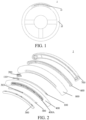
- FIG. 1 schematically illustrates a steering wheel according to an embodiment of the present invention.
- the steering wheel according to the embodiment of the present invention is described below with reference to FIG. 1 .
- the steering wheel 1 includes a steering wheel rim 20 and a light-emitting assembly 10, and the light-emitting assembly 10 is provided at the steering wheel rim 20.
- the steering wheel rim 20 has an inner cavity, and the light-emitting assembly 10 is provided in the inner cavity of the steering wheel rim 20 so as to be used to cause the steering wheel rim 20 to emit light.
- the light-emitting assembly 10 is provided in the inner cavity of the steering wheel rim 20, and the entire outer surface of the steering wheel rim 20 is smooth.
- the steering wheel rim 20 where the light-emitting assembly 10 is provided is flush with the remaining portion of the steering wheel rim 20, so that the steering wheel rim 20 has a consistent and complete appearance.
- the light-emitting assembly 10 of this embodiment is configured to be in the shape of a circular arc, and correspondingly, the light-emitting assembly 10 has a circular arc capable of emitting light
- the steering wheel of the present invention is not limited thereto, and the light-emitting assembly may also be configured to be in other shapes, such as semi-circular, circular, and even other irregular shapes.
- FIG. 2 schematically illustrates a light-emitting assembly in a steering wheel according to an embodiment of the present invention.
- the light-emitting assembly in the steering wheel according to the embodiment of the present invention is described below with reference to FIG. 2 .
- the steering wheel 1 according to the embodiment of the present invention is illustrated by means of an exploded view so as to more clearly illustrate the structure of the steering wheel 1.
- the light-emitting assembly 10 includes a light source 110, a first printed circuit board 100, and a second printed circuit board 200. The foregoing components of the light-emitting assembly 10 are described in detail below.
- the light source 110 is provided on the first printed circuit board 100.
- left and right ends of the first printed circuit board 100 are each provided with one light source 110 (e.g., an LED).
- the second printed circuit board 200 is provided with a control assembly for controlling the light source 110, so as to, for example, control actions such as turning on and turning off the light source 110.
- one end of the first printed circuit board 100 an end portion of the first printed circuit board 100 located on a left side of the left light source 110 in FIG.
- the second printed circuit board 200 is configured to control the light source 110 by means of the electrical connection with the first printed circuit board 100.
- the first printed circuit board 100 is configured to be a flexible circuit board
- the second printed circuit board 200 is configured to be a rigid circuit board.
- the light source is provided on the flexible circuit board
- the control assembly for controlling the light source is provided on the rigid printed circuit board, so that the size of the rigid circuit board can be configured to be as small as possible, and the flexible circuit board is used to meet requirements on distribution, mounting, etc., of the light source of the light-emitting assembly, thereby enabling the steering wheel of the present invention to emit light, ensuring that the light-emitting assembly and correspondingly the steering wheel are relatively small and lightweight, and ensuring that the light-emitting assembly does not result in an increase in design difficulty.
- the steering wheel 10 according to the embodiment of the present invention is further described below with reference to FIG. 2 .
- the light-emitting assembly 10 according to the embodiment of the present invention further includes a light guide member 300, and the steering wheel rim 20 includes a housing 400.
- the light guide member 300 may be configured to be tubular, and has a first end 301 and a second end 302 that are bent. Further, in order to achieve uniform light emission, a portion of an outer peripheral surface of the light guide member 300 is machined into a flat surface, and the flat surface is provided with a plurality of optical teeth 304. The plurality of optical teeth 304 are arranged in a lengthwise direction of the light guide member 300.
- the light guide member 300 may also be a light guide fiber.
- the housing 400 is substantially in the shape of a half arc.
- two ends of the housing 400 are secured (e.g., bonded) to a foam body 700.
- the light guide member 300 is provided on a first side surface of the housing 400, and the first printed circuit board 100 and the second printed circuit board 200 are provided on a second side surface of the housing 400 opposite the first side surface.
- the first side surface of the housing 400 corresponds to a lower side surface thereof (shown in FIG. 2 )
- the second side surface of the housing 400 corresponds to an upper side surface thereof (not shown in FIG. 2 ).
- the steering wheel 1 further includes a cap 500, a rigid body 600, the foam body 700, and a sheath 800.
- the rigid body 600 is provided in the foam body 700 so as to provide rigid support for the entire steering wheel rim 20.
- the foam body 700 is used to secure the housing 400, and can also contribute, at least partially, to the formation of the shape of the steering wheel rim.
- the sheath 800 defines an outer peripheral surface of the steering wheel rim 20 together with the cap 500, and the sheath 800 is secured to the housing 400 (e.g., a portion of the sheath is inserted into a slit provided on the housing 400, as shown in FIG. 4(b) and FIG. 4(c) ).
- the cap 500 is configured to be a transparent member, and is secured to the housing 400. Light emitted by the light source 110 passes through a hole of the housing 400 (as shown in FIG. 6(a) or FIG. 6(b) ) and the light guide member 300, and is then emitted from the cap 500 so as to cause the steering wheel rim to emit light.
- the first side surface of the housing 400 is provided with a recess 400A. This is described in further detail below.
- FIG. 3 schematically illustrates a partial view of a light-emitting assembly in a steering wheel according to an embodiment of the present invention.
- FIG. 4(a) is an enlarged view of a portion A in FIG. 3, and FIG. 4(b) and FIG. 4(c) are cross-sectional views acquired along lines E-E and I-I in FIG. 4(a) , respectively.
- FIG. 5(a) is an enlarged view of a portion B in FIG. 3
- FIG. 5(b) is a cross-sectional view acquired along a line F-F in FIG. 5(a).
- FIG. 6(a) is an enlarged view of a portion C in FIG. 3
- FIG. 6(b) and FIG. 6(c) are cross-sectional views acquired along lines H-H and G-G in FIG. 4(a) , respectively.
- the steering wheel according to the embodiment of the present invention is further described below with reference to these accompanying drawings.
- the recess 400A provided on the first side surface of the housing 400 is provided with structures for respectively securing the light guide member 300 and the cap 500.
- the housing 400 is provided with a fifth protruding portion 405 at the recess 400A.
- the fifth protruding portion 405 is inserted into a hole of the cap 500, so that the cap 500 is secured to the housing 400.
- the fifth protruding portions 405 are arranged in pairs and distributed evenly along the recess 400A.
- the housing 400 is provided with a fourth protruding portion 404 at the recess 400A, and the fourth protruding portion 404 is configured to abut an upper side of the light guide member 300 so as to hold the light guide member 300 to the housing 400.
- the housing 400 is provided with a first protruding portion 401, a second protruding portion 402, and a third protruding portion 403 at the recess 400A, and the first protruding portion 401, the second protruding portion 402, and the third protruding portion 403 are provided at each of hook-shaped end portions 301 and 302 of the light guide member 300. As shown in FIG.
- the first protruding portion 401 and the second protruding portion 402 at each hook-shaped end portion are opposite each other in a radial direction of the steering wheel rim 20 and abut the light guide member 300 so as to prevent the light guide member 300 from rotating about an axial direction thereof.
- the third protruding portion 403 abuts an end side of the light guide member 300 so as to prevent the end portion of the light guide member 300 from bending upward relative to the housing 400. Therefore, the first protruding portion 401, the second protruding portion 402, and the third protruding portion 403 advantageously prevent the light guide member 300 from rotating relative to the housing 400.
- each of the first protruding portion 401, the second protruding portion 402, and the third protruding portion 403 is configured to be at a distance from the housing 400, and the distance is, for example, 0.1-0.2 millimeters, so that the light guide member 300 is smoothly mounted on the housing 400.
- the light guide member 300 is provided with a position-limiting protruding portion 303 (the position-limiting protruding portion 303 is more clearly shown in FIG. 8 ).
- the recess is provided with a position-limiting recess (not shown), and the position-limiting protruding portion 303 and the position-limiting recess cooperate to limit the position of the light guide member 300 relative to the housing 400 so as to quickly position the light guide member 300 in the housing 300 during mounting.
- the position-limiting protruding portion may be provided on the housing, and correspondingly the position-limiting recess is provided on the light guide member.
- FIG. 7(a) schematically illustrates a partial view of a light-emitting assembly in a steering wheel according to an embodiment of the present invention.
- FIG. 7(b) is an enlarged view of a portion J in FIG. 7(a) .
- the housing 400 is provided with a slide slot 406, and the second printed circuit board 200 is configured to slide in the slide slot 406 relative to the housing 400 so as to be secured to the housing 400.
- the second printed circuit board 300 slides from the right to the left in the slide slot 406.
- the thickness of the slide slot 406 decreases gradually from the right to the left, so that when the second printed circuit board 300 sliding leftwards in the slide slot 406 reaches a position where the thickness of the slide slot 406 is slightly less than the thickness of the second printed circuit board, the second printed circuit board is held tightly in the slide slot 406.
- the second printed circuit board may also be directly welded to the housing, or secured to the housing by means of securing members such as a screw, etc.
- the tubular light guide member may also be prevented from rotating relative to the housing in another manner. An anti-rotation structure for the light guide member may even be omitted when the light guide member is not tubular in shape.
- FIG. 9(a), FIG. 9(b), and FIG. 9(c) respectively schematically illustrate partial views of light-emitting assemblies in steering wheels according to different embodiments of the present invention.
- the light-emitting assemblies according to the embodiments of the present invention are further described below with reference to FIG. 9(a), FIG. 9(b), and FIG. 9(c) .
- the first printed circuit board 100 is welded to the housing 400. Specifically, the first printed circuit board 100 is secured to the housing 400 by a weld leg 701. An upper side of the first printed circuit board 100 is provided with the light source 110, and another side (i.e., a lower side) opposite the side where the light source 100 is located is provided with a reinforcement portion 704, and at least a portion of the reinforcement portion 704 corresponds to the light source 100 in a thickness direction of the first printed circuit board 100 so as to provide rigid support for the light source 100. In addition, a side surface of the first printed circuit board 100 where the light source 100 is provided is further provided with a glue 705. The glue 705 is represented by a dotted portion in FIG.
- the glue 705 is used to bond the first printed circuit board 100 to the housing 400 so that the first printed circuit board 100 and the housing 400 are more firmly secured to each other. It can be understood that the first printed circuit board 100 is not necessarily secured to the housing 400 by means of welding, and may also be secured to the housing in other manners, for example, by means of a screw (as shown in FIG. 9(b) ), a fastener (as shown in FIG. 9(c) ), etc.
Landscapes
- Engineering & Computer Science (AREA)
- Mechanical Engineering (AREA)
- Chemical & Material Sciences (AREA)
- Combustion & Propulsion (AREA)
- Transportation (AREA)
- Physics & Mathematics (AREA)
- General Physics & Mathematics (AREA)
- Optics & Photonics (AREA)
- Arrangements Of Lighting Devices For Vehicle Interiors, Mounting And Supporting Thereof, Circuits Therefore (AREA)
- Non-Portable Lighting Devices Or Systems Thereof (AREA)
- Steering Controls (AREA)
- Planar Illumination Modules (AREA)
Applications Claiming Priority (2)
| Application Number | Priority Date | Filing Date | Title |
|---|---|---|---|
| CN202110352053.XA CN115140150A (zh) | 2021-03-31 | 2021-03-31 | 方向盘 |
| PCT/CN2022/071546 WO2022206110A1 (zh) | 2021-03-31 | 2022-01-12 | 方向盘 |
Publications (1)
| Publication Number | Publication Date |
|---|---|
| EP4316948A1 true EP4316948A1 (en) | 2024-02-07 |
Family
ID=83405207
Family Applications (1)
| Application Number | Title | Priority Date | Filing Date |
|---|---|---|---|
| EP22778299.2A Pending EP4316948A1 (en) | 2021-03-31 | 2022-01-12 | Steering wheel |
Country Status (6)
| Country | Link |
|---|---|
| US (1) | US20240166126A1 (zh) |
| EP (1) | EP4316948A1 (zh) |
| JP (1) | JP2024509419A (zh) |
| KR (1) | KR20230163457A (zh) |
| CN (1) | CN115140150A (zh) |
| WO (1) | WO2022206110A1 (zh) |
Family Cites Families (5)
| Publication number | Priority date | Publication date | Assignee | Title |
|---|---|---|---|---|
| DE102011112134A1 (de) * | 2011-09-01 | 2013-03-07 | Audi Ag | Anordnung zum Verkleiden eines Bauteils, Bauteil und Kraftfahrzeug |
| CN201980283U (zh) * | 2011-04-22 | 2011-09-21 | 王建智 | 可发光的方向盘 |
| DE102012011875A1 (de) * | 2012-06-13 | 2013-12-19 | Valeo Schalter Und Sensoren Gmbh | Manuell bedienbare Schaltvorrichtung für ein Fahrzeug mit Sensoraktivierungseinrichtung |
| WO2016014692A1 (en) * | 2014-07-23 | 2016-01-28 | Tk Holdings Inc. | Steering grip light bar systems |
| DE102018200591A1 (de) * | 2018-01-15 | 2019-07-18 | Bayerische Motoren Werke Aktiengesellschaft | Lenkrad für ein Kraftfahrzeug, Verfahren zum Bereitstellen eines Lenkrads für ein Kraftfahrzeug sowie Kraftfahrzeug |
-
2021
- 2021-03-31 CN CN202110352053.XA patent/CN115140150A/zh active Pending
-
2022
- 2022-01-12 WO PCT/CN2022/071546 patent/WO2022206110A1/zh active Application Filing
- 2022-01-12 KR KR1020237036465A patent/KR20230163457A/ko unknown
- 2022-01-12 US US18/552,368 patent/US20240166126A1/en active Pending
- 2022-01-12 JP JP2023552483A patent/JP2024509419A/ja active Pending
- 2022-01-12 EP EP22778299.2A patent/EP4316948A1/en active Pending
Also Published As
| Publication number | Publication date |
|---|---|
| CN115140150A (zh) | 2022-10-04 |
| KR20230163457A (ko) | 2023-11-30 |
| WO2022206110A1 (zh) | 2022-10-06 |
| JP2024509419A (ja) | 2024-03-01 |
| US20240166126A1 (en) | 2024-05-23 |
Similar Documents
| Publication | Publication Date | Title |
|---|---|---|
| US9457707B2 (en) | Vehicle auxiliary lamp unit | |
| US10661705B2 (en) | Exterior rearview mirror with turn signal unit | |
| EP4316948A1 (en) | Steering wheel | |
| CN210398743U (zh) | 厚壁件光学组件、车灯和车辆 | |
| US9908459B2 (en) | LED fog lamp | |
| JP2010052442A (ja) | 車両用ランプおよび車両用ランプが組込まれたドアミラー | |
| US6059436A (en) | Vehicle lamp | |
| JP6846922B2 (ja) | 車両用灯具 | |
| JP4222056B2 (ja) | 車両用灯具 | |
| JP4185837B2 (ja) | マーカーランプおよび光源ユニット | |
| EP3647168A1 (en) | Detachable and rotable light-vehicle light | |
| US10941918B1 (en) | Vehicle lamp assembly | |
| WO2016143588A1 (ja) | 自動車のハイマウントストップランプ | |
| JP2021177451A (ja) | 車両用灯具 | |
| JP5260471B2 (ja) | 自動車用信号灯の光源取付構造 | |
| CN219102783U (zh) | 一种车灯的光源结构 | |
| EP4331946A1 (en) | Steering wheel | |
| JP2010052444A (ja) | 車両用ランプおよび車両用ランプが組込まれたドアミラー | |
| CN212178767U (zh) | 一种车灯导光板 | |
| US20180119918A1 (en) | Vehicle lighting fixture | |
| JP6226699B2 (ja) | 車両用灯具 | |
| JP6994893B2 (ja) | 灯具 | |
| TWI665405B (zh) | 車燈透鏡組配裝置 | |
| TWM495319U (zh) | 車輛用複合燈 | |
| JP2021097013A (ja) | 車両用灯具 |
Legal Events
| Date | Code | Title | Description |
|---|---|---|---|
| STAA | Information on the status of an ep patent application or granted ep patent |
Free format text: STATUS: THE INTERNATIONAL PUBLICATION HAS BEEN MADE |
|
| PUAI | Public reference made under article 153(3) epc to a published international application that has entered the european phase |
Free format text: ORIGINAL CODE: 0009012 |
|
| STAA | Information on the status of an ep patent application or granted ep patent |
Free format text: STATUS: REQUEST FOR EXAMINATION WAS MADE |
|
| 17P | Request for examination filed |
Effective date: 20231011 |
|
| AK | Designated contracting states |
Kind code of ref document: A1 Designated state(s): AL AT BE BG CH CY CZ DE DK EE ES FI FR GB GR HR HU IE IS IT LI LT LU LV MC MK MT NL NO PL PT RO RS SE SI SK SM TR |