EP4298028B1 - Vorrichtung zum abdichten eines behälters für flüssige produkte - Google Patents
Vorrichtung zum abdichten eines behälters für flüssige produkte Download PDFInfo
- Publication number
- EP4298028B1 EP4298028B1 EP22710679.6A EP22710679A EP4298028B1 EP 4298028 B1 EP4298028 B1 EP 4298028B1 EP 22710679 A EP22710679 A EP 22710679A EP 4298028 B1 EP4298028 B1 EP 4298028B1
- Authority
- EP
- European Patent Office
- Prior art keywords
- axial
- sealing
- radial
- collar
- cover
- Prior art date
- Legal status (The legal status is an assumption and is not a legal conclusion. Google has not performed a legal analysis and makes no representation as to the accuracy of the status listed.)
- Active
Links
Images
Classifications
-
- B—PERFORMING OPERATIONS; TRANSPORTING
- B65—CONVEYING; PACKING; STORING; HANDLING THIN OR FILAMENTARY MATERIAL
- B65D—CONTAINERS FOR STORAGE OR TRANSPORT OF ARTICLES OR MATERIALS, e.g. BAGS, BARRELS, BOTTLES, BOXES, CANS, CARTONS, CRATES, DRUMS, JARS, TANKS, HOPPERS, FORWARDING CONTAINERS; ACCESSORIES, CLOSURES, OR FITTINGS THEREFOR; PACKAGING ELEMENTS; PACKAGES
- B65D41/00—Caps, e.g. crown caps or crown seals, i.e. members having parts arranged for engagement with the external periphery of a neck or wall defining a pouring opening or discharge aperture; Protective cap-like covers for closure members, e.g. decorative covers of metal foil or paper
- B65D41/32—Caps or cap-like covers with lines of weakness, tearing-strips, tags, or like opening or removal devices, e.g. to facilitate formation of pouring openings
- B65D41/58—Caps or cap-like covers combined with stoppers
-
- B—PERFORMING OPERATIONS; TRANSPORTING
- B65—CONVEYING; PACKING; STORING; HANDLING THIN OR FILAMENTARY MATERIAL
- B65D—CONTAINERS FOR STORAGE OR TRANSPORT OF ARTICLES OR MATERIALS, e.g. BAGS, BARRELS, BOTTLES, BOXES, CANS, CARTONS, CRATES, DRUMS, JARS, TANKS, HOPPERS, FORWARDING CONTAINERS; ACCESSORIES, CLOSURES, OR FITTINGS THEREFOR; PACKAGING ELEMENTS; PACKAGES
- B65D45/00—Clamping or other pressure-applying devices for securing or retaining closure members
- B65D45/02—Clamping or other pressure-applying devices for securing or retaining closure members for applying axial pressure to engage closure with sealing surface
- B65D45/30—Annular members, e.g. with snap-over action or screw-threaded
-
- B—PERFORMING OPERATIONS; TRANSPORTING
- B65—CONVEYING; PACKING; STORING; HANDLING THIN OR FILAMENTARY MATERIAL
- B65D—CONTAINERS FOR STORAGE OR TRANSPORT OF ARTICLES OR MATERIALS, e.g. BAGS, BARRELS, BOTTLES, BOXES, CANS, CARTONS, CRATES, DRUMS, JARS, TANKS, HOPPERS, FORWARDING CONTAINERS; ACCESSORIES, CLOSURES, OR FITTINGS THEREFOR; PACKAGING ELEMENTS; PACKAGES
- B65D51/00—Closures not otherwise provided for
- B65D51/002—Closures to be pierced by an extracting-device for the contents and fixed on the container by separate retaining means
-
- B—PERFORMING OPERATIONS; TRANSPORTING
- B65—CONVEYING; PACKING; STORING; HANDLING THIN OR FILAMENTARY MATERIAL
- B65D—CONTAINERS FOR STORAGE OR TRANSPORT OF ARTICLES OR MATERIALS, e.g. BAGS, BARRELS, BOTTLES, BOXES, CANS, CARTONS, CRATES, DRUMS, JARS, TANKS, HOPPERS, FORWARDING CONTAINERS; ACCESSORIES, CLOSURES, OR FITTINGS THEREFOR; PACKAGING ELEMENTS; PACKAGES
- B65D51/00—Closures not otherwise provided for
- B65D51/18—Arrangements of closures with protective outer cap-like covers or of two or more co-operating closures
-
- B—PERFORMING OPERATIONS; TRANSPORTING
- B65—CONVEYING; PACKING; STORING; HANDLING THIN OR FILAMENTARY MATERIAL
- B65D—CONTAINERS FOR STORAGE OR TRANSPORT OF ARTICLES OR MATERIALS, e.g. BAGS, BARRELS, BOTTLES, BOXES, CANS, CARTONS, CRATES, DRUMS, JARS, TANKS, HOPPERS, FORWARDING CONTAINERS; ACCESSORIES, CLOSURES, OR FITTINGS THEREFOR; PACKAGING ELEMENTS; PACKAGES
- B65D55/00—Accessories for container closures not otherwise provided for
- B65D55/02—Locking devices; Means for discouraging or indicating unauthorised opening or removal of closure
- B65D55/06—Deformable or tearable wires, strings or strips; Use of seals
- B65D55/08—Annular elements encircling container necks
- B65D55/0863—Plastic snap-on cap-like collars having frangible parts
-
- B—PERFORMING OPERATIONS; TRANSPORTING
- B65—CONVEYING; PACKING; STORING; HANDLING THIN OR FILAMENTARY MATERIAL
- B65D—CONTAINERS FOR STORAGE OR TRANSPORT OF ARTICLES OR MATERIALS, e.g. BAGS, BARRELS, BOTTLES, BOXES, CANS, CARTONS, CRATES, DRUMS, JARS, TANKS, HOPPERS, FORWARDING CONTAINERS; ACCESSORIES, CLOSURES, OR FITTINGS THEREFOR; PACKAGING ELEMENTS; PACKAGES
- B65D2251/00—Details relating to container closures
- B65D2251/0003—Two or more closures
- B65D2251/0006—Upper closure
- B65D2251/0015—Upper closure of the 41-type
-
- B—PERFORMING OPERATIONS; TRANSPORTING
- B65—CONVEYING; PACKING; STORING; HANDLING THIN OR FILAMENTARY MATERIAL
- B65D—CONTAINERS FOR STORAGE OR TRANSPORT OF ARTICLES OR MATERIALS, e.g. BAGS, BARRELS, BOTTLES, BOXES, CANS, CARTONS, CRATES, DRUMS, JARS, TANKS, HOPPERS, FORWARDING CONTAINERS; ACCESSORIES, CLOSURES, OR FITTINGS THEREFOR; PACKAGING ELEMENTS; PACKAGES
- B65D2251/00—Details relating to container closures
- B65D2251/0003—Two or more closures
- B65D2251/0068—Lower closure
- B65D2251/009—Lower closure of the 51-type
-
- B—PERFORMING OPERATIONS; TRANSPORTING
- B65—CONVEYING; PACKING; STORING; HANDLING THIN OR FILAMENTARY MATERIAL
- B65D—CONTAINERS FOR STORAGE OR TRANSPORT OF ARTICLES OR MATERIALS, e.g. BAGS, BARRELS, BOTTLES, BOXES, CANS, CARTONS, CRATES, DRUMS, JARS, TANKS, HOPPERS, FORWARDING CONTAINERS; ACCESSORIES, CLOSURES, OR FITTINGS THEREFOR; PACKAGING ELEMENTS; PACKAGES
- B65D2401/00—Tamper-indicating means
- B65D2401/15—Tearable part of the closure
- B65D2401/25—Non-metallic tear-off strips
Definitions
- the present invention relates to a device for sealing a fluid product reservoir, for example a bottle containing a pharmaceutical fluid product.
- a preferred field of application of the present invention is that of stoppers which can be pierced using a needle to remove all or part of the fluid product contained in the reservoir.
- a closure device of this type comprises a cap of relatively soft material, such as an elastomer, which is force-fitted into the neck of the tank.
- a cap of relatively soft material such as an elastomer
- the cap is pushed into its closed position, in which it seals the tank in a sealed manner, and a metal capsule is mounted, in particular crimped, around the cap to secure it to the neck of the tank.
- the capsule if the capsule is not perforated to allow the cap to be pierced to remove the fluid contained in the reservoir, the capsule must be completely removed before use, which can be difficult. This also implies a risk of accidental removal of the cap, with the consequent risk of loss of the fluid contained in the reservoir.
- a metal capsule generally made of aluminum
- the use of a part metal is disadvantageous in terms of recycling and environmental friendliness.
- the removable protective cover can usually be removed and replaced easily, so that it is impossible to know whether or not product has already been withdrawn from the tank.
- the integrity of the fluid contained in the tank is also not guaranteed.
- this type of shutter device does not allow for high-speed assembly, for example using a machine that can simultaneously assemble several dozen shutter devices.
- the present invention aims to remedy the aforementioned drawbacks.
- the present invention aims in particular to provide a sealing device which guarantees the integrity of the fluid contained in the tank until its use.
- the present invention also aims to provide a sealing device which includes a tamper-proof first use indicator.
- the present invention also aims to provide a sealing device which makes it possible to use a stopper provided with a coating on the face in contact with the fluid product.
- the present invention also aims to provide a sealing device which is completely free of metal.
- the present invention as disclosed in claim 1 also aims to provide a sealing device which can be assembled at high speeds, in particular in an assembly machine capable of assembling several tens, for example one hundred, devices simultaneously.
- the present invention also aims to provide a sealing device which is simple and inexpensive to manufacture and assemble.
- said axial barrel of said plug comprises on its outer surface at least one sealing bead which cooperates with the interior of said neck of said tank to guarantee the sealed sealing of said tank.
- said radial plate of said plug has an external diameter greater than the external diameter of said axial barrel, and comprises at least one annular projection extending downwards which, in the sealing position, cooperates with said upper axial edge of said neck.
- said annular projection is peripheral and is, during the assembly of said sealing device on said neck of said tank, crushed on said upper axial edge of said neck to achieve sealing with said tank.
- said radial plate comprises a central tapping zone defined inside an axial ring.
- the radially external edge of said axial ring is conical, widening upwards.
- said radial flange of said fixing ring is positioned on said radial plate of said plug, said central opening receiving said axial ring and said tapping zone of said plug.
- the radial edge of said central opening snaps onto said radially external conical edge of said axial ring.
- said first means of fixing said fixing ring are snap-fastening means, comprising at least one radial profile extending radially inwards.
- said first fixing means comprise a single radial profile which extends over the entire periphery of said cylindrical axial sleeve.
- the internal diameter of said axial envelope of said cover is identical to or very slightly greater than the external diameter of said axial sleeve of said fixing ring, so that in the assembled state of the closure device, said axial envelope is positioned around said axial sleeve with little or no play between them.
- said second means for fixing said cover comprise one or more projection(s) extending radially outwards.
- said complementary fixing means of said blocking element comprise one or more profiles extending radially inwards, said profiles snapping onto said one or more projection(s) forming said second fixing means of said cover.
- said axial wall of said locking element comprises, on its lower axial edge, an annular radial wall extending radially inwards, the radially internal edge of said annular radial wall having a diameter less than the external diameter of said cylindrical axial sleeve of said fixing ring, and less than the external diameter of said reservoir.
- said device is free of metal.
- the present invention also relates to an assembly comprising a fluid product reservoir comprising a neck and a closure device as described above, for fixing and holding a cap on said neck.
- axial and radial refer to the longitudinal central axis of the device.
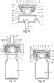
- top, bottom, “upper” and “lower” refer to the upright position of the device as shown in the Figures 11 and 12 .
- the reservoir 1 may in particular be in the form of a bottle.
- the reservoir 1 contains a fluid product, in particular of the pharmaceutical type.
- a closure device is fixed to the neck 2 of the tank 1.
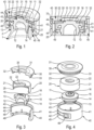
- This closure device comprises a cap 10, a fixing ring 20, a cover 30 and a blocking element 40.
- the plug 10 intended to seal the tank 1 in a sealed manner is preferably made of elastically deformable material, such as for example rubber or any other suitable elastomeric material.
- This plug 10 comprises a radial plate 11 and an approximately cylindrical axial barrel 12. In the sealing position, the axial barrel 12 penetrates inside said neck 2.
- the cap 10 includes sealing means for achieving sealing with the tank.
- the axial barrel 12 comprises on its external surface at least one peripheral sealing bead 13 which cooperates with the interior of the neck 2 of the tank 1 to guarantee the sealed sealing of the tank.
- the radial plate 11 has an external diameter greater than the external diameter of the axial barrel 12, and comprises at its radially outer edge an annular projection 14 extending downwards.
- this annular projection 14 will deform and provide a certain spring effect as well as dimensional compensation, to optimize the assembly and/or the sealing in the assembled state.
- the annular projection 14 is peripheral and is, during the assembly of the closure device on the neck 2 of the tank 1, crushed on the upper axial edge 3 of said neck 2 to achieve sealing with the tank 1.
- the sealing bead 13 is no longer obligatory, and could either be completely omitted, or replaced by several parts of beads separated from each other and distributed on the periphery of the axial barrel 12, without sealing function.
- the radial plate 11 comprises a tapping zone 15 intended to be pierced by a suitable device, such as a syringe, to collect all or part of the fluid product contained in the reservoir 1.
- This tapping zone 15 is preferably central and defined inside an axial ring 16, as visible in particular in the figure.
- the radially external edge of said axial ring 16 is slightly conical, flaring upwards.
- the internal surface of the cap 10 which comes into contact with the fluid product contained in the reservoir 1 may be covered with a coating, in particular a thin film of ETFE (ethylene tetrafluoroethylene), in order to limit the interactions between the cap 10 and the fluid product.
- a coating in particular a thin film of ETFE (ethylene tetrafluoroethylene), in order to limit the interactions between the cap 10 and the fluid product.
- ETFE ethylene tetrafluoroethylene
- the fixing ring 20 is provided for fixing and holding the cap 10 on the neck 2 of the tank 1.
- This fixing ring 20 comprises a cylindrical axial sleeve 21 provided on the upper side with a radial flange 22 extending radially inwards and comprising a central opening 23.
- said radial flange 22 is positioned on the radial plate 11 of the plug 10, with the opening 23 receiving the axial ring 16 and the tapping zone 15 of the plug 10.
- the radial edge of said central opening 23 snaps onto the radially external edge of said axial ring 16 when the latter is slightly conical.
- the cylindrical axial sleeve 21 comprises first fixing means 25, in particular by snap-fastening, for fixing to the neck 2 of the tank 1.
- first fixing means 25 comprise a radial profile extending radially inwards. In the example shown, this radial profile is peripheral, but it could alternatively comprise several lugs distributed around the periphery. Other means of fixing to the neck 2 of the tank 1 are also conceivable.
- the cover 30 comprises a radial disc 31 which, in the assembled state, is positioned on the upper surface of the radial flange 22 of the fixing ring 20, as visible in particular on the Figures 1 and 2 .
- the cover 30 also comprises a cylindrical axial envelope 32 extending axially downward from said radial disk 31, the internal diameter of said axial envelope 32 being identical to or very slightly greater than the external diameter of the axial sleeve 21 of the fixing ring 20.
- said axial envelope 32 is positioned around the axial sleeve 21 with little or no play between them.
- the axial envelope 32 only extends over a small part of the height of the axial sleeve 21.
- the axial envelope 32 comprises second fixing means 33, such as one or more projections extending radially outwards, which will be described in more detail below. These second fixing means 33 are advantageously provided at the level of the lower axial edge of the axial envelope 32.
- the lower surface of the radial disk 31 comprises a central recess 35 delimited by an annular axial projection 36, said central recess 35 being found in the assembled state above the tapping zone 15 of the plug 10.
- the annular axial projection 36 is connected to the axial envelope 32 by a plurality of radial bridges 37 distributed around the periphery. In this implementation, it is therefore the annular axial projection 36 and the radial bridges 37 which are, in the assembled state, in contact with the upper surface of the radial flange 22 of the fixing ring 20.
- the locking element 40 comprises a cylindrical axial wall 41 whose internal diameter is greater than the external diameter of the axial casing 32 and that of the second fixing means 33 of the cover 30.
- the axial wall 41 comprises complementary fixing means 43, advantageously at its upper axial edge.
- these complementary fixing means comprise one or more profiles 43 extending radially inwards, with the internal diameter of said profiles 43 which is identical to or slightly greater than the external diameter of the axial casing 32 but less than the external diameter of the projections 33 of the cover 30.
- the profiles 43 of the locking element 40 snap onto the projection(s) 33 of the cover 30.
- the external shape of the profiles 43 and projections 33 can be produced in a conventional manner, with inclined planes sliding on each other during the assembly phase, and radial surfaces forming snap-fastening stops after assembly.
- the cover 30 comprises several separate projections 33, for example two or three, distributed over the periphery, but a single projection 33 extending radially outwards over the entire periphery would also be conceivable.
- the blocking element 40 comprises a single profile 43 extending radially inwards around the entire periphery, but several separate profiles 43 distributed around the periphery would also be conceivable.
- the second fastening means 33 of the cover 30 and the complementary fastening means 43 of the blocking element 40 could be made differently, without necessarily forming a snap-fastening.
- the cover 30 and the blocking element 40 then form a unitary subassembly.
- Other alternative fastenings are also possible.
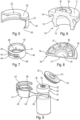
- the axial wall 41 comprises on a portion of its periphery a tearable tab 42 defined between two grooves 44, 45 which form bridges of thin material.
- This tab 42 comprises a gripping portion 46 which the user can grasp to tear the tab on a portion of the periphery of the locking element 40.
- the tearable tab 42 ends on the side opposite the gripping part 46 by a flared part 42', so that at the end of tearing, the axial wall 41 opens over its entire height, thus allowing the blocking element 40 to be removed from the sealing device.
- said axial wall 41 On its lower axial edge, said axial wall 41 comprises an annular radial wall 49 extending radially inwards.
- the radially inner edge of said annular radial wall 49 has a diameter smaller than the outer diameter of the cylindrical axial sleeve 21 of the fixing ring 20.
- this annular radial wall 49 In the assembled state, this annular radial wall 49 is positioned axially under said cylindrical axial sleeve 21, thus preventing removal of the locking element 40 by upward axial traction.
- the radially inner edge of the annular radial wall 49 also has a diameter smaller than the outer diameter of the tank 1.
- the cap 10 In the assembled state of the closure device, the cap 10 seals with the neck 2 of the tank 1, the fixing ring 20 fixes and maintains said cap 10 in its sealed closure position, the cover 30 protects the cap 10 and prevents access to its tapping zone 15, and the element of locking device 40 prevents the removal of the cover 30 while being held in the locking position on the one hand by the snap-fastening with the cover 30 and on the other hand by the axial locking provided by the fixing ring 20 at the annular radial wall 49.
- the shutter device In the assembled state, the shutter device therefore forms a non-dismountable subassembly.
- the fixing ring 20 is first assembled on the plug 10, advantageously with a snap-fastening of one on the other at the central opening 23. Then, in the example of the figure 10 , the cover 30 is assembled on the fixing ring 20 from above, and then the locking element 40 snaps into place from below on the cover 30, according to the arrow F1.
- the cap-fixing ring unit can first be arranged in the locking element 40, and then the cover 30 can be snapped into place from above.
- the assembly of the cover 30 and the locking element 40 around the cap-fixing ring unit can be done in a single step, the cap-fixing ring unit then being sandwiched between the cover 30 and the locking element 40.
- the assembly of the closure device on the neck 2 of the tank 1 is advantageously done by axially pushing the closure device downwards, according to the arrow F2 on the figure 11 .
- the presence of the central recess 35 in the cover 30 ensures that during assembly, the entire force F2 exerted on the cover 30 is transmitted to the fixing ring 20, without direct interaction between the cover 30 and the plug 10.
- said at least one sealing bead 13 are chosen such that the sealing is guaranteed in the assembled state, without generating excessive forces during assembly. This makes it possible to use an assembly machine with baskets or nests capable of simultaneously assembling several dozen devices, for example a hundred.
- the closure device After assembly of the closure device on the tank, the closure device includes a tamper-proof first-use indicator. Indeed, as long as the tear-off tab 42 is not torn, and the blocking element 40 removed, the cover 30 cannot be removed. The contents of the tank are therefore perfectly protected. After removal of the blocking element 40, the cover 30 can also be removed. On the other hand, it is then no longer possible to replace another blocking element 40, because this assembly must necessarily be done before assembly on the tank 1. Indeed, the internal diameter of the annular radial wall 49 being less than the external diameter of the tank 1, it is not possible to assemble a blocking element 40 over the tank 1. Similarly, the internal diameter of the annular radial wall 49 being less than the external diameter of the cylindrical axial sleeve 21 of the fixing ring 20, it is not possible to assemble a blocking element 40 over the fixing ring 20.
Landscapes
- Engineering & Computer Science (AREA)
- Mechanical Engineering (AREA)
- Closures For Containers (AREA)
- Supply Devices, Intensifiers, Converters, And Telemotors (AREA)
Claims (16)
- Vorrichtung zum Abdichten eines Behälters für flüssige Produkte (1) mit einem Hals (2), der mit einem oberen axialen Rand (3) versehen ist, wobei die Vorrichtung zum Abdichten Folgendes aufweist:- einen Stopfen (10) mit einer radialen Platte (11) und einem axialen Schaft (12), wobei der axiale Schaft (12) beim Zusammenbauen in das Innere des Halses (2) eindringt, wobei der Stopfen (10) Dichtmittel (13, 14) aufweist, um eine Abdichtung mit dem Behälter (1) herzustellen,- einen Befestigungsring (20) zum Befestigen des Stopfens (10) an dem Hals (2), wobei der Befestigungsring (20) eine zylindrische axiale Hülse (21) aufweist, die an der Oberseite mit einem radialen Flansch (22) versehen ist, der sich radial nach innen erstreckt und eine zentrale Öffnung (23) aufweist, wobei die zylindrische axiale Hülse (21) an der Unterseite erste Befestigungsmittel (25) zum Befestigen an dem Hals (2) des Behälters (1) aufweist,- einen Deckel (30) mit einer radialen Scheibe (31) und einem zylindrischen axialen Mantel (32), der sich von der radialen Scheibe (31) axial nach unten erstreckt, wobei der Deckel (30) zweite Befestigungsmittel (33) aufweist,- ein Blockierelement (40) mit einer zylindrischen axialen Wand (41) und komplementären Befestigungsmitteln (43), die im zusammengebauten Zustand mit den zweiten Befestigungsmitteln (33) des Deckels (30) zusammenwirken,dadurch gekennzeichnet, dass die axiale Wand (41) auf einem Teil ihres Umfangs eine zerreißbare Zunge (42) aufweist, die zwischen zwei Nuten (44, 45) definiert ist, die Materialbrücken mit geringer Dicke bilden, wobei die Zunge (42) auf einer Seite einen Greifabschnitt (46) aufweist und auf der gegenüberliegenden Seite in einem aufgeweiteten Abschnitt (42') endet, so dass am Ende des Zerreißens die axiale Wand (41) über ihre gesamte Höhe geöffnet wird, wodurch das Blockierelement (40) der Vorrichtung zum Abdichten entfernt werden kann.
- Vorrichtung nach Anspruch 1, wobei der axiale Schaft (12) des Stopfens (10) auf seiner Außenfläche mindestens einen Dichtungswulst (13) aufweist, der mit der Innenseite des Halses (2) des Behälters (1) zusammenwirkt, um das dichte Verschließen des Behälters zu gewährleisten.
- Vorrichtung nach Anspruch 1 oder 2, wobei die radiale Platte (11) des Stopfens (10) einen Außendurchmesser hat, der größer ist als der Außendurchmesser des axialen Schafts (12), und mindestens einen sich nach unten erstreckenden ringförmigen Vorsprung (14) aufweist, der in der Abdichtposition mit dem oberen axialen Rand (3) des Halses (2) zusammenwirkt.
- Vorrichtung nach Anspruch 3, wobei der ringförmige Vorsprung (14) peripher ist und beim Zusammenbauen der Vorrichtung zum Abdichten auf dem Hals (2) des Behälters (1) auf den oberen axialen Rand (3) des Halses (2) gequetscht wird, um eine Abdichtung mit dem Behälter (1) herzustellen.
- Vorrichtung nach einem der vorhergehenden Ansprüche, wobei die radiale Platte (11) einen zentralen Einstichbereich (15) aufweist, der innerhalb eines axialen Rings (16) definiert ist.
- Vorrichtung nach Anspruch 5, wobei der radial äußere Rand des axialen Rings (16) sich nach oben hin konisch erweitert.
- Vorrichtung nach Anspruch 5 oder 6, wobei im zusammengebauten Zustand der Vorrichtung zum Abdichten der radiale Flansch (22) des Befestigungsrings (20) auf der radialen Platte (11) des Stopfens (10) positioniert ist, wobei die zentrale Öffnung (23) den axialen Ring (16) und den Einstichbereich (15) des Stopfens (10) aufnimmt.
- Vorrichtung nach Anspruch 7, wobei der radiale Rand der zentralen Öffnung (23) an der radial äußeren konischen Kante des axialen Rings (16) einrastet.
- Vorrichtung nach einem der vorhergehenden Ansprüche, wobei die ersten Befestigungsmittel (25) des Befestigungsrings (20) Einrastmittel sind, die mindestens ein radial nach innen verlaufendes Radialprofil aufweisen.
- Vorrichtung nach Anspruch 9, wobei die ersten Befestigungsmittel (25) ein einziges radiales Profil aufweisen, das sich über den gesamten Umfang der zylindrischen axialen Hülse (21) erstreckt.
- Vorrichtung nach einem der vorhergehenden Ansprüche, wobei der Innendurchmesser des axialen Mantels (32) des Deckels (30) gleich oder nur geringfügig größer ist als der Außendurchmesser der axialen Hülse (21) des Befestigungsrings (20), so dass im zusammengebauten Zustand der Vorrichtung zum Abdichten der axiale Mantel (32) um die axiale Hülse (21) herum mit keinem oder nur geringem Spiel dazwischen positioniert ist.
- Vorrichtung nach einem der vorhergehenden Ansprüche, wobei die zweiten Befestigungsmittel (33) des Deckels (30) einen oder mehrere Vorsprünge aufweisen, die sich radial nach außen erstrecken.
- Vorrichtung nach Anspruch 12, wobei die komplementären Befestigungsmittel (43) des Blockierelements (40) ein oder mehrere Profile aufweisen, die sich radial nach innen erstrecken, wobei die Profile an dem einen oder den mehreren Vorsprüngen einrasten, die die zweiten Befestigungsmittel (33) des Deckels (30) bilden.
- Vorrichtung nach einem der vorhergehenden Ansprüche, wobei die axiale Wand (41) des Blockierelements (40) an ihrem unteren axialen Rand eine ringförmige radiale Wand (49) aufweist, die sich radial nach innen erstreckt, wobei der radial innere Rand der ringförmigen radialen Wand (49) einen Durchmesser aufweist, der kleiner als der Außendurchmesser der zylindrischen axialen Hülse (21) des Befestigungsrings (20) und kleiner als der Außendurchmesser des Behälters (1) ist.
- Vorrichtung nach einem der vorhergehenden Ansprüche, wobei die Vorrichtung metallfrei ist.
- Anordnung mit einem Behälter (1) für flüssige Produkte, der einen Hals (2) und eine Vorrichtung zum Abdichten (10) nach einem der vorhergehenden Ansprüche aufweist, um einen Stopfen (10) auf dem Hals (2) zu befestigen und zu halten.
Applications Claiming Priority (2)
| Application Number | Priority Date | Filing Date | Title |
|---|---|---|---|
| FR2101797A FR3120059B1 (fr) | 2021-02-24 | 2021-02-24 | Dispositif d'obturation d'un réservoir de produit fluide |
| PCT/FR2022/050320 WO2022180337A1 (fr) | 2021-02-24 | 2022-02-22 | Dispositif d'obturation d'un reservoir de produit fluide |
Publications (2)
| Publication Number | Publication Date |
|---|---|
| EP4298028A1 EP4298028A1 (de) | 2024-01-03 |
| EP4298028B1 true EP4298028B1 (de) | 2024-12-04 |
Family
ID=75278257
Family Applications (1)
| Application Number | Title | Priority Date | Filing Date |
|---|---|---|---|
| EP22710679.6A Active EP4298028B1 (de) | 2021-02-24 | 2022-02-22 | Vorrichtung zum abdichten eines behälters für flüssige produkte |
Country Status (11)
| Country | Link |
|---|---|
| US (1) | US12486083B2 (de) |
| EP (1) | EP4298028B1 (de) |
| JP (1) | JP2024510116A (de) |
| KR (1) | KR20230150987A (de) |
| CN (1) | CN117136161A (de) |
| DK (1) | DK4298028T3 (de) |
| ES (1) | ES3002727T3 (de) |
| FR (1) | FR3120059B1 (de) |
| HU (1) | HUE070681T2 (de) |
| PL (1) | PL4298028T3 (de) |
| WO (1) | WO2022180337A1 (de) |
Families Citing this family (4)
| Publication number | Priority date | Publication date | Assignee | Title |
|---|---|---|---|---|
| IT202100003191A1 (it) * | 2021-02-12 | 2022-08-12 | Bisio Progetti Spa | Elemento di tenuta in gomma per un dispositivo di chiusura in plastica per farmaci somministrabili per via parenterale |
| FR3120059B1 (fr) * | 2021-02-24 | 2023-06-02 | Aptar France Sas | Dispositif d'obturation d'un réservoir de produit fluide |
| EP4410700B1 (de) * | 2023-02-06 | 2025-09-03 | UAB Baltic caps | Flaschenverschluss |
| WO2024219892A1 (ko) * | 2023-04-20 | 2024-10-24 | 오스템임플란트 주식회사 | 바이알 앰플용 캡 어셈블리 |
Family Cites Families (67)
| Publication number | Priority date | Publication date | Assignee | Title |
|---|---|---|---|---|
| US2734649A (en) * | 1956-02-14 | Moistureproof vial closure | ||
| US2444779A (en) * | 1946-04-06 | 1948-07-06 | Krasberg Rudolf | Bottle cap |
| US2950834A (en) * | 1957-10-28 | 1960-08-30 | Ralph O Mazza | Pressure retaining stopper |
| US3109547A (en) * | 1960-03-04 | 1963-11-05 | Permuta Closures Ltd | Bottle closures |
| GB1028972A (en) * | 1962-02-01 | 1966-05-11 | Permuta Closures Ltd | Improvements in or relating to closures for bottles |
| US3338446A (en) * | 1966-09-26 | 1967-08-29 | Black Mtn Spring Water | Plastic cap and bottle neck |
| US3792794A (en) * | 1971-10-04 | 1974-02-19 | Cutter Lab | Closure for containers |
| US3913772A (en) * | 1973-09-14 | 1975-10-21 | Anchor Hocking Corp | Tamperproof closure cap and sealed package |
| US3946891A (en) * | 1975-04-07 | 1976-03-30 | Picoy Anthony R | Safety cap for pressurized bottles |
| US4032029A (en) * | 1976-04-05 | 1977-06-28 | Benjamin Arthur Cochrane | Tamper-proof bottle cap and container |
| US4037746A (en) * | 1976-06-11 | 1977-07-26 | Gsf Corporation | Plastic cap and bottle neck |
| US4149647A (en) * | 1976-08-27 | 1979-04-17 | Gebruder Seidel Kg | Metal tear off cap |
| US4166552A (en) * | 1977-11-16 | 1979-09-04 | Three Sisters Ranch Enterprises | Plastic cap and container construction |
| US4251003A (en) * | 1979-01-19 | 1981-02-17 | Toni Casutt | Bottle closing device |
| JPS59183864U (ja) * | 1983-05-25 | 1984-12-07 | 吉田工業株式会社 | 容器のシ−ル付中栓 |
| US4471879A (en) * | 1983-08-04 | 1984-09-18 | The West Company | Metal overcap for pharmaceutical and similar containers |
| US4506797A (en) * | 1983-09-19 | 1985-03-26 | Three Sisters Ranch Enterprises | Wine bottle cover |
| US4474302A (en) * | 1983-11-03 | 1984-10-02 | James R. Goldberg | Safety champagne cork |
| DE3473866D1 (en) * | 1983-12-01 | 1988-10-13 | Johnsen Jorgensen Plastics Ltd | A child resistant and tamper-resistant container and closure assembly |
| GB8527598D0 (en) * | 1985-11-08 | 1985-12-11 | Metal Closures Group Plc | Capsules |
| US4784279A (en) * | 1987-07-31 | 1988-11-15 | The West Company | Present invention relates to improvements in tamper-proof closures |
| US5052574A (en) * | 1990-02-16 | 1991-10-01 | Cardinal Packaging Inc. | Tamper-proof and tamper-evident container closure system |
| US5269429A (en) * | 1990-05-15 | 1993-12-14 | Robert Finke Gmbh & Co. Kg | Closure cap for infusion or transfusion bottles |
| US5085332B1 (en) * | 1991-04-11 | 1994-04-05 | Gettig Technologies Inc | Closure assembly |
| DE9105168U1 (de) * | 1991-04-26 | 1991-06-20 | Pharma-Gummi Wimmer West Gmbh, 5180 Eschweiler | Flaschenverschluß |
| US5314084A (en) * | 1992-08-21 | 1994-05-24 | The West Company, Incorporated | Two piece all plastic seal |
| US5373954A (en) * | 1993-03-19 | 1994-12-20 | Sunbeam Plastics Corporation | Tamper indicating closure |
| FR2822810B1 (fr) * | 2001-03-28 | 2003-08-22 | Rical Sa | Dispositif de bouchage pour une bonbonne, munie de moyens de retenue et d'accorchage d'un joint coule ou moule, et procede de realisation |
| EP1487712B1 (de) * | 2002-01-11 | 2006-10-25 | Bericap Holding GmbH | Geschlossen herstellbarer kunststoffverschluss, sowie spritzgussform und verfahren zu dessen herstellung |
| US20050086830A1 (en) * | 2003-10-24 | 2005-04-28 | Zukor Kenneth S. | Processing cap assembly for isolating contents of a container |
| ES2330150T3 (es) * | 2005-11-30 | 2009-12-04 | Biocorp Recherche Et Developpement | Dispositivo de taponado para un recipiente y recipiente equipado con dicho dispositivo. |
| CL2007002373A1 (es) * | 2006-08-17 | 2008-01-11 | Zork Pty Ltd | Un cierre de botella para botellas que contienen liquidos a alta presion,con el cierre teniendo una primera parte y una segunda parte,donde la primera parte tiene una porcion adaptada para recibir una porcion de una seccion superior de un cuello de botella,y una segunda parte que encaja sobre la primera parte. |
| FR2912384B1 (fr) * | 2007-02-09 | 2009-04-10 | Biocorp Rech Et Dev Sa | Dispositif de bouchage pour un recipient, recipient equipe d'un tel dispositif et procede de fermeture d'un lot de tel recipient |
| FR2927316B1 (fr) * | 2008-02-11 | 2010-05-14 | Biocorp Rech Et Dev | Dispositif de bouchage a chapeau d'appui et recipient equipe d'un tel dispositif |
| FR2945283B1 (fr) * | 2009-05-06 | 2015-06-26 | Valois Sas | Dispositif de fixation pour fixer une pompe sur un col de reservoir |
| WO2010131100A1 (en) * | 2009-05-13 | 2010-11-18 | Pt. Aqua Golden Mississippi Tbk. | Container lid of multicolor injection |
| FR2950035B1 (fr) * | 2009-09-15 | 2011-09-02 | Raymond A & Cie | Coiffe de verrouillage pour recipient a col |
| FR2950865B1 (fr) * | 2009-10-01 | 2011-10-28 | Raymond A & Cie | Coiffe de verrouillage pour recipient a col avec une capsule a pattes de fixation |
| JP5566765B2 (ja) * | 2010-04-30 | 2014-08-06 | 大和特殊硝子株式会社 | バイアル用栓体 |
| EP2383199B1 (de) * | 2010-04-30 | 2013-06-12 | Sumitomo Rubber Industries, Ltd. | Verschlussvorrichtung für einen Behälter und Dichtungselement für die Vorrichtung |
| FR2967656B1 (fr) * | 2010-11-24 | 2012-12-07 | Biocorp Rech Et Dev | Dispositif de bouchage d'un recipient et recipient equipe d'un tel dispositif |
| WO2013045619A1 (en) * | 2011-09-29 | 2013-04-04 | Ge Healthcare As | Package |
| AP3940A (en) * | 2012-02-02 | 2016-12-16 | Becton Dickinson Holdings Pte Ltd | Adaptor for coupling with a medical container |
| SG192310A1 (en) * | 2012-02-02 | 2013-08-30 | Becton Dickinson Holdings Pte Ltd | Adaptor for coupling to a medical container |
| FR2986782B1 (fr) * | 2012-02-13 | 2014-03-07 | Raymond A & Cie | Dispositif de verrouillage de bouchon sur recipient a collerette, recipient a collerette obture par bouchon pourvu d'un tel dispositif de verrouillage |
| EP2842884A1 (de) * | 2013-08-27 | 2015-03-04 | F. Hoffmann-La Roche AG | Kappe für einen Container |
| EP3042862B1 (de) * | 2013-09-02 | 2018-10-17 | Taisei Kako Co., Ltd. | Kappe für phiolen |
| ITMI20132005A1 (it) * | 2013-12-02 | 2015-06-03 | Antonio Mutterle | Complesso di chiusura per flacone, relativo flacone e metodo di assemblaggio |
| HUE041829T2 (hu) * | 2014-06-18 | 2019-05-28 | Altergon Sa | Palack lezárására szolgáló eljárás, valamint a kapcsolódó lezárt palack |
| FR3027700B1 (fr) * | 2014-10-27 | 2018-01-19 | Les Bouchages Delage | Procede d'authentification de l'ensemble de fermeture d'un recipient |
| JP6882197B2 (ja) * | 2015-06-29 | 2021-06-02 | アントニオ ミュッターレMUTTERLE, Antonio | ボトル用の密閉アセンブリ、関連するボトルおよび組立て方法 |
| DE102017127313A1 (de) * | 2017-11-20 | 2019-05-23 | Bericap Holding Gmbh | Kunststoffverschluss für Behälter |
| CN112004756B (zh) * | 2018-01-19 | 2021-11-19 | 西部制药服务有限公司(德国) | 封堵装置 |
| US10899510B2 (en) * | 2018-10-17 | 2021-01-26 | Nicole Thomas | Vial assembly with cap with disinfectant and related methods |
| JP7561434B2 (ja) * | 2019-07-02 | 2024-10-04 | 大成化工株式会社 | キャップ及びキャップ付バイアル |
| FR3098505B1 (fr) * | 2019-07-09 | 2021-06-04 | A Raymond Et Cie | coiffe de verrouillage sécable pour récipient à col |
| FR3098504B1 (fr) * | 2019-07-09 | 2021-06-04 | A Raymond Et Cie | coiffe de verrouillage pour récipient à col |
| FR3106339B1 (fr) * | 2020-01-16 | 2021-12-24 | A Raymond Et Cie | Coiffe de verrouillage pour recipient a col avec une capsule a pattes de fixation secables |
| JP2023554050A (ja) * | 2020-12-17 | 2023-12-26 | エフ・ホフマン-ラ・ロシュ・アクチェンゲゼルシャフト | 閉鎖システムおよびキット |
| EP4268786A4 (de) * | 2020-12-25 | 2024-08-14 | Daikyo Seiko, LTD. | Kunststoffkappe |
| JP7386579B2 (ja) * | 2020-12-25 | 2023-11-27 | 株式会社大協精工 | プラスチック製アダプタ及び閉鎖式薬物搬送システム |
| EP4268787A4 (de) * | 2020-12-25 | 2024-08-14 | Daikyo Seiko, LTD. | Kunststoffkappe und vorrichtung zur übertragung eines geschlossenen systems |
| IT202100003182A1 (it) * | 2021-02-12 | 2022-08-12 | Bisio Progetti Spa | Dispositivo di chiusura in plastica per un contenitore per prodotti farmaceutici per via parenterale |
| FR3120059B1 (fr) * | 2021-02-24 | 2023-06-02 | Aptar France Sas | Dispositif d'obturation d'un réservoir de produit fluide |
| JP2024515702A (ja) * | 2021-04-26 | 2024-04-10 | コーニング インコーポレイテッド | 低い貯蔵温度でシール完全性を維持するための容器施栓系および密閉アセンブリ |
| US11767152B2 (en) * | 2021-06-29 | 2023-09-26 | Iv Thought Products And Design Corp. | Re-sealing vacuum package receptacle |
| EP4190303A1 (de) * | 2021-12-01 | 2023-06-07 | Wirthwein Medical GmbH & Co. KG | Medikamentenbehälter |
-
2021
- 2021-02-24 FR FR2101797A patent/FR3120059B1/fr active Active
-
2022
- 2022-02-22 KR KR1020237032640A patent/KR20230150987A/ko active Pending
- 2022-02-22 DK DK22710679.6T patent/DK4298028T3/da active
- 2022-02-22 PL PL22710679.6T patent/PL4298028T3/pl unknown
- 2022-02-22 WO PCT/FR2022/050320 patent/WO2022180337A1/fr not_active Ceased
- 2022-02-22 JP JP2023550217A patent/JP2024510116A/ja active Pending
- 2022-02-22 CN CN202280028404.4A patent/CN117136161A/zh active Pending
- 2022-02-22 EP EP22710679.6A patent/EP4298028B1/de active Active
- 2022-02-22 US US18/278,475 patent/US12486083B2/en active Active
- 2022-02-22 HU HUE22710679A patent/HUE070681T2/hu unknown
- 2022-02-22 ES ES22710679T patent/ES3002727T3/es active Active
Also Published As
| Publication number | Publication date |
|---|---|
| US12486083B2 (en) | 2025-12-02 |
| US20240132257A1 (en) | 2024-04-25 |
| FR3120059A1 (fr) | 2022-08-26 |
| US20240228125A9 (en) | 2024-07-11 |
| FR3120059B1 (fr) | 2023-06-02 |
| KR20230150987A (ko) | 2023-10-31 |
| CN117136161A (zh) | 2023-11-28 |
| PL4298028T3 (pl) | 2025-04-07 |
| HUE070681T2 (hu) | 2025-06-28 |
| EP4298028A1 (de) | 2024-01-03 |
| ES3002727T3 (en) | 2025-03-07 |
| DK4298028T3 (da) | 2025-01-02 |
| JP2024510116A (ja) | 2024-03-06 |
| WO2022180337A1 (fr) | 2022-09-01 |
Similar Documents
| Publication | Publication Date | Title |
|---|---|---|
| EP4298028B1 (de) | Vorrichtung zum abdichten eines behälters für flüssige produkte | |
| EP0850178B1 (de) | Vorrichtung mit originalitätssicherung zum anschluss an einen geschlossenen behälter | |
| EP0244327B1 (de) | Behältermundstück mit Mitteln zum Verhindern des Wiederfüllens nach der Entleerung des ursprünglichen Inhaltes | |
| EP0684187B1 (de) | Ausgiesskappe mit Garantieverschluss | |
| EP0119145B1 (de) | Verschlussvorrichtung eines Behälters mit verengter Öffnung und Verschlusskappe | |
| EP0475789A1 (de) | Vorrichtung zur getrennten Aufbewahrung wenigstens zweier Produkte und zum Mischen derselben beim ersten Gebrauch | |
| FR2612159A1 (fr) | Emballage a recipient et bouchon verseur de securite | |
| FR2612495A1 (fr) | Emballage verseur de securite | |
| CH624632A5 (de) | ||
| FR2806070A1 (fr) | Procede et dispositif de bouchage d'un recipient et recipient pourvu d'un tel dispositif | |
| EP3892584B1 (de) | Verschlusskappe für einen behälter mit einem gewindehals, der geeignet ist zur verwendung in einem geschlossenen transfersystem | |
| FR2543113A1 (fr) | Fermeture de recipient a diaphragme d'etancheite dechirable protege en flexion | |
| EP2007642A1 (de) | Behälterverschluss, damit versehener behälter und herstellungsverfahren dafür | |
| FR3106339A1 (fr) | Coiffe de verrouillage pour recipient a col avec une capsule a pattes de fixation secables | |
| EP1751023B1 (de) | Verteilvorrichtung für parfum | |
| EP1565273A1 (de) | Befestigungsvorrichtung und diese enthaltender spender | |
| EP0953513B1 (de) | Verpackung aus Metall mit Sicherheitskappe | |
| WO1999000308A1 (fr) | Ensemble verseur a bouchage a vis pour un recipient | |
| FR2745794A1 (fr) | Dispositif de bouchage pour un recipient tel qu'en particulier un flacon a usage medical | |
| FR2779702A1 (fr) | Dispositif de bouchage a vis de type inviolable | |
| FR2745793A1 (fr) | Dispositif de bouchage pour un recipient tel qu'en particulier un flacon a usage medical | |
| FR2748260A1 (fr) | Dispositif de bouchage inviolable pour un recipient tel qu'en particulier une bouteille ou un flacon | |
| EP3590864A1 (de) | Verschlussvorrichtung eines behälters, verschlussstopfen dieser vorrichtung und einheit, dieaus dem behälter und der verschlussvorrichtung besteht | |
| EP0615918B1 (de) | Hermetischer Verschluss für Behälter | |
| EP3196142B1 (de) | Behälter und stöpsel zum befestigen durch festklicken auf seinem hals |
Legal Events
| Date | Code | Title | Description |
|---|---|---|---|
| STAA | Information on the status of an ep patent application or granted ep patent |
Free format text: STATUS: UNKNOWN |
|
| STAA | Information on the status of an ep patent application or granted ep patent |
Free format text: STATUS: THE INTERNATIONAL PUBLICATION HAS BEEN MADE |
|
| PUAI | Public reference made under article 153(3) epc to a published international application that has entered the european phase |
Free format text: ORIGINAL CODE: 0009012 |
|
| STAA | Information on the status of an ep patent application or granted ep patent |
Free format text: STATUS: REQUEST FOR EXAMINATION WAS MADE |
|
| 17P | Request for examination filed |
Effective date: 20230920 |
|
| AK | Designated contracting states |
Kind code of ref document: A1 Designated state(s): AL AT BE BG CH CY CZ DE DK EE ES FI FR GB GR HR HU IE IS IT LI LT LU LV MC MK MT NL NO PL PT RO RS SE SI SK SM TR |
|
| P01 | Opt-out of the competence of the unified patent court (upc) registered |
Effective date: 20240207 |
|
| DAV | Request for validation of the european patent (deleted) | ||
| DAX | Request for extension of the european patent (deleted) | ||
| REG | Reference to a national code |
Ref legal event code: R079 Ref country code: DE Ref legal event code: R079 Ref document number: 602022008428 Country of ref document: DE Free format text: PREVIOUS MAIN CLASS: B65D0051000000 Ipc: B65D0055080000 |
|
| GRAP | Despatch of communication of intention to grant a patent |
Free format text: ORIGINAL CODE: EPIDOSNIGR1 |
|
| STAA | Information on the status of an ep patent application or granted ep patent |
Free format text: STATUS: GRANT OF PATENT IS INTENDED |
|
| RIC1 | Information provided on ipc code assigned before grant |
Ipc: B65D 55/08 20060101AFI20240613BHEP |
|
| INTG | Intention to grant announced |
Effective date: 20240702 |
|
| GRAS | Grant fee paid |
Free format text: ORIGINAL CODE: EPIDOSNIGR3 |
|
| GRAA | (expected) grant |
Free format text: ORIGINAL CODE: 0009210 |
|
| STAA | Information on the status of an ep patent application or granted ep patent |
Free format text: STATUS: THE PATENT HAS BEEN GRANTED |
|
| AK | Designated contracting states |
Kind code of ref document: B1 Designated state(s): AL AT BE BG CH CY CZ DE DK EE ES FI FR GB GR HR HU IE IS IT LI LT LU LV MC MK MT NL NO PL PT RO RS SE SI SK SM TR |
|
| REG | Reference to a national code |
Ref country code: CH Ref legal event code: EP |
|
| REG | Reference to a national code |
Ref country code: DE Ref legal event code: R096 Ref document number: 602022008428 Country of ref document: DE |
|
| REG | Reference to a national code |
Ref country code: IE Ref legal event code: FG4D Free format text: LANGUAGE OF EP DOCUMENT: FRENCH |
|
| REG | Reference to a national code |
Ref country code: DK Ref legal event code: T3 Effective date: 20241219 |
|
| REG | Reference to a national code |
Ref country code: NL Ref legal event code: FP |
|
| PGFP | Annual fee paid to national office [announced via postgrant information from national office to epo] |
Ref country code: NL Payment date: 20250128 Year of fee payment: 4 |
|
| REG | Reference to a national code |
Ref country code: SE Ref legal event code: TRGR |
|
| REG | Reference to a national code |
Ref country code: ES Ref legal event code: FG2A Ref document number: 3002727 Country of ref document: ES Kind code of ref document: T3 Effective date: 20250307 |
|
| REG | Reference to a national code |
Ref country code: LT Ref legal event code: MG9D |
|
| PG25 | Lapsed in a contracting state [announced via postgrant information from national office to epo] |
Ref country code: HR Free format text: LAPSE BECAUSE OF FAILURE TO SUBMIT A TRANSLATION OF THE DESCRIPTION OR TO PAY THE FEE WITHIN THE PRESCRIBED TIME-LIMIT Effective date: 20241204 |
|
| PGFP | Annual fee paid to national office [announced via postgrant information from national office to epo] |
Ref country code: DE Payment date: 20250212 Year of fee payment: 4 |
|
| PG25 | Lapsed in a contracting state [announced via postgrant information from national office to epo] |
Ref country code: FI Free format text: LAPSE BECAUSE OF FAILURE TO SUBMIT A TRANSLATION OF THE DESCRIPTION OR TO PAY THE FEE WITHIN THE PRESCRIBED TIME-LIMIT Effective date: 20241204 |
|
| PGFP | Annual fee paid to national office [announced via postgrant information from national office to epo] |
Ref country code: DK Payment date: 20250130 Year of fee payment: 4 |
|
| PG25 | Lapsed in a contracting state [announced via postgrant information from national office to epo] |
Ref country code: BG Free format text: LAPSE BECAUSE OF FAILURE TO SUBMIT A TRANSLATION OF THE DESCRIPTION OR TO PAY THE FEE WITHIN THE PRESCRIBED TIME-LIMIT Effective date: 20241204 |
|
| PGFP | Annual fee paid to national office [announced via postgrant information from national office to epo] |
Ref country code: ES Payment date: 20250317 Year of fee payment: 4 |
|
| PGFP | Annual fee paid to national office [announced via postgrant information from national office to epo] |
Ref country code: SE Payment date: 20250217 Year of fee payment: 4 Ref country code: IE Payment date: 20250117 Year of fee payment: 4 |
|
| PG25 | Lapsed in a contracting state [announced via postgrant information from national office to epo] |
Ref country code: NO Free format text: LAPSE BECAUSE OF FAILURE TO SUBMIT A TRANSLATION OF THE DESCRIPTION OR TO PAY THE FEE WITHIN THE PRESCRIBED TIME-LIMIT Effective date: 20250304 |
|
| PG25 | Lapsed in a contracting state [announced via postgrant information from national office to epo] |
Ref country code: GR Free format text: LAPSE BECAUSE OF FAILURE TO SUBMIT A TRANSLATION OF THE DESCRIPTION OR TO PAY THE FEE WITHIN THE PRESCRIBED TIME-LIMIT Effective date: 20250305 Ref country code: LV Free format text: LAPSE BECAUSE OF FAILURE TO SUBMIT A TRANSLATION OF THE DESCRIPTION OR TO PAY THE FEE WITHIN THE PRESCRIBED TIME-LIMIT Effective date: 20241204 |
|
| PGFP | Annual fee paid to national office [announced via postgrant information from national office to epo] |
Ref country code: AT Payment date: 20250417 Year of fee payment: 4 Ref country code: CH Payment date: 20250301 Year of fee payment: 4 Ref country code: BE Payment date: 20250226 Year of fee payment: 4 |
|
| PGFP | Annual fee paid to national office [announced via postgrant information from national office to epo] |
Ref country code: FR Payment date: 20250227 Year of fee payment: 4 Ref country code: PL Payment date: 20250120 Year of fee payment: 4 |
|
| PGFP | Annual fee paid to national office [announced via postgrant information from national office to epo] |
Ref country code: IT Payment date: 20250228 Year of fee payment: 4 |
|
| PG25 | Lapsed in a contracting state [announced via postgrant information from national office to epo] |
Ref country code: RS Free format text: LAPSE BECAUSE OF FAILURE TO SUBMIT A TRANSLATION OF THE DESCRIPTION OR TO PAY THE FEE WITHIN THE PRESCRIBED TIME-LIMIT Effective date: 20250304 |
|
| REG | Reference to a national code |
Ref country code: HU Ref legal event code: AG4A Ref document number: E070681 Country of ref document: HU |
|
| PG25 | Lapsed in a contracting state [announced via postgrant information from national office to epo] |
Ref country code: SM Free format text: LAPSE BECAUSE OF FAILURE TO SUBMIT A TRANSLATION OF THE DESCRIPTION OR TO PAY THE FEE WITHIN THE PRESCRIBED TIME-LIMIT Effective date: 20241204 |
|
| PG25 | Lapsed in a contracting state [announced via postgrant information from national office to epo] |
Ref country code: IS Free format text: LAPSE BECAUSE OF FAILURE TO SUBMIT A TRANSLATION OF THE DESCRIPTION OR TO PAY THE FEE WITHIN THE PRESCRIBED TIME-LIMIT Effective date: 20250404 |
|
| PGFP | Annual fee paid to national office [announced via postgrant information from national office to epo] |
Ref country code: HU Payment date: 20250121 Year of fee payment: 4 |
|
| PG25 | Lapsed in a contracting state [announced via postgrant information from national office to epo] |
Ref country code: PT Free format text: LAPSE BECAUSE OF FAILURE TO SUBMIT A TRANSLATION OF THE DESCRIPTION OR TO PAY THE FEE WITHIN THE PRESCRIBED TIME-LIMIT Effective date: 20250404 |
|
| PG25 | Lapsed in a contracting state [announced via postgrant information from national office to epo] |
Ref country code: EE Free format text: LAPSE BECAUSE OF FAILURE TO SUBMIT A TRANSLATION OF THE DESCRIPTION OR TO PAY THE FEE WITHIN THE PRESCRIBED TIME-LIMIT Effective date: 20241204 |
|
| PG25 | Lapsed in a contracting state [announced via postgrant information from national office to epo] |
Ref country code: RO Free format text: LAPSE BECAUSE OF FAILURE TO SUBMIT A TRANSLATION OF THE DESCRIPTION OR TO PAY THE FEE WITHIN THE PRESCRIBED TIME-LIMIT Effective date: 20241204 |
|
| PG25 | Lapsed in a contracting state [announced via postgrant information from national office to epo] |
Ref country code: SK Free format text: LAPSE BECAUSE OF FAILURE TO SUBMIT A TRANSLATION OF THE DESCRIPTION OR TO PAY THE FEE WITHIN THE PRESCRIBED TIME-LIMIT Effective date: 20241204 |
|
| PG25 | Lapsed in a contracting state [announced via postgrant information from national office to epo] |
Ref country code: CZ Free format text: LAPSE BECAUSE OF FAILURE TO SUBMIT A TRANSLATION OF THE DESCRIPTION OR TO PAY THE FEE WITHIN THE PRESCRIBED TIME-LIMIT Effective date: 20241204 |
|
| REG | Reference to a national code |
Ref country code: DE Ref legal event code: R097 Ref document number: 602022008428 Country of ref document: DE |
|
| PG25 | Lapsed in a contracting state [announced via postgrant information from national office to epo] |
Ref country code: MC Free format text: LAPSE BECAUSE OF FAILURE TO SUBMIT A TRANSLATION OF THE DESCRIPTION OR TO PAY THE FEE WITHIN THE PRESCRIBED TIME-LIMIT Effective date: 20241204 |
|
| PLBE | No opposition filed within time limit |
Free format text: ORIGINAL CODE: 0009261 |
|
| STAA | Information on the status of an ep patent application or granted ep patent |
Free format text: STATUS: NO OPPOSITION FILED WITHIN TIME LIMIT |
|
| PG25 | Lapsed in a contracting state [announced via postgrant information from national office to epo] |
Ref country code: LU Free format text: LAPSE BECAUSE OF NON-PAYMENT OF DUE FEES Effective date: 20250222 |
|
| 26N | No opposition filed |
Effective date: 20250905 |