EP4296983B1 - Papierblatthandhabungsvorrichtung - Google Patents
Papierblatthandhabungsvorrichtung Download PDFInfo
- Publication number
- EP4296983B1 EP4296983B1 EP21926609.5A EP21926609A EP4296983B1 EP 4296983 B1 EP4296983 B1 EP 4296983B1 EP 21926609 A EP21926609 A EP 21926609A EP 4296983 B1 EP4296983 B1 EP 4296983B1
- Authority
- EP
- European Patent Office
- Prior art keywords
- banknote
- taking
- stage
- opening
- unit
- Prior art date
- Legal status (The legal status is an assumption and is not a legal conclusion. Google has not performed a legal analysis and makes no representation as to the accuracy of the status listed.)
- Active
Links
Images


Classifications
-
- G—PHYSICS
- G07—CHECKING-DEVICES
- G07D—HANDLING OF COINS OR VALUABLE PAPERS, e.g. TESTING, SORTING BY DENOMINATIONS, COUNTING, DISPENSING, CHANGING OR DEPOSITING
- G07D11/00—Devices accepting coins; Devices accepting, dispensing, sorting or counting valuable papers
- G07D11/10—Mechanical details
- G07D11/14—Inlet or outlet ports
-
- B—PERFORMING OPERATIONS; TRANSPORTING
- B65—CONVEYING; PACKING; STORING; HANDLING THIN OR FILAMENTARY MATERIAL
- B65H—HANDLING THIN OR FILAMENTARY MATERIAL, e.g. SHEETS, WEBS, CABLES
- B65H1/00—Supports or magazines for piles from which articles are to be separated
- B65H1/02—Supports or magazines for piles from which articles are to be separated adapted to support articles on edge
- B65H1/025—Supports or magazines for piles from which articles are to be separated adapted to support articles on edge with controlled positively-acting mechanical devices for advancing the pile to present the articles to the separating device
-
- B—PERFORMING OPERATIONS; TRANSPORTING
- B65—CONVEYING; PACKING; STORING; HANDLING THIN OR FILAMENTARY MATERIAL
- B65H—HANDLING THIN OR FILAMENTARY MATERIAL, e.g. SHEETS, WEBS, CABLES
- B65H29/00—Delivering or advancing articles from machines; Advancing articles to or into piles
-
- B—PERFORMING OPERATIONS; TRANSPORTING
- B65—CONVEYING; PACKING; STORING; HANDLING THIN OR FILAMENTARY MATERIAL
- B65H—HANDLING THIN OR FILAMENTARY MATERIAL, e.g. SHEETS, WEBS, CABLES
- B65H3/00—Separating articles from piles
- B65H3/02—Separating articles from piles using friction forces between articles and separator
- B65H3/06—Rollers or like rotary separators
-
- B—PERFORMING OPERATIONS; TRANSPORTING
- B65—CONVEYING; PACKING; STORING; HANDLING THIN OR FILAMENTARY MATERIAL
- B65H—HANDLING THIN OR FILAMENTARY MATERIAL, e.g. SHEETS, WEBS, CABLES
- B65H31/00—Pile receivers
- B65H31/30—Arrangements for removing completed piles
- B65H31/3081—Arrangements for removing completed piles by acting on edge of the pile for moving it along a surface, e.g. by pushing
-
- B—PERFORMING OPERATIONS; TRANSPORTING
- B65—CONVEYING; PACKING; STORING; HANDLING THIN OR FILAMENTARY MATERIAL
- B65H—HANDLING THIN OR FILAMENTARY MATERIAL, e.g. SHEETS, WEBS, CABLES
- B65H2701/00—Handled material; Storage means
- B65H2701/10—Handled articles or webs
- B65H2701/19—Specific article or web
- B65H2701/1912—Banknotes, bills and cheques or the like
Definitions
- the present invention relates to a paper sheet handling apparatus.
- a paper sheet deposit/withdrawal apparatus including a first moving member that sandwiches a paper sheet from a side close to a feeding unit among a pair of moving members that sandwich the paper sheet inserted from a customer and moves from a position at the time of inserting the paper sheet to the feeding unit, rollers of the feeding unit that protrude from a gap on the first moving member to a storage space of the paper sheet and convey the paper sheet, and a shielding member that is driven by a motor to close the gap when the first moving member is at the position at the time of inserting the paper sheet and to retreat when the first moving member moves to the feeding unit (see, for example, Patent Literature 1).
- JP 2010 108159 A discloses a paper sheet handling apparatus comprising an input/output unit which is provided with a moveable divider/pressing plate which separates an input region from an output region.
- the movable pressing plate can be moved so as to transport forgotten sheets in the output region to make contact with a transport roller of the input region.
- the pressing plate is provided with openings for the transport rollers to pass through to enable said contact for transporting.
- Patent Literature 1 Japanese Patent No. 6165652
- a banknote deposit/withdrawal unit is arranged in order to insert a banknote to be deposited and in order to take out a banknote to be withdrawn.
- a banknote deposit/withdrawal unit including: a stage and a roof which are arranged to be opposed to each other across an insertion space into which paper sheets are inserted from an insertion port; and a conveying unit that conveys the paper sheets inserted into this insertion space in a state of protruding from an opening portion of the stage toward the insertion space.
- a banknote deposit/withdrawal unit by arranging a partition portion (pusher) between the stage and the roof, an insertion space into which a banknote is inserted can be formed between the stage and the partition portion, and a taking-out space from which a banknote is withdrawn can be formed between the partition portion and the roof.
- the partition portion is arranged as described above, when the banknote left in the taking-out space is taken in, it is conceivable that an opening portion is formed not only in the opening portion of the stage but also in the partition portion, and the banknote inserted into the insertion space is conveyed in a state where the conveying unit protrudes toward the insertion space from the opening portion of the stage and the opening portion of the partition portion.
- An object of the present invention is to provide a paper sheet handling apparatus capable of opening a shutter that closes an opening portion of a partition portion that forms an insertion space of a paper sheet with a first opposing portion and forms a taking-out space of the paper sheet with a second opposing portion with a simple configuration.
- a paper sheet handling apparatus of the disclosure includes: a first opposing portion and a second opposing portion arranged to be opposed to each other; a partition portion that is arranged so as to be movable in an opposing direction in which the first opposing portion and the second opposing portion are opposed to each other, forms an insertion space into which a paper sheet is inserted from an insertion port with the first opposing portion, and forms a taking-out space from which the paper sheet is taken out from the insertion port with the second opposing portion; and a conveying unit that conveys the paper sheet inserted in the insertion space in a state of protruding toward the insertion space from a first opening portion of the first opposing portion, and conveys the paper sheet left in the taking-out space in a state of protruding toward the taking-out space from the first opening portion of the first opposing portion and a second opening portion of the partition portion, in which the partition portion is arranged so as to be movable to a remaining banknote conveyance position when the paper sheet left in the taking-
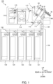
- Fig. 1 is a left side view illustrating an internal configuration of the automatic transaction apparatus 100.
- the up and down, front and back, and left-right directions illustrated in Fig. 1 and Figs. 2A to 4B to be described later are merely an example of a case where a customer side of the automatic transaction apparatus 100 is the front direction, but for example, the up-down direction is a vertical direction, and the front-back direction and the left-right direction are horizontal directions.
- the automatic transaction apparatus 100 illustrated in Fig. 1 is, for example, an ATM, a bill recycle unit (BRU), a cash dispenser (CD), a teller cash recycler (TCR), or the like, and includes a main body unit 110, an intermediate conveying unit 120, and a storage unit 130.
- the main body unit 110 and the storage unit 130 are arranged in different spaces via a partition (not illustrated) interposed therebetween, and the intermediate conveying unit 120 conveys a banknote B (see Fig. 2A ) so as to penetrate the partition.
- the banknote B is an example of a paper sheet.
- the main body unit 110 includes a banknote deposit/withdrawal unit 1, conveying units 111 and 113, a distinguishing unit 112, a temporarily holding unit 114, and a reject unit 115.
- the banknote deposit/withdrawal unit 1 includes a stage 10, a roof 20, a pusher 30, a taking-in and conveying unit 40, a discharge conveying unit 50, a front panel 60, a shutter 70, a first contact portion 80 (see Fig. 3A ), and a banknote receiving portion 90 (see Fig. 10 ). Note that only the banknote deposit/withdrawal unit 1 can be regarded as an example of the paper sheet handling apparatus.
- the stage 10, the roof 20, the pusher 30, the taking-in and conveying unit 40, the first contact portion 80, and the banknote receiving portion 90 will be described later with reference to Figs. 3A to 3C , 4A and 4B , and Figs. 5 to 10 , but the taking-in and conveying unit 40 conveys the banknote B inserted from the insertion/taking-out port 61 to the insertion space S1 (see Fig. 3A ) between the stage 10 and the pusher 30 to take the banknote B into the automatic transaction apparatus 100.
- the taking-in and conveying unit 40 conveys the banknote B for withdrawal left without being taken out in a taking-out space S2 (see Fig. 4A ) between the pusher 30 and the roof 20 to take the banknote B into the automatic transaction apparatus 100.
- the discharge conveying unit 50 illustrated in Fig. 1 discharges the banknote B between the roof 20 and the pusher 30.
- the front panel 60 On an upper front surface of the automatic transaction apparatus 100, the front panel 60 is disposed to be inclined with respect to the vertical direction and the horizontal direction so as to be located rearward as going upward.
- the front panel 60 is provided with an insertion/taking-out port 61.
- the shutter 70 openably closes the insertion/taking-out port 61, which is an example of an insertion port, through which the banknote B (paper sheet) is inserted. Note that, in Fig. 1 , the shutter 70 in an opened state is illustrated by a solid line, and the shutter 70 in a closed state is illustrated by a dotted line.
- the conveying unit 111 conveys the banknote B from the banknote deposit/withdrawal unit 1 to the distinguishing unit 112, and conveys the banknote B between the distinguishing unit 112 and the intermediate conveying unit 120.
- the distinguishing unit 112 determines authenticity, contamination, corner breakage, and the like of the banknote B.
- the conveying unit 113 conveys the banknote B between the distinguishing unit 112 and the temporarily holding unit 114, and conveys the banknote B from the distinguishing unit 112 to the banknote deposit/withdrawal unit 1.
- the temporarily holding unit 114 temporarily stores the banknote B that is inserted into the banknote deposit/withdrawal unit 1 and determined to be normal in the distinguishing unit 112.
- the reject unit 115 stores a banknote B, which is not to be returned, among such banknotes B determined to be abnormal in the distinguishing unit 112.
- the intermediate conveying unit 120 conveys the banknote B between the main body unit 110 and the storage unit 130.
- the storage unit 130 is disposed below the main body unit 110, and includes a plurality of banknote storage cassettes 131, 132, 133, 134, and 135, and a storage conveying unit 136.
- the plurality of banknote storage cassettes 131 to 135 store, for example, such banknotes B of which money types are different from one another.
- the banknote storage cassettes 131 to 135 can eject the stored banknotes B. Therefore, the banknotes B stored in the banknote storage cassettes 131 are 135 are used for withdrawal.
- the storage conveying unit 136 conveys the banknotes B between the intermediate conveying unit 120 and the respective banknote storage cassettes 131 to 135.
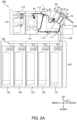
- Figs. 2A to 2C are explanatory views for explaining conveyance routes R1 to R4 of the automatic transaction apparatus 100 for the banknotes B.
- the banknote B inserted into the banknote deposit/withdrawal unit 1 is conveyed to the distinguishing unit 112 by the taking-in and conveying unit 40 and the conveying unit 111. Further, the banknote B determined to be normal in the distinguishing unit 112 is conveyed to the temporarily holding unit 114 by the conveying unit 113.
- the banknote B (counterfeit banknote and the like) determined to be abnormal in the distinguishing unit 112 is returned to the banknote deposit/withdrawal unit 1 by the conveying unit 113 and the discharge conveying unit 50.
- the banknotes B temporarily stored in the temporarily holding unit 114 are conveyed to the respective banknote storage cassettes 131 to 135 by the conveying unit 113, the distinguishing unit 112, the conveying unit 111, the intermediate conveying unit 120, and the storage conveying unit 136.
- the banknotes B stored in the respective banknote storage cassettes 131 to 135 are discharged, at the time of withdrawal, to the banknote deposit/withdrawal unit 1 by the storage conveying unit 136, the intermediate conveying unit 120, the conveying unit 111, the distinguishing unit 112, the conveying unit 113, and the discharge conveying unit 50.
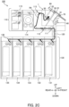
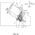
- Figs. 3A to 3C are explanatory diagrams for explaining the depositing operation of the banknote deposit/withdrawal unit 1.
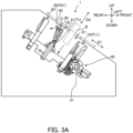
- Figs. 4A and 4B are explanatory diagrams for explaining the remaining banknote taking-in operation of the banknote deposit/withdrawal unit 1.
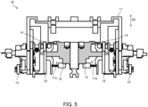
- Fig. 5 is a view of the stage 10 as viewed from the V direction in Fig. 3B .
- Fig. 6 is a view of the stage 10 as viewed from the VI direction in Fig. 3C .
- Fig. 7 is a view of the pusher 30 when viewed from the direction VII in Fig. 4A .
- Fig. 8 is a view of the pusher 30 when viewed from the direction VIII in Fig. 4B .
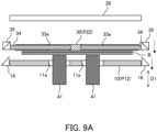
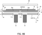
- Figs. 9A to 9C are explanatory diagrams for explaining opening and closing of second shutters 34 of the pusher 30.
- Fig. 10 is a perspective view illustrating the banknote receiving portion 90.
- the stage 10 and the roof 20 are arranged so as to be opposed to each other across the insertion space S1.
- the banknote B is inserted from the insertion/taking-out port 61 of the front panel 60 indicated by a two-dot chain line in Figs. 3A to 4B .
- the stage 10 and the roof 20 are arranged to be inclined in the vertical direction and the horizontal direction so as to be positioned upward toward the front in parallel to an insertion/taking-out direction D2 in which the banknote B is inserted and taken out. Therefore, an opposing direction D1 in which the stage 10 and the roof 20 are opposed to each other is orthogonal to the insertion/taking-out direction D2, and is inclined in the vertical direction and the horizontal direction so as to be upward toward the rear side.
- the stage 10 includes a stage main body 11, two first shutters 12 (hatched portions), two gears 13, two gears 14, and two racks 15. Note that the stage 10 is an example of a first opposing portion.
- the stage 10 is arranged so as to be movable in the opposing direction D1 in which the stage 10 and the roof 20 are opposed to each other, to an insertion position P11 (see Figs. 3A and 3B ) at the time of inserting the banknote B and a conveyance position P12 (see Fig. 3C ) at the time of conveying the inserted banknote B by pickup rollers 41 of the taking-in and conveying unit 40 to be described later.
- the stage 10 is also arranged so as to be movable to a taking-out position P13 (see Fig. 4A ) at which the banknote B is taken out and a remaining banknote conveyance position P14 ( Fig. 4B ).
- the stage main body 11 is provided with two first opening portions 11a that are penetrated by the pickup rollers 41 of the taking-in and conveying unit 40.
- the two first shutters 12 openably close the first opening portions 11a.
- the two gears 13 are respectively provided at left and right end portions of a lower end of the stage 10 (stage main body 11).
- stage 10 moves from the insertion position P11 illustrated in Fig. 3A to the conveyance position P12 illustrated in Fig. 3C , the two gears 13 mesh with two racks 42 of the taking-in and conveying unit 40 described later and rotate.
- the two gears 14 rotate along with the rotation of the two gears 13.
- the two racks 15 move up and down along with the rotation of the two gears 14.
- the two racks 15 are provided integrally with the first shutters 12, or are fixed to the first shutters 12.
- the two gears 13 mesh with the two racks 42 of the taking-in and conveying unit 40 and rotate, so that the two gears 14 rotate, the two racks 15 ascend, and the two first shutters 12 ascend.
- the two first shutters 12 open so as to open the two first opening portions 11a.
- the stage 10 moves from the conveyance position P12 illustrated in Fig. 3C or the remaining banknote conveyance position P14 illustrated in Fig. 4B to the insertion position P11 illustrated in Fig. 3A or the taking-out position P13 illustrated in Fig. 4A , the two gears 13 mesh with the two racks 42 of the taking-in and conveying unit 40 and reversely rotate, so that the two gears 14 reversely rotate, the two racks 15 descend, and the two first shutters 12 descend. As a result, as illustrated in Fig. 5 , the two first shutters 12 close the two first opening portions 11a.
- the two gears 13, the two gears 14, and the two racks 15 of the stage 10 are an example of a first shutter opening/closing unit that opens the first opening portion 11a by meshing with each other and opening the first shutter 12 when the stage 10 moves from the insertion position P11 to the conveyance position P12 and the remaining banknote conveyance position P14.
- the two racks 42 of the taking-in and conveying unit 40 are an example of a first shutter opening/closing unit included in the taking-in and conveying unit 40.
- the opening/closing direction of the two first shutters 12 is not limited to the up-down direction, and may be the left-right direction. Further, when the two first shutters 12 are opened, they may move downward instead of upward. As described above, the opening/closing direction of the first shutter 12 is arbitrary. Although the two first opening portions 11a are provided according to the number of pickup rollers 41, one or three or more first opening portions 11a may be provided. In addition, when a single first shutter 12 closes the plurality of first opening portions 11a, the number of first shutters 12 may be smaller than the number of first opening portions 11a.
- the roof 20 is movable in the opposing direction D1, and moves so as to approach the pusher 30 in order to sandwich the banknote B with the pusher 30 at the time of taking in and conveying the banknote B illustrated in Fig. 4B .
- the roof 20 is an example of a second opposing portion.
- the pusher 30 includes a movable member 31, a rotating shaft 32 (see Fig. 3A ), a pusher main body 33, two second shutters 34 (hatched portions), two fitting portions 35, two gears 36, and two racks 37.
- the pusher 30 is an example of a partition portion arranged between the stage 10 and the roof 20 so as to be movable in the opposing direction D1 between the stage 10 and the roof 20.
- the pusher 30 forms, with the stage 10, the insertion space S1 into which the banknote B is inserted from the insertion/taking-out port 61 at the insertion position P21.
- the pusher 30 forms, with the roof 20, the taking-out space S2 in which the banknote B is taken out from the insertion/taking-out port 61 at a taking-out position P23.
- the pusher 30 is also movable to a conveyance position P22 illustrated in Fig. 3C or the remaining banknote conveyance position P14 illustrated in Fig. 4B when the inserted banknote B is conveyed by the pickup rollers 41.
- the pusher 30 includes a movable member 31 that is provided at a distal end on the insertion/taking-out port 61 side and is movable toward the stage 10 side (see Fig. 4A ) and the roof 20 side (see Fig. 3A ).
- the movable member 31 is preferably provided only in a part near the center of the pusher 30 (pusher main body 33) in the left-right direction (the left-right direction in Fig. 7 ) intersecting the opposing direction D1 and the insertion/taking-out direction D2.
- the movable member 31 is supported so as to be rotatable about the rotating shaft 32. Further, the movable member 31 is preferably biased by an elastic body such as a torsion spring so as to maintain a position parallel to the stage 10 and the roof 20. A pressed projection 31a protruding downward (toward the stage 10) is provided on the movable member 31 on the side opposite to the insertion/taking-out port 61 across the rotating shaft 32.
- the pusher main body 33 is provided with two second opening portions 33a which are penetrated by two pickup rollers 41 of the taking-in and conveying unit 40 described later.
- the two second shutters 34 openably close the second opening portions 33a.
- the two gears 36 rotate in conjunction with the movement of the two fitting portions 35 away from each other in the left-right direction.
- the stage 10 and the pusher 30 are located at the conveyance positions P12 and P22 of the deposited banknote B as illustrated in Fig. 9A
- the stage 10 and the pusher 30 are located at the taking-out positions P13 and P23 when the banknote B to be withdrawn is taken out as illustrated in Fig. 9B
- the fitting between the two fitting portions 16 and the two fitting portions 35 is released, and the two fitting portions 16 are returned to the original positions by, for example, a biasing force of a biasing means (not illustrated).
- the two fitting portions 35 also return to the original positions by, for example, a biasing force of a biasing means (not illustrated).
- the opening/closing direction of the two second shutters 34 is not limited to the left-right direction, and may be the up-down direction. Moreover, when opening, the two second shutters 34 may move not in such a mutually separating direction but in a mutually approaching direction. As described above, the opening/closing direction of the second shutters 34 is arbitrary. Although the two second opening portions 33a are provided according to the number of pickup rollers 41, but one or three or more second opening portions 33a may be provided. In addition, when a single second shutter 34 closes the plurality of second opening portions 33a, the number of second shutters 34 may be smaller than the number of second opening portions 33a.
- the taking-in and conveying unit 40 illustrated in Fig. 3B includes the pickup rollers 41 and the racks 42. Although not illustrated in Fig. 3B , the two pickup rollers 41 and the two racks 42 are arranged (see Figs. 9A to 9C for the two pickup rollers 41).
- the two pickup rollers 41 convey the banknote B inserted into the insertion space S1 in a state of protruding from the two first opening portions 11a of the stage 10 toward the insertion space S1 (see Fig. 3A ).
- the two pickup rollers 41 convey the banknote B left in the taking-out space S2 in a state of protruding toward the taking-out space S2 (see Fig. 4A ) from the two first opening portions 11a (see Fig. 5 ) of the stage 10 and the two second opening portions 33a (see Fig. 7 ) of the pusher 30.
- the taking-in and conveying unit 40 is an example of a conveying unit that conveys the banknote B (paper sheet) inserted in the insertion space S1 in a state of protruding from the first opening portions 11a of the stage 10 toward the insertion space S1, and conveys the banknote B left in the taking-out space S2 in a state of protruding from the first opening portions 11a of the stage 10 and the second opening portions 33a of the pusher 30 toward the taking-out space S2.
- the banknote B paper sheet
- the taking-in and conveying unit 40 may be arranged not on the stage 10 side but on the roof 20 side.
- the first opening portions 11a and the first shutters 12 are arranged on the roof 20 instead of the stage 10.
- the stage 10 and the pusher 30 are positioned below the taking-out space S2 (the stage 10 is further positioned below the insertion space S1) unlike the roof 20, and thus foreign matter easily enters the inside of the banknote deposit/withdrawal unit 1 from the second opening portions 33a of the pusher 30 and the first opening portions 11a of the stage 10 as compared with the case where the roof 20 is provided with the first opening portions.
- the taking-in and conveying unit 40 is arranged not on the roof 20 side but on the stage 10 side due to restrictions on the device structure of the banknote deposit/withdrawal unit 1.
- the first contact portion 80 is a protrusion that is provided behind the insertion/taking-out port 61 and protrudes downward from the back surface of the front panel 60.
- the banknote receiving portion 90 includes four support members 91, a base portion 92, and four reinforcement portions 93.
- the banknote receiving portion 90 is arranged so as to be movable in the insertion/taking-out direction D2, that is, a direction approaching and separating from the taking-out port 61.
- the support members 91 are arms that support the banknote B.
- the support members 91 are arranged in the taking-out space S2 so as to face the insertion/taking-out port 61 as illustrated in Fig. 4A .
- the four support members 91 are fixed to the base portion 92.
- the base portion 92 is provided with a recessed portion 92a for avoiding interference with the pusher 30.
- Each of the four reinforcement portions 93 is provided between each support member 91 and the base portion 92 to reinforce the support member 91, and has a triangular plate shape.
- the pusher 30 forms the insertion space S1 with the stage 10 at the insertion position P21 when the banknote B is inserted.
- the movable member 31 comes into contact with the first contact portion 80 and is pressed against the elastic force of the elastic body, so that the movable member 31 moves to be inclined toward the roof 20.
- the insertion space S1 (between the pusher 30 and the stage 10) becomes wider toward the insertion/taking-out port 61, so that the customer can easily insert the banknote B.
- the movable member 31 may move so as to be inclined toward the roof 20 by, for example, power of a driving means (not illustrated).
- the pusher 30 moves toward the stage 10 after completion of the insertion of the banknote B, and sandwiches the banknote B with the stage 10.
- the stage 10 moves obliquely downward toward the front together with the pusher 30 to the conveyance position P12 on the taking-in and conveying unit 40 side.
- the two first shutters 12 of the stage 10 are opened, and the first opening portion 11a is exposed.
- the banknote B is conveyed toward the conveying unit 111 illustrated in Fig. 1 by the taking-in and conveying unit 40 in a state where the two pickup rollers 41 of the taking-in and conveying unit 40 protrude from the two first opening portions 11a provided in the stage 10.
- the pusher 30 moves toward the stage 10 together with the roof 20 as illustrated in Fig. 4A .
- the pusher 30 forms the taking-out space S2 with the roof 20 at the taking-out position P23.
- the pressed projection 31a comes into contact with the stage 10 and is pressed against the elastic force of the elastic body, so that the movable member 31 moves so as to be inclined toward the stage 10.
- the taking-out space S2 (between the pusher 30 and the roof 20) becomes wider toward the insertion/taking-out port 61, the customer can easily take out the banknote B.
- the stage 10 functions as an example of a second contact portion that moves the movable member 31 toward the stage 10 by coming into contact with the movable member 31.
- the movable member 31 may be moved so as to be inclined toward the stage 10 by, for example, power of a driving means (not illustrated).
- the movable member 31 may move so as to be inclined toward the stage 10 by coming into contact with the second contact portion other than the stage 10.
- the movable member 31 may be in contact with the stage 10 (second contact portion) at a portion other than the pressed projection 31a.
- the support member 90 supporting the banknote B moves toward the insertion/taking-out port 61. Then, the customer takes out the banknote B.
- the stage 10 moves obliquely downward toward the front to the remaining banknote conveyance position P14, and the pusher 30 moves obliquely downward toward the front to the remaining banknote conveyance position P24.
- the two first shutters 12 of the stage 10 are opened, and the two first opening portions 11a are exposed.
- the two second shutters 34 of the pusher 30 are opened, and the two second opening portions 33a are exposed.
- the roof 20 also moves obliquely downward toward the front so as to sandwich the banknote B left between the roof 20 and the pusher 30.
- the left banknote B is conveyed toward the conveying unit 111 illustrated in Fig. 1 by the taking-in and conveying unit 40.
- the automatic transaction apparatus 100 which is an example of a paper sheet handling apparatus, includes the stage 10 (an example of a first opposing portion), the roof 20 (an example of a second opposing portion), the pusher 30 (an example of a partition portion), and the taking-in and conveying unit 40 (an example of a conveying unit).
- the stage 10 and the roof 20 are arranged so as to be opposed to each other.
- the pusher 30 is arranged so as to be movable in the opposing direction D1 in which the stage 10 and the roof 20 are opposed to each other, forms the insertion space S1 in which the banknote B (an example of a paper sheet) is inserted from the insertion/taking-out port 61 (an example of an insertion port) with the stage 10, and forms the taking-out space S2 in which the banknote B is taken out from the insertion/taking-out port 61 with the roof 20.
- the taking-in and conveying unit 40 conveys the banknote B inserted in the insertion space S1 in a state of protruding from the first opening portions 11a of the stage 10 toward the insertion space S1, and conveys the banknote B left in the taking-out space S2 in a state of protruding from the first opening portions 11a of the stage 10 and the second opening portions 33a of the pusher 30 toward the taking-out space S2.
- the pusher 30 is arranged so as to be movable to the remaining banknote conveyance position P24 when the banknote B left in the taking-out space S2 is conveyed by the taking-in and conveying unit 40.
- the pusher 30 includes the second shutters 34 that openably close the second opening portions 33a, and the second shutter opening/closing unit (for example, the two fitting portions 35, the two gears 36, and the two racks 37) that opens the second opening portions 33a by opening the second shutters 34 in conjunction with the operation in which the pusher 30 moves to the remaining banknote conveyance position P24.
- the second shutter opening/closing unit for example, the two fitting portions 35, the two gears 36, and the two racks 37
- the second shutters 34 that close the second opening portions 33a are arranged, so that it is possible to prevent foreign matter from moving from the second opening portions 33a to the stage 10 side (insertion space S1 side) and the roof 20 side (taking-out space S2 side).
- fitting portions 35 or the like which are an example of a second shutter opening/closing unit, open the second shutters 34 in conjunction with the operation in which the pusher 30 moves to the remaining banknote conveyance position P24, so that it is possible to omit arrangement of a driving unit such as a motor, a power transmission mechanism that transmits power from the driving unit to the second shutters 34, and the like.
- the second shutters 34 that close the second opening portions 33a of the pusher 30 can be opened with a simple configuration.
- the stage 10 is arranged so as to be movable to the remaining banknote conveyance position P14 when the banknote B left in the taking-out space S2 is conveyed by the taking-in and conveying unit 40, and the second shutter opening/closing unit is fitted to the stage 10 (fitting portions 16) and pressed by the stage 10 (fitting portions 16) to open the second shutters 34 when the stage 10 and the pusher 30 are at the remaining banknote conveyance positions P14 and P24.
- the second shutters 34 can be opened with a simple configuration as compared with the case where the fitting portions 35 are pressed by a member other than the stage 10 such as the periphery of the stage 10.
- the fitting portions 16 press the fitting portions 35 in a state of being fitted to the fitting portions 35, the second shutters 34 can be reliably opened.
- the stage 10 includes the first shutters 12 that openably close the first opening portions 11a
- the stage 10 is arranged so as to be movable in the opposing direction D1 at the insertion position P11 at the time of inserting the banknote B, the conveyance position P12 at the time of conveying the banknote B by the taking-in and conveying unit 40, and the remaining banknote conveyance position P14
- each of the stage 10 and the taking and conveying unit 40 includes the first shutter opening/closing unit (for example, the two gears 13, the two gears 14, and the two racks 15, and the two racks 42) that opens the first opening portions 11a by opening the first shutters 12 by meshing with each other when the stage 10 moves from the insertion position P11 to the conveyance position P12 and the remaining banknote conveyance position P14.
Landscapes
- Engineering & Computer Science (AREA)
- Mechanical Engineering (AREA)
- Physics & Mathematics (AREA)
- General Physics & Mathematics (AREA)
- Sheets, Magazines, And Separation Thereof (AREA)
- Pile Receivers (AREA)
Claims (3)
- Papierblatthandhabungsvorrichtung (100), umfassend:einen ersten gegenüberliegenden Abschnitt (10) und einen zweiten gegenüberliegenden Abschnitt (20), die einander gegenüberliegend angeordnet sind;einen Trennabschnitt (30), der so angeordnet ist, dass er in eine entgegengesetzte Richtung (D1), in der der erste gegenüberliegende Abschnitt (10) und der zweite gegenüberliegende Abschnitt (20) einander gegenüberliegen, bewegbar ist, einen Einführungsraum (S1) bildet, in den ein Papierblatt (B) von einem Einführungsschlitz (61) mit dem ersten gegenüberliegenden Abschnitt (10) eingeführt wird, und einen Entnahmeraum (S2) bildet, aus dem das Papierblatt (B) mit dem zweiten gegenüberliegenden Abschnitt (20) aus dem Einführungsschlitz (61) entnommen wird; undeine Fördereinheit (40), die so konfiguriert ist, das sie das in den Einführungsraum (S1) eingelegte Papierblatt (B) in einem Zustand des Vorstehens zu dem Einführungsraum (S1) hin von einem ersten Öffnungsabschnitt (11a) des ersten gegenüberliegenden Abschnitts (10) fördert, und so konfiguriert ist, dass sie das Papierblatt (B), das in dem Entnahmeraum (S2) belassen wird, in einem Zustand des Vorstehens zu dem Entnahmeraum (S2) hin von dem ersten Öffnungsabschnitt (11a) des ersten gegenüberliegenden Abschnitts (10) und einem zweiten Öffnungsabschnitt (33a) des Trennabschnitts (30) fördert,wobei der Trennabschnitt (30) so angeordnet ist, dass er in eine verbleibende Banknotenförderposition (P24) bewegbar ist, wenn das Papierblatt (B), das in dem Entnahmeraum (S2) belassen wird, von der Fördereinheit (40) gefördert wird, undwobei der Trennabschnitt (30) einen zweiten Verschluss (34) beinhaltet, der so konfiguriert ist, dass er den zweiten Öffnungsabschnitt (33a) öffnungsfähig schließt, und eine zweite Verschlussöffnungs-/Schließeinheit (35, 36, 37), die so konfiguriert ist, dass sie den zweiten Öffnungsabschnitt (33a) öffnet, indem sie den zweiten Verschluss (34) in Verbindung mit einem Vorgang öffnet, in dem sich der Trennabschnitt (30) zu der verbleibenden Banknotenförderposition (P24) bewegt.
- Papierblatthandhabungsvorrichtung (100) nach Anspruch 1, wobei der erste gegenüberliegende Abschnitt (10) so angeordnet ist, dass er in die verbleibende Banknotenförderposition (P24) bewegbar ist, wenn das Papierblatt (B), das in dem Entnahmeraum (S2) belassen wird, durch die Fördereinheit (40) gefördert wird, und
wobei die zweite Verschlussöffnungs-/Schließeinheit (35, 36, 37) so konfiguriert ist, dass sie den zweiten Verschluss (34) öffnet, indem sie an dem ersten gegenüberliegenden Abschnitt (10) angebracht und von dem ersten gegenüberliegenden Abschnitt (10) gedrückt wird, wenn der erste gegenüberliegende Abschnitt (10) und der Trennabschnitt (30) an der verbleibenden Banknotenförderposition (P24) sind. - Papierblatthandhabungsvorrichtung (100) nach Anspruch 2, wobei der erste gegenüberliegende Abschnitt (10) einen ersten Verschluss (12) beinhaltet, der so konfiguriert ist, dass er den ersten Öffnungsabschnitt (11a) öffnungsfähig schließt,wobei der erste gegenüberliegende Abschnitt (10) so angeordnet ist, dass er in die entgegengesetzte Richtung (D1) zu einer Einführungsposition (P11) zum Zeitpunkt des Einführens des Papierblatts (B), einer Förderposition (P12) zum Zeitpunkt des Förderns des Papierblatts (B) durch die Fördereinheit (40) und der verbleibenden Banknotenförderposition (P24) bewegbar ist, undwobei jeder des ersten gegenüberliegenden Abschnitts (10) und die Fördereinheit (40) eine erste Verschlussöffnungs-/Schließeinheit (13, 14, 15, 42) beinhalten, die so konfiguriert ist, dass sie den ersten Öffnungsabschnitt (11a) durch Öffnen des ersten Verschlusses (12) durch Ineinandergreifen öffnet, wenn sich der erste gegenüberliegende Abschnitt (10) von der Einführungsposition (P11) zu der Förderposition (P12) und der verbleibenden Banknotenförderposition (P24) bewegt.
Applications Claiming Priority (1)
| Application Number | Priority Date | Filing Date | Title |
|---|---|---|---|
| PCT/JP2021/006536 WO2022176178A1 (ja) | 2021-02-22 | 2021-02-22 | 紙葉類取扱装置 |
Publications (3)
| Publication Number | Publication Date |
|---|---|
| EP4296983A1 EP4296983A1 (de) | 2023-12-27 |
| EP4296983A4 EP4296983A4 (de) | 2024-04-24 |
| EP4296983B1 true EP4296983B1 (de) | 2025-03-26 |
Family
ID=82930423
Family Applications (1)
| Application Number | Title | Priority Date | Filing Date |
|---|---|---|---|
| EP21926609.5A Active EP4296983B1 (de) | 2021-02-22 | 2021-02-22 | Papierblatthandhabungsvorrichtung |
Country Status (5)
| Country | Link |
|---|---|
| US (1) | US12444262B2 (de) |
| EP (1) | EP4296983B1 (de) |
| JP (1) | JP7392198B2 (de) |
| CN (1) | CN116783634A (de) |
| WO (1) | WO2022176178A1 (de) |
Families Citing this family (1)
| Publication number | Priority date | Publication date | Assignee | Title |
|---|---|---|---|---|
| WO2024176282A1 (ja) * | 2023-02-20 | 2024-08-29 | 富士通フロンテック株式会社 | 紙葉類取扱装置 |
Family Cites Families (17)
| Publication number | Priority date | Publication date | Assignee | Title |
|---|---|---|---|---|
| JP4446806B2 (ja) * | 2004-06-16 | 2010-04-07 | 日立オムロンターミナルソリューションズ株式会社 | 紙幣処理装置 |
| JP2006309681A (ja) * | 2005-04-30 | 2006-11-09 | M Ii Shii:Kk | 紙幣識別収納装置 |
| JP2006350415A (ja) * | 2005-06-13 | 2006-12-28 | Hitachi Omron Terminal Solutions Corp | 現金取扱装置 |
| JP5292761B2 (ja) * | 2007-10-16 | 2013-09-18 | 沖電気工業株式会社 | 紙幣分離集積機構 |
| JP5332512B2 (ja) * | 2008-10-29 | 2013-11-06 | 沖電気工業株式会社 | 紙幣入出金機構 |
| KR101094499B1 (ko) * | 2010-08-03 | 2011-12-20 | 엘지엔시스(주) | 금융자동화기기 |
| JP5342530B2 (ja) * | 2010-09-29 | 2013-11-13 | 日立オムロンターミナルソリューションズ株式会社 | 現金自動取引装置 |
| JP6165652B2 (ja) | 2014-02-20 | 2017-07-19 | 富士通フロンテック株式会社 | 紙葉類入出装置 |
| JP6466072B2 (ja) * | 2014-03-06 | 2019-02-06 | グローリー株式会社 | 紙葉類投入装置および紙葉類処理機 |
| KR20150125227A (ko) * | 2014-04-30 | 2015-11-09 | 주식회사 푸른기술 | 에스크로형 지폐 입금기의 시건 장치 |
| JP6308675B2 (ja) * | 2014-11-14 | 2018-04-11 | ローレル精機株式会社 | 紙幣処理機 |
| CN104851185B (zh) * | 2015-05-28 | 2017-06-23 | 广州广电运通金融电子股份有限公司 | 一种新型闸门装置 |
| JP6813383B2 (ja) * | 2016-11-04 | 2021-01-13 | グローリー株式会社 | 紙葉類処理装置 |
| DE102019125993A1 (de) * | 2019-09-26 | 2021-04-01 | Wincor Nixdorf International Gmbh | Vorrichtung zur Handhabung von Wertscheinen |
| EP4109425B1 (de) * | 2020-02-21 | 2026-03-25 | Fujitsu Frontech Limited | Papierblatthandhabungsvorrichtung |
| WO2021166258A1 (ja) * | 2020-02-21 | 2021-08-26 | 富士通フロンテック株式会社 | 紙葉類取扱装置 |
| JP7196360B2 (ja) * | 2020-02-21 | 2022-12-26 | 富士通フロンテック株式会社 | 紙葉類取扱装置 |
-
2021
- 2021-02-22 WO PCT/JP2021/006536 patent/WO2022176178A1/ja not_active Ceased
- 2021-02-22 JP JP2023500475A patent/JP7392198B2/ja active Active
- 2021-02-22 EP EP21926609.5A patent/EP4296983B1/de active Active
- 2021-02-22 CN CN202180092050.5A patent/CN116783634A/zh active Pending
-
2023
- 2023-07-24 US US18/357,508 patent/US12444262B2/en active Active
Also Published As
| Publication number | Publication date |
|---|---|
| WO2022176178A1 (ja) | 2022-08-25 |
| EP4296983A4 (de) | 2024-04-24 |
| US12444262B2 (en) | 2025-10-14 |
| JP7392198B2 (ja) | 2023-12-05 |
| EP4296983A1 (de) | 2023-12-27 |
| US20230368598A1 (en) | 2023-11-16 |
| CN116783634A (zh) | 2023-09-19 |
| JPWO2022176178A1 (de) | 2022-08-25 |
Similar Documents
| Publication | Publication Date | Title |
|---|---|---|
| KR101224937B1 (ko) | 지폐 수납고 및 지폐 취급 장치 | |
| KR101502987B1 (ko) | 지폐 수납고 및 지폐 취급 장치 | |
| KR101089655B1 (ko) | 지엽류 취급 장치 | |
| JP5500190B2 (ja) | 媒体取引装置 | |
| US12536858B2 (en) | Paper sheet handling apparatus | |
| JP5553134B2 (ja) | 媒体取引装置 | |
| US12444262B2 (en) | Paper sheet handling apparatus | |
| KR101116932B1 (ko) | 지엽류 취급 장치 | |
| US12462632B2 (en) | Paper sheet handling apparatus | |
| EP3745366B1 (de) | Papierblattverarbeitungsvorrichtung | |
| JP2010198253A (ja) | 紙葉類取扱装置 | |
| JP7426178B2 (ja) | 紙葉類取扱装置 | |
| KR20170017064A (ko) | 매체 처리 장치 및 금융 기기 | |
| JP2016184347A (ja) | 紙葉類搬送機構および紙葉類処理装置 | |
| JP7840627B2 (ja) | 紙葉類取扱装置 |
Legal Events
| Date | Code | Title | Description |
|---|---|---|---|
| STAA | Information on the status of an ep patent application or granted ep patent |
Free format text: STATUS: THE INTERNATIONAL PUBLICATION HAS BEEN MADE |
|
| PUAI | Public reference made under article 153(3) epc to a published international application that has entered the european phase |
Free format text: ORIGINAL CODE: 0009012 |
|
| STAA | Information on the status of an ep patent application or granted ep patent |
Free format text: STATUS: REQUEST FOR EXAMINATION WAS MADE |
|
| 17P | Request for examination filed |
Effective date: 20230726 |
|
| AK | Designated contracting states |
Kind code of ref document: A1 Designated state(s): AL AT BE BG CH CY CZ DE DK EE ES FI FR GB GR HR HU IE IS IT LI LT LU LV MC MK MT NL NO PL PT RO RS SE SI SK SM TR |
|
| A4 | Supplementary search report drawn up and despatched |
Effective date: 20240325 |
|
| RIC1 | Information provided on ipc code assigned before grant |
Ipc: B65H 1/02 20060101ALI20240319BHEP Ipc: B65H 3/06 20060101ALI20240319BHEP Ipc: B65H 31/30 20060101ALI20240319BHEP Ipc: G07D 11/14 20190101AFI20240319BHEP |
|
| DAV | Request for validation of the european patent (deleted) | ||
| DAX | Request for extension of the european patent (deleted) | ||
| GRAP | Despatch of communication of intention to grant a patent |
Free format text: ORIGINAL CODE: EPIDOSNIGR1 |
|
| STAA | Information on the status of an ep patent application or granted ep patent |
Free format text: STATUS: GRANT OF PATENT IS INTENDED |
|
| INTG | Intention to grant announced |
Effective date: 20241029 |
|
| GRAS | Grant fee paid |
Free format text: ORIGINAL CODE: EPIDOSNIGR3 |
|
| GRAA | (expected) grant |
Free format text: ORIGINAL CODE: 0009210 |
|
| STAA | Information on the status of an ep patent application or granted ep patent |
Free format text: STATUS: THE PATENT HAS BEEN GRANTED |
|
| AK | Designated contracting states |
Kind code of ref document: B1 Designated state(s): AL AT BE BG CH CY CZ DE DK EE ES FI FR GB GR HR HU IE IS IT LI LT LU LV MC MK MT NL NO PL PT RO RS SE SI SK SM TR |
|
| REG | Reference to a national code |
Ref country code: GB Ref legal event code: FG4D |
|
| REG | Reference to a national code |
Ref country code: CH Ref legal event code: EP |
|
| REG | Reference to a national code |
Ref country code: DE Ref legal event code: R096 Ref document number: 602021028325 Country of ref document: DE |
|
| REG | Reference to a national code |
Ref country code: IE Ref legal event code: FG4D |
|
| PG25 | Lapsed in a contracting state [announced via postgrant information from national office to epo] |
Ref country code: RS Free format text: LAPSE BECAUSE OF FAILURE TO SUBMIT A TRANSLATION OF THE DESCRIPTION OR TO PAY THE FEE WITHIN THE PRESCRIBED TIME-LIMIT Effective date: 20250626 |
|
| PG25 | Lapsed in a contracting state [announced via postgrant information from national office to epo] |
Ref country code: FI Free format text: LAPSE BECAUSE OF FAILURE TO SUBMIT A TRANSLATION OF THE DESCRIPTION OR TO PAY THE FEE WITHIN THE PRESCRIBED TIME-LIMIT Effective date: 20250326 |
|
| REG | Reference to a national code |
Ref country code: LT Ref legal event code: MG9D |
|
| PG25 | Lapsed in a contracting state [announced via postgrant information from national office to epo] |
Ref country code: NO Free format text: LAPSE BECAUSE OF FAILURE TO SUBMIT A TRANSLATION OF THE DESCRIPTION OR TO PAY THE FEE WITHIN THE PRESCRIBED TIME-LIMIT Effective date: 20250626 |
|
| PG25 | Lapsed in a contracting state [announced via postgrant information from national office to epo] |
Ref country code: HR Free format text: LAPSE BECAUSE OF FAILURE TO SUBMIT A TRANSLATION OF THE DESCRIPTION OR TO PAY THE FEE WITHIN THE PRESCRIBED TIME-LIMIT Effective date: 20250326 |
|
| PG25 | Lapsed in a contracting state [announced via postgrant information from national office to epo] |
Ref country code: LV Free format text: LAPSE BECAUSE OF FAILURE TO SUBMIT A TRANSLATION OF THE DESCRIPTION OR TO PAY THE FEE WITHIN THE PRESCRIBED TIME-LIMIT Effective date: 20250326 |
|
| PG25 | Lapsed in a contracting state [announced via postgrant information from national office to epo] |
Ref country code: GR Free format text: LAPSE BECAUSE OF FAILURE TO SUBMIT A TRANSLATION OF THE DESCRIPTION OR TO PAY THE FEE WITHIN THE PRESCRIBED TIME-LIMIT Effective date: 20250627 Ref country code: BG Free format text: LAPSE BECAUSE OF FAILURE TO SUBMIT A TRANSLATION OF THE DESCRIPTION OR TO PAY THE FEE WITHIN THE PRESCRIBED TIME-LIMIT Effective date: 20250326 |
|
| REG | Reference to a national code |
Ref country code: NL Ref legal event code: MP Effective date: 20250326 |
|
| PG25 | Lapsed in a contracting state [announced via postgrant information from national office to epo] |
Ref country code: NL Free format text: LAPSE BECAUSE OF FAILURE TO SUBMIT A TRANSLATION OF THE DESCRIPTION OR TO PAY THE FEE WITHIN THE PRESCRIBED TIME-LIMIT Effective date: 20250326 |
|
| PG25 | Lapsed in a contracting state [announced via postgrant information from national office to epo] |
Ref country code: SE Free format text: LAPSE BECAUSE OF FAILURE TO SUBMIT A TRANSLATION OF THE DESCRIPTION OR TO PAY THE FEE WITHIN THE PRESCRIBED TIME-LIMIT Effective date: 20250326 |
|
| REG | Reference to a national code |
Ref country code: AT Ref legal event code: MK05 Ref document number: 1779743 Country of ref document: AT Kind code of ref document: T Effective date: 20250326 |
|
| PG25 | Lapsed in a contracting state [announced via postgrant information from national office to epo] |
Ref country code: SM Free format text: LAPSE BECAUSE OF FAILURE TO SUBMIT A TRANSLATION OF THE DESCRIPTION OR TO PAY THE FEE WITHIN THE PRESCRIBED TIME-LIMIT Effective date: 20250326 |
|
| PG25 | Lapsed in a contracting state [announced via postgrant information from national office to epo] |
Ref country code: ES Free format text: LAPSE BECAUSE OF FAILURE TO SUBMIT A TRANSLATION OF THE DESCRIPTION OR TO PAY THE FEE WITHIN THE PRESCRIBED TIME-LIMIT Effective date: 20250326 Ref country code: PT Free format text: LAPSE BECAUSE OF FAILURE TO SUBMIT A TRANSLATION OF THE DESCRIPTION OR TO PAY THE FEE WITHIN THE PRESCRIBED TIME-LIMIT Effective date: 20250728 |
|
| PG25 | Lapsed in a contracting state [announced via postgrant information from national office to epo] |
Ref country code: IT Free format text: LAPSE BECAUSE OF FAILURE TO SUBMIT A TRANSLATION OF THE DESCRIPTION OR TO PAY THE FEE WITHIN THE PRESCRIBED TIME-LIMIT Effective date: 20250326 Ref country code: PL Free format text: LAPSE BECAUSE OF FAILURE TO SUBMIT A TRANSLATION OF THE DESCRIPTION OR TO PAY THE FEE WITHIN THE PRESCRIBED TIME-LIMIT Effective date: 20250326 |
|
| REG | Reference to a national code |
Ref country code: GB Ref legal event code: 732E Free format text: REGISTERED BETWEEN 20250918 AND 20250924 |
|
| PG25 | Lapsed in a contracting state [announced via postgrant information from national office to epo] |
Ref country code: AT Free format text: LAPSE BECAUSE OF FAILURE TO SUBMIT A TRANSLATION OF THE DESCRIPTION OR TO PAY THE FEE WITHIN THE PRESCRIBED TIME-LIMIT Effective date: 20250326 |
|
| PG25 | Lapsed in a contracting state [announced via postgrant information from national office to epo] |
Ref country code: EE Free format text: LAPSE BECAUSE OF FAILURE TO SUBMIT A TRANSLATION OF THE DESCRIPTION OR TO PAY THE FEE WITHIN THE PRESCRIBED TIME-LIMIT Effective date: 20250326 |
|
| PG25 | Lapsed in a contracting state [announced via postgrant information from national office to epo] |
Ref country code: RO Free format text: LAPSE BECAUSE OF FAILURE TO SUBMIT A TRANSLATION OF THE DESCRIPTION OR TO PAY THE FEE WITHIN THE PRESCRIBED TIME-LIMIT Effective date: 20250326 |
|
| PG25 | Lapsed in a contracting state [announced via postgrant information from national office to epo] |
Ref country code: SK Free format text: LAPSE BECAUSE OF FAILURE TO SUBMIT A TRANSLATION OF THE DESCRIPTION OR TO PAY THE FEE WITHIN THE PRESCRIBED TIME-LIMIT Effective date: 20250326 |
|
| PG25 | Lapsed in a contracting state [announced via postgrant information from national office to epo] |
Ref country code: IS Free format text: LAPSE BECAUSE OF FAILURE TO SUBMIT A TRANSLATION OF THE DESCRIPTION OR TO PAY THE FEE WITHIN THE PRESCRIBED TIME-LIMIT Effective date: 20250726 |
|
| REG | Reference to a national code |
Ref country code: DE Ref legal event code: R097 Ref document number: 602021028325 Country of ref document: DE |
|
| PG25 | Lapsed in a contracting state [announced via postgrant information from national office to epo] |
Ref country code: DK Free format text: LAPSE BECAUSE OF FAILURE TO SUBMIT A TRANSLATION OF THE DESCRIPTION OR TO PAY THE FEE WITHIN THE PRESCRIBED TIME-LIMIT Effective date: 20250326 |
|
| PG25 | Lapsed in a contracting state [announced via postgrant information from national office to epo] |
Ref country code: CZ Free format text: LAPSE BECAUSE OF FAILURE TO SUBMIT A TRANSLATION OF THE DESCRIPTION OR TO PAY THE FEE WITHIN THE PRESCRIBED TIME-LIMIT Effective date: 20250326 |
|
| PLBE | No opposition filed within time limit |
Free format text: ORIGINAL CODE: 0009261 |
|
| STAA | Information on the status of an ep patent application or granted ep patent |
Free format text: STATUS: NO OPPOSITION FILED WITHIN TIME LIMIT |
|
| REG | Reference to a national code |
Ref country code: CH Ref legal event code: L10 Free format text: ST27 STATUS EVENT CODE: U-0-0-L10-L00 (AS PROVIDED BY THE NATIONAL OFFICE) Effective date: 20260211 |
|
| 26N | No opposition filed |
Effective date: 20260105 |
|
| PGFP | Annual fee paid to national office [announced via postgrant information from national office to epo] |
Ref country code: GB Payment date: 20260106 Year of fee payment: 6 |