EP4295671A1 - Vorrichtung zur aufzucht von pflanzen - Google Patents
Vorrichtung zur aufzucht von pflanzen Download PDFInfo
- Publication number
- EP4295671A1 EP4295671A1 EP22180324.0A EP22180324A EP4295671A1 EP 4295671 A1 EP4295671 A1 EP 4295671A1 EP 22180324 A EP22180324 A EP 22180324A EP 4295671 A1 EP4295671 A1 EP 4295671A1
- Authority
- EP
- European Patent Office
- Prior art keywords
- planting mat
- mat carrier
- carrier
- planting
- shell
- Prior art date
- Legal status (The legal status is an assumption and is not a legal conclusion. Google has not performed a legal analysis and makes no representation as to the accuracy of the status listed.)
- Pending
Links
- 239000007788 liquid Substances 0.000 claims description 38
- 230000005484 gravity Effects 0.000 claims description 8
- 230000008719 thickening Effects 0.000 claims description 6
- 230000015572 biosynthetic process Effects 0.000 claims 1
- 241000196324 Embryophyta Species 0.000 description 49
- 239000000463 material Substances 0.000 description 5
- 235000015097 nutrients Nutrition 0.000 description 3
- XLYOFNOQVPJJNP-UHFFFAOYSA-N water Substances O XLYOFNOQVPJJNP-UHFFFAOYSA-N 0.000 description 3
- 239000000969 carrier Substances 0.000 description 2
- 239000002184 metal Substances 0.000 description 2
- 238000006424 Flood reaction Methods 0.000 description 1
- QVGXLLKOCUKJST-UHFFFAOYSA-N atomic oxygen Chemical compound [O] QVGXLLKOCUKJST-UHFFFAOYSA-N 0.000 description 1
- 230000001419 dependent effect Effects 0.000 description 1
- 230000001771 impaired effect Effects 0.000 description 1
- 238000004519 manufacturing process Methods 0.000 description 1
- 229910052760 oxygen Inorganic materials 0.000 description 1
- 239000001301 oxygen Substances 0.000 description 1
- 238000007493 shaping process Methods 0.000 description 1
Images
Classifications
-
- A—HUMAN NECESSITIES
- A01—AGRICULTURE; FORESTRY; ANIMAL HUSBANDRY; HUNTING; TRAPPING; FISHING
- A01G—HORTICULTURE; CULTIVATION OF VEGETABLES, FLOWERS, RICE, FRUIT, VINES, HOPS OR SEAWEED; FORESTRY; WATERING
- A01G31/00—Soilless cultivation, e.g. hydroponics
- A01G31/02—Special apparatus therefor
-
- A—HUMAN NECESSITIES
- A01—AGRICULTURE; FORESTRY; ANIMAL HUSBANDRY; HUNTING; TRAPPING; FISHING
- A01G—HORTICULTURE; CULTIVATION OF VEGETABLES, FLOWERS, RICE, FRUIT, VINES, HOPS OR SEAWEED; FORESTRY; WATERING
- A01G31/00—Soilless cultivation, e.g. hydroponics
- A01G31/02—Special apparatus therefor
- A01G31/06—Hydroponic culture on racks or in stacked containers
-
- A—HUMAN NECESSITIES
- A01—AGRICULTURE; FORESTRY; ANIMAL HUSBANDRY; HUNTING; TRAPPING; FISHING
- A01G—HORTICULTURE; CULTIVATION OF VEGETABLES, FLOWERS, RICE, FRUIT, VINES, HOPS OR SEAWEED; FORESTRY; WATERING
- A01G9/00—Cultivation in receptacles, forcing-frames or greenhouses; Edging for beds, lawn or the like
- A01G9/14—Greenhouses
- A01G9/1423—Greenhouse bench structures
-
- Y—GENERAL TAGGING OF NEW TECHNOLOGICAL DEVELOPMENTS; GENERAL TAGGING OF CROSS-SECTIONAL TECHNOLOGIES SPANNING OVER SEVERAL SECTIONS OF THE IPC; TECHNICAL SUBJECTS COVERED BY FORMER USPC CROSS-REFERENCE ART COLLECTIONS [XRACs] AND DIGESTS
- Y02—TECHNOLOGIES OR APPLICATIONS FOR MITIGATION OR ADAPTATION AGAINST CLIMATE CHANGE
- Y02P—CLIMATE CHANGE MITIGATION TECHNOLOGIES IN THE PRODUCTION OR PROCESSING OF GOODS
- Y02P60/00—Technologies relating to agriculture, livestock or agroalimentary industries
- Y02P60/20—Reduction of greenhouse gas [GHG] emissions in agriculture, e.g. CO2
- Y02P60/21—Dinitrogen oxide [N2O], e.g. using aquaponics, hydroponics or efficiency measures
Definitions
- the present invention relates to a device for growing plants with a planting mat carrier, which has a planting mat support surface, and with a tray in which the planting mat carrier is arranged.
- the greenhouse can also be designed as a block storage arrangement, in which the trays are stacked on top of each other at a certain distance.
- the bowls possibly except for the lowest bowl, then have corresponding lighting devices on their underside in order to be able to illuminate the plants in the bowl underneath.
- planting mats In order to be able to grow the plants with as little effort as possible, seeds or seedlings are often placed on planting mats where they are allowed to pre-germinate to a certain stage. The developing plants then already have roots that penetrate the plant mats. The planting mats are or will then be placed in a bowl in which they are supplied with liquid and nutrients.
- a certain problem is how to supply the plants in the planting mats so that the plants do not receive too much, but also not too little, liquid. This is particularly difficult if the bowls are not aligned exactly horizontally. In this case, the liquid is "lopsided" in the bowl, so that some plants receive too much water and other plants receive too little water. In any case, very precise control of the liquid supply is required here. This makes growing plants in a greenhouse difficult.
- the invention is based on the object of making the cultivation of plants in a greenhouse, in particular in a block storage greenhouse, less susceptible to failure using simple means.
- planting mat carrier is buoyant.
- the planting mat carrier can then be inserted into the bowl, with a planting mat being placed on the support surface before or after the planting mat carrier is inserted into the bowl. If liquid is poured into the bowl, the plant mat carrier will float. This has the advantage that the plants on the planting mat support cannot be flooded. The planting mat carrier always ensures correct positioning of the plants on the planting mat carrier in relation to the surface of the liquid. Furthermore, this design has the advantage that even with bowls that are not exactly horizontally aligned, all plants are supplied equally with the liquid. So there are no areas that are drier or wetter. Rather, the planting mat carrier automatically aligns itself with respect to the liquid surface so that all plants are supplied evenly.
- the shell preferably has at least one liquid inlet and at least one liquid outlet. You can then automate the watering of the plants in the tray.
- the planting mat carrier has at least one floating body on its side arranged at the bottom in the direction of gravity.
- the floating body then ensures that the plant mat carrier can float.
- the floating body gives you more freedom in choosing the material for the planting mat support. You can also use materials that have a greater specific gravity than the liquid, especially water. The In this case, buoyancy is achieved or at least supported by the floating body.
- the planting mat carrier preferably has several floating bodies which are arranged symmetrically distributed over its surface. In this case, you are no longer dependent on placing the planting mat symmetrically on the planting mat support. Rather, the multiple floating bodies ensure that the plant mat carrier is stable on the liquid that is in the bowl.
- the floating body is preferably designed in one piece with the planting mat carrier. There is therefore no risk that the floating body can detach from the planting mat and the buoyancy will be impaired.
- the at least one floating body is formed by a shape of the planting mat carrier. This is a relatively simple way to make the floating body integral with the rest of the planting mat support.
- the planting mat carrier is designed as a deep-drawn part.
- the deep-drawn part can then be formed from a flat material, for example a metal sheet or a plastic plate, by placing it in a press and forming it. This makes it easy to achieve the desired geometries, in particular the shape or shapes that later form the floating body or bodies.
- the planting mat carrier has at least one through opening outside of the at least one floating body.
- the roots of the plants can then extend downwards through the passage opening extend and reach the liquid in the bowl. It is no longer necessary for the roots to penetrate the material of the planting mat carrier, so that one has greater freedom when choosing the material for the planting mat carrier.
- a through opening is arranged in an area at each corner of which a floating body is arranged.
- the area in which the through opening is arranged is therefore stabilized relative to the surface of the liquid in the shell.
- the planting mat carrier has at least one positioning stop as a boundary of the planting mat support surface.
- the planting mat can then not slip on the planting mat carrier.
- an operator receives assistance in positioning the planting mat on the support surface.
- the shell has a planting mat carrier receiving space with a length that corresponds to n times the length of the planting mat carrier, where n is an integer, and / or the shell has a planting mat carrier receiving space with a width that corresponds to an m times the width of the planting mat carrier, where m is an integer.
- the position of the plant mat carrier in the tray is also fixed.
- the width of the planting mat support runs parallel to the width of the bowl and the length of the planting mat support runs parallel to the length of the bowl. If a planting mat carrier is inserted into the shell and the length and width of the planting mat carrier receiving space corresponds to the dimensions of the planting mat carrier, then the planting mat carrier is reliably held.
- the length and/or width corresponds to an integer multiple of the length and/or width of the planting mat carrier, then you can simply insert a correspondingly larger number of planting mat carriers into the bowl, The plant mat supports then position each other and here too a change in the position of the plant mat supports in the bowl is practically impossible.
- the advantage of the buoyancy of the plant mat supports is evident.
- the plant mat supports which have the same structure and are therefore equally buoyant, cannot slide over each other when liquid is poured into the bowl.
- the plant mat carrier receiving space has a stop at at least one end, which tapers upwards in the direction of gravity.
- the plant mat supports slide downwards in the direction of gravity and are then guided exactly into their position with little effort by the stop that thickens downwards.
- At least one stop is formed by a thickening of an inside of a wall of the shell.
- the stop can then be formed in one piece with the wall, which facilitates the production of the shell.
- the wall has an outside and the thickening continues on the outside. The stop then simultaneously stabilizes the wall of the shell.
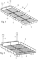
- the Fig. 1 and 2 show a device 1 for growing plants 2 with a bowl 3.
- a bowl 3 In the bowl 3 there are plant mat supports 4 ( Fig. 3 ) arranged.
- a planting mat 5 On each planting mat carrier 4 there is a planting mat 5 with plants 2 that are to grow on the planting mat 5.
- the shell 2 has a liquid inflow 7 and a liquid outflow 8.
- the liquid drain 8 is actually directed downwards.
- the liquid outflow shown is the liquid outflow of a further shell arranged above the shell 3 shown during operation.
- the shell 3 has, on its lower side in the direction of gravity, several runners 9 and, if necessary, lighting fixtures, not shown, with which plants 2 of a shell 3 can be illuminated, which are arranged below the shell 3 shown during operation.
- the shell 3 has a receiving space, the length of which corresponds to 4 times the length of the planting mat carrier 4 and the width of which corresponds to 2 times the planting mat carrier 4.
- the length is a distance between stops 10 on a long side of the shell 3 and the length is the distance between corresponding stops on the narrow sides of the shell 3.
- the stops 10 are designed as thickenings of a wall 11 of the shell 3. These thickenings continue on the outside of the shell 3, as indicated by reference number 12.
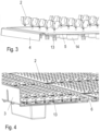
- the shell 3 can, for example in the Fig. 2 and 4 shown, have a stiffening projection 6 which, as shown, extends over the length of the shell 3. Corresponding stiffening projections 6 can also be provided in the width direction.
- the length and/or the width of the stiffening projections 6 must of course be taken into account when dimensioning the receiving space as a multiple of the width and/or length of the plant mat supports 4.
- the plant mat carrier 4 is buoyant. So if a liquid is filled into the bowl 3, the planting mat carrier 4 floats before the liquid reaches the planting mat 5. However, the plants have roots 13 which protrude through the plant mat support 4 and can thus get into the liquid.
- the planting mat carrier 4 floats to such an extent that there is always a certain distance between the planting mat 5 and the liquid, so that the roots 13 can also be supplied with oxygen from the air.
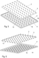
- the buoyancy of the planting mat carrier 4 is achieved in particular by floating bodies 14, which are arranged on the underside (in the direction of gravity) of the planting mat carrier 4. How to in particular Fig. 6 can recognize, the planting mat carrier 4 has a plurality of floating bodies 14, which are arranged symmetrically distributed over the surface of the planting mat carrier 4.
- the floating bodies 14 are formed in one piece with the planting mat carrier 4, in particular by shaping the planting mat carrier 4.
- the shapes that form the floating bodies 14 are pot-shaped, that is, they also form a recess 15 ( Fig. 5 ) on the top of the planting mat carrier 4.
- the planting mat carrier 4 can be easily formed as a deep-drawn part, for example from a metal sheet or from a plastic plate.
- the planting mat carrier has a plurality of through openings 16 through which the roots 13 can protrude into the liquid below the planting mat carrier 4.
- a through opening 16 is arranged in an area at each end of which a floating body 14 is arranged. However, this does not apply to the corners and edges of the planting mat carrier 4.
- the planting mat carrier 4 has a circumferential positioning stop 17 on its edge.
- the positioning stop 17 serves as a boundary of a planting mat support surface 18 on which the planting mat 5 is placed.
- the planting mat support surface 18 has the same size as the planting mat 5.
- the positioning stop 17 thus forms a positioning aid when placing the planting mat 5 on the planting mat carrier 4.
- plants 2 are to grow in the device 1, then in a first step inside or outside the device 1 seeds or seedlings are placed on the planting mat 5 and germinated there.
- the planting mat 5 can be equipped with seeds or seedlings automatically, in a grid that corresponds to the through openings 16.
- the planting mats 5 with the pre-germinated plants 2 are then applied to the planting mat supports 4 and the planting mat supports 4 are placed in the tray 3.
- the trays 3 can then be placed in the greenhouse and, if the greenhouse is a block storage arrangement, stacked.
- the above-mentioned lighting devices provide the light required for growing. Liquid with appropriate nutrients is supplied and removed via the liquid inflow 7 and the liquid outflow 8. There are no particularly high demands on the control of the liquid level in the bowl 3, since the plant mat supports 4 float. If enough liquid is filled into the bowl 3, it cannot happen that the liquid floods the planting mats 5 and washes the planting mats 5 away from the planting mat carriers 4. However, the roots 13 can protrude into the liquid and absorb liquid and nutrients there.
- the plant mat supports 4 are placed back on the bottom of the bowl 3. Even if the bowl 3 is not aligned exactly horizontally, there is no problem that some plants are over-supplied and other plants are under-supplied. Due to the buoyancy of the planting mat carrier, the planting mat carrier 4 aligns itself with its planting mat support surface 18 exactly parallel to the surface of the liquid, so that the plants 2 located on a planting mat carrier 4 all have the same conditions.
- the planting mats can be made from a fleece, for example.
- the plant mat carrier 4 is reusable.
Landscapes
- Life Sciences & Earth Sciences (AREA)
- Environmental Sciences (AREA)
- Hydroponics (AREA)
- Cultivation Receptacles Or Flower-Pots, Or Pots For Seedlings (AREA)
Abstract
Es wird eine Vorrichtung (1) zur Aufzucht von Pflanzen (2) mit einem Pflanzmattenträger (4), der eine Pflanzmatten-Auflagefläche aufweist, und eine Schale (3) angegeben, in der der Pflanzmattenträger (4) angeordnet ist.
Man möchte die Aufzucht von Pflanzen in einem Gewächshaus mit einfachen Mitteln wenig störanfällig gestalten können.
Hierzu ist vorgesehen, dass der Pflanzmattenträger (4) schwimmfähig ist.
Description
- Die vorliegende Erfindung betrifft eine Vorrichtung zur Aufzucht von Pflanzen mit einem Pflanzmattenträger, der eine Pflanzmatten-Auflagefläche aufweist, und mit einer Schale, in der der Pflanzmattenträger angeordnet ist.
- Eine derartige Vorrichtung wird insbesondere verwendet, wenn man Pflanzen in einem Gewächshaus aufziehen möchte. Das Gewächshaus kann dabei auch als Blocklageranordnung ausgebildet sein, bei der die Schalen mit einem gewissen Abstand übereinandergestapelt werden. Die Schalen, ggfs. bis auf die unterste Schale, weisen an ihrer Unterseite dann entsprechende Beleuchtungseinrichtungen auf, um die Pflanzen in der jeweils darunter befindlichen Schale beleuchten zu können.
- Um die Aufzucht der Pflanzen mit möglichst wenig Aufwand durchführen zu können, werden vielfach Samen oder Keimlinge auf Pflanzmatten aufgebracht, wo man sie bis zu einem gewissen Stadium vorkeimen lässt. Die sich entwickelnden Pflanzen haben dann schon Wurzeln, die die Pflanzmatten durchdringen. Die Pflanzmatten sind oder werden dann in eine Schale eingebracht, in der sie mit Flüssigkeit und Nährstoffen versorgt werden.
- Ein gewisses Problem besteht darin, die Versorgung der Pflanzen in den Pflanzmatten so zu gestalten, dass die Pflanzen nicht zu viel, aber auch nicht zu wenig Flüssigkeit erhalten. Dies ist insbesondere dann schwierig, wenn die Schalen nicht exakt horizontal ausgerichtet werden. In diesem Fall steht die Flüssigkeit "schief" in der Schale, so dass einige Pflanzen zu viel Wasser erhalten und andere Pflanzen zu wenig Wasser erhalten. In jedem Fall ist hier eine sehr genaue Steuerung der Zufuhr der Flüssigkeit erforderlich. Dies macht die Aufzucht von Pflanzen in einem Gewächshaus aufwändig.
- Der Erfindung liegt die Aufgabe zugrunde, die Aufzucht von Pflanzen in einem Gewächshaus, insbesondere in einem Blocklager-Gewächshaus, mit einfachen Mitteln wenig störanfällig zu gestalten.
- Diese Aufgabe wird dadurch gelöst, dass der Pflanzmattenträger schwimmfähig ist.
- Der Pflanzmattenträger kann dann in die Schale eingelegt werden, wobei vor oder nach dem Einlegen des Pflanzmattenträgers in die Schale eine Pflanzmatte auf die Auflagefläche aufgelegt wird. Wenn nun Flüssigkeit in die Schale eingefüllt wird, dann schwimmt der Pflanzmattenträger auf. Dies hat den Vorteil, dass die Pflanzen auf dem Pflanzmattenträger nicht überflutet werden können. Der Pflanzmattenträger sorgt immer für eine korrekte Positionierung der Pflanzen auf dem Pflanzmattenträger in Bezug auf die Oberfläche der Flüssigkeit. Weiterhin hat diese Ausgestaltung den Vorteil, dass auch bei Schalen, die nicht exakt horizontal ausgerichtet sind, alle Pflanzen gleichermaßen mit der Flüssigkeit versorgt werden. Es gibt also keine Bereiche, die trockener oder nasser sind. Vielmehr richtet sich der Pflanzmattenträger automatisch in Bezug auf die Flüssigkeitsoberfläche so aus, dass alle Pflanzen gleichmäßig versorgt werden.
- Vorzugsweise weist die Schale mindestens einen Flüssigkeitszufluss und mindestens einen Flüssigkeitsabfluss auf. Man kann dann die Bewässerung der Pflanzen in der Schale automatisieren.
- Vorzugsweise weist der Pflanzmattenträger an seiner in Schwerkraftrichtung unten angeordneten Seite mindestens einen Schwimmkörper auf. Der Schwimmkörper sorgt dann für die Schwimmfähigkeit des Pflanzmattenträgers. Durch den Schwimmkörper ist man bei der Wahl des Materials für den Pflanzmattenträger freier. Man kann also auch Materialien verwenden, die ein größeres spezifisches Gewicht als die Flüssigkeit, insbesondere als Wasser, aufweisen. Die Schwimmfähigkeit wird in diesem Fall durch den Schwimmkörper erreicht oder zumindest unterstützt.
- Vorzugsweise weist der Pflanzmattenträger mehrere Schwimmkörper auf, die symmetrisch über seine Fläche verteilt angeordnet sind. In diesem Fall ist man nicht mehr darauf angewiesen, die Pflanzmatte symmetrisch auf dem Pflanzmattenträger aufzulegen. Vielmehr sorgen die mehreren Schwimmkörper für eine stabile Lagerung des Pflanzmattenträgers auf der Flüssigkeit, die sich in der Schale befindet.
- Vorzugsweise ist der Schwimmkörper einstückig mit dem Pflanzmattenträger ausgebildet. Es besteht damit nicht die Gefahr, dass sich der Schwimmkörper von der Pflanzmatte ablösen kann und die Schwimmfähigkeit verschlechtert wird.
- Auch ist bevorzugt, dass der mindestens eine Schwimmkörper durch eine Ausformung des Pflanzmattenträgers gebildet ist. Dies ist eine relativ einfache Möglichkeit, um den Schwimmkörper einstückig mit dem Rest des Pflanzmattenträgers auszubilden.
- Auch ist von Vorteil, wenn der Pflanzmattenträger als Tiefziehteil ausgebildet ist. Das Tiefziehteil kann dann aus einem flächigen Material, beispielsweise einem Metallblech oder einer Kunststoffplatte, gebildet werden, indem es in eine Presse eingelegt und umgeformt wird. Dadurch lassen sich auf einfache Weise die gewünschten Geometrien erreichen, insbesondere die Ausformung oder die Ausformungen, die später den oder die Schwimmkörper bilden.
- Vorzugsweise weist der Pflanzmattenträger außerhalb des mindestens einen Schwimmkörpers mindestens eine Durchgangsöffnung auf. Durch die Durchgangsöffnung können sich dann die Wurzeln der Pflanzen nach unten erstrecken und die in der Schale befindliche Flüssigkeit erreichen. Es ist nicht mehr notwendig, dass die Wurzeln das Material des Pflanzmattenträgers durchdringen, so dass man wiederum bei der Wahl des Materials für den Pflanzmattenträger eine größere Freiheit hat.
- Bevorzugterweise ist eine Durchgangsöffnung in einem Bereich angeordnet, an dessen Ecken jeweils ein Schwimmkörper angeordnet ist. Der Bereich, in dem die Durchgangsöffnung angeordnet ist, wird also gegenüber der Oberfläche der Flüssigkeit in der Schale stabilisiert.
- Vorzugsweise weist der Pflanzmattenträger mindestens einen Positionieranschlag als Begrenzung der Pflanzmatten-Auflagefläche auf. Die Pflanzmatte kann dann auf dem Pflanzmattenträger nicht verrutschen. Darüber hinaus erhält eine Bedienungsperson eine Hilfe beim Positionieren der Pflanzmatte auf der Auflagefläche.
- Bevorzugterweise weist die Schale einen Pflanzmattenträger-Aufnahmeraum mit einer Länge auf, die einem n-fachen der Länge des Pflanzmattenträgers entspricht, wobei n eine ganze Zahl ist, und/oder die Schale weist einen Pflanzmattenträger-Aufnahmeraum mit einer Breite auf, die einem m-fachen der Breite des Pflanzmattenträgers entspricht, wobei m eine ganze Zahl ist. In diesem Fall ist auch die Position des Pflanzmattenträgers in der Schale festgelegt. Die Breite des Pflanzmattenträgers verläuft parallel zur Breite der Schale und die Länge des Pflanzmattenträgers verläuft parallel zur Länge der Schale. Wenn ein Pflanzmattenträger in die Schale eingelegt wird und der Pflanzmattenträger-Aufnahmeraum mit seiner Länge und Breite den Abmessungen des Pflanzmattenträgers entspricht, dann ist der Pflanzmattenträger zuverlässig gehalten. Wenn die Länge und/oder die Breite einem ganzzahligen Vielfachen der Länge und/oder Breite des Pflanzmattenträgers entspricht, dann kann man eben eine entsprechend größere Anzahl von Pflanzmattenträgern in die Schale einlegen, wobei sich die Pflanzmattenträger dann gegenseitig positionieren und auch hier eine Positionsänderung der Pflanzmattenträger in der Schale praktisch unmöglich ist. Auch hier zeigt sich wieder der Vorteil der Schwimmfähigkeit der Pflanzmattenträger. Die Pflanzmattenträger, die gleich aufgebaut sind und dementsprechend gleich schwimmfähig sind, können sich nicht übereinander schieben, wenn Flüssigkeit in die Schale eingefüllt wird.
- Auch ist von Vorteil, dass der Pflanzmattenträger-Aufnahmeraum an mindestens einem Ende einen Anschlag aufweist, der sich in Schwerkraftrichtung nach oben verjüngt. Wenn ein Füllstand der Flüssigkeit in der Schale absinkt, dann gleiten die Pflanzmattenträger in Schwerkraftrichtung nach unten und werden dann durch den sich nach unten verdickenden Anschlag mit geringem Aufwand exakt in ihre Position geführt.
- Vorzugsweise ist mindestens ein Anschlag durch eine Verdickung einer Innenseite einer Wand der Schale gebildet. Der Anschlag kann dann einstückig mit der Wand ausgebildet sein, was die Fertigung der Schale erleichtert.
- Hierbei ist bevorzugt, dass die Wand eine Außenseite aufweist und sich die Verdickung auf der Außenseite fortsetzt. Der Anschlag stabilisiert dann gleichzeitig die Wand der Schale.
- Die Erfindung wird im Folgenden anhand eines bevorzugten Ausführungsbeispiels in Verbindung mit der Zeichnung beschrieben. Hierin zeigen:
- Fig. 1
- eine Schale mit mehreren Pflanzmattenträgern,
- Fig. 2
- die Schale aus
Fig. 1 , teilweise im Schnitt, - Fig. 3
- einen Pflanzmattenträger mit Pflanzmatte und Pflanzen,
- Fig. 4
- den Pflanzmattenträger von
Fig. 3 in der Schale, - Fig. 5
- eine Explosionsdarstellung von Pflanzmattenträger und Pflanzmatte von schräg oben, und
- Fig. 6
- eine Explosionsdarstellung von Pflanzmattenträger und Pflanzmatte von schräg unten.
- Die
Fig. 1 und 2 zeigen eine Vorrichtung 1 zur Aufzucht von Pflanzen 2 mit einer Schale 3. In der Schale 3 sind Pflanzmattenträger 4 (Fig. 3 ) angeordnet. Auf jedem Pflanzmattenträger 4 befindet sich eine Pflanzmatte 5 mit Pflanzen 2, die auf der Pflanzmatte 5 wachsen sollen. - Die Schale 2 weist einen Flüssigkeitszufluss 7 und einen Flüssigkeitsabfluss 8 auf. Der Flüssigkeitsabfluss 8 ist in Wirklichkeit nach unten gerichtet. Der in den
Fig. 1 und 2 dargestellte Flüssigkeitsabfluss ist der Flüssigkeitsabfluss einer im Betrieb oberhalb der dargestellten Schale 3 angeordneten weiteren Schale. - Die Schale 3 weist an ihrer in Schwerkraftrichtung unteren Seite mehrere Kufen 9 und gegebenenfalls nicht dargestellte Beleuchtungskörper auf, mit denen Pflanzen 2 einer Schale 3 beleuchtet werden können, die im Betrieb unterhalb der dargestellten Schale 3 angeordnet sind.
- In der in den
Fig. 1 und 2 dargestellten Schale 3 sind insgesamt acht Pflanzmattenträger montiert und somit auch acht Pflanzmatten 5 angeordnet. Hierzu weist die Schale 3 einen Aufnahmeraum auf, dessen Länge dem 4-fachen der Länge des Pflanzmattenträgers 4 und dessen Breite dem 2-fachen des Pflanzmattenträgers 4 entspricht. Die Länge ist dabei ein Abstand zwischen Anschlägen 10 an einer Längsseite der Schale 3 und die Länge ist der Abstand zwischen entsprechenden Anschlägen an den Schmalseiten der Schale 3. Die Anschläge 10 sind als Verdickungen einer Wand 11 der Schale 3 ausgebildet. Diese Verdickungen setzen sich auf der Außenseite der Schale 3 fort, wie durch das Bezugszeichen 12 angedeutet ist. - Die Schale 3 kann, wie beispielsweise in den
Fig. 2 und4 dargestellt, einen Versteifungsvorsprung 6 aufweisen, der sich, wie dargestellt, über die Länge der Schale 3 erstreckt. Entsprechende Versteifungsvorsprünge 6 können auch in Richtung der Breite vorgesehen sein. - Die Länge und/oder die Breite der Versteifungsvorsprünge 6 sind bei der Bemessung des Aufnahmeraums als Vielfaches der Breite und/oder Länge der Pflanzmattenträger 4 natürlich zu berücksichtigen.
- Der Pflanzmattenträger 4 ist schwimmfähig. Wenn also eine Flüssigkeit in die Schale 3 eingefüllt wird, dann schwimmt der Pflanzmattenträger 4 auf, bevor die Flüssigkeit die Pflanzmatte 5 erreicht. Die Pflanzen weisen allerdings Wurzeln 13 auf, die den Pflanzmattenträger 4 durchragen und somit in die Flüssigkeit gelangen können. Der Pflanzmattenträger 4 schwimmt so weit auf, dass zwischen der Pflanzmatte 5 und der Flüssigkeit immer ein gewisser Abstand vorhanden ist, so dass die Wurzeln 13 auch mit Sauerstoff aus der Luft versorgt werden können.
- Die Schwimmfähigkeit des Pflanzmattenträgers 4 wird insbesondere durch Schwimmkörper 14 bewirkt, die an der Unterseite (in Schwerkraftrichtung) des Pflanzmattenträgers 4 angeordnet sind. Wie man insbesondere in
Fig. 6 erkennen kann, weist der Pflanzmattenträger 4 eine Vielzahl von Schwimmkörpern 14 auf, die symmetrisch über die Fläche des Pflanzmattenträgers 4 verteilt angeordnet sind. - Die Schwimmkörper 14 sind einstückig mit dem Pflanzmattenträger 4 ausgebildet, insbesondere durch eine Ausformung des Pflanzmattenträgers 4. Die Ausformungen, die die Schwimmkörper 14 bilden, sind topfartig ausgebildet, d.h. sie bilden auch eine Vertiefung 15 (
Fig. 5 ) an der Oberseite des Pflanzmattenträgers 4. Der Pflanzmattenträger 4 lässt sich auf einfache Weise als Tiefziehteil ausbilden, beispielsweise aus einem Metallblech oder aus einer Kunststoffplatte. - Wie man insbesondere in den
Fig. 5 und 6 erkennen kann, weist der Pflanzmattenträger eine Vielzahl von Durchgangsöffnungen 16 auf, durch die die Wurzeln 13 in die Flüssigkeit unterhalb des Pflanzmattenträgers 4 ragen können. Eine Durchgangsöffnung 16 ist in den meisten Fällen in einem Bereich angeordnet, an dessen Enden jeweils ein Schwimmkörper 14 angeordnet ist. Dies gilt allerdings nicht in den Ecken und den Rändern des Pflanzmattenträgers 4. - Der Pflanzmattenträger 4 weist einen umlaufenden Positionieranschlag 17 an seinem Rand auf. Der Positionieranschlag 17 dient als Begrenzung einer Pflanzmatten-Auflagefläche 18, auf den die Pflanzmatte 5 aufgelegt wird. Die Pflanzmatten-Auflagefläche 18 hat die gleiche Größe, wie die Pflanzmatte 5. Damit bildet der Positionieranschlag 17 eine Positionierhilfe beim Auflegen der Pflanzmatte 5 auf dem Pflanzmattenträger 4.
- Wenn Pflanzen 2 in der Vorrichtung 1 wachsen sollen, dann werden in einem ersten Schritt innerhalb oder außerhalb der Vorrichtung 1 Samen oder Keimlinge auf die Pflanzmatte 5 aufgebracht und dort zum Keimen gebracht. Die Bestückung der Pflanzmatte 5 mit dem Samen oder Keimlingen kann automatisch erfolgen, und zwar in einem Raster, das den Durchgangsöffnungen 16 entspricht. Die Pflanzmatten 5 mit den vorgekeimten Pflanzen 2 werden dann auf die Pflanzmattenträger 4 aufgebracht und die Pflanzmattenträger 4 werden in die Schale 3 eingelegt. Die Schalen 3 können dann in das Gewächshaus verbracht werden und, wenn es sich bei dem Gewächshaus um eine Blocklageranordnung handelt, gestapelt werden.
- Durch die oben erwähnten Beleuchtungseinrichtungen wird das zum Wachsen erforderliche Licht bereitgestellt. Über den Flüssigkeitszufluss 7 und den Flüssigkeitsabfluss 8 wird Flüssigkeit mit entsprechenden Nährstoffen zu- und abgeführt. Dabei muss man an die Steuerung der Flüssigkeitshöhe in der Schale 3 keine besonders großen Anforderungen stellen, da die Pflanzmattenträger 4 aufschwimmen. Wenn genügend Flüssigkeit in die Schale 3 eingefüllt wird, kann es nicht vorkommen, dass die Flüssigkeit die Pflanzmatten 5 überflutet und die Pflanzmatten 5 von den Pflanzmattenträgern 4 wegschwemmt. Die Wurzeln 13 können jedoch in die Flüssigkeit hineinragen und dort Flüssigkeit und Nährstoffe aufnehmen.
- Wenn die Flüssigkeit aus der Schale abgelassen wird, dann setzen sich die Pflanzmattenträger 4 wieder auf dem Boden der Schale 3 auf. Auch dann, wenn die Schale 3 nicht genau horizontal ausgerichtet ist, besteht kein Problem, dass einige Pflanzen überversorgt und andere Pflanzen unterversorgt werden. Durch die Schwimmfähigkeit des Pflanzmattenträgers richtet sich der Pflanzmattenträger 4 mit seiner Pflanzmatten-Auflagefläche 18 genau parallel zur Oberfläche der Flüssigkeit aus, so dass die auf einem Pflanzmattenträger 4 befindlichen Pflanzen 2 alle die gleichen Bedingungen haben.
- Die Pflanzmatten können beispielsweise aus einem Vlies gebildet sein. Der Pflanzmattenträger 4 ist wiederverwendbar.
Claims (14)
- Vorrichtung (1) zur Aufzucht von Pflanzen (2) mit einem Pflanzmattenträger (4), der eine Pflanzmatten-Auflagefläche (18) aufweist, und mit einer Schale (3), in der der Pflanzmattenträger (4) angeordnet ist, dadurch gekennzeichnet, dass der Pflanzmattenträger (4) schwimmfähig ist, wobei der Pflanzmattenträger (4) an seiner in Schwerkraftrichtung unten angeordneten Seite mindestens einen Schwimmkörper (14) aufweist.
- Vorrichtung nach Anspruch 1, dadurch gekennzeichnet, dass die Schale (3) mindestens einen Flüssigkeitszufluss (7) und mindestens einen Flüssigkeitsabfluss aufweist.
- Vorrichtung nach Anspruch 1 oder 2, dadurch gekennzeichnet, dass der Pflanzmattenträger (4) mehrere Schwimmkörper (14) aufweist, die symmetrisch über seine Fläche verteilt angeordnet sind.
- Vorrichtung nach einem der Ansprüche 1 bis 3, dadurch gekennzeichnet, dass der mindestens eine Schwimmkörper (14) einstückig mit dem Pflanzmattenträger (4) ausgebildet ist.
- Vorrichtung nach Anspruch 4, dadurch gekennzeichnet, dass der mindestens eine Schwimmkörper (14) durch eine Ausformung des Pflanzmattenträgers (4) gebildet ist.
- Vorrichtung nach Anspruch 5, dadurch gekennzeichnet, dass die Ausformung topfartig ausgebildet ist.
- Vorrichtung nach einem der Ansprüche 1 bis 4, dadurch gekennzeichnet, dass der Pflanzmattenträger (4) als Tiefziehteil ausgebildet ist.
- Vorrichtung nach einem der Ansprüche 1 bis 7, dadurch gekennzeichnet, dass der Pflanzmattenträger (4) außerhalb des mindestens einen Schwimmkörpers (14) mindestens eine Durchgangsöffnung (16) aufweist.
- Vorrichtung nach Anspruch 8, dadurch gekennzeichnet, dass eine Durchgangsöffnung (16) in einem Bereich angeordnet ist, an dessen Ecken jeweils ein Schwimmkörper (14) angeordnet ist.
- Vorrichtung nach einem der Ansprüche 1 bis 9, dadurch gekennzeichnet, dass der Pflanzmattenträger (4) mindestens einen Positionieranschlag (17) als Begrenzung der Pflanzmatten-Auflagefläche (18) aufweist.
- Vorrichtung nach einem der Ansprüche 1 bis 10, dadurch gekennzeichnet, dass die Schale (3) einen Pflanzmattenträger-Aufnahmeraum mit einer Länge aufweist, die einem n-fachen der Länge des Pflanzmattenträgers (4) entspricht, wobei n eine ganze Zahl ist, und/oder die Schale (3) einen Pflanzmattenträger-Aufnahmeraum mit einer Breite aufweist, die einem m-fachen der Breite des Pflanzmattenträgers (4) entspricht, wobei m eine ganze Zahl ist.
- Vorrichtung nach Anspruch 11, dadurch gekennzeichnet, dass der Pflanzmattenträger-Aufnahmeraum an mindestens einem Ende einen Anschlag (10) aufweist, der sich in Schwerkraftrichtung nach oben verjüngt.
- Vorrichtung nach Anspruch 12, dadurch gekennzeichnet, dass mindestens ein Anschlag (10) durch eine Verdickung einer Innenseite einer Wand (11) der Schale (3) gebildet ist.
- Vorrichtung nach Anspruch 13, dadurch gekennzeichnet, dass die Wand (11) eine Außenseite (6) aufweist und sich die Verdickung (12) auf der Außenseite (6) fortsetzt.
Priority Applications (5)
| Application Number | Priority Date | Filing Date | Title |
|---|---|---|---|
| EP22180324.0A EP4295671A1 (de) | 2022-06-22 | 2022-06-22 | Vorrichtung zur aufzucht von pflanzen |
| JP2023099854A JP2024001868A (ja) | 2022-06-22 | 2023-06-19 | 植物を栽培するための装置 |
| CN202310731560.3A CN117256462A (zh) | 2022-06-22 | 2023-06-20 | 用于培育植物的装置 |
| US18/212,407 US20230413747A1 (en) | 2022-06-22 | 2023-06-21 | Apparatus for growing plants |
| CA3204270A CA3204270A1 (en) | 2022-06-22 | 2023-06-21 | Apparatus for growing plants |
Applications Claiming Priority (1)
| Application Number | Priority Date | Filing Date | Title |
|---|---|---|---|
| EP22180324.0A EP4295671A1 (de) | 2022-06-22 | 2022-06-22 | Vorrichtung zur aufzucht von pflanzen |
Publications (1)
| Publication Number | Publication Date |
|---|---|
| EP4295671A1 true EP4295671A1 (de) | 2023-12-27 |
Family
ID=82214504
Family Applications (1)
| Application Number | Title | Priority Date | Filing Date |
|---|---|---|---|
| EP22180324.0A Pending EP4295671A1 (de) | 2022-06-22 | 2022-06-22 | Vorrichtung zur aufzucht von pflanzen |
Country Status (5)
| Country | Link |
|---|---|
| US (1) | US20230413747A1 (de) |
| EP (1) | EP4295671A1 (de) |
| JP (1) | JP2024001868A (de) |
| CN (1) | CN117256462A (de) |
| CA (1) | CA3204270A1 (de) |
Families Citing this family (1)
| Publication number | Priority date | Publication date | Assignee | Title |
|---|---|---|---|---|
| US12439859B2 (en) * | 2020-03-05 | 2025-10-14 | Yeshealth Agri-Biotechnology Co., Ltd. | Stackable raising seedling device and method using the same |
Citations (4)
| Publication number | Priority date | Publication date | Assignee | Title |
|---|---|---|---|---|
| WO2012050449A1 (en) * | 2010-10-15 | 2012-04-19 | Holding B.V.Jalmaja | Cultivation assembly and method for growing crops |
| WO2021072550A1 (en) * | 2019-10-16 | 2021-04-22 | Inventive Laboratory Inc. | Growing system and apparatus |
| DE102020125904A1 (de) * | 2020-10-02 | 2022-04-07 | &Ever Gmbh | Trägersystem für eine automatisierte Aufzucht von Pflanzen |
| US20220132750A1 (en) * | 2020-03-05 | 2022-05-05 | Yeshealth Agri-Biotechnology Co., Ltd. | Stackable raising seedling device and method using the same |
Family Cites Families (13)
| Publication number | Priority date | Publication date | Assignee | Title |
|---|---|---|---|---|
| US4312152A (en) * | 1980-06-09 | 1982-01-26 | Agrownautics, Inc. | Buoyant support structure and system and method using structure for water culture of plants |
| JPH086445Y2 (ja) * | 1991-03-08 | 1996-02-28 | 積水化成品工業株式会社 | 水耕栽培用栽培物保持器 |
| US5324657A (en) * | 1992-04-21 | 1994-06-28 | Osmotek Ltd. | Apparatus for plant cell tissue culture |
| US8549788B2 (en) * | 2012-03-06 | 2013-10-08 | Mb3, L.L.C. | Hydroponic growing system |
| WO2014077682A1 (en) * | 2012-11-13 | 2014-05-22 | Jalmaja Holding B.V. | Growing system and method for growing plants on water |
| BR112016002932B1 (pt) * | 2013-08-14 | 2021-02-23 | Yugenkaisha Japan Tsusyo | sistema de cultivo hidropônico |
| NL2013161B1 (en) * | 2014-07-10 | 2016-09-20 | Cultivation Systems B V | Method for the cultivation of plants using a carrier with a removable side support structure arranged thereon. |
| SG11201806554UA (en) * | 2016-03-31 | 2018-10-30 | Sekisui Chemical Co Ltd | Hydroponic system using seawater and cultivation system for growing seeds and seedlings |
| US10383292B2 (en) * | 2016-06-06 | 2019-08-20 | Double J Holdings, LLC | System and method for cultivating plants |
| TW201831078A (zh) * | 2017-02-17 | 2018-09-01 | 先端農業科技股份有限公司 | 水耕植物栽培系統及其應用方法 |
| JP6845432B2 (ja) * | 2017-08-10 | 2021-03-17 | トーホー工業株式会社 | フロート体 |
| US12048276B2 (en) * | 2020-02-20 | 2024-07-30 | Hippo Harvest Inc. | Growspace automation |
| CN214282626U (zh) * | 2021-01-19 | 2021-09-28 | 河南城建学院 | 一种水生景观植物的景观浮台结构 |
-
2022
- 2022-06-22 EP EP22180324.0A patent/EP4295671A1/de active Pending
-
2023
- 2023-06-19 JP JP2023099854A patent/JP2024001868A/ja active Pending
- 2023-06-20 CN CN202310731560.3A patent/CN117256462A/zh active Pending
- 2023-06-21 CA CA3204270A patent/CA3204270A1/en active Pending
- 2023-06-21 US US18/212,407 patent/US20230413747A1/en active Pending
Patent Citations (4)
| Publication number | Priority date | Publication date | Assignee | Title |
|---|---|---|---|---|
| WO2012050449A1 (en) * | 2010-10-15 | 2012-04-19 | Holding B.V.Jalmaja | Cultivation assembly and method for growing crops |
| WO2021072550A1 (en) * | 2019-10-16 | 2021-04-22 | Inventive Laboratory Inc. | Growing system and apparatus |
| US20220132750A1 (en) * | 2020-03-05 | 2022-05-05 | Yeshealth Agri-Biotechnology Co., Ltd. | Stackable raising seedling device and method using the same |
| DE102020125904A1 (de) * | 2020-10-02 | 2022-04-07 | &Ever Gmbh | Trägersystem für eine automatisierte Aufzucht von Pflanzen |
Also Published As
| Publication number | Publication date |
|---|---|
| JP2024001868A (ja) | 2024-01-10 |
| CA3204270A1 (en) | 2023-12-22 |
| US20230413747A1 (en) | 2023-12-28 |
| CN117256462A (zh) | 2023-12-22 |
Similar Documents
| Publication | Publication Date | Title |
|---|---|---|
| DE102015004112B3 (de) | Säulenelement für eine Vorrichtung zum vertikalen Anbau von Pflanzen | |
| DE3047646C2 (de) | ||
| DE2612561A1 (de) | Vorrichtung zur bewaesserung von blumen oder pflanzen in blumentoepfen oder blumenkaesten | |
| DE3732119A1 (de) | Vorrichtung zur anpflanzung von blumen in mehreren ebenen | |
| DE102014111425A1 (de) | Pflanzentopfgruppe mit kontrollierbarer Bewässerungswasserstromteilung | |
| DE3012874A1 (de) | Pflanzentopf | |
| EP3319414B1 (de) | Palette für pflanztopfe | |
| DE69110693T2 (de) | Keimbehälter. | |
| DE3718112C2 (de) | Gartenbauvorrichtung fuer das aufziehen von pflanzen | |
| WO2024056384A1 (de) | Haltevorrichtung für mindestens ein saatkorn und eine daraus wachsende pflanze | |
| DE202022101083U1 (de) | Überlaufdorn für einen Behälter zum Anzüchten von Blumenzwiebeln | |
| EP0988783B1 (de) | Kulturplatte zum Bewurzeln von Jungpflanzen | |
| DE2610613A1 (de) | Bewaesserungs-vorrichtung fuer topfpflanzen | |
| CH665748A5 (de) | Blumentopf. | |
| DE3238594A1 (de) | Vorrichtung zur anzucht von saemlingen | |
| DE1030096B (de) | Bewaesserungsvorrichtung fuer Topfpflanzen | |
| DE69830194T2 (de) | Topf mit bein | |
| WO2015121094A1 (de) | Pflanzbeet-vorrichtung | |
| DE3539460A1 (de) | Vegetationswand | |
| DE102005041797B3 (de) | Formkörper zur Verhinderung von Staunässe in Pflanzgefäßen | |
| DE29919154U1 (de) | Blumen- und Pflanzgefäß | |
| DE102016117750A1 (de) | Wasserstands-regelungseinrichtung | |
| DE20121708U1 (de) | Vorrichtung zum oberflächennahen Wasserabzug, insbesondere bei der Abwassertechnik | |
| DE69501070T2 (de) | Vorrichtung zum Bewässern von Blumentöpfen | |
| EP4385317A1 (de) | Pflanzmodul für einen hängenden garten |
Legal Events
| Date | Code | Title | Description |
|---|---|---|---|
| PUAI | Public reference made under article 153(3) epc to a published international application that has entered the european phase |
Free format text: ORIGINAL CODE: 0009012 |
|
| STAA | Information on the status of an ep patent application or granted ep patent |
Free format text: STATUS: REQUEST FOR EXAMINATION WAS MADE |
|
| 17P | Request for examination filed |
Effective date: 20230214 |
|
| AK | Designated contracting states |
Kind code of ref document: A1 Designated state(s): AL AT BE BG CH CY CZ DE DK EE ES FI FR GB GR HR HU IE IS IT LI LT LU LV MC MK MT NL NO PL PT RO RS SE SI SK SM TR |
|
| STAA | Information on the status of an ep patent application or granted ep patent |
Free format text: STATUS: EXAMINATION IS IN PROGRESS |
|
| 17Q | First examination report despatched |
Effective date: 20240924 |