EP4294594B1 - Methode zum betrieb einer laserbearbeitungsmaschine von rohren oder profilen mit einem in der maschine integrierten system zur automatisierten einbringung von gewindeeinsätzen - Google Patents
Methode zum betrieb einer laserbearbeitungsmaschine von rohren oder profilen mit einem in der maschine integrierten system zur automatisierten einbringung von gewindeeinsätzen Download PDFInfo
- Publication number
- EP4294594B1 EP4294594B1 EP22706122.3A EP22706122A EP4294594B1 EP 4294594 B1 EP4294594 B1 EP 4294594B1 EP 22706122 A EP22706122 A EP 22706122A EP 4294594 B1 EP4294594 B1 EP 4294594B1
- Authority
- EP
- European Patent Office
- Prior art keywords
- insert
- picking
- tube
- threaded
- riveter
- Prior art date
- Legal status (The legal status is an assumption and is not a legal conclusion. Google has not performed a legal analysis and makes no representation as to the accuracy of the status listed.)
- Active
Links
Images




Classifications
-
- B—PERFORMING OPERATIONS; TRANSPORTING
- B23—MACHINE TOOLS; METAL-WORKING NOT OTHERWISE PROVIDED FOR
- B23K—SOLDERING OR UNSOLDERING; WELDING; CLADDING OR PLATING BY SOLDERING OR WELDING; CUTTING BY APPLYING HEAT LOCALLY, e.g. FLAME CUTTING; WORKING BY LASER BEAM
- B23K26/00—Working by laser beam, e.g. welding, cutting or boring
- B23K26/36—Removing material
- B23K26/38—Removing material by boring or cutting
-
- B—PERFORMING OPERATIONS; TRANSPORTING
- B21—MECHANICAL METAL-WORKING WITHOUT ESSENTIALLY REMOVING MATERIAL; PUNCHING METAL
- B21J—FORGING; HAMMERING; PRESSING METAL; RIVETING; FORGE FURNACES
- B21J15/00—Riveting
- B21J15/10—Riveting machines
- B21J15/14—Riveting machines specially adapted for riveting specific articles, e.g. brake lining machines
- B21J15/142—Aerospace structures
-
- B—PERFORMING OPERATIONS; TRANSPORTING
- B21—MECHANICAL METAL-WORKING WITHOUT ESSENTIALLY REMOVING MATERIAL; PUNCHING METAL
- B21J—FORGING; HAMMERING; PRESSING METAL; RIVETING; FORGE FURNACES
- B21J15/00—Riveting
- B21J15/10—Riveting machines
- B21J15/30—Particular elements, e.g. supports; Suspension equipment specially adapted for portable riveters
- B21J15/32—Devices for inserting or holding rivets in position with or without feeding arrangements
-
- B—PERFORMING OPERATIONS; TRANSPORTING
- B23—MACHINE TOOLS; METAL-WORKING NOT OTHERWISE PROVIDED FOR
- B23K—SOLDERING OR UNSOLDERING; WELDING; CLADDING OR PLATING BY SOLDERING OR WELDING; CUTTING BY APPLYING HEAT LOCALLY, e.g. FLAME CUTTING; WORKING BY LASER BEAM
- B23K26/00—Working by laser beam, e.g. welding, cutting or boring
- B23K26/0093—Working by laser beam, e.g. welding, cutting or boring combined with mechanical machining or metal-working covered by other subclasses than B23K
-
- B—PERFORMING OPERATIONS; TRANSPORTING
- B23—MACHINE TOOLS; METAL-WORKING NOT OTHERWISE PROVIDED FOR
- B23K—SOLDERING OR UNSOLDERING; WELDING; CLADDING OR PLATING BY SOLDERING OR WELDING; CUTTING BY APPLYING HEAT LOCALLY, e.g. FLAME CUTTING; WORKING BY LASER BEAM
- B23K26/00—Working by laser beam, e.g. welding, cutting or boring
- B23K26/08—Devices involving relative movement between laser beam and workpiece
- B23K26/083—Devices involving movement of the workpiece in at least one axial direction
- B23K26/0838—Devices involving movement of the workpiece in at least one axial direction by using an endless conveyor belt
- B23K26/0846—Devices involving movement of the workpiece in at least one axial direction by using an endless conveyor belt for moving elongated workpieces longitudinally, e.g. wire or strip material
-
- B—PERFORMING OPERATIONS; TRANSPORTING
- B23—MACHINE TOOLS; METAL-WORKING NOT OTHERWISE PROVIDED FOR
- B23K—SOLDERING OR UNSOLDERING; WELDING; CLADDING OR PLATING BY SOLDERING OR WELDING; CUTTING BY APPLYING HEAT LOCALLY, e.g. FLAME CUTTING; WORKING BY LASER BEAM
- B23K26/00—Working by laser beam, e.g. welding, cutting or boring
- B23K26/08—Devices involving relative movement between laser beam and workpiece
- B23K26/0869—Devices involving movement of the laser head in at least one axial direction
- B23K26/0876—Devices involving movement of the laser head in at least one axial direction in at least two axial directions
-
- B—PERFORMING OPERATIONS; TRANSPORTING
- B23—MACHINE TOOLS; METAL-WORKING NOT OTHERWISE PROVIDED FOR
- B23K—SOLDERING OR UNSOLDERING; WELDING; CLADDING OR PLATING BY SOLDERING OR WELDING; CUTTING BY APPLYING HEAT LOCALLY, e.g. FLAME CUTTING; WORKING BY LASER BEAM
- B23K26/00—Working by laser beam, e.g. welding, cutting or boring
- B23K26/36—Removing material
- B23K26/38—Removing material by boring or cutting
- B23K26/382—Removing material by boring or cutting by boring
-
- B—PERFORMING OPERATIONS; TRANSPORTING
- B23—MACHINE TOOLS; METAL-WORKING NOT OTHERWISE PROVIDED FOR
- B23P—METAL-WORKING NOT OTHERWISE PROVIDED FOR; COMBINED OPERATIONS; UNIVERSAL MACHINE TOOLS
- B23P23/00—Machines or arrangements of machines for performing specified combinations of different metal-working operations not covered by a single other subclass
- B23P23/04—Machines or arrangements of machines for performing specified combinations of different metal-working operations not covered by a single other subclass for both machining and other metal-working operations
-
- B—PERFORMING OPERATIONS; TRANSPORTING
- B25—HAND TOOLS; PORTABLE POWER-DRIVEN TOOLS; MANIPULATORS
- B25B—TOOLS OR BENCH DEVICES NOT OTHERWISE PROVIDED FOR, FOR FASTENING, CONNECTING, DISENGAGING, OR HOLDING
- B25B27/00—Hand tools, specially adapted for fitting together or separating parts or objects whether or not involving some deformation, not otherwise provided for
- B25B27/0007—Tools for fixing internally screw-threaded tubular fasteners
- B25B27/0014—Tools for fixing internally screw-threaded tubular fasteners motor-driven
-
- F—MECHANICAL ENGINEERING; LIGHTING; HEATING; WEAPONS; BLASTING
- F16—ENGINEERING ELEMENTS AND UNITS; GENERAL MEASURES FOR PRODUCING AND MAINTAINING EFFECTIVE FUNCTIONING OF MACHINES OR INSTALLATIONS; THERMAL INSULATION IN GENERAL
- F16B—DEVICES FOR FASTENING OR SECURING CONSTRUCTIONAL ELEMENTS OR MACHINE PARTS TOGETHER, e.g. NAILS, BOLTS, CIRCLIPS, CLAMPS, CLIPS OR WEDGES; JOINTS OR JOINTING
- F16B37/00—Nuts or like thread-engaging members
- F16B37/04—Devices for fastening nuts to surfaces, e.g. sheets, plates
- F16B37/06—Devices for fastening nuts to surfaces, e.g. sheets, plates by means of welding or riveting
- F16B37/062—Devices for fastening nuts to surfaces, e.g. sheets, plates by means of welding or riveting by means of riveting
- F16B37/065—Devices for fastening nuts to surfaces, e.g. sheets, plates by means of welding or riveting by means of riveting by deforming the material of the nut
- F16B37/067—Devices for fastening nuts to surfaces, e.g. sheets, plates by means of welding or riveting by means of riveting by deforming the material of the nut the material of the nut being deformed by a threaded member generating axial movement of the threaded part of the nut, e.g. blind rivet type
-
- B—PERFORMING OPERATIONS; TRANSPORTING
- B23—MACHINE TOOLS; METAL-WORKING NOT OTHERWISE PROVIDED FOR
- B23K—SOLDERING OR UNSOLDERING; WELDING; CLADDING OR PLATING BY SOLDERING OR WELDING; CUTTING BY APPLYING HEAT LOCALLY, e.g. FLAME CUTTING; WORKING BY LASER BEAM
- B23K2101/00—Articles made by soldering, welding or cutting
- B23K2101/04—Tubular or hollow articles
- B23K2101/06—Tubes
-
- B—PERFORMING OPERATIONS; TRANSPORTING
- B23—MACHINE TOOLS; METAL-WORKING NOT OTHERWISE PROVIDED FOR
- B23K—SOLDERING OR UNSOLDERING; WELDING; CLADDING OR PLATING BY SOLDERING OR WELDING; CUTTING BY APPLYING HEAT LOCALLY, e.g. FLAME CUTTING; WORKING BY LASER BEAM
- B23K2101/00—Articles made by soldering, welding or cutting
- B23K2101/28—Beams
Definitions
- This invention relates to a machine for the laser cutting of tubes and profiled sections.
- tube and “profiled section” are used to identify any elongated article having (barring machining tolerances) a uniform cross section along its longitudinal axis, the cross section being of any shape, whether closed (e.g., circular, rectangular, or square) or open (e.g., L, C, U, etc.).
- longitudinal and “transverse” are used to identify the direction of the longitudinal axis of the tube or profiled section and respectively a direction orthogonal to the longitudinal direction.
- DE 102016106067 A1 describes a machine for the laser cutting of tubes or profiled sections configured to make threaded holes.
- the object of this invention is to provide a solution for reducing the production time of tubes and profiled sections equipped with threaded inserts.
- the machine for the laser machining of tubes and profiled sections that is the subject of this invention is described and illustrated herein with reference to its application for machining tubes, but it is understood that it is equally usable for machining profiled sections.
- the tubes or profiled sections on which the machine is able to work may have cross sections of different shapes and sizes.
- a machine for the laser machining of tubes comprises, in a manner known per se, a base 10, a working head 12 adapted to carry out a laser cutting process on a tube T (shown in Fig. 2 to 8 ), a supply device (not shown) adapted to advance the tube T along a longitudinal direction x (coincident with the direction of the longitudinal axis of the tube T and orthogonal to the page of the drawings of Fig. 2 to 8 ), a guide device (not shown) adapted to guide the tube T as it is moved forward by the supply device, and a scanning system (not shown) adapted to scan at least one portion (e.g., an upper portion) of the profile of the cross section of the tube T.
- the working head 12 comprises, in a manner known per se, a focusing device 18 adapted to emit a laser beam focused on the surface of the tube T.
- the working head 12 is carried by a head support structure 26.
- the head support structure 26, and thus with it also the working head 12, is mounted on a carriage 28 so as to be movable in the vertical direction (direction z).
- the carriage 28 is mounted so as to be translatable in a transverse direction (direction y) relative to the base 10 of the machine.
- the transverse direction y is a horizontal direction, it could also be a direction inclined at a certain angle to the horizontal (while obviously lying in a plane perpendicular to the longitudinal axis of the tube).
- the working head 12 is movable in the vertical transverse plane, i.e., in a plane perpendicular to the longitudinal axis x of the tube T, with two degrees of freedom, namely, with one degree of freedom of translation in the vertical direction and with one degree of freedom of translation in the transverse direction.
- the working head 12 may be mounted on the head support structure 26 so as to be able to oscillate about a transversely directed axis of oscillation (or, according to an embodiment not shown, about two axes of oscillation orthogonal to each other).
- the machine supply device is preferably arranged to drive not only a translational movement of the tube T along the direction of the longitudinal axis x (a forward movement or even a backward movement while working the workpiece), but also a rotation movement of the tube T about the longitudinal axis x.
- the machine further comprises an automatic insert application system, indicated collectively with 30.
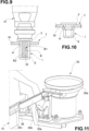
- an automatic insert application system is configured to place a threaded insert I (shown in Fig. 9 and 10 ) into a corresponding hole or housing H preliminarily formed in a wall w of the tube or profiled section T by laser machining.
- the automatic insert application system 30 is integrated into the machine and is configured to operate in coordination with the working head 12.
- Inserts applicable with the machine according to the invention are, for example, standard inserts comprising a bushing body having an outer surface S with a polygonal cross section, in particular hexagonal, and a flange or head F formed at a proximal end of the bushing body.
- a threaded hole B is formed in the bushing body, which comprises a proximal segment B1 having a larger diameter and arranged at the head F, and a distal segment B2 having a smaller diameter and provided with a threading.
- Examples of standard inserts applicable with the machine according to the invention are open hexagonal inserts M4, M5, M6, M8 with cylindrical head, closed hexagonal inserts M4, M5, M6, M8 with cylindrical head, open hexagonal inserts M4, M5, M6, M8 with reduced head and closed hexagonal inserts M4, M5, M6, M8 with reduced head.
- Fig. 9 and 10 show an open hexagonal insert with a cylindrical head.
- the automatic insert application system 30 comprises a riveter 31 of a type known per se, said riveter provided with a threaded rotating pin 32 configured to engage the threaded hole B of the threaded insert I for gripping and placing the threaded insert I.
- the riveter 31 comprises, in a manner known per se, a motor or actuator 31a to drive the rotation of the threaded pin 32.
- the placement of the threaded insert I takes place by forcefully inserting, by means of the riveter 31, the threaded insert I into the housing H until the head F comes into contact with the wall w of the tube or profiled section T; subsequently, the riveter 31 is slightly extracted causing the deformation of a part of the insert comprised between the distal threaded segment B2 and the wall w of the tube or profiled section T and which has a reduced thickness due to the presence of the hole segment B1 of larger diameter (see Fig. 10 ); in this way the wall w of the tube or profiled section T is clamped between the head F and the deformed part of the threaded insert. Lastly, the riveter 31 is removed by unscrewing the threaded pin 32 from the threaded insert I so anchored.
- the riveter 31 is mounted on a support structure 33, which in turn is attached to the carriage 28.
- the riveter 31 thus moves together with the carriage 28, and thus also together with the working head 12.
- the riveter 31 is thus translationally integral with the working head 12 both in the transverse direction y and in the vertical direction z.
- the position of the riveter 31 will be precisely on the same plane yz (orthogonal to the axis x of the tube or profiled section) of the working head 12; in this way, after having cut the hole in the tube or profiled section T with the working head 12, by moving only the y and z axes it is possible to bring the riveter 31 to insert the insert I in the same hole without needing to move the tube or the profiled section T being worked and/or to move the riveter 31 with further controlled axes.
- a linear actuator 34 is interposed between the support structure 33 and the riveter 31, which is configured to move the riveter 31 relative to the carriage 28 and thus the working head 12 along a direction parallel to the z axis.
- the riveter 31 is movable between a rest position corresponding to an upper end position of the linear actuator 34 (shown in Fig. 1 and 2 ), and a working position corresponding to a lower end position of the linear actuator 34 (shown in Fig. 7 ).
- the stroke of the riveter 31 is represented by the arrow z2 in Fig. 2 to 8 .
- the insert picking seat 36 is configured to receive only one threaded insert I at a time and is also shaped to prevent the threaded insert received therein from rotating about its central axis.
- the picking carriage 35c is movable from the retracted position shown in Fig. 11 and 12 to a forward position shown in Fig. 2 to 8 ; an actuator 35d is intended for this movement.
- the picking carriage 35c in its forward position allows the metal insert I to be picked up by the riveter 31, in the manner that will be described below.
- a guide (not shown) is provided, arranged alongside the picking carriage 35c. The above configuration allows the insert picking seat 36 to receive inserts I individually, such that they may be processed by the riveter 31.
- the insert supply assembly 35 and the insert picking seat 36 are arranged next to the carriage 28 and thus the riveter 31.
- the carriage 28 is therefore configured to shuttle between the tube or profiled section T and the insert picking seat 36 to allow the riveter 31 to grip the threaded insert I from the insert picking seat 36 and allow the riveter 31 to place the threaded insert on the tube or profiled section T, between a hole cutting operation and a subsequent cutting operation carried out on the tube or profiled section T by the working head 12.
- hole cutting operation means an operation in which the hole or housing H is formed in the wall w of the tube or profiled section T.
- “Cutting operation” means more generally any laser cutting operation performed on the tube or profiled section T, including the aforesaid hole cutting.
- a presence sensor 35e such as a photocell, is also arranged configured to detect the presence of the threaded insert I in the insert picking seat 36 when the picking carriage 35c is found in its forward position.
- the position of the insert picking seat 36 with the picking carriage 35 in the forward position is shown with a dashed line in Fig. 12 .
- Fig. 2 shows a hole cutting step by means of laser cutting of the tube or profiled section T.
- a housing H is formed in the tube or profiled section T by means of the working head 12.
- the riveter 31 in the resting position remains out of the way, allowing the machine to work without limitations.
- Fig. 3 shows a preparation step for picking the insert I.
- the carriage 28 is moved from the tube or profiled section T to the insert picking seat 26.
- the riveter 31 is positioned vertically on the axis of the insert I, which is located in the insert picking seat 36 with the carriage 35c in the forward position.
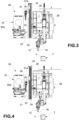
- Fig. 4 shows a lowering step of the riveter 31 in the picking position.
- Fig. 5 shows an insert picking step.
- Fig. 6 shows a riveter exiting step with insert.
- the riveter 31 extracts the insert I from the insert picking seat 36 and is ready for the application step in the previously made hole or housing H.
- Fig. 7 shows an insert application step on the tube or profiled section being worked.
- the riveter 31 applies the insert I into the previously formed hole or housing H. Note that the riveter 31 is further moved to its lower end position or working position.
- the riveter 31 operates in the manner described above with reference to Fig. 9 and 10 .
- a step of returning to the cutting position is shown in Fig. 8 .
- the riveter 31 By raising the riveter 31 by means of the linear actuator 34 and appropriately moving the y and z axes of the carriage 28, it returns to the laser cutting step by means of the working head 12.
- the automatic controls of the machine described above comprise a procedure for checking the insert type and the proper picking of the insert from the insert picking seat.
- the presence sensor 35e is configured to change state due to the picking of the threaded insert I from the insert picking seat 36 and consequently provide a detection signal.
- the presence sensor 35e is a photocell operating on the insert I by reflection
- the presence sensor 35e may be in an energized state
- the presence sensor 35e may be in a de-energized state.
- the presence sensor 35e will de-energize at a precise height z depending on the type of insert being processed (expected picking height).
- expected picking height the height reached by the riveter 31 when the change in state of the presence sensor 35e is detected. If the detected picking height corresponds to the expected one, the subsequent steps taken are moving the carriage 28 and the riveter 31 for the application of the insert I on the tube or profiled section T. If, on the other hand, the detected picking height does not correspond to the expected picking height, it means that:
- the riveter 31 positions itself near the picking point where a small pneumatic clamp (not shown) is provided that grips the insert to be discarded and holds it so that the riveter 31 may be unscrewed therefrom; subsequently the clamp opens and the defective insert falls into a shaft intended for cutting waste (not shown) and the riveter 31 starts up again for a new picking.
- a small pneumatic clamp (not shown) is provided that grips the insert to be discarded and holds it so that the riveter 31 may be unscrewed therefrom; subsequently the clamp opens and the defective insert falls into a shaft intended for cutting waste (not shown) and the riveter 31 starts up again for a new picking.
- the automatic controls of the above-described machine further comprise a procedure for also checking the presence of the insert in the insert picking seat 36 with the picking carriage 35c in the forward position: it may occur, in fact, that, in the transition between the supply chute 35b and the selector carriage 35c, the insert does not descend and therefore the selector carriage 35c exits empty; in this case, the presence sensor 35e does not change state upon the arrival of the selector carriage 35c (because the insert is not present), and therefore orders a second picking attempt.
- Air blowers (not shown) arranged along the chute and blowing in the direction of descent may be provided to aid in the descent of the insert from the chute 35b.
- the automatic controls of the above-described machine further comprise a procedure for checking the correct insertion of the insert into the tube or profiled section.
- the machine introduces the insert I into the housing H, which has been previously cut by laser, it should find itself in the position shown in Fig. 7 .
- the automatic controls of the above-described machine further comprise a procedure for preparing the housing for the threaded insert by means of laser cutting.
- the application process of a threaded insert on a laser cutting system for tubes involves first removing the material from the tube or profiled section where the threaded insert is to be applied.
- Said area is defined as the housing of the threaded insert.
- the removal of the material to form the housing is carried out by laser machining.
- Such machining is referred to as preparatory laser geometry.
- Preparatory laser geometry involves cutting a polygonal geometry, in particular hexagonal, oriented in a manner consistent with the orientation assumed by the threaded insert during the selection and picking process. This orientation is preserved by the riveter 31 and is always the same to ensure proper insertion of the threaded insert into the housing.
- a threaded insert is described by means of a series of geometric parameters that also allow the machine to know the size and shape of the housing.
- the machine performs the preparatory geometry automatically, with the position reference determined by the placeholder. If needed, the user has the possibility to parametrically adjust the dimensions and apply particular laser cutting parameters.
Landscapes
- Engineering & Computer Science (AREA)
- Physics & Mathematics (AREA)
- Optics & Photonics (AREA)
- Mechanical Engineering (AREA)
- Plasma & Fusion (AREA)
- General Engineering & Computer Science (AREA)
- Laser Beam Processing (AREA)
- Automatic Assembly (AREA)
Claims (6)
- Methode zum Betrieb einer Maschine zum Laserschneiden von Rohren und profilierten Abschnitten, umfassendeinen Arbeitskopf (12) mit einer Bündelungsvorrichtung (18), die angepasst ist, einen gebündelten Laserstrahl auf eine Oberfläche eines zu bearbeitenden Rohrs oder profilierten Abschnitts (T) zu emittieren, undeinen Schlitten (28), auf dem der Arbeitskopf (12) eingebaut ist, wobei der Schlitten (28) eingebaut wird, so dass er sich in Bezug auf den zu bearbeitenden Rohr oder profilierten Abschnitt (T) sowohl in einer ersten Querrichtung (y) als auch in einer zweiten Querrichtung (z), die sich orthogonal zur ersten Querrichtung erstreckt, bewegen kann, wobei diese Querrichtungen orthogonal zu einer Längsachse des zu bearbeitenden Rohrs oder profilierten Abschnitts (T) sind, undein automatisches Einbringungssystem für Einsätze (30) zum Platzieren eines Gewindeeinsatzes (I) in eine Aufnahme, die in einer Wand (W) des Rohrs oder des profilierten Abschnitts (T) mittels des Laserstrahls erzeugt wird, wobei dieses automatische Einbringungssystem für Einsätze in die Maschine integriert ist und konfiguriert ist, in koordinierter Weise mit dem Arbeitskopf zu arbeiten,wobei das automatische Einbringungssystem für Einsätze (30) eine Nietmaschine (31) umfasst, die mit einem drehenden Gewindestift (32) versehen ist, der konfiguriert ist, in ein Gewindeloch (B) des Gewindeeinsatzes (I) zum Greifen und Platzieren des Gewindeeinsatzes (I) einzudringen,wobei der Arbeitskopf (12) und die Nietmaschine (31) auf dem Schlitten (28) eingebaut sind, so dass sie sich einstückig mit dem Schlitten sowohl in der ersten Querrichtung (y) als auch in der zweiten Querrichtung (z) verschieben ,wobei das automatische Einbringungssystem für Einsätze (30) ferner eine Einsatzabgabe-Baugruppe (35) und einen Einsatzsammelsitz (36) umfasst, der konfiguriert ist, Einsätze einzeln von der Einsatzabgabe-Baugruppe zu empfangen, wobei die Einsatzabgabe-Baugruppe und der Einsatzsammelsitz benachbart dem Schlitten (28) angeordnet sind,wobei das automatische Einbringungssystem für Einsätze (30) ferner einen Näherungssensor (35e) umfasst, der konfiguriert ist, das Vorhandensein des Gewindeeinsatzes (I) in dem Einsatzsammelsitz (36) zu erfassen,und wobei die Methode die folgenden Schritte umfasst:a) Erzeugen einer Aufnahme (H) in dem Rohr oder in dem profilierten Abschnitt (T) mittels des Arbeitskopfs (12),b) Bewegen des Schlittens (28) von dem Rohr oder dem profilierten Abschnitt (T) zu dem Einsatzsammelsitz (36),c) Greifen eines Gewindeeinsatzes (I) aus dem Einsatzsammelsitz (36) mittels der Nietmaschine (31),d) Bewegen des Schlittens (28) von dem Einsatzsammelsitz (36) zu dem Rohr oder dem profilierten Abschnitt (T),e) Platzieren des Gewindeeinsatzes (I) in die Aufnahme (H) des Rohrs oder des profilierten Abschnitts (T) mittels der Nietmaschine (31), undf) Durchführen eines Schneidschritt mittels des Arbeitskopfs (12),wobei der Näherungssensor (35e) konfiguriert ist, seinen Zustand zu ändern, wenn der Gewindeeinsatz (I) aus dem Einsatzsammelsitz (36) entnommen wird, und dadurch ein Erfassungssignal zu liefern und wobei der Schritt c) die folgenden Schritte umfasst:c1) Greifen des Gewindeeinsatzes (I) mittels der Nietmaschine (31) und Anheben des Gewindeeinsatzes (I) aus dem Einsatzsammelsitz (36),c2) Bestimmen, basierend auf dem Erfassungssignal, einer erfassten Entnahmehöhe, die durch den Gewindeeinsatz (I) während des Entnehmens erreicht wird, bei der der Näherungssensor (35e) seinen Zustand geändert hat,c3) Vergleichen der erfassten Entnahmehöhe mit einer erwarteten Entnahmehöhe, die von den geometrischen Parametern des Gewindeeinsatzes (I) abhängt,c4) Wenn die erfasste Entnahmehöhe von der erwarteten Entnahmehöhe abweicht, neu Positionieren des Gewindeeinsatzes (I) in den Einsatzsammelsitz (36), Loslassen des Gewindeeinsatzes (I) und Wiederholen der Schritte c1)-c3),c5) Wenn die erfasste Entnahmehöhe noch von der erwarteten Entnahmehöhe abweicht, Weglassen des Gewindeeinsatzes (I).
- Methode nach Anspruch 1, wobei das automatische Einbringungssystem für Einsätze (30) ferner einen Linearantrieb (34) umfasst, der auf dem Schlitten eingebaut ist und auf dem die Nietmaschine (31) eingebaut ist, wobei dieser Linearantrieb konfiguriert ist, die Nietmaschine (31) in Bezug auf den Schlitten in der zweiten Querrichtung zwischen einer Ruheposition und einer Arbeitsposition zu verschieben.
- Methode nach Anspruch 1 oder 2, wobei der Schlitten konfiguriert ist, zwischen dem Rohr oder dem profilierten Abschnitt (T) und dem Einsatzsammelsitz (36) hin- und her zu bewegen, um der Nietmaschine (31) zu ermöglichen (31) den Gewindeeinsatz (I) aus dem Einsatzsammelsitz (36) zu greifen und den Gewindeeinsatz (I) auf dem Rohr oder dem profilierten Abschnitt (T) zu platzieren, zwischen einem Lochschneidschritt und einem folgenden Schneidschritt, der auf dem Rohr oder dem profilierten Abschnitt (T) mittels des Arbeitskopfs durchgeführt wird.
- Methode nach einem der vorhergehenden Ansprüche, wobei der Näherungssensor (35e) ferner konfiguriert ist, seinen Zustand zu ändern, weil der Gewindeeinsatz (I), der von der Einsatzzuführeinheit (35) abgegeben wird, in den Einsatzsammelsitz (36) aufgenommen wird, und dadurch ein Erfassungssignal zu liefern, und wobei der Schritt c) das Wiederholen der Abgabe des Gewindeeinsatzes (I) durch die Einsatzabgabe-Baugruppe (35) umfasst, wenn der Gewindeeinsatz (I) in dem Einsatzsammelsitz (36) nicht aufgenommen wird.
- Methode nach einem der vorhergehenden Ansprüche, wobei der Schritt e) die folgenden Schritte umfasst:e1) Absenken der Nietmaschine (31) mit dem Gewindeeinsatz (I) bis die Aufnahme (H) des Rohrs oder des profilierten Abschnitts (T) belegt wird,e2) Bestimmen einer erfassten Arbeitshöhe, die durch die Nietmaschine (31) erreicht wird,e3) Vergleichen der erfassten Arbeitshöhe mit einer erwarteten Arbeitshöhe, die von den Abmessungen des Rohrs oder des profilierten Abschnitts (T) abhängt,e4) Wenn die erfassten Arbeitshöhe von der erwarteten Arbeitshöhe abweicht, Weglassen des Gewindeeinsatzes (I).
- Methode nach einem der vorhergehenden Ansprüche, wobei der Schritt a) basierend auf den Eingabedaten durchgeführt wird, die eine vorgegebene Position eines Schwerpunkts der Aufnahme (H) in dem Rohr oder dem profilierten Abschnitt (T) und geometrische Parameter des einzubringenden Gewindeeinsatzes (I) umfassen.
Applications Claiming Priority (2)
| Application Number | Priority Date | Filing Date | Title |
|---|---|---|---|
| IT102021000003977A IT202100003977A1 (it) | 2021-02-22 | 2021-02-22 | Macchina per la lavorazione laser di tubi e profili con sistema automatico per l’applicazione di inserti filettati integrato nella macchina |
| PCT/IB2022/051404 WO2022175855A1 (en) | 2021-02-22 | 2022-02-17 | Method for operating a machine for laser machining of tubes and profiled sections with an automatic system for the application of threaded inserts integrated in the machine |
Publications (2)
| Publication Number | Publication Date |
|---|---|
| EP4294594A1 EP4294594A1 (de) | 2023-12-27 |
| EP4294594B1 true EP4294594B1 (de) | 2025-04-23 |
Family
ID=75769849
Family Applications (1)
| Application Number | Title | Priority Date | Filing Date |
|---|---|---|---|
| EP22706122.3A Active EP4294594B1 (de) | 2021-02-22 | 2022-02-17 | Methode zum betrieb einer laserbearbeitungsmaschine von rohren oder profilen mit einem in der maschine integrierten system zur automatisierten einbringung von gewindeeinsätzen |
Country Status (10)
| Country | Link |
|---|---|
| US (1) | US20240116138A1 (de) |
| EP (1) | EP4294594B1 (de) |
| JP (1) | JP7833475B2 (de) |
| KR (1) | KR20230145579A (de) |
| CN (1) | CN116981535B (de) |
| ES (1) | ES3035652T3 (de) |
| IT (1) | IT202100003977A1 (de) |
| PL (1) | PL4294594T3 (de) |
| TW (1) | TWI906478B (de) |
| WO (1) | WO2022175855A1 (de) |
Families Citing this family (1)
| Publication number | Priority date | Publication date | Assignee | Title |
|---|---|---|---|---|
| CN120715649B (zh) * | 2025-07-30 | 2025-11-21 | 小洋电源股份有限公司 | 一种铅酸电池正负极衬套一体化复合加工系统 |
Family Cites Families (17)
| Publication number | Priority date | Publication date | Assignee | Title |
|---|---|---|---|---|
| FR2313998A1 (fr) * | 1975-06-12 | 1977-01-07 | Otalu Sa | Appareil pour la pose automatique de rivets tubulaires taraudes |
| JPS5834267B2 (ja) * | 1980-10-13 | 1983-07-26 | 株式会社 岡部機械製作所 | インサ−トナツトの捻込機 |
| JP3104216B2 (ja) * | 1993-12-15 | 2000-10-30 | トヨタ車体株式会社 | 複合式溶接治具とこれを用いた溶接方法 |
| DE102004006407A1 (de) * | 2004-02-10 | 2005-09-01 | Daimlerchrysler Ag | Vorrichtung zum automatisierten Setzen eines Blindniets |
| DE102004054582A1 (de) * | 2004-11-11 | 2006-05-24 | Siemens Ag | Verfahren zum Verbinden von Bauteilen durch Nieten oder Schrauben und Laserschweißen |
| JP4803483B2 (ja) | 2005-06-27 | 2011-10-26 | 株式会社ニイガタマシンテクノ | インサートナットの螺入方法及びインサートナット螺入装置 |
| JP4851952B2 (ja) | 2007-02-06 | 2012-01-11 | Juki株式会社 | 表面実装装置 |
| US7603785B2 (en) * | 2007-02-20 | 2009-10-20 | Electro Scientific Industries, Inc. | Air bearing assembly for guiding motion of optical components of a laser processing system |
| CN201603997U (zh) * | 2009-12-11 | 2010-10-13 | 哈尔滨量具刃具集团有限责任公司 | 新型钻压铆机床 |
| JP5643082B2 (ja) | 2010-12-28 | 2014-12-17 | 川崎重工業株式会社 | 作業の良否判定システム及び良否判定方法 |
| EP2548691B1 (de) * | 2011-07-22 | 2016-08-31 | TRUMPF Werkzeugmaschinen GmbH + Co. KG | Entladevorrichtung für eine Bearbeitungsvorrichtung zur Bearbeitung von Rohren mit einer in Höhenrichtung beweglichen Ablagefläche ; Verfahren zur schneidenden Bearbeitung eines Rohres mit einer solchen Vorrichtung |
| EP2767363A4 (de) * | 2011-10-14 | 2015-12-16 | Amada Co Ltd | Laser/stanzbearbeitungsverfahren, laser/stanzbearbeitungsmaschine und haftwerkzeug |
| DE102016106067A1 (de) | 2016-04-04 | 2017-10-05 | Trumpf Werkzeugmaschinen Gmbh + Co. Kg | Verfahren und Bearbeitungsmaschine zum schneidenden Bearbeiten von plattenförmigen oder stabförmigen Werkstücken |
| EP3529675B1 (de) * | 2016-10-21 | 2022-12-14 | Trumpf Werkzeugmaschinen GmbH + Co. KG | Innenraum-personenortung-basierte fertigungssteuerung in der metallverarbeitenden industrie |
| DE102018122717A1 (de) * | 2018-09-17 | 2020-03-19 | Trumpf Werkzeugmaschinen Gmbh + Co. Kg | Verfahren zur schneidenden Bearbeitung von Rohren in einer Laserrohrschneidmaschine sowie Laserrohrschneidmaschine |
| CN111054875B (zh) * | 2020-01-03 | 2024-10-15 | 博众精工科技股份有限公司 | 基于视觉检测的铆接装置 |
| CN111842769A (zh) * | 2020-07-24 | 2020-10-30 | 东莞市诚大机械科技有限公司 | 一种垫圈震动送料装置及应用其的铆接机 |
-
2021
- 2021-02-22 IT IT102021000003977A patent/IT202100003977A1/it unknown
-
2022
- 2022-02-17 US US18/276,472 patent/US20240116138A1/en active Pending
- 2022-02-17 CN CN202280016102.5A patent/CN116981535B/zh active Active
- 2022-02-17 ES ES22706122T patent/ES3035652T3/es active Active
- 2022-02-17 JP JP2023550241A patent/JP7833475B2/ja active Active
- 2022-02-17 EP EP22706122.3A patent/EP4294594B1/de active Active
- 2022-02-17 WO PCT/IB2022/051404 patent/WO2022175855A1/en not_active Ceased
- 2022-02-17 KR KR1020237030288A patent/KR20230145579A/ko active Pending
- 2022-02-17 PL PL22706122.3T patent/PL4294594T3/pl unknown
- 2022-02-21 TW TW111106190A patent/TWI906478B/zh active
Also Published As
| Publication number | Publication date |
|---|---|
| KR20230145579A (ko) | 2023-10-17 |
| CN116981535A (zh) | 2023-10-31 |
| JP7833475B2 (ja) | 2026-03-19 |
| ES3035652T3 (en) | 2025-09-05 |
| PL4294594T3 (pl) | 2025-06-23 |
| EP4294594A1 (de) | 2023-12-27 |
| CN116981535B (zh) | 2026-04-17 |
| IT202100003977A1 (it) | 2022-08-22 |
| US20240116138A1 (en) | 2024-04-11 |
| JP2024507234A (ja) | 2024-02-16 |
| TW202239505A (zh) | 2022-10-16 |
| WO2022175855A1 (en) | 2022-08-25 |
| TWI906478B (zh) | 2025-12-01 |
Similar Documents
| Publication | Publication Date | Title |
|---|---|---|
| CN109070275B (zh) | 用于切割加工板状或棒状工件的方法及加工机器 | |
| US5361484A (en) | Method of guiding a rivet around a curve | |
| US5531009A (en) | Apparatus for removing an undeformed rivet from a hole | |
| US6290439B1 (en) | Method and apparatus for forming parts from a continuous stock material and associated forge | |
| US5407003A (en) | Apparatus for cooling a coil | |
| US5203855A (en) | Method of mist lubrication, chip vacuum and coil cooling | |
| EP0399798A2 (de) | Vorrichtung zum Montieren von Befestigungselementen | |
| JP2018134690A (ja) | 複合歯切加工装置 | |
| EP2893987B1 (de) | Bearbeitungsvorrichtung und verfahren zum bewegen eines werkzeuges bei einer bearbeitungsvorrichtung | |
| US20240116138A1 (en) | Method for operating a machine for laser machining of tubes and profiled sections with an automatic system for the application of threaded inserts integrated in the machine | |
| US11478835B2 (en) | Machining planar workpieces | |
| US5347896A (en) | Automated collet loading for the manufacture of contact lenses | |
| US20190217360A1 (en) | Tools, machines, and methods for processing planar workpieces | |
| EP4543650B1 (de) | Automatische schneidemaschine für flachstücke und zugehöriges verfahren | |
| EP0652060A1 (de) | Verfahren und Vorrichtung zur Formung von rechteckigen gekrümmten Nadeln | |
| EP0650785B1 (de) | Positionier- und Pressvorrichtung für gekrümmte chirurgische Nadeln | |
| US20240316696A1 (en) | Automated slug removing method and device | |
| EP4219089A1 (de) | Stanzzelle zum stanzen von werkstücken | |
| CN218193855U (zh) | 一种数控机床的夹具对准装置 | |
| CN121551649A (zh) | 具有多工位加工系统的车珠机及加工方法 | |
| KR910003734B1 (ko) | 자동 태핑 장치 및 자동 태핑 방법 | |
| CN121624908A (zh) | 用于连串珠胚的上料机构、车珠机及加工方法 | |
| Endres | Dual Lower Ram Riveting Machine | |
| JP2000326041A (ja) | 加締め加工機 | |
| JPWO2001026441A1 (ja) | 部品組付装置 |
Legal Events
| Date | Code | Title | Description |
|---|---|---|---|
| STAA | Information on the status of an ep patent application or granted ep patent |
Free format text: STATUS: UNKNOWN |
|
| STAA | Information on the status of an ep patent application or granted ep patent |
Free format text: STATUS: THE INTERNATIONAL PUBLICATION HAS BEEN MADE |
|
| PUAI | Public reference made under article 153(3) epc to a published international application that has entered the european phase |
Free format text: ORIGINAL CODE: 0009012 |
|
| STAA | Information on the status of an ep patent application or granted ep patent |
Free format text: STATUS: REQUEST FOR EXAMINATION WAS MADE |
|
| 17P | Request for examination filed |
Effective date: 20230920 |
|
| AK | Designated contracting states |
Kind code of ref document: A1 Designated state(s): AL AT BE BG CH CY CZ DE DK EE ES FI FR GB GR HR HU IE IS IT LI LT LU LV MC MK MT NL NO PL PT RO RS SE SI SK SM TR |
|
| DAV | Request for validation of the european patent (deleted) | ||
| DAX | Request for extension of the european patent (deleted) | ||
| REG | Reference to a national code |
Ref country code: DE Free format text: PREVIOUS MAIN CLASS: B23K0026000000 Ipc: B21J0015140000 Ref country code: DE Ref legal event code: R079 Ref document number: 602022013530 Country of ref document: DE Free format text: PREVIOUS MAIN CLASS: B23K0026000000 Ipc: B21J0015140000 |
|
| GRAP | Despatch of communication of intention to grant a patent |
Free format text: ORIGINAL CODE: EPIDOSNIGR1 |
|
| STAA | Information on the status of an ep patent application or granted ep patent |
Free format text: STATUS: GRANT OF PATENT IS INTENDED |
|
| RIC1 | Information provided on ipc code assigned before grant |
Ipc: B25B 27/00 20060101ALI20241002BHEP Ipc: B23K 101/28 20060101ALI20241002BHEP Ipc: B23K 101/06 20060101ALI20241002BHEP Ipc: B23K 26/382 20140101ALI20241002BHEP Ipc: B23K 26/38 20140101ALI20241002BHEP Ipc: B23K 26/08 20140101ALI20241002BHEP Ipc: B23K 26/00 20140101ALI20241002BHEP Ipc: F16B 37/06 20060101ALI20241002BHEP Ipc: B23P 23/04 20060101ALI20241002BHEP Ipc: B21J 15/32 20060101ALI20241002BHEP Ipc: B21J 15/14 20060101AFI20241002BHEP |
|
| INTG | Intention to grant announced |
Effective date: 20241031 |
|
| GRAS | Grant fee paid |
Free format text: ORIGINAL CODE: EPIDOSNIGR3 |
|
| GRAJ | Information related to disapproval of communication of intention to grant by the applicant or resumption of examination proceedings by the epo deleted |
Free format text: ORIGINAL CODE: EPIDOSDIGR1 |
|
| GRAL | Information related to payment of fee for publishing/printing deleted |
Free format text: ORIGINAL CODE: EPIDOSDIGR3 |
|
| STAA | Information on the status of an ep patent application or granted ep patent |
Free format text: STATUS: REQUEST FOR EXAMINATION WAS MADE |
|
| P01 | Opt-out of the competence of the unified patent court (upc) registered |
Free format text: CASE NUMBER: APP_4543/2025 Effective date: 20250128 |
|
| STAA | Information on the status of an ep patent application or granted ep patent |
Free format text: STATUS: GRANT OF PATENT IS INTENDED |
|
| GRAA | (expected) grant |
Free format text: ORIGINAL CODE: 0009210 |
|
| STAA | Information on the status of an ep patent application or granted ep patent |
Free format text: STATUS: THE PATENT HAS BEEN GRANTED |
|
| INTC | Intention to grant announced (deleted) | ||
| AK | Designated contracting states |
Kind code of ref document: B1 Designated state(s): AL AT BE BG CH CY CZ DE DK EE ES FI FR GB GR HR HU IE IS IT LI LT LU LV MC MK MT NL NO PL PT RO RS SE SI SK SM TR |
|
| REG | Reference to a national code |
Ref country code: GB Ref legal event code: FG4D |
|
| REG | Reference to a national code |
Ref country code: CH Ref legal event code: EP |
|
| REG | Reference to a national code |
Ref country code: DE Ref legal event code: R096 Ref document number: 602022013530 Country of ref document: DE |
|
| REG | Reference to a national code |
Ref country code: IE Ref legal event code: FG4D |
|
| REG | Reference to a national code |
Ref country code: NL Ref legal event code: MP Effective date: 20250423 |
|
| REG | Reference to a national code |
Ref country code: ES Ref legal event code: FG2A Ref document number: 3035652 Country of ref document: ES Kind code of ref document: T3 Effective date: 20250905 |
|
| PG25 | Lapsed in a contracting state [announced via postgrant information from national office to epo] |
Ref country code: NL Free format text: LAPSE BECAUSE OF FAILURE TO SUBMIT A TRANSLATION OF THE DESCRIPTION OR TO PAY THE FEE WITHIN THE PRESCRIBED TIME-LIMIT Effective date: 20250423 |
|
| REG | Reference to a national code |
Ref country code: AT Ref legal event code: MK05 Ref document number: 1787324 Country of ref document: AT Kind code of ref document: T Effective date: 20250423 |
|
| PG25 | Lapsed in a contracting state [announced via postgrant information from national office to epo] |
Ref country code: FI Free format text: LAPSE BECAUSE OF FAILURE TO SUBMIT A TRANSLATION OF THE DESCRIPTION OR TO PAY THE FEE WITHIN THE PRESCRIBED TIME-LIMIT Effective date: 20250423 Ref country code: PT Free format text: LAPSE BECAUSE OF FAILURE TO SUBMIT A TRANSLATION OF THE DESCRIPTION OR TO PAY THE FEE WITHIN THE PRESCRIBED TIME-LIMIT Effective date: 20250825 |
|
| REG | Reference to a national code |
Ref country code: LT Ref legal event code: MG9D |
|
| PG25 | Lapsed in a contracting state [announced via postgrant information from national office to epo] |
Ref country code: GR Free format text: LAPSE BECAUSE OF FAILURE TO SUBMIT A TRANSLATION OF THE DESCRIPTION OR TO PAY THE FEE WITHIN THE PRESCRIBED TIME-LIMIT Effective date: 20250724 Ref country code: NO Free format text: LAPSE BECAUSE OF FAILURE TO SUBMIT A TRANSLATION OF THE DESCRIPTION OR TO PAY THE FEE WITHIN THE PRESCRIBED TIME-LIMIT Effective date: 20250723 |
|
| PG25 | Lapsed in a contracting state [announced via postgrant information from national office to epo] |
Ref country code: BG Free format text: LAPSE BECAUSE OF FAILURE TO SUBMIT A TRANSLATION OF THE DESCRIPTION OR TO PAY THE FEE WITHIN THE PRESCRIBED TIME-LIMIT Effective date: 20250423 |
|
| PG25 | Lapsed in a contracting state [announced via postgrant information from national office to epo] |
Ref country code: HR Free format text: LAPSE BECAUSE OF FAILURE TO SUBMIT A TRANSLATION OF THE DESCRIPTION OR TO PAY THE FEE WITHIN THE PRESCRIBED TIME-LIMIT Effective date: 20250423 |
|
| PG25 | Lapsed in a contracting state [announced via postgrant information from national office to epo] |
Ref country code: AT Free format text: LAPSE BECAUSE OF FAILURE TO SUBMIT A TRANSLATION OF THE DESCRIPTION OR TO PAY THE FEE WITHIN THE PRESCRIBED TIME-LIMIT Effective date: 20250423 |
|
| PG25 | Lapsed in a contracting state [announced via postgrant information from national office to epo] |
Ref country code: RS Free format text: LAPSE BECAUSE OF FAILURE TO SUBMIT A TRANSLATION OF THE DESCRIPTION OR TO PAY THE FEE WITHIN THE PRESCRIBED TIME-LIMIT Effective date: 20250723 |
|
| PG25 | Lapsed in a contracting state [announced via postgrant information from national office to epo] |
Ref country code: IS Free format text: LAPSE BECAUSE OF FAILURE TO SUBMIT A TRANSLATION OF THE DESCRIPTION OR TO PAY THE FEE WITHIN THE PRESCRIBED TIME-LIMIT Effective date: 20250823 |
|
| PG25 | Lapsed in a contracting state [announced via postgrant information from national office to epo] |
Ref country code: LV Free format text: LAPSE BECAUSE OF FAILURE TO SUBMIT A TRANSLATION OF THE DESCRIPTION OR TO PAY THE FEE WITHIN THE PRESCRIBED TIME-LIMIT Effective date: 20250423 |
|
| PG25 | Lapsed in a contracting state [announced via postgrant information from national office to epo] |
Ref country code: DK Free format text: LAPSE BECAUSE OF FAILURE TO SUBMIT A TRANSLATION OF THE DESCRIPTION OR TO PAY THE FEE WITHIN THE PRESCRIBED TIME-LIMIT Effective date: 20250423 Ref country code: SM Free format text: LAPSE BECAUSE OF FAILURE TO SUBMIT A TRANSLATION OF THE DESCRIPTION OR TO PAY THE FEE WITHIN THE PRESCRIBED TIME-LIMIT Effective date: 20250423 |
|
| PG25 | Lapsed in a contracting state [announced via postgrant information from national office to epo] |
Ref country code: CZ Free format text: LAPSE BECAUSE OF FAILURE TO SUBMIT A TRANSLATION OF THE DESCRIPTION OR TO PAY THE FEE WITHIN THE PRESCRIBED TIME-LIMIT Effective date: 20250423 |
|
| PG25 | Lapsed in a contracting state [announced via postgrant information from national office to epo] |
Ref country code: EE Free format text: LAPSE BECAUSE OF FAILURE TO SUBMIT A TRANSLATION OF THE DESCRIPTION OR TO PAY THE FEE WITHIN THE PRESCRIBED TIME-LIMIT Effective date: 20250423 |
|
| REG | Reference to a national code |
Ref country code: DE Ref legal event code: R097 Ref document number: 602022013530 Country of ref document: DE |
|
| PG25 | Lapsed in a contracting state [announced via postgrant information from national office to epo] |
Ref country code: SK Free format text: LAPSE BECAUSE OF FAILURE TO SUBMIT A TRANSLATION OF THE DESCRIPTION OR TO PAY THE FEE WITHIN THE PRESCRIBED TIME-LIMIT Effective date: 20250423 |
|
| PLBE | No opposition filed within time limit |
Free format text: ORIGINAL CODE: 0009261 |
|
| STAA | Information on the status of an ep patent application or granted ep patent |
Free format text: STATUS: NO OPPOSITION FILED WITHIN TIME LIMIT |
|
| REG | Reference to a national code |
Ref country code: CH Ref legal event code: U11 Free format text: ST27 STATUS EVENT CODE: U-0-0-U10-U11 (AS PROVIDED BY THE NATIONAL OFFICE) Effective date: 20260301 |
|
| REG | Reference to a national code |
Ref country code: CH Ref legal event code: L10 Free format text: ST27 STATUS EVENT CODE: U-0-0-L10-L00 (AS PROVIDED BY THE NATIONAL OFFICE) Effective date: 20260304 |
|
| 26N | No opposition filed |
Effective date: 20260126 |
|
| PGFP | Annual fee paid to national office [announced via postgrant information from national office to epo] |
Ref country code: GB Payment date: 20260220 Year of fee payment: 5 |
|
| PGFP | Annual fee paid to national office [announced via postgrant information from national office to epo] |
Ref country code: ES Payment date: 20260302 Year of fee payment: 5 |
|
| PGFP | Annual fee paid to national office [announced via postgrant information from national office to epo] |
Ref country code: DE Payment date: 20260223 Year of fee payment: 5 |
|
| PGFP | Annual fee paid to national office [announced via postgrant information from national office to epo] |
Ref country code: IT Payment date: 20251205 Year of fee payment: 5 |
|
| PGFP | Annual fee paid to national office [announced via postgrant information from national office to epo] |
Ref country code: FR Payment date: 20260130 Year of fee payment: 5 |
|
| PGFP | Annual fee paid to national office [announced via postgrant information from national office to epo] |
Ref country code: TR Payment date: 20260216 Year of fee payment: 5 |
|
| PGFP | Annual fee paid to national office [announced via postgrant information from national office to epo] |
Ref country code: CH Payment date: 20260301 Year of fee payment: 5 |
|
| PGFP | Annual fee paid to national office [announced via postgrant information from national office to epo] |
Ref country code: PL Payment date: 20260204 Year of fee payment: 5 |