EP4292801B1 - Reifenform - Google Patents
Reifenform Download PDFInfo
- Publication number
- EP4292801B1 EP4292801B1 EP23199939.2A EP23199939A EP4292801B1 EP 4292801 B1 EP4292801 B1 EP 4292801B1 EP 23199939 A EP23199939 A EP 23199939A EP 4292801 B1 EP4292801 B1 EP 4292801B1
- Authority
- EP
- European Patent Office
- Prior art keywords
- laterally extending
- mold
- extending blades
- tire
- blades
- Prior art date
- Legal status (The legal status is an assumption and is not a legal conclusion. Google has not performed a legal analysis and makes no representation as to the accuracy of the status listed.)
- Active
Links
Images

Classifications
-
- B—PERFORMING OPERATIONS; TRANSPORTING
- B29—WORKING OF PLASTICS; WORKING OF SUBSTANCES IN A PLASTIC STATE IN GENERAL
- B29C—SHAPING OR JOINING OF PLASTICS; SHAPING OF MATERIAL IN A PLASTIC STATE, NOT OTHERWISE PROVIDED FOR; AFTER-TREATMENT OF THE SHAPED PRODUCTS, e.g. REPAIRING
- B29C33/00—Moulds or cores; Details thereof or accessories therefor
- B29C33/42—Moulds or cores; Details thereof or accessories therefor characterised by the shape of the moulding surface, e.g. ribs or grooves
-
- B—PERFORMING OPERATIONS; TRANSPORTING
- B29—WORKING OF PLASTICS; WORKING OF SUBSTANCES IN A PLASTIC STATE IN GENERAL
- B29D—PRODUCING PARTICULAR ARTICLES FROM PLASTICS OR FROM SUBSTANCES IN A PLASTIC STATE
- B29D30/00—Producing pneumatic or solid tyres or parts thereof
- B29D30/06—Pneumatic tyres or parts thereof (e.g. produced by casting, moulding, compression moulding, injection moulding, centrifugal casting)
- B29D30/0601—Vulcanising tyres; Vulcanising presses for tyres
- B29D30/0606—Vulcanising moulds not integral with vulcanising presses
-
- B—PERFORMING OPERATIONS; TRANSPORTING
- B33—ADDITIVE MANUFACTURING TECHNOLOGY
- B33Y—ADDITIVE MANUFACTURING, i.e. MANUFACTURING OF THREE-DIMENSIONAL [3-D] OBJECTS BY ADDITIVE DEPOSITION, ADDITIVE AGGLOMERATION OR ADDITIVE LAYERING, e.g. BY 3-D PRINTING, STEREOLITHOGRAPHY OR SELECTIVE LASER SINTERING
- B33Y80/00—Products made by additive manufacturing
-
- B—PERFORMING OPERATIONS; TRANSPORTING
- B60—VEHICLES IN GENERAL
- B60C—VEHICLE TYRES; TYRE INFLATION; TYRE CHANGING; CONNECTING VALVES TO INFLATABLE ELASTIC BODIES IN GENERAL; DEVICES OR ARRANGEMENTS RELATED TO TYRES
- B60C11/00—Tyre tread bands; Tread patterns; Anti-skid inserts
- B60C11/03—Tread patterns
- B60C11/12—Tread patterns characterised by the use of narrow slits or incisions, e.g. sipes
- B60C11/1236—Tread patterns characterised by the use of narrow slits or incisions, e.g. sipes with special arrangements in the tread pattern
- B60C11/124—Tread patterns characterised by the use of narrow slits or incisions, e.g. sipes with special arrangements in the tread pattern inclined with regard to a plane normal to the tread surface
-
- B—PERFORMING OPERATIONS; TRANSPORTING
- B29—WORKING OF PLASTICS; WORKING OF SUBSTANCES IN A PLASTIC STATE IN GENERAL
- B29D—PRODUCING PARTICULAR ARTICLES FROM PLASTICS OR FROM SUBSTANCES IN A PLASTIC STATE
- B29D30/00—Producing pneumatic or solid tyres or parts thereof
- B29D30/06—Pneumatic tyres or parts thereof (e.g. produced by casting, moulding, compression moulding, injection moulding, centrifugal casting)
- B29D30/0601—Vulcanising tyres; Vulcanising presses for tyres
- B29D30/0606—Vulcanising moulds not integral with vulcanising presses
- B29D2030/0607—Constructional features of the moulds
- B29D2030/0612—Means for forming recesses or protrusions in the tyres, e.g. grooves or ribs, to create the tread or sidewalls patterns
-
- B—PERFORMING OPERATIONS; TRANSPORTING
- B29—WORKING OF PLASTICS; WORKING OF SUBSTANCES IN A PLASTIC STATE IN GENERAL
- B29D—PRODUCING PARTICULAR ARTICLES FROM PLASTICS OR FROM SUBSTANCES IN A PLASTIC STATE
- B29D30/00—Producing pneumatic or solid tyres or parts thereof
- B29D30/06—Pneumatic tyres or parts thereof (e.g. produced by casting, moulding, compression moulding, injection moulding, centrifugal casting)
- B29D30/0601—Vulcanising tyres; Vulcanising presses for tyres
- B29D30/0606—Vulcanising moulds not integral with vulcanising presses
- B29D2030/0607—Constructional features of the moulds
- B29D2030/0613—Means, e.g. sipes or blade-like elements, for forming narrow recesses in the tyres, e.g. cuts or incisions for winter tyres
-
- B—PERFORMING OPERATIONS; TRANSPORTING
- B29—WORKING OF PLASTICS; WORKING OF SUBSTANCES IN A PLASTIC STATE IN GENERAL
- B29D—PRODUCING PARTICULAR ARTICLES FROM PLASTICS OR FROM SUBSTANCES IN A PLASTIC STATE
- B29D30/00—Producing pneumatic or solid tyres or parts thereof
- B29D30/06—Pneumatic tyres or parts thereof (e.g. produced by casting, moulding, compression moulding, injection moulding, centrifugal casting)
- B29D30/0601—Vulcanising tyres; Vulcanising presses for tyres
- B29D30/0606—Vulcanising moulds not integral with vulcanising presses
- B29D2030/0607—Constructional features of the moulds
- B29D2030/0616—Surface structure of the mould, e.g. roughness, arrangement of slits, grooves or channels
-
- B—PERFORMING OPERATIONS; TRANSPORTING
- B29—WORKING OF PLASTICS; WORKING OF SUBSTANCES IN A PLASTIC STATE IN GENERAL
- B29D—PRODUCING PARTICULAR ARTICLES FROM PLASTICS OR FROM SUBSTANCES IN A PLASTIC STATE
- B29D30/00—Producing pneumatic or solid tyres or parts thereof
- B29D30/06—Pneumatic tyres or parts thereof (e.g. produced by casting, moulding, compression moulding, injection moulding, centrifugal casting)
- B29D30/0601—Vulcanising tyres; Vulcanising presses for tyres
- B29D30/0606—Vulcanising moulds not integral with vulcanising presses
- B29D2030/0607—Constructional features of the moulds
- B29D2030/0617—Venting devices, e.g. vent plugs or inserts
-
- B—PERFORMING OPERATIONS; TRANSPORTING
- B29—WORKING OF PLASTICS; WORKING OF SUBSTANCES IN A PLASTIC STATE IN GENERAL
- B29D—PRODUCING PARTICULAR ARTICLES FROM PLASTICS OR FROM SUBSTANCES IN A PLASTIC STATE
- B29D30/00—Producing pneumatic or solid tyres or parts thereof
- B29D30/06—Pneumatic tyres or parts thereof (e.g. produced by casting, moulding, compression moulding, injection moulding, centrifugal casting)
- B29D30/0601—Vulcanising tyres; Vulcanising presses for tyres
- B29D30/0606—Vulcanising moulds not integral with vulcanising presses
- B29D30/0629—Vulcanising moulds not integral with vulcanising presses with radially movable sectors
- B29D2030/063—Vulcanising moulds not integral with vulcanising presses with radially movable sectors the moulds being split in upper and lower halves
-
- B—PERFORMING OPERATIONS; TRANSPORTING
- B29—WORKING OF PLASTICS; WORKING OF SUBSTANCES IN A PLASTIC STATE IN GENERAL
- B29D—PRODUCING PARTICULAR ARTICLES FROM PLASTICS OR FROM SUBSTANCES IN A PLASTIC STATE
- B29D30/00—Producing pneumatic or solid tyres or parts thereof
- B29D30/06—Pneumatic tyres or parts thereof (e.g. produced by casting, moulding, compression moulding, injection moulding, centrifugal casting)
- B29D30/0601—Vulcanising tyres; Vulcanising presses for tyres
- B29D30/0606—Vulcanising moulds not integral with vulcanising presses
- B29D30/0629—Vulcanising moulds not integral with vulcanising presses with radially movable sectors
Definitions
- This invention relates to a tire mold with a tire tread mold portion being divided into a plurality of mold segments.
- the subject invention also relates to a tire which is molded during its manufacturing process with said mold.
- a green tire is inserted into a tire mold where it is cured (vulcanized).
- the tire mold is designed to shape the tire and to mold the circumferential tread pattern into the tire.
- the mold also typically adds written information or branding on the sidewalls of the tire.
- the tire mold is closed by moving circumferential mold segments inward in a tire radial direction. Often each segment has on its inner face a plurality of blades extending into the mold, mostly in the radial direction, and forms a reverse imprint arranged to cut the surface of the green tire according to a desired tread pattern, wherein a blade arranged to protrude from the inner face of the mold segment is cutting a groove or a sipe within the tread of the tire. Then, the tire is subject to vulcanization. As a consequence, mold blades inserted into the green tire and subsequently removed from the cured tire, undergo forces caused by the movement of the rubber around them in both operations.
- the forces exerted by the rubber on the blades can be more or less strong.
- strong forces may cause the breakage of the blades during demolding.
- the blades such as the lateral blades and the circumferential blades, are arranged to project in a direction toward a center of the mold segment, i.e. in the radial direction that corresponds to a direction essentially perpendicular to the inner face of the mold segment.
- the mold segments are moved in a radial direction that passes through the circumferential center of the mold segment defining also the operating direction.
- Blades that are positioned centrally with regard to the circumferential direction in the mold segment will project in the operating direction of said segment, but blades positioned at the transverse edges of the mold segment project in a direction forming an angle with the operating direction of the mold segment when extending radially.
- the rubber will generate forces on the surface of the blades to a greater or lesser extent depending on the relative inclination of the blades to the operating direction.
- forces applied on the blades become too large, the blades may break. There is a need to improve the situation.
- Modern tires comprise complex tread patterns that need to be continuous around the circumference of the tire to improve the tire performances.
- US 2009/035404 discloses a tire mold with a plurality of radial mold segments with blades arranged in each of the mold segments.
- the blades positioned at circumferential ends (i.e. the transverse edges) of each segment are inclined outward to the radial direction of the mold segment.
- the blades can be all parallel and oriented in the movement direction of the mold segment.
- the risks of damage to the blades are reduced. Nevertheless, this implies leaving a gap between the blades and the mold segment edge or having sipes with smaller height in the vicinity of the edges to allow two mold segments to be moved into contact with one another. This is likely to form a gap in the tread pattern, so that there is a need to improve such a design.
- difficulties are encountered to close the tire mold without damaging the blades at the mold segment edge by collision with blades of the neighboring segment.
- US 2006/008547 discloses a tire mold with a plurality of radial mold segments.
- Each mold segment comprises a plurality of pieces partitioned in a tire circumferential direction.
- the pieces comprise projecting stacks for forming grooves on a tread surface.
- the pieces are slidable relative to each other in a circumferential direction except the piece that is disposed at the central portion of each mold segment.
- the pieces that are closer to the edge of a mold segment move and rotate toward a non-radial direction parallel to the direction of movement of the mold segment.
- the use of movable parts comprising blades that are used to shape the tread pattern involves a great complexity and has limited cost efficiency.
- WO2007/017991 A1 describes a tire mold in accordance with the preamble of claim 1.
- a tire mold comprising a tread mold portion which is divided in a tire circumferential direction into a plurality of mold segments, each mold segment having transverse edges (in particular two or at least two transverse edges) and being movable in a respective operation direction between i) an opened position, in which the mold segments are spaced from each other (or away from each other), and ii) a closed position, in which two neighboring mold segments are in contact with each other by one of their transverse edges, each of the mold segments comprising a plurality of blades for molding laterally extending sipes on a tire tread surface.
- At least a first one of said mold segments has laterally extending blades located at a first transverse edge
- at least a second one of said mold segments (a second mold segment) neighboring said first one of said mold segments has laterally extending blades located at a second transverse edge adjacent to the first transverse edge of the first one of said mold segments
- said laterally extending blades located at the first transverse edge of the first one of said mold segments interlock between (or interlock with, or in other words, mesh or engage with) the laterally extending blades located at the second transverse edge of the second one of said mold segments when the mold segments are in the closed position.
- a tire mold comprises a tread mold portion which is divided in a tire circumferential direction into a plurality of mold segments each having an inner face (or a radially inner face) curved along the circumferential direction according to an arc (or circular segment) defined by an angle (or center angle) ⁇ , each mold segment having transverse edges (in particular two or at least two transverse edges) and being movable in a respective operation direction between (i) an opened position, in which the mold segments are spaced from each other and (ii) a closed position in which two neighboring mold segments are in contact with each other by one of their transverse edges, each of the mold segments comprising a plurality of laterally extending blades (or in other words lateral blades) forming projections from the inner face of the mold segment for molding laterally extending sipes on a tire tread surface.
- the mold segments have according to their length (in a circumferential direction) a first end portion, a second end portion and a central portion arranged between the first and the second end portions, wherein laterally extending blades of the central portion are extending in the operating direction, and wherein laterally extending blades of one or more of the first end portion and the second end portion are inclined blades that extend in a direction forming an angle ⁇ with the operating direction, and wherein the value of the angle ⁇ is less than half of the value of the angle ⁇ .
- the presence of the above interlocking blades and/or inclined blades at the transverse edges of mold segments allows reducing potential gaps in the tread pattern in areas corresponding to the transverse edges of the mold segments.
- said interlocking or inclined extension of blades helps to reduce forces on the blades during the demolding process, in particular at positions adjacent the transverse edges of the mold segments. Blade breakages and/or losses can be reduced.
- One or more of the following embodiments can be used to further define the tire mold according to the first aspect and/or the second aspect of the invention.
- the laterally extending blades located at each transverse edge of a mold segment are the laterally extending blades closest to said transverse edge.
- the tread mold portion comprises from 4 to 20 mold segments, preferably, from 5 to 12 mold segments, more preferably from 6 to 10 mold segments or from 6 to 9 mold segments.
- the circumference is 360° and the value of the angle ⁇ is ranging from 90° to 18°, preferably from 72° to 30°, more preferably from 60° to 40°, or from 60° to 20°.
- the mold segments have according to their length (in particular viewed in the circumferential direction) a first end portion, a second end portion and a central portion located between the first and the second end portions, wherein the central portion has a length ranging from 5% to 50% of the total length of the mold segment, or for example from 10% to 50%; for example, from 10% to 40 %; for example, from 15% to 35%; or for example, from 20% to 30%.
- the mold segments have, according to their length, a first end portion, a second end portion and a central portion located between the first and the second end portions, wherein each of the first end portion and the second end portion has a length ranging from 25% to 47.5% of the total length of the mold segment, or, for example, from 25 % to 45 %, for example, from 30 % to 45 %, for example, from 32.5% to 45.5%; or for example, from 35% to 40%.
- the length of the first end portion and the second end portion can be the same or different.
- At least one mold segment comprises one or more longitudinal ribs or one or more longitudinal blades for molding respectively one or more grooves or one or more sipes extending in the circumferential direction of the tire, and wherein said one or more longitudinal ribs or one or more longitudinal blades are parallel to the operating direction.
- At least one mold segment is produced by an additive manufacturing process, wherein the additive manufacturing process is preferably 3D printing.
- the additive manufacturing process is preferably 3D printing.
- such processes may allow for finer and thinner structures or may have less hardness than conventionally used steel blades.
- the laterally extending blades located at the first transverse edge of at least one mold segment are configured to interlock between the laterally extending blades located at the second transverse edge of the neighboring segment when the mold segments are in the closed position.
- the laterally extending blades located at the first transverse edge are not aligned in the circumferential direction with the laterally extending blades located at the second transverse edge.
- the first transverse edge is devoid of laterally extending blades that face the laterally extending blades located at the second transverse edge and vice versa.
- the number of laterally extending blades located at the first transverse edge is the same or different from the number of laterally extending blades located at the second transverse edge.
- at least one mold segment comprises a number of laterally extending blades located at the first transverse edge that is greater than the number of laterally extending blades located at the second transverse edge or vice-versa.
- the number of laterally extending blades located at the first transverse edge and/or at the second transverse edge is smaller than the number of laterally extending blades located directly behind them in the circumferential direction.
- each mold segment has an inner face curved along the circumferential direction according to an arc defined by an angle ⁇ and at least the laterally extending blades located at one or more of the first and second transverse edges are parallel to the operating direction or extend in a direction forming an angle ⁇ with the operating direction wherein the value of the angle ⁇ is less than the half of the value of the angle ⁇ ; preferably, the value of the angle ⁇ is at most a third of the value of the angle ⁇ ; more preferably, the value of the angle ⁇ is at most a quarter of the value of the angle ⁇ .
- the inclined blades extending in a direction forming an angle ⁇ with the operating direction are inclined towards the (circumferential) center of the mold segment.
- the mold segments have according to their length a first end portion, a second end portion and a central portion located between the first and the second end portion, wherein the central portion has a length ranging from 5% to 50% or from 10% to 50% of the total length of the mold segment, and wherein the laterally extending blades of the central portion extend in the operating direction.
- from 5% to 50% of the laterally extending blades of at least one mold segment extend in the operating direction, for example, from 10% to 50%, for example, from 10% to 40%, for example, from 15% to 35%, or for example, from 20% to 30%.
- At least 20% of the laterally extending blades of at least one mold segment extend in the operating direction, for example, at least 25%, for example, at least 30%, for example, at least 40%, or for example, at least 50%.
- each mold segment has an inner face curved along the circumferential direction according to an arc defined by an angle ⁇ and the mold segments have according to their length a first end portion, a second end portion and a central portion located between the first and the second end portion, wherein each of the first end portion and the second end portion has a length ranging from 25% to 45% of the total length of the mold segment, and wherein the laterally extending blades of the first end portion or of the second end portion or of both the first and second end portions extend in a direction forming an angle ⁇ with the operating direction, and wherein the value of the angle ⁇ is less than the half of the value of the angle ⁇ .
- the value of the angle ⁇ is at most a third of the value of the angle ⁇ . More preferably, the value of the angle ⁇ is at most a quarter of the value of the angle ⁇ .
- from 25% to 47.5% of the laterally extending blades of at least one mold segment extend in a direction forming an angle ⁇ with the operating direction wherein the value of the angle ⁇ is less than the half of the value of the angle ⁇ ; for example, from 25% to 45%; for example, from 30% to 45%; for example, from 32.5% to 45.5%; for example, from 35% to 40%.
- At least one mold segment comprises one or more laterally extending blades extending in the operating direction, wherein the angle ⁇ is continuously decreasing from one laterally extending blade to the next one in the circumferential direction, e.g. from a maximal angle ⁇ of laterally extending blades at a transverse edge to an angle zero of the laterally extending blades extending in the operating direction.
- the value of the angle ⁇ is maximal with at most 18°, preferably at most 15°, more preferably at most 12°, and most preferably at most 10°.
- each mold segment comprises a plurality of laterally extending blades parallel to the operating direction and a plurality of laterally extending blades inclined relative to the operating direction of said segment; wherein the laterally extending blades that are inclined relative to the operating direction have a thickness superior to the thickness of the laterally extending blades which are parallel to the operating direction.
- the mold segments have according to their length a first end portion, a second end portion and a central portion located between the first and the second end portions, wherein the laterally extending blades of the central portion extend in the operating direction, and wherein the laterally extending blades of the first end portion or the second end portion or of both the first and second end portions are inclined blades that extend in a direction forming an angle ⁇ with the operating direction, wherein the angle ⁇ is less than half of the angle ⁇ ; and wherein - optionally - the laterally extending blades that are inclined relative to the operating direction have a thickness superior than the thickness of the laterally extending blades which are parallel to the operating direction and the density of the laterally extending blades in the central portion is superior or larger to the density of the laterally extending blades in the first end portion or in the second end portion or in both the first and second end portions.
- the thickness of the laterally extending blades that are inclined relative to the operating direction is ranging from 1.05 to 1.50 times the thickness of the laterally extending blades parallel to the operating direction; for example, from 1.10 to 1.40 times; for example, from 1.20 to 1.30 times.
- the thickness of laterally extending blades to form sipes is at most 0.60 mm; preferably at most 0.55 mm; more preferably at most 0.50 mm; even more preferably at most 0.45 mm; and most preferably at most 0.40 mm.
- the laterally extending blades are attached to the mold segment with a proximal end and have a free distal end, wherein the laterally extending blades have a constant thickness along their height (i.e. from their proximal end to their distal end) or have a thickness that is decreasing from their proximal end to their distal end.
- each mold segment comprises a plurality of laterally extending blades parallel to the operating direction and a plurality of laterally extending blades inclined relative to the operating direction of said segment.
- the laterally extending blades that are inclined relative to the operating direction have a thickness decreasing from their proximal end to their distal end.
- the thickness of the laterally extending blades at their proximal end is ranging from 1.05 to 1.50 times the thickness of the laterally extending blades at their distal end; for example, from 1.10 to 1.40 times; for example, from 1.20 to 1.30 times.
- at least one mold segment comprises one or more laterally extending blades that extend in the operating direction and have a thickness that is said minimal thickness; wherein the laterally extending blades located at a transverse edge (i.e.
- the first transverse edge and/or the second transverse edge have a thickness that is said maximal thickness; wherein the thickness of the lateral extending blades is continuously decreasing from one lateral blade to the next one in the circumferential direction, from the maximal thickness of the laterally extending blades located at a transverse edge to the minimal thickness of the laterally extending blades that extend in the operating direction.
- the thickness of the laterally extending blades located at a transverse edge is the maximal thickness of the blades and the maximal thickness of laterally extending blades, which is preferably at most 0.60 mm; preferably at most 0.55 mm; more preferably at most 0.50 mm; even more preferably at most 0.45 mm; and most preferably at most 0.40 mm.
- the maximal thickness of laterally extending blades is at most 0.60 mm for mold segments used to produce tires for passenger cars, but can be at most 0.80 mm in mold segments used to produce tires for light trucks and at most 2.0 mm in mold segments used to produce tires for trucks.
- An increased thickness helps further to enhance stability of the blades, in particular close to the transverse edges of the mold segments.
- the laterally extending blades are attached to the mold segment by a proximal end and show or have a free distal end, wherein the height of a lateral blade is measured from its proximal end to its distal end.
- the mold segments have according to their length a first end portion, a second end portion and a central portion located between the first and the second end portions; and one or more of the laterally extending blades located at the transverse edge of the first end portion or the second end portion or both the first and second end portions, have the same height as the laterally extending blades of the central portion.
- the mold segments have according to their length a first end portion, a second end portion and a central portion located between the first and the second end portions; and at least a part of the laterally extending blades of the first end portion or of the second end portion or of both the first and second end portions, has the same height as the laterally extending blades of the central portion.
- the mold segments have according to their length a first end portion, a second end portion and a central portion located between the first and the second end portions; and one or more of the laterally extending blades located at the transverse edge in the first end portion or in the second end portion or in both the first and second end portions, has a height smaller than the laterally extending blades of the central portion.
- the mold segments have according to their length a first end portion, a second end portion and a central portion located between the first and the second end portions; and at least a part of the laterally extending blades in the first end portion or in the second end portion or in both the first and second end portions has a height smaller than the laterally extending blades of the central portion.
- At least a part of the laterally extending blades in the first end portion or in the second end portion or in both the first and second end portions has a height that is ranging from 0.5 to 0.9 times the height of the laterally extending blades of the central portion; for example, from 0.6 to 0.9 times; for example, from 0.7 to 0.8 times.
- a tire is provided which is molded by the tire mold according to the first aspect or according to the second aspect and/or one or more of their embodiments.
- the tire is a pneumatic tire or a non-pneumatic tire. It is preferred for the tire to be a pneumatic tire.
- the tread pattern of the tire can be symmetric or asymmetric.
- the tire has an asymmetric tread.
- the tire has a directional tread pattern.
- the tire is an all-season tire or a winter tire, with preference a winter tire.
- the tire is an all-season pneumatic tire or a winter pneumatic tire with preference a winter pneumatic tire.
- the tire in particular the tire sidewall
- Asymmetric tread means a tread that has a tread pattern not symmetrical about the center plane or the equatorial plane of the tire.
- “Symmetric tread” means a tread that has a tread pattern symmetrical about the center plane or the equatorial plane of the tire.
- Directional Tread Pattern means a tread pattern designed for a specific direction of rotation.
- “Circumferential” means lines or directions extending along the perimeter of the surface of the annular tread perpendicular to the axial direction.
- Axial means lines or directions that are parallel to the axis of rotation of the tire.
- “Sipes” means slots molded into the tread elements that subdivide the tread surface and improve traction. A sipe is narrower than a groove.
- a tire mold according to an embodiment of the present invention may be used for molding pneumatic or non-pneumatic tires.
- Tire molds are typically made of metal or metal alloy materials, such as aluminum or steel, which can be cast or CNC machined to form the desired negative tread pattern.
- Tire mold tread layers can also be made from an additive manufacturing technology, such as 3D printing, which are then coupled to tire mold supports.
- tire mold tread layers can also be made by metal or metal alloy 3D printing such as steel 3D printing or aluminum 3D printing, preferably steel 3D printing.
- Figure 1 is a schematic cross-sectional view showing an outline structure of a metallic tire mold 1.
- the tire mold 1 includes a tread molding section 3 arranged on an outer periphery thereof so as to mold a tread pattern of a tire 9, a lower side molding section 5, and an upper side molding section 7, which mold sidewalls of a green (uncured) tire 9.
- a green tire 9 is supported on a rigid core 11 and set in the mold 1 upon closing of the respective molding sections or portions 3, 5, 7 in this state to be subject to vulcanizing and molding in the mold 1.
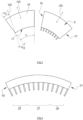
- Figure 2 shows schematically the tread molding section or portion 3 for molding a tire tread divided in a tire circumferential direction into a plurality of mold segments 15.
- the tread molding section or portion 3 may comprise from 4 to 20 mold segments 15; preferably, from 5 to 12 mold segments 15; more preferably, from 6 to 10 mold segments 15; more preferably, from 6 to 9 mold segments 15.
- the tread molding section or portion 3 illustrated in Figure 2 is divided into 9 mold segments 15 which are movable to open and close the tire mold 1.
- Each mold segment 15 extends along its length about a portion of the tire's circumference, so that each mold segment has an (radially) inner face curved along the circumferential direction according to an arc defined by an angle ⁇ .
- the tire mold 1 has 6 mold segments, each mold segment covers a portion of the tire's circumference defined by an arc with an angle ⁇ of 60°.
- the tire mold has 9 mold segments, each mold segment covering a portion of the tire's circumference defined by an arc with an angle ⁇ of 40°.
- the circumference is 360 degrees and the value of the angle ⁇ is ranging from 90° to 18°; preferably from 72° to 30°; more preferably from 60° to 40° or from 60° to 20°.
- Each mold segment 15 can be moved in translation in a radial direction of the molded tire.
- the direction in which each mold segment 15 is movable is the operating direction of the mold segment 15 and is denoted OD in Figure 2 .
- the operating direction is the radial direction of a tire as determined at the center of the mold segment along its length.
- the operating direction is parallel to the radial direction as determined at the center of the mold segment along its length wherein "parallel" includes small angles from 0° to 8°; for example, from more than 0° to 5° or from 1° to 5° or preferably from 0° to 2°.
- the mold segments 15 are moved in contraction to close the tire mold and in expansion (i.e. in the opposite direction) to open the tire mold.
- Each mold segment 15 is therefore movable in a respective operation direction between an opened position wherein the mold segments 15 are spaced from each other (i.e. away from each other) and a closed position wherein two neighboring mold segments 15 are in contact with each other by one of their transverse edges.
- Figure 2 shows the tire mold in the closed position wherein the transverse edges of two adjacent mold segments 15 are in contact with each other, in order to form a continuous tread mold portion 3.
- the transverse edges are preferably perpendicular to the circumferential direction.
- the transverse edges are preferably straight.
- Each mold segment 15 comprises a first transverse edge and a second transverse edge.
- the tread pattern is asymmetrical and/or directional, the mold segment 15 needs to be oriented in the given direction so that the first transverse edge of the mold segment is in contact with the second transverse edge of the neighboring mold segment when the tire mold is closed.
- Each mold segment comprises a body with an inner face that molds the tire. It is understood that the inner face of the mold segment will therefore show a corresponding curvature along the length of the mold segment as schematically visible in Figure 2 , but also a curvature along the width of the mold segment as schematically visible in Figure 1 .
- the inner face is equipped with a plurality of blades for molding the tread pattern.
- the blades extend from the inner face into the tire mold. They have one end attached to the inner face (i.e. the proximal end) and one free end (i.e. the distal end). Blades may have any direction depending on the tread pattern that is desired.
- the mold segments may comprise one or more longitudinal ribs 13 (shown on Figure 1 ) to mold circumferential grooves, one or more longitudinal blades to mold circumferential sipes, one or more lateral ribs to mold transversal grooves and one or more laterally extending blades to mold transversal sipes on a tread surface of the green tire.
- the transversal grooves or sipes are extending in directions intersecting circumferential grooves and sipes provided on the tread surface.
- the transversal grooves or sipes may be not necessarily perpendicular to the circumferential grooves or sipes, i.e. they may extend in directions inclined to the circumferential grooves or sipes.
- the transversal sipes have a width smaller than the transversal grooves so that the laterally extending blades are thinner than the lateral ribs.
- At least one mold segment comprises one or more longitudinal ribs or one or more longitudinal blades for molding respectively one or more grooves or one or more sipes extending in the circumferential direction of the tire, and wherein said one or more longitudinal ribs or one or more longitudinal blades are parallel to the operating direction.
- the mold segments 15 comprise laterally extending blades arranged on the inner face 17 of the mold segment 15.
- Laterally extending blades may comprise curves or corners but extend mainly in the width direction of the mold segments 15.
- One or more laterally extending blades to mold transversal sipes on a tread surface of the green tire can be parallel to the axial direction or have an angle with the axial direction that is up to 50°.
- one or more laterally extending blades extend along the width of the mold segment in a direction that has an angle with the axial direction of the tire that is ranging from 0° to 50°; for example, from more than 0° to 45°; for example, from 0° to 40°; for example, from 1° to 40°; for example, from 5° to 35°; for example, from 10° to 30°.
- one or more laterally extending blades are parallel to the axial direction wherein "parallel" includes small angles from 0° to 8°; for example, from more than 0° to 5° or from 1° to 5°.
- any laterally extending blades positioned on the transverse edges of the mold segment and which extend into the tire mold in the radial direction would have an angle with the operating direction with a value of about half the angle ⁇ , wherein the angle ⁇ corresponds to the arc defining the portion of the tire's circumference covered by the mold segment.
- Said angle ⁇ /2 can be very large, for example, ⁇ /2 is up to 30 ° if the mold comprises 6 mold segments each being defined by an arc with an angle ⁇ of 60°.
- the angle ⁇ /2 is up to 20° if the mold comprises 9 mold segments each being defined by an arc with an angle ⁇ of 40°.
- the present disclosure provides for adapting the angle of at least a part of the laterally extending blades to be parallel to the operating direction or to form an angle ⁇ with the operating direction that is less than ⁇ /2 with the angle ⁇ being the arc's angle defining the portion of the tire's circumference covered by the mold segment.
- the angle ⁇ is less than 30° for a tire mold comprising 6 mold segments.
- the angle ⁇ is less than 20° for a tire mold comprising 9 mold segments.
- the angle ⁇ is less than ⁇ /3, with preference less than ⁇ /4.
- the angle ⁇ with the operating direction is at most 18 degrees, preferably at most 15°, more preferably at most 12°, and most preferably at most 10°.
- the angle ⁇ with the operating direction being 0° means that the laterally extending blades extend into a direction parallel to the operating direction.
- the angle ⁇ with the operating direction is preferably ranging from 5° to less than 20°; for example, from 8° to 18° degrees; or from 5° to 15°.
- the laterally extending blades of a mold segment that extend from the inner face in a direction parallel to the operating direction.
- at least a part of the laterally extending blades of a mold segment has an angle ⁇ wherein the laterally extending blades are not parallel to the operating direction but have an angle with the operating direction that is reduced by comparison with the angle between the radial direction and the operating direction.
- the laterally extending blades that have an angle ⁇ with the operating direction are hereinafter called the inclined laterally extending blades.
- the laterally extending blades are distributed along the length of a mold segment, for example, in rows, e.g. successive rows, wherein the mold segment comprises a first transverse edge and a second transverse edge.
- the first transverse edge of a mold segment is located in contact with the second transverse edge of the neighboring mold segment when the mold segments are located in their closed position.
- the laterally extending blades located at a transverse edge are the closest to said transverse edge.
- the mold segment can therefore be divided according to its length between a first end portion 25 that includes the first transverse edge 19 of the mold segment 15, a second end portion 29 that includes the second transverse edge 21 and a central portion 27 located between the first and the second end portions 25, 29.
- the central portion 27 has a length ranging from 5% to 50% of the total length of the mold segment; for example, from 10% to 50%; for example, from 10% to 40%; for example, from 15% to 35%; for example, from 20% to 30%.
- Each of the first end portion 25 and the second end portion 29 can have a length ranging from 25% to 47.5% of the total length of the mold segment; for example, from 25% to 45%; for example, from 30% to 45%; for example, from 32.5% to 45.5%; for example, from 35% to 40%.
- the length of the first end portion 25 and the second end portion 29 can be the same or different.
- the laterally extending blades of the central portion 27 extend in a direction parallel to the operating direction, whereas the laterally extending blades of the first end portion 25 and the second end portion 29 extend with an angle ⁇ with the operating direction.
- all the laterally extending blades of the first end portion 25 or of the second end portion 29 extend in a direction parallel the direction of the laterally extending blades located at the first transverse edge or at the second transverse edge respectively; wherein the laterally extending blades located at the first or second transverse edges 25, 29 form an angle ⁇ with the operating direction that is at most 12° or at most 10°.
- all the laterally extending blades of the first end portion 25 or the second end portion 29 extend in a direction forming an angle ⁇ with the operating direction wherein the angle ⁇ is maximal for the laterally extending blades located at a transverse edge and continuously decreases for the next laterally extending blades that are successive in the circumferential direction up to the central portion 27 wherein the laterally extending blades are parallel to the operating direction.
- the value of the angle ⁇ is continuously decreasing from the laterally extending blades located at a transverse edge to the laterally extending blades that extend according to the operating direction so that the first blades located at a transverse edge have a maximal angle ⁇ that is less than ⁇ /3, with preference less than ⁇ /4.
- the value of the angle ⁇ is maximal, e.g. having at most 18°, preferably at most 15°, more preferably at most 12°, and most preferably at most 10°.
- the value of the angle ⁇ is continuously decreasing from the laterally extending blades located at the transverse edge to the laterally extending blades that extend according to the operating direction so that the laterally extending blades located at a transverse edge (i.e. at the first transverse edge and/or at the second transverse edge) have an angle ⁇ with the operating direction which is at most 18°, preferably at most 15°, more preferably at most 12°, and most preferably at most 10°.
- each segment comprises a plurality of laterally extending blades parallel to the operating direction and a plurality of laterally extending blades inclined relative to the operating direction of said segment.
- the inclined blades have a thickness superior to the thickness of the laterally extending blades which are parallel to the operating direction.
- the thickness of an inclined blade is ranging from 1.05 to 1.50 times the thickness of the laterally extending blades parallel to the operating direction, with preference from 1.10 to 1.40 times or from 1.20 to 1.30 times.
- the use of thinner blades on at least the central portion 27 of the mold segment allows increasing the number of blades and as a result, may increase the overall performance of the tire.
- the use of thicker blades on the first and second end portion allows increasing the resistance to breakage of these laterally extending blades.
- the density of the laterally extending blades in the central portion 27 may be superior to the density of the laterally extending blades in the first end portion 25 or in the second end portion 29 or in both the first and second end portions.
- the density of the laterally extending blades can be uniform along the mold segment or can be greater in the central portion 27 when the thickness of the laterally extending blades is smaller in the central portion 27.
- At least 20% of the laterally extending blades of at least one mold segment may be in the central portion; for example, at least 25%; for example, at least 30%; for example, at least 40%; for example, at least 50% or at least 55%. It is understood that when the density of the laterally extending blades is greater in the central portion, the central portion 27 covering 50% of the total length may comprise more than 50% of the laterally extending blades for example.
- the laterally extending blades located at the transverse edge of a mold segment 15 are configured to interlock between the laterally extending blades located at the transverse edge of the neighboring mold segment 15 when the mold segments 15 are located in their closed position.
- This configuration allows having the laterally extending blades located at a transverse edge to extend in a direction different from the radial direction and at the same time to close the mold without damaging said laterally extending blades.
- only 3 rows of laterally extending blades are schematically represented for each mold segment 15, i.e. located at each transverse edge and at the median (i.e. central) plane.
- Interlocking blades means that the one or more laterally extending blades 31 of the first transverse edge of a mold segment 15 are not aligned in the circumferential direction with the one or more laterally extending blades 33 located at the second transverse edge 21 of the neighboring mold segment 15 so that they can engage or mesh with each other.
- at least one of the first or second transverse edge comprises a single lateral blade. In an embodiment that can be alternative or complementary, at least one of the first or second transverse edge comprises more than one lateral blade.
- a mold segment 15 comprises at its first transverse edge 19 one or more laterally extending blades 31 configured to interlock with one or more laterally extending blades 33 located at the second transverse edge 21 of the neighboring mold segment 15, the one or more laterally extending blades 31 located at the first transverse edge 19 are not aligned in the circumferential direction with the laterally extending blades 33 located at the second transverse edge 21.
- the first transverse edge 19 is devoid of laterally extending blades that face the one or more laterally extending blades 33 located at the second transverse edge 21 and vice versa.
- Reference sign 23 of Figure 5 illustrates the free space between two laterally extending blades that may be left in the axial direction.
- the number of laterally extending blades located at the first transverse edge and/or at the second transverse edge is lower than the number of laterally extending blades located directly behind them in the circumferential direction.
- the laterally extending blades 31, 33 located at the first transverse edge 19 and at the second transverse edge 21 are distributed along the width of the mold segment 15, for example, in an alternating manner.
- the first transverse edge 19 of a mold segment 15 shows a distribution of laterally extending blades 31 that is complementary to the distribution of laterally extending blades 33 located at the second transverse edge 21 of the neighboring mold segment 15.
- all the mold segments 15 of the tire mold are similar and each have the distribution and/or the number of the laterally extending blades 31 located at the first transverse edge 19 being different from the distribution and/or the number of the laterally extending blades 33 located at the second transverse edge 21.
- At least one mold segment comprises a number of laterally extending blades located at the first transverse edge that is greater than the number of laterally extending blades located at the second transverse edge or vice-versa.
- the mold segments 15 are therefore asymmetric with regards to the number and/or distribution of laterally extending blades at each of their transverse edges 19, 21.
- interlocking laterally extending blades located at the transverse edges of the mold segments may allow them to have the same height as the laterally extending blades located in the central portion of the mold segment.
- the laterally extending blades are attached to the mold segment by a proximal end and show a free distal end; and the height of a lateral blade is measured from its proximal end to its distal end.
- laterally extending blades of the first end portion 25 and/or the second end portion 29 that are smaller in height than the laterally extending blades located in the central portion 27. It is also possible that only the laterally extending blades located at each transverse edge have a smaller height.
- At least a part of the laterally extending blades in the first end portion 25 or in the second end portion 29 or in both the first and second end portions has a height that is ranging from 0.5 to 0.9 times the height of the laterally extending blades of the central portion 27; for example, from 0.6 to 0.9 times; for example, from 0.7 to 0.8 times.
- the laterally extending blades can have the same thickness or a different thickness. To improve the robustness of the inclined laterally extending blades, it is possible that they have a greater thickness.
- the thickness of the laterally extending blades that are inclined relative to the operating direction is ranging from 1.05 to 1.50 times the thickness of the laterally extending blades parallel to the operating direction; for example, from 1.10 to 1.40 times; for example, from 1.20 to 1.30 times.
- the thickness of laterally extending blades to form sipes is at most 0.60 mm; preferably at most 0.55 mm; more preferably at most 0.50 mm; even more preferably at most 0.45 mm; and most preferably at most 0.40 mm.
- the thickness of laterally extending blades to form sipes is at most 0.60 mm for mold segments used to produce tires for passenger cars, but can be at most 0.80 mm in mold segments used to produce tires for light trucks and at most 2.0 mm in mold segments used to produce tires for trucks.
- the person skilled in the art can adapt the teaching of the disclosure to any size of tire.
- the laterally extending blades that are inclined relative to the operating direction have a thickness superior to the thickness of the laterally extending blades which are parallel to the operating direction. This also allows using thinner laterally extending blades when they extend in the operating direction and therefore to increase the density of the laterally extending blades for example in the central portion.
- the mold segments have according to their length (i.e. according to the circumferential direction) a first end portion, a second end portion and a central portion located between the first and the second end portion; wherein the laterally extending blades of the central portion are extending in the operating direction, and wherein the laterally extending blades of the first end portion 25 or the second end portion 29 or of both the first and second end portions are inclined blades that extend in a direction forming an angle ⁇ with the operating direction wherein the angle ⁇ is less than half of the angle ⁇ ; wherein the laterally extending blades that are inclined relative to the operating direction have a thickness superior than the thickness of the laterally extending blades which are parallel to the operating direction and the density of the laterally extending blades in the central portion is superior to the density of the laterally extending blades in the first end portion 25 or in the second end portion 29 or in both the first and second end portions.
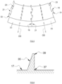
- the laterally extending blades are attached to the mold segment by a proximal end and show a free distal end, wherein the laterally extending blades have a constant thickness along their height (i.e. from their proximal end to their distal end) or have a thickness that is decreasing from their proximal end to their distal end as shown on Figure 6 .
- the thickness of the laterally extending blades refers to the thickness shown by the laterally extending blades at its proximal end 37 unless explicitly stated otherwise.
- the thickness of the laterally extending blades at their proximal end is ranging from 1.05 to 1.50 times the thickness of the laterally extending blades at their distal end; for example, from 1.10 to 1.40 times; for example, from 1.20 to 1.30 times.
- the laterally extending blades 35 having a thickness that is decreasing from their proximal end 37 to their distal end 39, may show on each face a different angle with the inner face 17 of the mold segment.
- each mold segment comprises a plurality of laterally extending blades parallel to the operating direction and a plurality of laterally extending blades inclined relative to the operating direction of said segment.
- the laterally extending blades that are inclined relative to the operating direction have a thickness that is decreasing from their proximal end to their distal end.
- At least one mold segment comprises one or more laterally extending blades that extend according to the operating direction; wherein the thickness of two consecutive laterally extending blades aligned in the circumferential direction is continuously decreasing from the maximal thickness of the laterally extending blades located at a transverse edge to the minimal thickness of the laterally extending blades that extend according to the operating direction.
- the thickness of the laterally extending blades located at a transverse edge is the maximal thickness of the laterally extending blades and/or the maximal thickness of laterally extending blades is at most 0.60 mm, preferably at most 0.55 mm, more preferably at most 0.50 mm, even more preferably at most 0.45 mm, and most preferably at most 0.40 mm.
Landscapes
- Engineering & Computer Science (AREA)
- Mechanical Engineering (AREA)
- Chemical & Material Sciences (AREA)
- Manufacturing & Machinery (AREA)
- Materials Engineering (AREA)
- Moulds For Moulding Plastics Or The Like (AREA)
- Heating, Cooling, Or Curing Plastics Or The Like In General (AREA)
Claims (5)
- Für einen Luftreifen bestimmte Form, die einen Formabschnitt für eine Lauffläche umfasst, der in einer Umfangsrichtung des Reifens in eine Anzahl von Formsegmenten (15) unterteilt ist, die jeweils eine Innenfläche (17) besitzen, die in der Umfangsrichtung entlang eines Bogens gekrümmt ist, der durch einen Winkel α definiert ist ; wobei jedes Formsegment (15) zwei Querkanten (19, 21) besitzt und in einer jeweiligen Betriebsrichtung zwischen (i) einer offenen Position, in der die Formsegmente (15) voneinander beabstandet sind, und (ii) einer geschlossenen Position, in der zwei benachbarte Formsegmente (15) über eine ihrer Querkanten (19, 21) miteinander in Kontakt kommen, bewegbar ist ; wobei jedes der Formsegmente (15) eine Anzahl von sich in der seitlichen Richtung erstreckenden Klingen umfasst, die Vorsprünge in Bezug auf die Innenfläche (17) des Formsegments (15) bilden, um Lamellen zu bilden, die sich in der seitlichen Richtung auf einer Laufflächenoberfläche des Luftreifens erstrecken; wobei die Formsegmente (15) in ihrer Längsrichtung einen ersten Endabschnitt (25), einen zweiten Endabschnitt (29) und einen Mittelabschnitt (27) zwischen dem ersten Endabschnitt (25) und dem zweiten Endabschnitt (29) besitzen; wobei die Flügel des Mittelabschnitts (27), die sich in der seitlichen Richtung erstrecken, sich in der Betriebsrichtung (OD) erstrecken ; und wobei die Klingen eines oder mehrerer Abschnitte, ausgewählt aus dem ersten Endabschnitt (25) und dem zweiten Endabschnitt (29), die sich in der seitlichen Richtung erstrecken, geneigte Klingen darstellen, die sich in einer Richtung erstrecken, die einen Winkel β mit der Betriebsrichtung (OD) bildet; und wobei der Wert des Winkels β weniger als die Hälfte des Wertes des Winkels α beträgt; dadurch gekennzeichnet, dassdie sich in der seitlichen Richtung erstreckende Klingen, die sich an einer ersten Querkante (19) mindestens eines Formsegments (15) befinden, so konfiguriert sind, dass sie mechanisch zwischen sich in der seitlichen Richtung erstreckenden Klingen, die sich an einer zweiten Querkante (21) eines benachbarten Formsegments (15) befinden, eingreifen, wenn die Formsegmente (15) sich in der geschlossenen Position befinden; und/odereine oder mehrere sich in der seitlichen Richtung erstreckende Klingen, die sich an einer ersten Querkante (19) von mindestens einem der Formsegmente (15) befinden, nicht in der Umfangsrichtung mit einer oder mehreren sich in der seitlichen Richtung erstreckenden Klingen, die sich an einer benachbarten zweiten Querkante (21) eines benachbarten Formsegments (15) befinden, ausgerichtet sind; und/oderdie Anzahl der sich in der seitlichen Richtung erstreckenden Klingen, die sich an der ersten Querkante (19) eines ersten der Formsegmente (15) befinden, sich von der Anzahl der sich in der seitlichen Richtung erstreckenden Klingen, die sich an einer zweiten Querkante (21) eines zweiten Formsegments (15) befinden, das dem ersten Formsegment (15) benachbart ist, unterscheidet; wobei die zweite Querkante (21) an die erste Querkante (19) angrenzt; und/oderdie Anzahl der sich in der seitlichen Richtung erstreckenden Klingen, die an einer oder mehreren der Querkanten (19, 21) von mindestens einem Formsegment (15) angeordnet sind, geringer ist als die Anzahl der sich in der seitlichen Richtung erstreckenden Klingen, die in der Umfangsrichtung direkt hinter den sich in der seitlichen Richtung erstreckenden Klingen angeordnet sind.
- Für einen Luftreifen bestimmte Form nach Anspruch 1, dadurch gekennzeichnet, dass sie eines oder mehrere der Elemente besitzt, die ausgewählt sind aus:einem Mittelabschnitt (27) der eine Länge aufweist, die einen Wert darstellt, der innerhalb eines Bereichs von 10 % bis 50 % der Gesamtlänge des Formsegments (15) liegt ;geneigten Klingen, die eine Dicke besitzen, die größer ist als die Dicke der sich in der seitlichen Richtung erstreckenden Klingen, die parallel zu der Betriebsrichtung (OD) sind.
- Für einen Luftreifen bestimmte Form nach Anspruch 1 oder 2, dadurch gekennzeichnet, dass:eine Dichte der Klingen, die sich in der seitlichen Richtung erstrecken, in dem Mittelabschnitt (27) größer ist als die Dichte der Klingen, die sich in der seitlichen Richtung in einem oder mehreren Endabschnitten erstrecken, die aus dem ersten Endabschnitt (25) und dem zweiten Endabschnitt (29) ausgewählt sind; und/odermindestens ein Teil der Klingen, die sich in der seitlichen Richtung in einem oder mehreren Endabschnitten erstrecken, die aus dem ersten Endabschnitt (25) und dem zweiten Endabschnitt (29) ausgewählt sind, eine Höhe besitzt, die geringer ist als die Höhe der Klingen des mittleren Abschnitts (27), die sich in der seitlichen Richtung erstrecken; und/oderder Wert des Winkels α innerhalb eines Bereichs von 60° bis 40° liegt und/oder der Wert des Winkels β höchstens 18° beträgt.
- Für einen Luftreifen bestimmte Form nach einem oder mehreren der vorhergehenden Ansprüche, dadurch gekennzeichnet, dass das mindestens eine Formsegment (15) mittels eines dreidimensionalen Drucks hergestellt wird.
- Luftreifen, der über der Luftreifen bestimmte Form gemäß einem oder mehreren der vorhergehenden Ansprüche geformt wird, wobei der Luftreifen gegebenenfalls aus einem Ganzjahresreifen oder einem Winterreifen ausgewählt ist.
Applications Claiming Priority (2)
| Application Number | Priority Date | Filing Date | Title |
|---|---|---|---|
| US202063127253P | 2020-12-18 | 2020-12-18 | |
| EP21212443.2A EP4015203B1 (de) | 2020-12-18 | 2021-12-06 | Reifenform |
Related Parent Applications (1)
| Application Number | Title | Priority Date | Filing Date |
|---|---|---|---|
| EP21212443.2A Division EP4015203B1 (de) | 2020-12-18 | 2021-12-06 | Reifenform |
Publications (3)
| Publication Number | Publication Date |
|---|---|
| EP4292801A2 EP4292801A2 (de) | 2023-12-20 |
| EP4292801A3 EP4292801A3 (de) | 2024-02-28 |
| EP4292801B1 true EP4292801B1 (de) | 2025-05-21 |
Family
ID=78821823
Family Applications (2)
| Application Number | Title | Priority Date | Filing Date |
|---|---|---|---|
| EP23199939.2A Active EP4292801B1 (de) | 2020-12-18 | 2021-12-06 | Reifenform |
| EP21212443.2A Active EP4015203B1 (de) | 2020-12-18 | 2021-12-06 | Reifenform |
Family Applications After (1)
| Application Number | Title | Priority Date | Filing Date |
|---|---|---|---|
| EP21212443.2A Active EP4015203B1 (de) | 2020-12-18 | 2021-12-06 | Reifenform |
Country Status (3)
| Country | Link |
|---|---|
| US (2) | US11850813B2 (de) |
| EP (2) | EP4292801B1 (de) |
| CN (1) | CN114643730B (de) |
Families Citing this family (2)
| Publication number | Priority date | Publication date | Assignee | Title |
|---|---|---|---|---|
| EP4292801B1 (de) * | 2020-12-18 | 2025-05-21 | The Goodyear Tire & Rubber Company | Reifenform |
| JP2025169610A (ja) * | 2024-05-01 | 2025-11-14 | 住友ゴム工業株式会社 | 重荷重用タイヤ及び重荷重用タイヤの製造方法 |
Family Cites Families (19)
| Publication number | Priority date | Publication date | Assignee | Title |
|---|---|---|---|---|
| US4279794A (en) | 1979-04-26 | 1981-07-21 | Hercules Incorporated | Sizing method and sizing composition for use therein |
| US4287930A (en) * | 1980-04-11 | 1981-09-08 | The Goodyear Tire & Rubber Company | Tire and method of reinforcement |
| US4879794A (en) * | 1987-12-28 | 1989-11-14 | Unarco Industries, Inc. | Method of making shock absorbing wheels |
| FR2762539A1 (fr) | 1997-04-24 | 1998-10-30 | Michelin & Cie | Element moulant un motif dans une bande de roulement |
| US7090735B2 (en) | 2001-08-06 | 2006-08-15 | Bridgestone/Firestone North American Tire, Llc | Method of compensating for residual aligning torque (RAT) |
| JP3746011B2 (ja) * | 2002-03-18 | 2006-02-15 | 日本碍子株式会社 | タイヤ溝形成用金具が鋳ぐるまれた自動車用タイヤ成形用金型およびその製造方法 |
| JP4450793B2 (ja) | 2003-05-13 | 2010-04-14 | 株式会社ブリヂストン | タイヤ加硫金型および空気入りタイヤ |
| JP4411975B2 (ja) * | 2004-01-09 | 2010-02-10 | 横浜ゴム株式会社 | 空気入りタイヤ及びタイヤ金型 |
| JP4346084B2 (ja) | 2004-07-06 | 2009-10-14 | 東洋ゴム工業株式会社 | タイヤ成型用金型 |
| JP2007044946A (ja) * | 2005-08-09 | 2007-02-22 | Bridgestone Corp | タイヤ加硫用金型 |
| JP4950491B2 (ja) * | 2005-12-29 | 2012-06-13 | 住友ゴム工業株式会社 | 重荷重用タイヤ |
| JP5010385B2 (ja) | 2007-08-02 | 2012-08-29 | 東洋ゴム工業株式会社 | タイヤ成型用金型、およびそれを用いた空気入りタイヤ |
| JP5647646B2 (ja) * | 2012-06-08 | 2015-01-07 | 住友ゴム工業株式会社 | タイヤの加硫金型及び空気入りタイヤの製造方法 |
| US20140265033A1 (en) | 2013-03-15 | 2014-09-18 | Michelin Recherche Et Technique S.A. | Method for improved tire mold manufacturing |
| FR3014735B1 (fr) | 2013-12-17 | 2016-11-04 | Michelin & Cie | Element de moulage comprenant des moyens de coupe pour mouler et vulcaniser une bande de roulement |
| DE102014216962A1 (de) * | 2014-08-26 | 2016-03-03 | Continental Reifen Deutschland Gmbh | Vulkanisationswerkzeug |
| JP7144308B2 (ja) * | 2018-12-19 | 2022-09-29 | 株式会社ブリヂストン | 加硫成形用金型 |
| EP3941729B1 (de) * | 2019-03-20 | 2023-08-30 | Bridgestone Americas Tire Operations, LLC | Gegenmassnahme gegen ungleichmässigen verschleiss und lärm |
| EP4292801B1 (de) * | 2020-12-18 | 2025-05-21 | The Goodyear Tire & Rubber Company | Reifenform |
-
2021
- 2021-12-06 EP EP23199939.2A patent/EP4292801B1/de active Active
- 2021-12-06 EP EP21212443.2A patent/EP4015203B1/de active Active
- 2021-12-07 US US17/544,461 patent/US11850813B2/en active Active
- 2021-12-17 CN CN202111549304.XA patent/CN114643730B/zh active Active
-
2023
- 2023-11-15 US US18/509,919 patent/US12447703B2/en active Active
Also Published As
| Publication number | Publication date |
|---|---|
| EP4015203A3 (de) | 2022-07-06 |
| US11850813B2 (en) | 2023-12-26 |
| US12447703B2 (en) | 2025-10-21 |
| US20240083127A1 (en) | 2024-03-14 |
| US20220194038A1 (en) | 2022-06-23 |
| CN114643730B (zh) | 2025-02-18 |
| EP4015203B1 (de) | 2023-10-11 |
| CN114643730A (zh) | 2022-06-21 |
| EP4015203A2 (de) | 2022-06-22 |
| EP4292801A2 (de) | 2023-12-20 |
| EP4292801A3 (de) | 2024-02-28 |
Similar Documents
| Publication | Publication Date | Title |
|---|---|---|
| KR100326193B1 (ko) | 타이어트레드용몰드와타이어몰딩방법 | |
| US12447703B2 (en) | Tire mold | |
| US5327953A (en) | Pneumatic tires with reduced side depth at defined locations | |
| US7628598B2 (en) | Tire mold and pneumatic tire using the same | |
| JP5115299B2 (ja) | 空気入りタイヤおよびタイヤ成形金型 | |
| JP4145337B2 (ja) | 空気入りタイヤ | |
| EP1106395B1 (de) | Luftreifen | |
| EP0726174A1 (de) | Luftreifen und Verfahren zu seiner Herstellung | |
| CN101687444B (zh) | 包括分段刀槽花纹的轮胎 | |
| US11685193B2 (en) | Tire tread for HGV trailer | |
| US10870248B2 (en) | Non-symmetrical tread ring parting line mold | |
| CN101024368B (zh) | 充气轮胎及其制造方法 | |
| JP2012011690A (ja) | タイヤ加硫用モールドおよび空気入りタイヤ | |
| JP2012101383A (ja) | タイヤ加硫用モールドおよび空気入りタイヤ | |
| EP1872975B1 (de) | Reifenlauffläche mit Feineinschnitten und Lamelle für Reifenvulkanisierungsform | |
| US7779876B2 (en) | Reinforced blade for use in a vulcanization mold to form a sipe in a tire | |
| WO2018029727A1 (ja) | タイヤ加硫金型、タイヤ加硫装置及びタイヤの製造方法 | |
| JPS62242508A (ja) | 重荷重用空気入りタイヤの製造方法 | |
| JP2002052537A (ja) | 空気入りタイヤの加硫用金型 | |
| JPH0234409A (ja) | 空気入りタイヤ及びその加硫成形用金型 | |
| JPH0447907A (ja) | 重荷重用空気入りタイヤ成形用金型とその重荷重用空気入りタイヤ | |
| JP7187325B2 (ja) | タイヤモールド及びタイヤ製造方法 | |
| EP4580891A1 (de) | Gewellte reifenlamelle für verbesserte reifenleistung und ökonomische formherstellung | |
| KR20250107124A (ko) | 프로파일 세그먼트를 생산하기 위한 방법 | |
| JP2004255620A (ja) | タイヤ金型及びそれを用いた空気入りタイヤの製造方法 |
Legal Events
| Date | Code | Title | Description |
|---|---|---|---|
| PUAI | Public reference made under article 153(3) epc to a published international application that has entered the european phase |
Free format text: ORIGINAL CODE: 0009012 |
|
| STAA | Information on the status of an ep patent application or granted ep patent |
Free format text: STATUS: THE APPLICATION HAS BEEN PUBLISHED |
|
| AC | Divisional application: reference to earlier application |
Ref document number: 4015203 Country of ref document: EP Kind code of ref document: P |
|
| AK | Designated contracting states |
Kind code of ref document: A2 Designated state(s): AL AT BE BG CH CY CZ DE DK EE ES FI FR GB GR HR HU IE IS IT LI LT LU LV MC MK MT NL NO PL PT RO RS SE SI SK SM TR |
|
| PUAL | Search report despatched |
Free format text: ORIGINAL CODE: 0009013 |
|
| AK | Designated contracting states |
Kind code of ref document: A3 Designated state(s): AL AT BE BG CH CY CZ DE DK EE ES FI FR GB GR HR HU IE IS IT LI LT LU LV MC MK MT NL NO PL PT RO RS SE SI SK SM TR |
|
| RIC1 | Information provided on ipc code assigned before grant |
Ipc: B29D 30/06 20060101AFI20240119BHEP |
|
| STAA | Information on the status of an ep patent application or granted ep patent |
Free format text: STATUS: REQUEST FOR EXAMINATION WAS MADE |
|
| 17P | Request for examination filed |
Effective date: 20240801 |
|
| RBV | Designated contracting states (corrected) |
Designated state(s): AL AT BE BG CH CY CZ DE DK EE ES FI FR GB GR HR HU IE IS IT LI LT LU LV MC MK MT NL NO PL PT RO RS SE SI SK SM TR |
|
| GRAP | Despatch of communication of intention to grant a patent |
Free format text: ORIGINAL CODE: EPIDOSNIGR1 |
|
| STAA | Information on the status of an ep patent application or granted ep patent |
Free format text: STATUS: GRANT OF PATENT IS INTENDED |
|
| INTG | Intention to grant announced |
Effective date: 20241220 |
|
| GRAS | Grant fee paid |
Free format text: ORIGINAL CODE: EPIDOSNIGR3 |
|
| GRAA | (expected) grant |
Free format text: ORIGINAL CODE: 0009210 |
|
| STAA | Information on the status of an ep patent application or granted ep patent |
Free format text: STATUS: THE PATENT HAS BEEN GRANTED |
|
| AC | Divisional application: reference to earlier application |
Ref document number: 4015203 Country of ref document: EP Kind code of ref document: P |
|
| AK | Designated contracting states |
Kind code of ref document: B1 Designated state(s): AL AT BE BG CH CY CZ DE DK EE ES FI FR GB GR HR HU IE IS IT LI LT LU LV MC MK MT NL NO PL PT RO RS SE SI SK SM TR |
|
| REG | Reference to a national code |
Ref country code: GB Ref legal event code: FG4D |
|
| REG | Reference to a national code |
Ref country code: CH Ref legal event code: EP |
|
| REG | Reference to a national code |
Ref country code: DE Ref legal event code: R096 Ref document number: 602021031331 Country of ref document: DE |
|
| REG | Reference to a national code |
Ref country code: IE Ref legal event code: FG4D |
|
| REG | Reference to a national code |
Ref country code: NL Ref legal event code: MP Effective date: 20250521 |
|
| PG25 | Lapsed in a contracting state [announced via postgrant information from national office to epo] |
Ref country code: FI Free format text: LAPSE BECAUSE OF FAILURE TO SUBMIT A TRANSLATION OF THE DESCRIPTION OR TO PAY THE FEE WITHIN THE PRESCRIBED TIME-LIMIT Effective date: 20250521 Ref country code: PT Free format text: LAPSE BECAUSE OF FAILURE TO SUBMIT A TRANSLATION OF THE DESCRIPTION OR TO PAY THE FEE WITHIN THE PRESCRIBED TIME-LIMIT Effective date: 20250922 Ref country code: ES Free format text: LAPSE BECAUSE OF FAILURE TO SUBMIT A TRANSLATION OF THE DESCRIPTION OR TO PAY THE FEE WITHIN THE PRESCRIBED TIME-LIMIT Effective date: 20250521 |
|
| REG | Reference to a national code |
Ref country code: LT Ref legal event code: MG9D |
|
| PG25 | Lapsed in a contracting state [announced via postgrant information from national office to epo] |
Ref country code: GR Free format text: LAPSE BECAUSE OF FAILURE TO SUBMIT A TRANSLATION OF THE DESCRIPTION OR TO PAY THE FEE WITHIN THE PRESCRIBED TIME-LIMIT Effective date: 20250822 Ref country code: NO Free format text: LAPSE BECAUSE OF FAILURE TO SUBMIT A TRANSLATION OF THE DESCRIPTION OR TO PAY THE FEE WITHIN THE PRESCRIBED TIME-LIMIT Effective date: 20250821 |
|
| PG25 | Lapsed in a contracting state [announced via postgrant information from national office to epo] |
Ref country code: NL Free format text: LAPSE BECAUSE OF FAILURE TO SUBMIT A TRANSLATION OF THE DESCRIPTION OR TO PAY THE FEE WITHIN THE PRESCRIBED TIME-LIMIT Effective date: 20250521 Ref country code: PL Free format text: LAPSE BECAUSE OF FAILURE TO SUBMIT A TRANSLATION OF THE DESCRIPTION OR TO PAY THE FEE WITHIN THE PRESCRIBED TIME-LIMIT Effective date: 20250521 |
|
| PG25 | Lapsed in a contracting state [announced via postgrant information from national office to epo] |
Ref country code: BG Free format text: LAPSE BECAUSE OF FAILURE TO SUBMIT A TRANSLATION OF THE DESCRIPTION OR TO PAY THE FEE WITHIN THE PRESCRIBED TIME-LIMIT Effective date: 20250521 |
|
| PG25 | Lapsed in a contracting state [announced via postgrant information from national office to epo] |
Ref country code: HR Free format text: LAPSE BECAUSE OF FAILURE TO SUBMIT A TRANSLATION OF THE DESCRIPTION OR TO PAY THE FEE WITHIN THE PRESCRIBED TIME-LIMIT Effective date: 20250521 |
|
| PG25 | Lapsed in a contracting state [announced via postgrant information from national office to epo] |
Ref country code: RS Free format text: LAPSE BECAUSE OF FAILURE TO SUBMIT A TRANSLATION OF THE DESCRIPTION OR TO PAY THE FEE WITHIN THE PRESCRIBED TIME-LIMIT Effective date: 20250821 |
|
| PG25 | Lapsed in a contracting state [announced via postgrant information from national office to epo] |
Ref country code: IS Free format text: LAPSE BECAUSE OF FAILURE TO SUBMIT A TRANSLATION OF THE DESCRIPTION OR TO PAY THE FEE WITHIN THE PRESCRIBED TIME-LIMIT Effective date: 20250921 |
|
| PG25 | Lapsed in a contracting state [announced via postgrant information from national office to epo] |
Ref country code: LV Free format text: LAPSE BECAUSE OF FAILURE TO SUBMIT A TRANSLATION OF THE DESCRIPTION OR TO PAY THE FEE WITHIN THE PRESCRIBED TIME-LIMIT Effective date: 20250521 |