EP4287003A2 - Anzeigesteuerungsvorrichtung, Verfahren und Computerprogrammprodukt - Google Patents
Anzeigesteuerungsvorrichtung, Verfahren und Computerprogrammprodukt Download PDFInfo
- Publication number
- EP4287003A2 EP4287003A2 EP23204385.1A EP23204385A EP4287003A2 EP 4287003 A2 EP4287003 A2 EP 4287003A2 EP 23204385 A EP23204385 A EP 23204385A EP 4287003 A2 EP4287003 A2 EP 4287003A2
- Authority
- EP
- European Patent Office
- Prior art keywords
- item
- display
- displayed
- proximity
- input
- Prior art date
- Legal status (The legal status is an assumption and is not a legal conclusion. Google has not performed a legal analysis and makes no representation as to the accuracy of the status listed.)
- Granted
Links
Images





Classifications
-
- G—PHYSICS
- G06—COMPUTING OR CALCULATING; COUNTING
- G06F—ELECTRIC DIGITAL DATA PROCESSING
- G06F3/00—Input arrangements for transferring data to be processed into a form capable of being handled by the computer; Output arrangements for transferring data from processing unit to output unit, e.g. interface arrangements
- G06F3/01—Input arrangements or combined input and output arrangements for interaction between user and computer
- G06F3/048—Interaction techniques based on graphical user interfaces [GUI]
- G06F3/0487—Interaction techniques based on graphical user interfaces [GUI] using specific features provided by the input device, e.g. functions controlled by the rotation of a mouse with dual sensing arrangements, or of the nature of the input device, e.g. tap gestures based on pressure sensed by a digitiser
- G06F3/0488—Interaction techniques based on graphical user interfaces [GUI] using specific features provided by the input device, e.g. functions controlled by the rotation of a mouse with dual sensing arrangements, or of the nature of the input device, e.g. tap gestures based on pressure sensed by a digitiser using a touch-screen or digitiser, e.g. input of commands through traced gestures
- G06F3/04886—Interaction techniques based on graphical user interfaces [GUI] using specific features provided by the input device, e.g. functions controlled by the rotation of a mouse with dual sensing arrangements, or of the nature of the input device, e.g. tap gestures based on pressure sensed by a digitiser using a touch-screen or digitiser, e.g. input of commands through traced gestures by partitioning the display area of the touch-screen or the surface of the digitising tablet into independently controllable areas, e.g. virtual keyboards or menus
-
- G—PHYSICS
- G06—COMPUTING OR CALCULATING; COUNTING
- G06F—ELECTRIC DIGITAL DATA PROCESSING
- G06F3/00—Input arrangements for transferring data to be processed into a form capable of being handled by the computer; Output arrangements for transferring data from processing unit to output unit, e.g. interface arrangements
- G06F3/01—Input arrangements or combined input and output arrangements for interaction between user and computer
- G06F3/048—Interaction techniques based on graphical user interfaces [GUI]
- G06F3/0481—Interaction techniques based on graphical user interfaces [GUI] based on specific properties of the displayed interaction object or a metaphor-based environment, e.g. interaction with desktop elements like windows or icons, or assisted by a cursor's changing behaviour or appearance
- G06F3/04812—Interaction techniques based on cursor appearance or behaviour, e.g. being affected by the presence of displayed objects
-
- G—PHYSICS
- G06—COMPUTING OR CALCULATING; COUNTING
- G06F—ELECTRIC DIGITAL DATA PROCESSING
- G06F3/00—Input arrangements for transferring data to be processed into a form capable of being handled by the computer; Output arrangements for transferring data from processing unit to output unit, e.g. interface arrangements
- G06F3/01—Input arrangements or combined input and output arrangements for interaction between user and computer
- G06F3/048—Interaction techniques based on graphical user interfaces [GUI]
- G06F3/0481—Interaction techniques based on graphical user interfaces [GUI] based on specific properties of the displayed interaction object or a metaphor-based environment, e.g. interaction with desktop elements like windows or icons, or assisted by a cursor's changing behaviour or appearance
- G06F3/0482—Interaction with lists of selectable items, e.g. menus
-
- G—PHYSICS
- G06—COMPUTING OR CALCULATING; COUNTING
- G06F—ELECTRIC DIGITAL DATA PROCESSING
- G06F3/00—Input arrangements for transferring data to be processed into a form capable of being handled by the computer; Output arrangements for transferring data from processing unit to output unit, e.g. interface arrangements
- G06F3/01—Input arrangements or combined input and output arrangements for interaction between user and computer
- G06F3/048—Interaction techniques based on graphical user interfaces [GUI]
- G06F3/0484—Interaction techniques based on graphical user interfaces [GUI] for the control of specific functions or operations, e.g. selecting or manipulating an object, an image or a displayed text element, setting a parameter value or selecting a range
- G06F3/04842—Selection of displayed objects or displayed text elements
-
- G—PHYSICS
- G06—COMPUTING OR CALCULATING; COUNTING
- G06F—ELECTRIC DIGITAL DATA PROCESSING
- G06F3/00—Input arrangements for transferring data to be processed into a form capable of being handled by the computer; Output arrangements for transferring data from processing unit to output unit, e.g. interface arrangements
- G06F3/01—Input arrangements or combined input and output arrangements for interaction between user and computer
- G06F3/048—Interaction techniques based on graphical user interfaces [GUI]
- G06F3/0487—Interaction techniques based on graphical user interfaces [GUI] using specific features provided by the input device, e.g. functions controlled by the rotation of a mouse with dual sensing arrangements, or of the nature of the input device, e.g. tap gestures based on pressure sensed by a digitiser
- G06F3/0488—Interaction techniques based on graphical user interfaces [GUI] using specific features provided by the input device, e.g. functions controlled by the rotation of a mouse with dual sensing arrangements, or of the nature of the input device, e.g. tap gestures based on pressure sensed by a digitiser using a touch-screen or digitiser, e.g. input of commands through traced gestures
-
- H—ELECTRICITY
- H04—ELECTRIC COMMUNICATION TECHNIQUE
- H04N—PICTORIAL COMMUNICATION, e.g. TELEVISION
- H04N23/00—Cameras or camera modules comprising electronic image sensors; Control thereof
- H04N23/60—Control of cameras or camera modules
- H04N23/62—Control of parameters via user interfaces
-
- H—ELECTRICITY
- H04—ELECTRIC COMMUNICATION TECHNIQUE
- H04N—PICTORIAL COMMUNICATION, e.g. TELEVISION
- H04N23/00—Cameras or camera modules comprising electronic image sensors; Control thereof
- H04N23/60—Control of cameras or camera modules
- H04N23/63—Control of cameras or camera modules by using electronic viewfinders
-
- H—ELECTRICITY
- H04—ELECTRIC COMMUNICATION TECHNIQUE
- H04N—PICTORIAL COMMUNICATION, e.g. TELEVISION
- H04N23/00—Cameras or camera modules comprising electronic image sensors; Control thereof
- H04N23/60—Control of cameras or camera modules
- H04N23/63—Control of cameras or camera modules by using electronic viewfinders
- H04N23/631—Graphical user interfaces [GUI] specially adapted for controlling image capture or setting capture parameters
Definitions
- the present technology relates to a display control device, a display control method, and computer program product, and in particular, relates to a display control device, method, and computer program product that are suitable for use when display control is performed on a display device that can be operated by proximity.
- the present technology is made.
- an apparatus includes a controller that causes a display to display a relation item in response to receiving an indication of a detection of an object's proximity to a displayed item, the displayed item being displayed on a periphery of the display, and changes a displayed form of a portion of the relation item that is proximate to or in contact with the object as the object moves along the relation item.
- the controller is configured to change the displayed form of the relation item when a touch position of the object coincides with the relation item.
- the controller recognizes a proximity response area that is larger than a size of the item, the proximity response area being an area that is a criterion used when detecting if the object is proximate to the item.
- the proximity response area is a rectangular area that surrounds the item.
- the controller causes the display to highlight at least the item when the object is detected to be proximate to the item.
- the controller causes an options menu to be displayed when the object is detected as being proximate to the item.
- the options menu is translucently superimposed on an image displayed on the display, and the relation item includes the options menu.
- the proximity response area at least includes an area occupied by the options menu and the item.
- the options menu includes a plurality of icons having respective contact response areas, and the proximity response area at least including an area occupied by the respective contact response areas.
- the controller causes a selected icon of the plurality of icons to be highlighted on the display when the object is positioned proximate to the selected icon.
- the controller also causes a function guide to be displayed, the functions guide explains functions assigned to respective menu options on the options menu.
- the options menu is translucently displayed so that a background image remains at least partially visible on the display.
- the display includes an electrostatic touch panel.
- the controller highlights the item by at least one of changing a color, size, shape, design and brightness of the item.
- the options menu includes option icons that are lower in rank than the item.
- the options menu includes user-settable option icons.
- a selection state of the item is not changed.
- the controller changes at least one of the plurality of icons to another icon when the object touches the display.
- the plurality of icons remain present when the object touches the display and the object is then removed from the display by a distance further than a proximity detection range.
- the options menu includes a plurality of icons having respective contact response areas, at least one of the contact response areas being smaller in area than an area occupied by a corresponding icon.
- the controller recognizes a selection state of a function associated with the item when the object is detected proximate to the item, and the controller maintains the selection state even when the object is not moved to be proximate to the options menu.
- the method includes receiving an indication of a detection of an object's proximity to a displayed item; causing a display to display a relation item in response to the receiving, the displayed item being displayed on a periphery of the display, and changing a displayed form of a portion of the relation item that is proximate to or in contact with the object as the object moves along the relation item.
- non-transitory computer storage device embodiment that has instructions stored therein that when executed by a processing circuit implement a process that includes receiving an indication of a detection of an object's proximity to a displayed item; causing a display to display a relation item in response to the receiving, the displayed item being displayed on a periphery of the display, and changing a displayed form of a portion of the relation item that is proximate to or in contact with the object as the object moves along the relation item.
- Fig. 1 is a block diagram illustrating an example of the configuration of an embodiment of a digital camera (digital still camera) 1 to which the present technology is applied.
- a lens unit 11 includes an image-capturing lens, an aperture stop, a focus lens, and the like, and light entering the lens unit 11 is beamed into an imaging element 12.
- the imaging element 12 includes a charge coupled device (CCD), a complementary metal oxide semiconductor (CMOS) imager, or the like, subjects the light from the lens unit 11 to photoelectric conversion, and supplies, to an analog signal processing unit 13, an analog image signal obtained as the result thereof.
- CCD charge coupled device
- CMOS complementary metal oxide semiconductor
- the analog signal processing unit 13 subjects the image signal from the imaging element 12 to analog signal processing such as correlated double sampling processing, automatic gain adjustment processing, and the like, and supplies the image signal subjected to the analog signal processing to an analog/digital (A/D) conversion unit 14.
- analog signal processing such as correlated double sampling processing, automatic gain adjustment processing, and the like
- the A/D conversion unit 14 A/D-converts the image signal from the analog signal processing unit 13, and supplies, to a digital signal processing unit 15, a digital image data obtained as the result thereof.
- the digital signal processing unit 15 subjects the image data from the A/D conversion unit 14 to digital signal processing such as white balance adjustment processing, noise reduction processing, necessary compression-encoding processing (for example, Joint Photographic Experts Group (JPEG) encoding or the like), and the like, and supplies the image data to a display unit 17 in an input-output panel 18 and a recording device 19.
- digital signal processing such as white balance adjustment processing, noise reduction processing, necessary compression-encoding processing (for example, Joint Photographic Experts Group (JPEG) encoding or the like), and the like, and supplies the image data to a display unit 17 in an input-output panel 18 and a recording device 19.
- JPEG Joint Photographic Experts Group
- the input-output panel 18 includes an input unit 16 and a display unit 17.
- the input unit 16 includes a device having a function for receiving (detecting) an input from the outside thereof, namely, for example, an electrostatic touch panel or the like, a set of a light source for light irradiation and a sensor for receiving the reflection of the light, reflected from an object, or the like.
- the input unit 16 detects the proximity and touch (contact) of an object (for example, a finger of a user, a stylus pen used by the user, or the like) from the outside, and supplies a signal (hereinafter, referred to as "operation signal") indicating the proximity or touched position thereof to a CPU 23.
- an object for example, a finger of a user, a stylus pen used by the user, or the like
- operation signal a signal
- the display unit 17 includes a device (display device) for displaying an image, for example, a liquid crystal panel or the like, and displays an image in accordance with image data or the like supplied from the digital signal processing unit 15.
- a device display device for displaying an image, for example, a liquid crystal panel or the like, and displays an image in accordance with image data or the like supplied from the digital signal processing unit 15.
- the input unit 16 and the display unit 1, described above, are integrated with each other, it is possible to display an image in the display unit 17, and in the input unit 16, it is possible to receive an operation input (here, both the proximity and the touch) from the outside with respect to an image displayed on the display unit 17.
- an operation input here, both the proximity and the touch
- an object such as a finger, a stylus pen, or the like used for an input (the proximity or the touch) to the input unit 16 in the input-output panel 18 is called an input tool.
- an arbitrary object may also be used that can be caused to be in proximity and touch so as to specify a position on the input unit 16 in the input-output panel 18.
- a disk such as a Digital Versatile Disc (DVD) or the like
- a removable semiconductor memory such as a memory card or the like
- another removable recording medium (not illustrated)
- the recording device 19 performs recording and reproduction control on the attached recording medium. Namely, the recording device 19 records, in the recording medium, the image data from the digital signal processing unit 15, and reads out and supplies the image data recorded in the recording medium to the digital signal processing unit 15.
- An actuator 20 is a motor that adjusts the focus lens and the aperture stop in the lens unit 11, and is driven by a motor drive 21.
- the motor drive 21 drives the actuator 20 in accordance with the control of the central processing unit (CPU) 23.
- CPU central processing unit
- a TG (Timing Generator) 22 supplies, to the imaging element 12, a timing signal used for adjusting an exposure time and the like in accordance with the control of the CPU 23.
- the CPU 23 controls individual blocks included in the digital camera 1.
- ROM program read only memory
- EEPROM electrically erasable programmable ROM
- An operation unit 24 is a physical button or the like operated by the user, and supplies, to the CPU 23, a signal (hereinafter, referred to as "operation signal") corresponding to the operation of the user.
- the EEPROM 25 stores therein a program and data where the data is an imaging parameter or the like set by the user by operating the operation unit 24 or the like and it is also necessary for the data to be held when the power source of the digital camera 1 is turned off.
- the program ROM 26 stores therein a program to be executed by the CPU 23, or the like.
- a RAM 27 temporarily stores therein data and a program, necessary for the operation of the CPU 23.
- the CPU 23 executes a program recorded in the program ROM 26 or the like, thereby controlling individual portions of the digital camera 1.
- the light entering the lens unit 11 is subjected to photoelectric conversion in the imaging element 12, and an image signal obtained as the result thereof is supplied to the analog signal processing unit 13.
- the image signal from the imaging element 12 is subjected to analog signal processing, and is supplied to the A/D conversion unit 14.
- the image signal from the analog signal processing unit 13 is A/D-converted, and a digital image signal obtained as the result thereof is supplied to the digital signal processing unit 15.
- the image data from the A/D conversion unit 14 is subjected to digital signal processing, and is supplied to the display unit 17 in the input-output panel 18, thereby displaying a corresponding image, namely, a so-called through-the-lens image.
- the CPU 23 executes predetermined processing in accordance with an operation signal from the input unit 16 in the input-output panel 18 or the operation unit 24.
- the CPU 23 performs processing for capturing a still image as a photograph, causes the digital signal processing unit 15 to subject the image data from the A/D conversion unit 14 to compression-encoding processing, and causes the image data to be recorded in a recording medium through the recording device 19.
- the CPU 23 controls the digital signal processing unit 15, thereby causing the image data to be read out from the recording medium through the recording device 19.
- the CPU 23 causes the digital signal processing unit 15 to extend the image data read out from the recording medium, and supplies the image data to the input-output panel 18, thereby causing the image data to be displayed.
- the CPU 23 supplies, to the input-output panel 18 through the digital signal processing unit 15, the image of a graphical user interface (GUI) used for performing the operation of the digital camera 1, the confirmation of various kinds of information, or the like.
- GUI graphical user interface
- data used for the GUI is stored in the EEPROM 25 or the program ROM 26.
- the program to be executed by the CPU 23 can be installed from a removable recording medium to the digital camera 1, or can be downloaded through a network and installed to the digital camera 1.
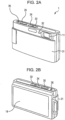
- Figs. 2A and 2B are perspective views illustrating examples of appearance configurations of the digital camera 1 in Fig. 1 .
- Fig. 2A is the perspective view of the front surface side of the digital camera 1 (a side directed toward a subject at the time of image-capturing), and Fig. 2B is the perspective view of the back surface side of the digital camera 1.
- a lens cover 31 is provided so as to cover the front surface of the digital camera 1, and can move up and down.
- the lens cover 31 When the lens cover 31 is located on an upper side, the lens unit 11 and the like are put into states in which the lens unit 11 and the like are covered. In addition, when the lens cover 31 is located on a lower side, the lens unit 11 and the like are exposed and the digital camera 1 is put into a state in which image-capturing can be performed.
- the lens cover 31 is located on the lower side, and the lens unit 11 is exposed.
- An AF illuminator 32 is provided on the left side of the lens unit 11. For example, when the subject is darkened and it is difficult to focus on the subject with an AF function, the AF illuminator 32 emits light (auxiliary light) used for lighting the subject.
- the AF illuminator 32 when a self-timer is used for image-capturing, the AF illuminator 32 also functions as a self-timer lamp that emits light so as to notify the user of image capturing timing based on the self-timer.
- a power button 33 On the upper portion of the digital camera 1, a power button 33, a play button 34, a shutter button (release button) 35, and a zoom lever 36 are provided that are included in the operation unit 24 in Fig. 1 .
- the power button 33 is operated when the power source of the digital camera 1 is switched on and off, and the play button 34 is operated when image data recorded in the recording medium attached to the recording device 19 (in Fig. 1 ) is reproduced.
- the shutter button (release button) 35 is operated when image data is recorded in the recording medium attached to the recording device 19 (in Fig. 1 ) (a photograph (still image) is captured), and the zoom lever 36 is operated when zoom is adjusted.
- the input-output panel 18 On the rear face of the digital camera 1, the input-output panel 18 is provided. On the input-output panel 18, a through-the-lens image, a GUI, or the like is displayed.
- the user can supply various kinds of (operation) inputs to the digital camera 1.
- Fig. 3 is a block diagram illustrating an example of a configuration of a portion of a function realized by the CPU 23 in Fig. 1 by executing a predetermined control program.
- the CPU 23 executes the predetermined control program, thereby realizing a function including functions in which the CPU 23 operates as a display control device 51 and an information processing device 52.
- the display control device 51 In response to an operation on the input unit 16 in the input-output panel 18 (the proximity or touch of the input tool) and an operation on the operation unit 24, the display control device 51 causes the GUI to be displayed on the display unit 17 in the input-output panel 18 through the digital signal processing unit 15, in order to perform the operation of the digital camera 1, the confirmation of various kinds of information, or the like.
- the display control device 51 is configured so as to include an input detection unit 61 and a display control unit 62.
- the input detection unit 61 detects an input (the proximity or touch of the input tool) from the outside to the input unit 16 in the input-output panel 18 and a position or the like on the input unit 16 subjected to the proximity or touch of the input tool.
- the input detection unit 61 supplies, to the display control unit 62, information including these detection results as operation information indicating an operation performed by the user on the input unit 16 in the input-output panel 18.
- the display control unit 62 In response to an operation signal from the operation unit 24 and a user operation indicated by the operation information from the input detection unit 61, the display control unit 62 causes the GUI to be displayed on the display unit 17 in the input-output panel 18 through the digital signal processing unit 15, on the basis of data or the like stored in the EEPROM 25 or the program ROM 26.
- the display control unit 62 recognizes the function of the digital camera 1, the execution of the function being ordered by the user by operating the input unit 16 with respect to the GUI displayed on the display unit 17 in the input-output panel 18. In addition, the display control unit 62 notifies the information processing device 52 of the recognized function.
- the information processing device 52 controls individual portions of the digital camera 1 and causes the individual portions to execute the function given notice of by the display control unit 62.
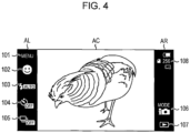
- Fig. 4 is a diagram illustrating a display example of the display screen of the display unit 17 in the input-output panel 18.
- Fig. 4 illustrates a display example of the display screen of the display unit 17 in the input-output panel 18 in a state in which the digital camera 1 is in an image capturing standby state and the input unit 16 is not subjected to the proximity or touch of the input tool.
- the image capturing standby state means a state in which, if the shutter button 35 (in Fig. 2 ) is operated, the capturing of a photograph (still image) is performed (a state in which an image is captured and recorded in the recording medium attached to the recording device 19 (in Fig. 1 )).
- a through-the-lens image is displayed within a central area AC other than vertically long strip-shaped areas AL and AR located on both sides.
- icons 101 to 105 to which predetermined functions are assigned are displayed in tandem with predetermined sizes at predetermined positions within the area AL.
- icons 106 and 107 to which predetermined functions are assigned and an icon group 108 indicating the state or the like of the digital camera 1 are displayed in tandem with predetermined sizes at predetermined positions within the area AR.
- the icon group 108 includes icons indicating the remaining amount of a battery in the digital camera 1, the number of photographs (still images) that can be recorded in a recording medium, an image capturing mode already set, and the like.
- the user can cause the digital camera 1 to execute functions assigned to individual icons.
- the display screen in Fig. 4 is referred to as an image capturing standby screen.
- the lateral directions of the input unit 16 and the display unit 17 in the input-output panel 18 are x-axis directions and the vertical directions thereof are y-axis directions. Accordingly, for example, the lateral direction of the image capturing standby screen in Fig. 4 is the x-axis direction and the vertical direction thereof is the y-axis direction.
- the descriptions of the input unit 16 and the display unit 17 in the input-output panel 18 will be omitted, and the input unit 16 and the display unit 17 in the input-output panel 18 will be simply described as the input-output panel 18.
- a phrase "the display unit 17 in the input-output panel 18 displays an image” is described as a phrase "the input-output panel 18 displays an image”
- a phrase "the input unit 16 in the input-output panel 18 is subjected to the proximity or touch of the input tool” is described as a phrase "the input-output panel 18 is subjected to the proximity or touch of the input tool”.
- an image capturing mode icon 106 used for setting an image capturing mode in the image capturing standby screen in Fig. 4 .
- display control processing will be described that is executed by the digital camera 1 when the image capturing mode icon 106 is operated.
- this processing is started when the power source of the digital camera 1 is turned on or an operation for causing the input-output panel 18 to display the image capturing standby screen is performed on the input-output panel 18 or the operation unit 24.
- processing other than processing relating to the operation performed on the image capturing mode icon 106 for example, processing performed when an icon other than the image capturing mode icon 106 is operated, or the like
- processing other than processing relating to the operation performed on the image capturing mode icon 106 for example, processing performed when an icon other than the image capturing mode icon 106 is operated, or the like
- Step S1 the digital camera 1 displays the image capturing standby screen.
- the imaging element 12 supplies, to the analog signal processing unit 13, an image signal obtained as the result of image capturing.
- the analog signal processing unit 13 subjects the image signal from the imaging element 12 to analog signal processing, and supplies the image signal to the A/D conversion unit 14.
- the A/D conversion unit 14 A/D-converts the image signal from the analog signal processing unit 13, and supplies, to the digital signal processing unit 15, a digital image data obtained as the result thereof.
- the digital signal processing unit 15 subjects the image data from the A/D conversion unit 14 to digital signal processing, and supplies the image data to the input-output panel 18.
- the input-output panel 18 displays a through-the-lens image in the area AC in the image capturing standby screen.
- the display control unit 62 causes the icons 101 to 105 to be displayed in tandem in the area AL in the image capturing standby screen through the digital signal processing unit 15, and causes the image capturing mode icon 106, the icon 107, and the icon group 108 to be displayed in tandem in the area AR in the image capturing standby screen.
- Step S2 the display control unit 62 sets a proximity response area and a contact response area of the image capturing mode icon 106.
- the proximity response area is an area to be a criterion used for detecting the proximity of the input tool to individual icons such as an icon, a character string, a thumbnail, and the like, displayed on the input-output panel 18.
- the contact response area is an area to be a criterion used for detecting the contact of the input tool with individual items displayed on the input-output panel 18.
- Fig. 7 illustrates examples of a proximity response area Rc and a contact response area Rt1, set with respect to the image capturing mode icon 106 in processing performed in Step S2.
- the proximity response area Rc is slightly larger than the physical appearance of the image capturing mode icon 106, and is set to a rectangular area surrounding the image capturing mode icon 106.
- the contact response area Rt1 is set to the same area as the proximity response area Rc.
- Step S3 the input detection unit 61 performs the detection of the proximity position of the input tool on the basis of the operation signal from the input-output panel 18.
- the input detection unit 61 supplies, to the display control unit 62, operation information including the detection result of the proximity position of the input tool.
- Step S4 the display control unit 62 determines whether or not the input tool is caused to be in proximity to the proximity response area Rc of the image capturing mode icon 106. In addition, when the proximity of the input tool to the input-output panel 18 is not detected or the detected proximity position is out of the proximity response area Rc, it is determined that the input tool is not caused to be in proximity to the proximity response area Rc of the image capturing mode icon 106, and the processing returns to Step S3.
- Step S4 After that, in Step S4, until it is determined that the input tool is caused to be in proximity to the proximity response area Rc of the image capturing mode icon 106, processing operations in Steps S3 and S4 are repeatedly executed.
- Step S4 when, in Step S4, the proximity of the input tool to the input-output panel 18 is detected, and the detected proximity position is located within the proximity response area Rc, it is determined that the input tool is caused to be in proximity to the proximity response area Rc of the image capturing mode icon 106, and the processing proceeds to Step S5.
- Step S5 the display control unit 62 causes the display form of the image capturing mode icon 106 to be changed through the digital signal processing unit 15, and causes an options menu to be displayed.
- Fig. 8 illustrates an example of the display screen displayed on the input-output panel 18 in the processing in Step S5 when a finger 121 as the input tool is brought close to the image capturing mode icon 106.
- the image capturing mode icon 106 and the surrounding area thereof are displayed highlighted, and a cursor 131 is displayed so as to surround the image capturing mode icon 106. Accordingly, by bringing the finger 121 close to the image capturing mode icon 106, the user can intuitively recognize that the image capturing mode icon 106 is selected (the image capturing mode icon 106 reacts to the finger 121).
- highlighted display and cursor display are examples, and it may also be indicated in another form that the image capturing mode icon 106 is selected.
- the color, size, design, brightness, or the like of the image capturing mode icon 106 may also be changed.
- the combination of a plurality of the changes of display forms may also be adopted.
- a function guide 132 is displayed that explains a function assigned to the image capturing mode icon 106. Accordingly, the user can easily and swiftly recognize the detail of the function assigned to the image capturing mode icon 106.
- a landscape-oriented options menu 133 extends in a direction perpendicular to the area AR, on the left side of the image capturing mode icon 106, and is displayed so as to be superimposed on the through-the-lens image of the area AC.
- options icons 141 to 143 are displayed abreast with predetermined sizes at predetermined positions within the options menu 133.
- the options icons 141 to 143 are icons relating to the image capturing mode icon 106. More specifically, the options icons 141 to 143 are icons belonging to the lower rank of the image capturing mode icon 106 in the menu system of the digital camera 1. In addition, a function for setting one of the image capturing modes of the digital camera 1 is assigned to each of the options icons 141 to 143.
- the user can freely set the options icons 141 to 143 caused to be displayed on the options menu 133.
- the user can set an icon corresponding to the image capturing mode to an options icon, and cause the icon to be displayed on the options menu 133.
- the function guide 132 and the options menu 133 are translucently displayed so that the through-the-lens image of the background can be seen transparently. Accordingly, even in a state in which the function guide 132 and the options menu 133 are displayed, it is possible to certainly view the through-the-lens image of the background.
- the options menu 133 is displayed that includes the options icons 141 to 143 relating to the image capturing mode icon 106 displayed at the periphery of the proximity position to which the input tool is in proximity.
- Step S6 the display control unit 62 enlarges the proximity response area of the image capturing mode icon 106, and sets the contact response areas of the options icons 141 to 143.
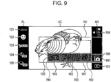
- Fig. 9 illustrates the proximity response area Rc' of the image capturing mode icon 106 and the contact response areas Rt2 to Rt4 of the options icons 141 to 143, set in the processing performed in Step S6.
- the illustration of the cursor 131 and the function guide 132 and the highlighted display of the image capturing mode icon 106 are omitted.
- an area located above the options menu 133 and indicated by a two-dot chain line is an area in which the function guides of the options icons 141 to 143 are displayed, described later with reference to Fig. 10 .
- the proximity response area Rc' of the image capturing mode icon 106 is larger than the proximity response area Rc in Fig. 7 , and is set to a rectangular area including the proximity response area Rc, the options menu 133, and a display area for the function guides of the options icons 141 to 143.
- part or all of the display area for the function guides may not be included in the proximity response area Rc'.
- the contact response areas Rt2 to Rt4 are slightly larger than the physical appearances of the options icons 141 to 143, respectively, and are set to rectangular areas surrounding the options icons 141 to 143, respectively.
- the contact response area Rt1 of the image capturing mode icon 106 and the contact response areas Rt2 to Rt4 of the options icons 141 to 143 are set to almost the same size.
- Step S7 the input detection unit 61 performs the detection of the contact position of the input tool on the basis of the operation signal of the input-output panel 18.
- the input detection unit 61 supplies, to the display control unit 62, operation information including the detection result of the contact position of the input tool.
- Step S8 the display control unit 62 determines whether or not the input tool touches the input-output panel 18, on the basis of the detection result due to the input detection unit 61. When it is determined that the input tool does not touch the input-output panel 18, the processing proceeds to Step S9.
- Step S9 in the same way as in the processing in Step S3, the detection of the proximity position of the input tool is performed, and the operation information including the detection result of the proximity position of the input tool is supplied from the input detection unit 61 to the display control unit 62.
- Step S10 the display control unit 62 determines whether or not the input tool is caused to be proximity to the enlarged proximity response area Rc' of the image capturing mode icon 106. In addition, when the proximity of the input tool to the input-output panel 18 is detected and the detected proximity position is located within the proximity response area Rc', it is determined that the input tool is caused to be proximity to the enlarged proximity response area Rc', and the processing proceeds to Step S11.
- Step S11 in response to the proximity position of the input tool, the display control unit 62 changes the display forms or the like of individual icons through the digital signal processing unit 15.
- the display control unit 62 determines that an icon corresponding to the contact response area is under selection.
- an area defined by a range in the x-axis direction of each of the contact response areas Rt1 to Rt4 and a range in the y-axis direction of the proximity response area Rc' is called a selection determination area.
- the selection determination area of the image capturing mode icon 106 turns out to be an area by a range in the x-axis direction of the contact response area Rt1 and a range in the y-axis direction of the proximity response area Rc'.
- the display control unit 62 changes the display form of an icon determined to be under selection, and causes a function guide for explaining a function assigned to the icon to be displayed.
- the x coordinate of the proximity position of the finger 121 is included in the selection determination area of the options icon 143, and hence it is determined that the options icon 143 is under selection.
- the options icon 143 is displayed highlighted, and the cursor 131 is displayed so as to surround the options icon 143. Namely, with the movement of the finger 121 that is the input tool, the display form of the options icon 143 is changed that is displayed at the periphery of the proximity position of the finger 121.
- the user can intuitively recognize that the selection of an icon is switched and an icon displayed in the proximity of the finger 121 is selected (the icon reacts to the finger 121).
- each options icon is selected.
- a function guide 151 is displayed that explains the name and the content of a function assigned to the options icon 143. Accordingly, the user can easily and swiftly recognize the detail of the function assigned to the options icon 143.
- the function guide 151 is translucently displayed so that the through-the-lens image of the background can be seen transparently. Accordingly, even in a state in which the function guide 151 is displayed, it is possible to certainly view the through-the-lens image of the background.
- the selection state of the icon is not changed and is maintained without change.
- the finger 121 when, from the state illustrated in Fig. 10 , the finger 121 is moved from a position above the options icon 143 to a position above the options icon 142, a state in which the proximity position of the finger 121 is not included in any one of the selection determination areas of the icons occurs on the way. At this time, the selection state of the options icon 143 is maintained without change, and the display screen in Fig. 10 is continuously displayed without change. In addition, when the proximity position of the finger 121 enters the selection determination area of the options icon 142, it is determined that the options icon 142 is under selection, the display form of the options icon 142 is changed, and the function guide of the options icon 142 is displayed.
- Step S8 it is determined that the input tool touches the input-output panel 18 or in Step S10, it is determined that the input tool is not caused to be in proximity to the proximity response area Rc', the processing operations from Step S7 to Step S11 are repeatedly executed.
- the user can freely change selection for the image capturing mode icon 106 and the options icons 141 to 143 by moving the input tool within the proximity response area Rc' with causing the input tool to stay in proximity to the input-output panel 18.
- the display form of the selected icon is changed, and the display of the function guide is switched.
- Step S10 when, in Step S10, the proximity of the input tool to the input-output panel 18 is not detected or the detected proximity position is out of the proximity response area Rc', it is determined that the input tool is not caused to be in proximity to the proximity response area Rc', and the processing proceeds to Step S12.
- Step S12 the display control unit 62 restores the response areas of individual icons. Namely, the display control unit 62 reduces the proximity response area Rc' of the image capturing mode icon 106 to the proximity response area Rc, and cancels the settings of the contact response areas Rt2 to Rt4 of the options icons 141 to 143. Accordingly, the states of the response areas of individual icons are restored from the states in Fig. 9 to the states in Fig. 7 .
- Step S13 the display control unit 62 sets the options menu 133 to nondisplay through the digital signal processing unit 15. Namely, the options menu 133 is closed, the function guide and the cursor 131 are eliminated, and the display screen of the input-output panel 18 is restored to the state in Fig. 4 .
- Step S8 when it is determined that the input tool is caused to touch the input-output panel 18, the processing proceeds to Step S14.
- Step S14 the display control unit 62 determines whether or not the input tool is caused to touch within the enlarged proximity response area Rc' of the image capturing mode icon 106. In addition, when the detected contact position of the input tool is located within the proximity response area Rc', it is determined that the input tool is caused to touch within the proximity response area Rc', and the processing to Step S15.
- Step S15 the display control unit 62 causes the display forms of individual icons or the like to be changed through the digital signal processing unit 15, in response to the contact position of the input tool.
- Step S15 basically the same processing as in Step S12 is performed while the proximity position is just replaced with the contact position. Namely, using the same determination method as in a case in which the proximity position is used, an icon under selection is detected on the basis of the contact position of the input tool. In addition, the display form of the icon under selection is changed, and a function guide corresponding to the icon is displayed.
- Step S16 in the same way as the processing in Step S7, the detection of the contact position of the input tool is performed, and the operation information including the detection result of the contact position of the input tool is supplied from the input detection unit 61 to the display control unit 62.
- Step S17 on the basis of the detection result due to the input detection unit 61, the display control unit 62 determines whether or not the input tool moves away from the input-output panel 18.
- the processing returns to Step S14.
- Step S14 it is determined that the input tool is not caused to touch within the proximity response area Rc' of the image capturing mode icon 106 or, in Step S17, it is determined that input tool moves away from the input-output panel 18, the processing operations from Step S14 to S17 are repeatedly executed.
- the user can freely change selection for the image capturing mode icon 106 and the options icons 141 to 143.
- the display form of the selected icon is changed, and the display of the function guide is switched.
- Step S17 it is determined that the input tool moves away from the input-output panel 18
- the processing proceeds to Step S18.
- this corresponds to a case in which that input tool moves away from the input-output panel 18 with continuing to be caused to touch within the proximity response area Rc'.
- Step S18 the digital camera 1 executes a function assigned to the selected icon. Specifically, first, the display control unit 62 confirms the selection of an icon that has been selected immediately before the input tool moves away from the input-output panel 18. For example, when the input tool moves away from the input-output panel 18 during the selection of the image capturing mode icon 106, the selection of the image capturing mode icon 106 is confirmed. In the same way, when the input tool moves away from the input-output panel 18 during the selection of any one of the options icons 141 to 143, the selection of the options icon under selection is confirmed. Accordingly, on the basis of the contact position immediately before the input tool moves away from the input-output panel 18, the selection of the icon is confirmed.
- the display control unit 62 notifies the information processing device 52 of a function assigned to the icon, for example.
- the information processing device 52 causes the function given notice of to be executed.
- the display control unit 62 causes the input-output panel 18 to display a display screen used for setting the image capturing mode, through the digital signal processing unit 15, for example.
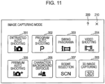
- Fig. 11 illustrates an example of the display screen (hereinafter, referred to as "image capturing mode setting screen") displayed on the input-output panel 18.
- icons 201 to 208 are arrayed in a grid pattern.
- the options icons 141 to 143 displayed on the options menu 133 are selected by the user from among the icons 201 to 208.
- an icon 209 operated when the description of the function of each icon is displayed
- an icon 210 operated when the image capturing mode setting screen is closed and the image capturing standby screen in Fig. 4 is displayed, are displayed in an upper right corner.
- the user can select a desired icon from among the icons 201 to 210 on the image capturing mode selection screen, and confirm the selection thereof.
- the display control unit 62 notifies the information processing device 52 of a function assigned to the icon whose selection is confirmed.
- the information processing device 52 causes the function given notice of to be executed.
- Step S14 when, in Step S14, the detected proximity position of the input tool is out of the proximity response area Rc', it is determined that the input tool touches outside of the proximity response area Rc', and the processing proceeds to Step S19.
- Step S19 in the same way as the processing in Step S12, the response areas of individual icons are restored.
- Step S20 in the same way as the processing in Step S13, the options menu 133 is set to nondisplay.
- Step S21 in the same way as the processing in Step S7, the detection of the contact position of the input tool is performed.
- Step S22 in the same way as the processing in Step S17, it is determined whether or not the input tool moves away from the input-output panel 18, and when it is determined that the input tool does not move away from the input-output panel 18, the processing returns to Step S21. After that, until it is determined that input tool moves away from the input-output panel 18, the processing operations in Step S21 and S22 are repeatedly executed.
- Step S22 when, in Step S22, it is determined that the input tool moves away from the input-output panel 18, the processing returns to Step S3, and the processing subsequent to Step S3 is executed.
- the user can cause the options menu 133 to be displayed. Furthermore, just by causing the input tool to touch the periphery of one of the options icons 141 to 143 without change, the user can cause a function assigned to the touched icon to be executed.
- the number of operation steps is reduced. Therefore, it is possible to swiftly set an image capturing mode, and it is possible to perform image-capturing in a desired image capturing mode without missing a photo opportunity. In addition, it is possible to reduce the burden for the setting operation of an image capturing mode the user feels.
- the options menu 133 that is long and thin in a lateral direction, it is possible to reduce the size of a portion in which the through-the-lens image displayed in the area AC is hidden from view. Therefore, it is possible to set an image capturing mode while fully bringing a subject into view. Accordingly, the user can set an image capturing mode with recognizing the change of the subject, and perform image-capturing without missing a photo opportunity.
- the proximity response area of the image capturing mode icon 106 is enlarged. Therefore, even if the position of the input tool is slightly displaced during the operation thereof, the options menu 133 is continuously displayed without being closed. Accordingly, a situation in which the options menu 133 is erroneously closed is reduced, and the user can swiftly set the image capturing mode without stress.
- the types of options icons displayed on the options menu 133 may be changed. Namely, depending on when the input tool is caused to be in proximity to or touch the image capturing mode icon 106, the content of the options menu 133 may also be changed.
- the display of the options menu 133 may also be fixed. Namely, when the image capturing mode icon 106 is touched during the display of the options menu 133, even if the input tool is moved away from the input-output panel 18 after that, the display of the options menu 133 may also be continued. Consequently, the user can carefully select an image capturing mode from within the options menu 133. In addition, for example, when the selection of an icon is confirmed or a portion located outside of the proximity response area Rc' is touched, the options menu 133 may also be closed.
- the image capturing mode setting menu in Fig. 11 may also be displayed in place of the options menu 133.
- the through-the-lens image is temporarily hidden from view, since, in the same way as in a case in which the options menu 133 is operated, just fewer operation steps used for selecting an icon are necessary, it is possible to swiftly select an image capturing mode from among more candidates and cause the through-the-lens image to be redisplayed.
- the selection of an icon may also be confirmed. Accordingly, it is possible to more swiftly set an image capturing mode.
- the options menu 133 is not immediately closed but a standby time may be provided. Consequently, for example, even if the proximity position or contact position of the input tool is temporarily out of the proximity response area Rc', it is possible to continuously display the options menu 133 by swiftly returning the input tool to within the proximity response area Rc'.
- an area (proximity response area Rc') used for determining whether or not the options menu 133 is set to nondisplay is set to the same area at the time of proximity and at the time of contact
- the area may also be changed.
- the proximity response area Rc' since the position of the input tool with respect to the input-output panel 18 is more easily recognized at the time of contact than at the time of proximity, the proximity response area Rc' may also be reduced in size at the time of contact, compared with the time of proximity.
- the selection determination area of each icon may also be changed depending on the time of the proximity or the time of contact. For example, since, as described above, the position of the input tool with respect to the input-output panel 18 is more easily recognized at the time of contact than at the time of proximity, the selection determination area may also be reduced in size at the time of contact, compared with the time of proximity.
- the contact response area may also be used as the selection determination area without change.
- the contact response area (or the selection determination area) of each icon does not necessarily include the all display area of the corresponding icon, and may also only include part of the display area of the corresponding icon. For example, when icons are adjacent to one another with being closely spaced, it is possible to prevent an adjacent icon from being erroneously selected, by setting the contact response area (or the selection determination area) to an area smaller than the display area of each icon.
- the selection state of an icon is maintained when the proximity position or the contact position of the input tool is not included in the selection determination area of any one of icons
- the selection of an icon may also be canceled with the options menu 133 being displayed.
- the arrangement of the options icons within the options menu 133 is not limited to the above-mentioned example, and may also be arbitrarily set. For example, it is possible to arrange the options icons in tandem or two-dimensionally.
- the shape, the size, the display position, the display direction, or the like of the options menu 133 may also be changed in response to the position of the image capturing mode icon 106, the direction or position of the sequence of icons including the image capturing mode icon 106, the content of the options menu 133, or the like.
- the present technology may also be applied to a case where a menu is displayed in the configuration of which an icon to be the trigger of menu display is not selected.
- the case corresponds to a case, in the menu configuration of which the image capturing mode icon 106 is used for displaying the options menu 133 and only the options icons 141 to 143 are selected.
- the present technology may also be applied to a case in which an operation other than the setting of the image capturing mode is performed.
- a case may be considered in which the shortcut functions of various kinds of operations are assigned to a plurality of shortcut icons and a menu including these shortcut icons is displayed when the input tool is caused to be in proximity to a predetermined icon.
- the present technology may also be applied to a case in which items other than icons, such as a character string, a thumbnail of a moving image or a still image, and the like, are selected. Accordingly, for example, it is also possible to configure an item within the options menu 133, using a character string indicating a function name or the like.
- information relating to an item under selection it is also possible to display information other than functions, such as a file name, an image capturing date, an updating date, or the like.
- the present technology may also be applied to a case in which a plurality of items can be selected at one time.
- the present technology may also be applied to a case in which, by causing the input tool to be in proximity to or touch a portion located between a plurality of items, a plurality of items at the periphery thereof are selected at one time, or a case in which, since the ranges of the detected proximity position and contact position are large, a plurality of items can be selected at one time. In this case, for example, it is only necessary to change the display forms of the plural items under selection as described above.
- the present technology may also be applied to devices other than digital cameras, each of which includes a display device that can be operated owing to proximity or proximity and touch, and devices performing the display control of these devices.
- the present technology may also be applied to personal computers (PCs), personal digital assistances (for example, a mobile phone, a portable music player, an electronic book reader, and the like), digital video cameras, game consoles, navigation devices, television receivers, displays, controllers (remote controllers are included) for various kinds of devices having display functions, and the like.
- PCs personal computers
- personal digital assistances for example, a mobile phone, a portable music player, an electronic book reader, and the like
- digital video cameras for example, game consoles, navigation devices, television receivers, displays, controllers (remote controllers are included) for various kinds of devices having display functions, and the like.
- the present technology may also be applied to a case in which, when images are edited using a PC or the like, a menu used for selecting the type of editing is displayed with the images under editing continuing to be displayed.
- the present technology may also be applied to a case in which, when a map is browsed using a PC, a navigation device, or the like, a menu used for selecting the display form (satellite photograph display, map display, land mark display, or the like) of the map is displayed.
Landscapes
- Engineering & Computer Science (AREA)
- General Engineering & Computer Science (AREA)
- Theoretical Computer Science (AREA)
- Human Computer Interaction (AREA)
- Physics & Mathematics (AREA)
- General Physics & Mathematics (AREA)
- Multimedia (AREA)
- Signal Processing (AREA)
- User Interface Of Digital Computer (AREA)
- Digital Computer Display Output (AREA)
- Position Input By Displaying (AREA)
Priority Applications (1)
| Application Number | Priority Date | Filing Date | Title |
|---|---|---|---|
| EP26174397.5A EP4790534A2 (de) | 2010-12-27 | 2011-12-14 | Anzeigesteuerungsvorrichtung, verfahren und computerprogrammprodukt |
Applications Claiming Priority (2)
| Application Number | Priority Date | Filing Date | Title |
|---|---|---|---|
| JP2010291081A JP5652652B2 (ja) | 2010-12-27 | 2010-12-27 | 表示制御装置および方法 |
| EP11193390.9A EP2469396A3 (de) | 2010-12-27 | 2011-12-14 | Anzeigesteuerungsvorrichtung, Verfahren und Computerprogrammprodukt |
Related Parent Applications (1)
| Application Number | Title | Priority Date | Filing Date |
|---|---|---|---|
| EP11193390.9A Division EP2469396A3 (de) | 2010-12-27 | 2011-12-14 | Anzeigesteuerungsvorrichtung, Verfahren und Computerprogrammprodukt |
Related Child Applications (1)
| Application Number | Title | Priority Date | Filing Date |
|---|---|---|---|
| EP26174397.5A Division EP4790534A2 (de) | 2010-12-27 | 2011-12-14 | Anzeigesteuerungsvorrichtung, verfahren und computerprogrammprodukt |
Publications (3)
| Publication Number | Publication Date |
|---|---|
| EP4287003A2 true EP4287003A2 (de) | 2023-12-06 |
| EP4287003A3 EP4287003A3 (de) | 2024-02-28 |
| EP4287003B1 EP4287003B1 (de) | 2026-05-27 |
Family
ID=45442856
Family Applications (3)
| Application Number | Title | Priority Date | Filing Date |
|---|---|---|---|
| EP23204385.1A Active EP4287003B1 (de) | 2010-12-27 | 2011-12-14 | Anzeigesteuerungsvorrichtung, verfahren und computerprogrammprodukt |
| EP11193390.9A Withdrawn EP2469396A3 (de) | 2010-12-27 | 2011-12-14 | Anzeigesteuerungsvorrichtung, Verfahren und Computerprogrammprodukt |
| EP26174397.5A Pending EP4790534A2 (de) | 2010-12-27 | 2011-12-14 | Anzeigesteuerungsvorrichtung, verfahren und computerprogrammprodukt |
Family Applications After (2)
| Application Number | Title | Priority Date | Filing Date |
|---|---|---|---|
| EP11193390.9A Withdrawn EP2469396A3 (de) | 2010-12-27 | 2011-12-14 | Anzeigesteuerungsvorrichtung, Verfahren und Computerprogrammprodukt |
| EP26174397.5A Pending EP4790534A2 (de) | 2010-12-27 | 2011-12-14 | Anzeigesteuerungsvorrichtung, verfahren und computerprogrammprodukt |
Country Status (8)
| Country | Link |
|---|---|
| US (2) | US9329776B2 (de) |
| EP (3) | EP4287003B1 (de) |
| JP (1) | JP5652652B2 (de) |
| KR (1) | KR101860571B1 (de) |
| CN (1) | CN102591570B (de) |
| BR (1) | BRPI1107088A2 (de) |
| RU (1) | RU2519481C2 (de) |
| TW (1) | TW201241732A (de) |
Families Citing this family (59)
| Publication number | Priority date | Publication date | Assignee | Title |
|---|---|---|---|---|
| JP5686244B2 (ja) | 2010-12-21 | 2015-03-18 | ソニー株式会社 | 表示制御装置、表示制御方法、及び、プログラム |
| JP5906097B2 (ja) * | 2012-01-31 | 2016-04-20 | キヤノン株式会社 | 電子機器、その制御方法、プログラム、及び記録媒体 |
| JP5911321B2 (ja) * | 2012-02-02 | 2016-04-27 | キヤノン株式会社 | 表示制御装置および表示制御装置の制御方法 |
| DE102012014910A1 (de) * | 2012-07-27 | 2014-01-30 | Volkswagen Aktiengesellschaft | Bedienschnittstelle, Verfahren zum Anzeigen einer eine Bedienung einer Bedienschnittstelle erleichternden Information und Programm |
| KR20140021821A (ko) * | 2012-08-09 | 2014-02-21 | 삼성전자주식회사 | 이미지 캡처 장치 및 이미지 캡처 방법 |
| JP5812054B2 (ja) * | 2012-08-23 | 2015-11-11 | 株式会社デンソー | 操作デバイス |
| CN102902406B (zh) * | 2012-08-24 | 2015-11-18 | 深圳雷柏科技股份有限公司 | 一种触摸式终端及其控制电子设备的系统 |
| CN102902476B (zh) * | 2012-08-24 | 2015-08-19 | 深圳雷柏科技股份有限公司 | 一种触摸式终端控制电子设备的方法及其系统 |
| JP5854280B2 (ja) * | 2012-10-03 | 2016-02-09 | ソニー株式会社 | 情報処理装置、情報処理方法、およびプログラム |
| KR101401480B1 (ko) * | 2012-10-31 | 2014-05-29 | 길상복 | 학습용 마스크 디스플레이 장치 및 학습용 마스크 표시 방법 |
| US9164609B2 (en) * | 2013-03-13 | 2015-10-20 | Amazon Technologies, Inc. | Managing sensory information of a user device |
| KR102063915B1 (ko) | 2013-03-14 | 2020-01-08 | 삼성전자주식회사 | 사용자 기기 및 그 동작 방법 |
| JP5820414B2 (ja) * | 2013-03-19 | 2015-11-24 | 株式会社Nttドコモ | 情報処理装置及び情報処理方法 |
| JP6149696B2 (ja) * | 2013-11-07 | 2017-06-21 | ソニー株式会社 | 情報処理装置、情報処理方法、及びプログラム |
| US9570019B2 (en) | 2014-03-20 | 2017-02-14 | Dell Products, Lp | System and method for coordinating image capture in a camera hidden behind a display device |
| US10558338B2 (en) | 2014-05-28 | 2020-02-11 | Facebook, Inc. | Systems and methods for providing responses to and drawings for media content |
| CN104182313B (zh) * | 2014-08-14 | 2018-09-04 | 小米科技有限责任公司 | 延时拍照的方法和装置 |
| JP2016046676A (ja) | 2014-08-22 | 2016-04-04 | 株式会社リコー | 撮像装置および撮像方法 |
| JP6541690B2 (ja) * | 2014-12-25 | 2019-07-10 | キヤノン株式会社 | 表示制御装置およびその制御方法 |
| KR102314109B1 (ko) * | 2015-01-05 | 2021-10-18 | 삼성전자주식회사 | 디스플레이 장치 및 디스플레이 방법 |
| WO2016121329A1 (ja) * | 2015-01-29 | 2016-08-04 | パナソニックIpマネジメント株式会社 | 画像処理装置、スタイラス、および画像処理方法 |
| CN106033295A (zh) * | 2015-03-09 | 2016-10-19 | 阿里巴巴集团控股有限公司 | 菜单显示方法、装置及移动终端 |
| JP6529300B2 (ja) * | 2015-03-23 | 2019-06-12 | キヤノン株式会社 | 表示制御装置およびその制御方法 |
| CN110769149B (zh) | 2015-04-23 | 2021-05-11 | 苹果公司 | 用于处理来自多相机的内容的方法、电子设备和存储介质 |
| KR20160133781A (ko) * | 2015-05-13 | 2016-11-23 | 엘지전자 주식회사 | 이동단말기 및 그 제어방법 |
| CN105278815A (zh) * | 2015-06-30 | 2016-01-27 | 维沃移动通信有限公司 | 一种终端查看下一级菜单的方法及终端 |
| CN105094553B (zh) * | 2015-07-24 | 2018-05-18 | 广州久邦世纪科技有限公司 | 一种子菜单栏特效的实现方法 |
| WO2017043132A1 (ja) | 2015-09-08 | 2017-03-16 | 日本電気株式会社 | 顔認識システム、顔認識方法、表示制御装置、表示制御方法および表示制御プログラム |
| JP6667294B2 (ja) * | 2016-01-05 | 2020-03-18 | キヤノン株式会社 | 電子機器およびその制御方法 |
| US10009536B2 (en) | 2016-06-12 | 2018-06-26 | Apple Inc. | Applying a simulated optical effect based on data received from multiple camera sensors |
| JP6768439B2 (ja) * | 2016-10-05 | 2020-10-14 | キヤノン株式会社 | 情報処理装置、情報処理方法、及びプログラム |
| KR20180067855A (ko) * | 2016-12-13 | 2018-06-21 | 엘지전자 주식회사 | 이동단말기 및 그 제어 방법 |
| CN108845924B (zh) * | 2017-05-10 | 2021-04-23 | 平安科技(深圳)有限公司 | 控制响应区域显示控制方法、电子装置及存储介质 |
| DK180859B1 (en) | 2017-06-04 | 2022-05-23 | Apple Inc | USER INTERFACE CAMERA EFFECTS |
| CN107562348B (zh) * | 2017-09-07 | 2022-03-18 | 北京小米移动软件有限公司 | 内容显示方法及装置 |
| JP6504238B2 (ja) * | 2017-12-20 | 2019-04-24 | 富士ゼロックス株式会社 | 表示制御装置及びプログラム |
| US11112964B2 (en) | 2018-02-09 | 2021-09-07 | Apple Inc. | Media capture lock affordance for graphical user interface |
| US11722764B2 (en) | 2018-05-07 | 2023-08-08 | Apple Inc. | Creative camera |
| US10375313B1 (en) | 2018-05-07 | 2019-08-06 | Apple Inc. | Creative camera |
| US10936163B2 (en) * | 2018-07-17 | 2021-03-02 | Methodical Mind, Llc. | Graphical user interface system |
| DK201870623A1 (en) | 2018-09-11 | 2020-04-15 | Apple Inc. | User interfaces for simulated depth effects |
| US11128792B2 (en) | 2018-09-28 | 2021-09-21 | Apple Inc. | Capturing and displaying images with multiple focal planes |
| US11321857B2 (en) | 2018-09-28 | 2022-05-03 | Apple Inc. | Displaying and editing images with depth information |
| US11706521B2 (en) | 2019-05-06 | 2023-07-18 | Apple Inc. | User interfaces for capturing and managing visual media |
| US10645294B1 (en) | 2019-05-06 | 2020-05-05 | Apple Inc. | User interfaces for capturing and managing visual media |
| US11770601B2 (en) | 2019-05-06 | 2023-09-26 | Apple Inc. | User interfaces for capturing and managing visual media |
| JP7596064B2 (ja) | 2019-07-24 | 2024-12-09 | キヤノン株式会社 | 電子機器 |
| US11039074B1 (en) | 2020-06-01 | 2021-06-15 | Apple Inc. | User interfaces for managing media |
| US11212449B1 (en) | 2020-09-25 | 2021-12-28 | Apple Inc. | User interfaces for media capture and management |
| CN112114925B (zh) * | 2020-09-25 | 2021-09-21 | 北京字跳网络技术有限公司 | 用于用户引导的方法、装置、设备和存储介质 |
| US11539876B2 (en) | 2021-04-30 | 2022-12-27 | Apple Inc. | User interfaces for altering visual media |
| US11778339B2 (en) | 2021-04-30 | 2023-10-03 | Apple Inc. | User interfaces for altering visual media |
| US12112024B2 (en) | 2021-06-01 | 2024-10-08 | Apple Inc. | User interfaces for managing media styles |
| JP7743242B2 (ja) * | 2021-09-21 | 2025-09-24 | 富士フイルム株式会社 | 情報処理装置及びプログラム |
| US12506953B2 (en) | 2021-12-03 | 2025-12-23 | Apple Inc. | Device, methods, and graphical user interfaces for capturing and displaying media |
| US12707140B2 (en) | 2022-06-05 | 2026-08-11 | Apple Inc. | User interfaces for camera management |
| US12495204B2 (en) | 2023-05-05 | 2025-12-09 | Apple Inc. | User interfaces for controlling media capture settings |
| US12671891B2 (en) | 2023-09-29 | 2026-06-30 | Apple Inc. | User interfaces integrating hardware buttons |
| US12602154B2 (en) | 2024-01-18 | 2026-04-14 | Apple Inc. | User interfaces integrating hardware buttons |
Citations (1)
| Publication number | Priority date | Publication date | Assignee | Title |
|---|---|---|---|---|
| JP2002358162A (ja) | 2001-06-01 | 2002-12-13 | Sony Corp | 画像表示装置 |
Family Cites Families (104)
| Publication number | Priority date | Publication date | Assignee | Title |
|---|---|---|---|---|
| US9023A (en) * | 1852-06-15 | Carriage-axle | ||
| US5119079A (en) * | 1990-09-17 | 1992-06-02 | Xerox Corporation | Touch screen user interface with expanding touch locations for a reprographic machine |
| JPH05197494A (ja) * | 1991-10-11 | 1993-08-06 | Fuji Photo Film Co Ltd | タッチパネル入力装置 |
| US5363481A (en) * | 1992-06-22 | 1994-11-08 | Tektronix, Inc. | Auto selecting scrolling device |
| US5664133A (en) * | 1993-12-13 | 1997-09-02 | Microsoft Corporation | Context sensitive menu system/menu behavior |
| US5689667A (en) * | 1995-06-06 | 1997-11-18 | Silicon Graphics, Inc. | Methods and system of controlling menus with radial and linear portions |
| US5798760A (en) | 1995-06-07 | 1998-08-25 | Vayda; Mark | Radial graphical menuing system with concentric region menuing |
| US5745717A (en) * | 1995-06-07 | 1998-04-28 | Vayda; Mark | Graphical menu providing simultaneous multiple command selection |
| US5828376A (en) * | 1996-09-23 | 1998-10-27 | J. D. Edwards World Source Company | Menu control in a graphical user interface |
| US5850218A (en) * | 1997-02-19 | 1998-12-15 | Time Warner Entertainment Company L.P. | Inter-active program guide with default selection control |
| US7614008B2 (en) * | 2004-07-30 | 2009-11-03 | Apple Inc. | Operation of a computer with touch screen interface |
| US6456892B1 (en) * | 1998-07-01 | 2002-09-24 | Sony Electronics, Inc. | Data driven interaction for networked control of a DDI target device over a home entertainment network |
| US6817027B1 (en) * | 2000-03-31 | 2004-11-09 | Matsushita Electric Industrial Co., Ltd. | Display interface comprising a channel matrix |
| US20030115167A1 (en) * | 2000-07-11 | 2003-06-19 | Imran Sharif | Web browser implemented in an Internet appliance |
| US6707475B1 (en) * | 2000-09-19 | 2004-03-16 | Honeywell International Inc. | System for selecting and displaying flight management system procedures |
| GB2370192A (en) * | 2000-12-15 | 2002-06-19 | Nokia Mobile Phones Ltd | Mobile phone with electronic trash can |
| US6717600B2 (en) * | 2000-12-15 | 2004-04-06 | International Business Machines Corporation | Proximity selection of selectable item in a graphical user interface |
| US7730401B2 (en) * | 2001-05-16 | 2010-06-01 | Synaptics Incorporated | Touch screen with user interface enhancement |
| US6886138B2 (en) * | 2001-07-05 | 2005-04-26 | International Business Machines Corporation | Directing users′ attention to specific icons being approached by an on-screen pointer on user interactive display interfaces |
| US6999066B2 (en) * | 2002-06-24 | 2006-02-14 | Xerox Corporation | System for audible feedback for touch screen displays |
| US7106375B2 (en) * | 2002-09-12 | 2006-09-12 | Eastman Kodak Company | Mutual display support for a digital information/imaging system |
| US20060129908A1 (en) * | 2003-01-28 | 2006-06-15 | Markel Steven O | On-content streaming media enhancement |
| US7158123B2 (en) * | 2003-01-31 | 2007-01-02 | Xerox Corporation | Secondary touch contextual sub-menu navigation for touch screen interface |
| KR100520664B1 (ko) * | 2003-02-06 | 2005-10-10 | 삼성전자주식회사 | 이동통신단말에서 사용자 세팅 메뉴의 세팅 변경방법 |
| US7103852B2 (en) * | 2003-03-10 | 2006-09-05 | International Business Machines Corporation | Dynamic resizing of clickable areas of touch screen applications |
| NO20031586L (no) * | 2003-04-08 | 2004-10-11 | Favourite Systems As | Vindussystem for datainnretning |
| US20050115816A1 (en) * | 2003-07-23 | 2005-06-02 | Neil Gelfond | Accepting user control |
| US20050071761A1 (en) * | 2003-09-25 | 2005-03-31 | Nokia Corporation | User interface on a portable electronic device |
| JP4037378B2 (ja) * | 2004-03-26 | 2008-01-23 | シャープ株式会社 | 情報処理装置、画像出力装置、情報処理プログラムおよび記録媒体 |
| US7600201B2 (en) * | 2004-04-07 | 2009-10-06 | Sony Corporation | Methods and apparatuses for viewing choices and making selections |
| JP2005328379A (ja) * | 2004-05-14 | 2005-11-24 | Toshiba Corp | 入力ガイド表示操作システム |
| WO2006003588A2 (en) * | 2004-06-29 | 2006-01-12 | Koninklijke Philips Electronics N.V. | Multi-layered display of a graphical user interface |
| US8381135B2 (en) * | 2004-07-30 | 2013-02-19 | Apple Inc. | Proximity detector in handheld device |
| JP4134008B2 (ja) * | 2004-11-19 | 2008-08-13 | 任天堂株式会社 | 画像処理装置および画像処理プログラム |
| JP2006195768A (ja) * | 2005-01-14 | 2006-07-27 | Alps Electric Co Ltd | 入力装置付き表示装置 |
| KR100617821B1 (ko) * | 2005-02-24 | 2006-08-28 | 삼성전자주식회사 | 사용자 인터페이스 장치 및 방법 |
| US7239249B2 (en) * | 2005-03-17 | 2007-07-03 | Xerox Corporation | Menu sign system |
| US7758799B2 (en) * | 2005-04-01 | 2010-07-20 | 3D Systems, Inc. | Edge smoothness with low resolution projected images for use in solid imaging |
| US7644374B2 (en) * | 2005-04-14 | 2010-01-05 | Microsoft Corporation | Computer input control for specifying scope with explicit exclusions |
| JP2006303714A (ja) * | 2005-04-18 | 2006-11-02 | Olympus Imaging Corp | 携帯型画像表示機器及び画像表示装置を有するカメラ |
| US7697827B2 (en) * | 2005-10-17 | 2010-04-13 | Konicek Jeffrey C | User-friendlier interfaces for a camera |
| US20170098290A1 (en) * | 2005-12-14 | 2017-04-06 | Harold W. Milton, Jr. | System for preparing a patent application |
| US20170097747A1 (en) * | 2005-12-14 | 2017-04-06 | Harold W. Milton, Jr. | System for preparing a patent application |
| JP2007280019A (ja) * | 2006-04-06 | 2007-10-25 | Alps Electric Co Ltd | 入力装置およびこの入力装置を使用したコンピュータシステム |
| TWI328185B (en) * | 2006-04-19 | 2010-08-01 | Lg Electronics Inc | Touch screen device for potable terminal and method of displaying and selecting menus thereon |
| US20070247446A1 (en) * | 2006-04-25 | 2007-10-25 | Timothy James Orsley | Linear positioning input device |
| JP2007298779A (ja) * | 2006-04-28 | 2007-11-15 | Sony Corp | 文字強調制御装置、表示装置、強調表示制御方法及びコンピュータプログラム |
| US20090201248A1 (en) * | 2006-07-05 | 2009-08-13 | Radu Negulescu | Device and method for providing electronic input |
| US8243017B2 (en) * | 2006-09-11 | 2012-08-14 | Apple Inc. | Menu overlay including context dependent menu icon |
| JP4353235B2 (ja) * | 2006-11-06 | 2009-10-28 | ソニー株式会社 | 操作支援装置、表示制御方法およびプログラム |
| US8970501B2 (en) * | 2007-01-03 | 2015-03-03 | Apple Inc. | Proximity and multi-touch sensor detection and demodulation |
| KR101371414B1 (ko) * | 2007-01-31 | 2014-03-10 | 삼성전자주식회사 | 다기능 복합영상장치 및 그의 ui 제공방법 |
| JP2009010775A (ja) * | 2007-06-28 | 2009-01-15 | Sony Corp | 画像表示装置、撮像装置、画像表示方法、プログラム |
| US8645863B2 (en) * | 2007-06-29 | 2014-02-04 | Microsoft Corporation | Menus with translucency and live preview |
| US8219936B2 (en) * | 2007-08-30 | 2012-07-10 | Lg Electronics Inc. | User interface for a mobile device using a user's gesture in the proximity of an electronic device |
| US20090119708A1 (en) * | 2007-11-07 | 2009-05-07 | Comcast Cable Holdings, Llc | User interface display without output device rendering |
| CA2709623A1 (en) * | 2007-12-17 | 2009-06-25 | Samuel Palahnuk | Communications network system |
| CN101681201B (zh) * | 2008-01-25 | 2012-10-17 | 松下电器产业株式会社 | 脑波接口系统、脑波接口装置、方法 |
| US20110012856A1 (en) * | 2008-03-05 | 2011-01-20 | Rpo Pty. Limited | Methods for Operation of a Touch Input Device |
| KR101486345B1 (ko) * | 2008-03-21 | 2015-01-26 | 엘지전자 주식회사 | 이동 단말기 및 이동 단말기의 화면 표시 방법 |
| US8159469B2 (en) * | 2008-05-06 | 2012-04-17 | Hewlett-Packard Development Company, L.P. | User interface for initiating activities in an electronic device |
| US8576181B2 (en) * | 2008-05-20 | 2013-11-05 | Lg Electronics Inc. | Mobile terminal using proximity touch and wallpaper controlling method thereof |
| EP2131272A3 (de) * | 2008-06-02 | 2014-05-07 | LG Electronics Inc. | Mobiles Kommunikationsendgerät mit Näherungssensor und Verfahren zur Steuerung der Anzeige. |
| US9030418B2 (en) * | 2008-06-24 | 2015-05-12 | Lg Electronics Inc. | Mobile terminal capable of sensing proximity touch |
| KR101498622B1 (ko) * | 2008-06-25 | 2015-03-04 | 엘지전자 주식회사 | 촉각 효과를 제공하는 휴대 단말기 및 그 제어방법 |
| JP2010019643A (ja) * | 2008-07-09 | 2010-01-28 | Toyota Motor Corp | 情報端末、ナビゲーション装置、選択肢表示方法 |
| US10983665B2 (en) * | 2008-08-01 | 2021-04-20 | Samsung Electronics Co., Ltd. | Electronic apparatus and method for implementing user interface |
| KR101592296B1 (ko) * | 2008-09-03 | 2016-02-05 | 엘지전자 주식회사 | 이동 단말기 및 그의 객체 선택과 실행 방법 |
| KR20100030388A (ko) * | 2008-09-10 | 2010-03-18 | 삼성디지털이미징 주식회사 | 터치 스크린 |
| CN101677338B (zh) * | 2008-09-18 | 2013-06-05 | 深圳富泰宏精密工业有限公司 | 快捷列表排序系统及方法 |
| US8284170B2 (en) * | 2008-09-30 | 2012-10-09 | Apple Inc. | Touch screen device, method, and graphical user interface for moving on-screen objects without using a cursor |
| US8516397B2 (en) * | 2008-10-27 | 2013-08-20 | Verizon Patent And Licensing Inc. | Proximity interface apparatuses, systems, and methods |
| KR101531192B1 (ko) * | 2008-11-14 | 2015-06-25 | 엘지전자 주식회사 | 이동 단말기 및 이를 이용한 맵 표시 방법 |
| KR101544475B1 (ko) * | 2008-11-28 | 2015-08-13 | 엘지전자 주식회사 | 터치를 통한 입출력 제어 |
| KR20100069842A (ko) * | 2008-12-17 | 2010-06-25 | 삼성전자주식회사 | 사용자 인터페이스를 구현하는 전자장치 및 그 방법 |
| US20100162168A1 (en) * | 2008-12-24 | 2010-06-24 | Research In Motion Limited | Methods and systems for managing memory and processing resources for the control of a display screen to fix displayed positions of selected items on the display screen |
| US8482520B2 (en) * | 2009-01-30 | 2013-07-09 | Research In Motion Limited | Method for tap detection and for interacting with and a handheld electronic device, and a handheld electronic device configured therefor |
| EP2237140B1 (de) * | 2009-03-31 | 2018-12-26 | Lg Electronics Inc. | Mobiles Endgerät und Steuerungsverfahren dafür |
| KR101055924B1 (ko) * | 2009-05-26 | 2011-08-09 | 주식회사 팬택 | 터치 기기에서의 유저 인터페이스 장치 및 방법 |
| JP2010277377A (ja) | 2009-05-29 | 2010-12-09 | Panasonic Corp | タッチパネルシステム |
| US20120327009A1 (en) * | 2009-06-07 | 2012-12-27 | Apple Inc. | Devices, methods, and graphical user interfaces for accessibility using a touch-sensitive surface |
| KR101387270B1 (ko) * | 2009-07-14 | 2014-04-18 | 주식회사 팬택 | 터치 궤적에 따라 메뉴 정보를 표시하는 이동 단말기 |
| US9310907B2 (en) * | 2009-09-25 | 2016-04-12 | Apple Inc. | Device, method, and graphical user interface for manipulating user interface objects |
| KR101640464B1 (ko) * | 2009-10-26 | 2016-07-18 | 삼성전자 주식회사 | 터치스크린 기반의 ui 제공방법 및 이를 이용한 휴대 단말기 |
| US20110113371A1 (en) * | 2009-11-06 | 2011-05-12 | Robert Preston Parker | Touch-Based User Interface User Error Handling |
| KR101639383B1 (ko) * | 2009-11-12 | 2016-07-22 | 삼성전자주식회사 | 근접 터치 동작 감지 장치 및 방법 |
| EP3171249B1 (de) * | 2009-12-18 | 2022-04-13 | Honda Motor Co., Ltd. | Verformbares pad für taktile steuerung |
| WO2011090467A1 (en) * | 2009-12-28 | 2011-07-28 | Hillcrest Laboratories Inc. | Tv internet browser |
| US8736561B2 (en) * | 2010-01-06 | 2014-05-27 | Apple Inc. | Device, method, and graphical user interface with content display modes and display rotation heuristics |
| US8386965B2 (en) * | 2010-01-15 | 2013-02-26 | Apple Inc. | Techniques and systems for enhancing touch screen device accessibility through virtual containers and virtually enlarged boundaries |
| US8646189B2 (en) * | 2010-01-15 | 2014-02-11 | James William Tjerrild | Pistachio/nut dryer-assembly and method |
| US9310994B2 (en) * | 2010-02-19 | 2016-04-12 | Microsoft Technology Licensing, Llc | Use of bezel as an input mechanism |
| US9367205B2 (en) * | 2010-02-19 | 2016-06-14 | Microsoft Technolgoy Licensing, Llc | Radial menus with bezel gestures |
| US10788976B2 (en) * | 2010-04-07 | 2020-09-29 | Apple Inc. | Device, method, and graphical user interface for managing folders with multiple pages |
| US8610681B2 (en) * | 2010-06-03 | 2013-12-17 | Sony Corporation | Information processing apparatus and information processing method |
| KR20120013727A (ko) * | 2010-08-06 | 2012-02-15 | 삼성전자주식회사 | 디스플레이장치 및 그 제어방법 |
| US20120120002A1 (en) * | 2010-11-17 | 2012-05-17 | Sony Corporation | System and method for display proximity based control of a touch screen user interface |
| JP5617603B2 (ja) * | 2010-12-21 | 2014-11-05 | ソニー株式会社 | 表示制御装置、表示制御方法、及び、プログラム |
| US9201520B2 (en) * | 2011-02-11 | 2015-12-01 | Microsoft Technology Licensing, Llc | Motion and context sharing for pen-based computing inputs |
| US20130073286A1 (en) * | 2011-09-20 | 2013-03-21 | Apple Inc. | Consolidating Speech Recognition Results |
| WO2013069221A1 (ja) * | 2011-11-08 | 2013-05-16 | パナソニック株式会社 | 情報表示処理装置 |
| KR20140064089A (ko) * | 2012-11-19 | 2014-05-28 | 삼성전자주식회사 | 근접 터치 입력을 통한 사용자 인터페이스 제공 방법 및 장치 |
| US9261985B2 (en) * | 2013-03-11 | 2016-02-16 | Barnes & Noble College Booksellers, Llc | Stylus-based touch-sensitive area for UI control of computing device |
| US9652125B2 (en) * | 2015-06-18 | 2017-05-16 | Apple Inc. | Device, method, and graphical user interface for navigating media content |
-
2010
- 2010-12-27 JP JP2010291081A patent/JP5652652B2/ja active Active
-
2011
- 2011-10-26 US US13/281,490 patent/US9329776B2/en not_active Expired - Fee Related
- 2011-12-12 TW TW100145757A patent/TW201241732A/zh unknown
- 2011-12-14 EP EP23204385.1A patent/EP4287003B1/de active Active
- 2011-12-14 EP EP11193390.9A patent/EP2469396A3/de not_active Withdrawn
- 2011-12-14 EP EP26174397.5A patent/EP4790534A2/de active Pending
- 2011-12-19 RU RU2011151852/08A patent/RU2519481C2/ru not_active IP Right Cessation
- 2011-12-19 KR KR1020110137580A patent/KR101860571B1/ko not_active Expired - Fee Related
- 2011-12-20 BR BRPI1107088-9A patent/BRPI1107088A2/pt not_active IP Right Cessation
- 2011-12-20 CN CN201110428425.9A patent/CN102591570B/zh not_active Expired - Fee Related
-
2016
- 2016-02-23 US US15/050,920 patent/US20160170585A1/en not_active Abandoned
Patent Citations (1)
| Publication number | Priority date | Publication date | Assignee | Title |
|---|---|---|---|---|
| JP2002358162A (ja) | 2001-06-01 | 2002-12-13 | Sony Corp | 画像表示装置 |
Also Published As
| Publication number | Publication date |
|---|---|
| KR101860571B1 (ko) | 2018-05-23 |
| RU2011151852A (ru) | 2013-06-27 |
| EP2469396A2 (de) | 2012-06-27 |
| EP2469396A3 (de) | 2016-08-31 |
| EP4287003B1 (de) | 2026-05-27 |
| CN102591570B (zh) | 2017-08-08 |
| EP4790534A2 (de) | 2026-08-12 |
| RU2519481C2 (ru) | 2014-06-10 |
| BRPI1107088A2 (pt) | 2013-04-24 |
| KR20120074215A (ko) | 2012-07-05 |
| JP2012138012A (ja) | 2012-07-19 |
| TW201241732A (en) | 2012-10-16 |
| EP4287003A3 (de) | 2024-02-28 |
| JP5652652B2 (ja) | 2015-01-14 |
| US9329776B2 (en) | 2016-05-03 |
| US20120162242A1 (en) | 2012-06-28 |
| US20160170585A1 (en) | 2016-06-16 |
| CN102591570A (zh) | 2012-07-18 |
Similar Documents
| Publication | Publication Date | Title |
|---|---|---|
| US9329776B2 (en) | Display control device, method and computer program product | |
| TWI475429B (zh) | 影像顯示控制設備及影像顯示控制方法 | |
| US8982153B2 (en) | Display control apparatus, control method therefor, and non-transitory computer-readable storage medium | |
| TWI466008B (zh) | 顯示控制裝置、顯示控制方法及電腦程式產品 | |
| US20130239050A1 (en) | Display control device, display control method, and computer-readable recording medium | |
| CN102547115A (zh) | 显示控制装置、显示控制方法和程序 | |
| JP5451433B2 (ja) | 表示制御装置および表示制御装置の制御方法 | |
| US20100026643A1 (en) | Information processing apparatus, method, and program | |
| KR20130092196A (ko) | 카메라 셔터키 표시 장치 및 방법 | |
| US20120050155A1 (en) | Imaging apparatus and control method thereof | |
| US9064351B2 (en) | Display control apparatus and method for controlling the same | |
| JP6234521B2 (ja) | 表示制御装置、表示制御装置の制御方法およびプログラム | |
| US10958831B2 (en) | Image processing apparatus and control method of the same | |
| US11169684B2 (en) | Display control apparatuses, control methods therefor, and computer readable storage medium | |
| CN112286425A (zh) | 电子装置、电子装置的控制方法和计算机可读介质 | |
| JP6409777B2 (ja) | 撮像装置、撮像方法及びプログラム | |
| US11152035B2 (en) | Image processing device and method of controlling the same | |
| JP5989202B2 (ja) | 表示制御装置、表示制御装置の制御方法およびプログラム | |
| JP5794709B2 (ja) | 表示制御装置、表示制御装置の制御方法およびプログラム | |
| JP2016181065A (ja) | 表示制御装置およびその制御方法 |
Legal Events
| Date | Code | Title | Description |
|---|---|---|---|
| PUAI | Public reference made under article 153(3) epc to a published international application that has entered the european phase |
Free format text: ORIGINAL CODE: 0009012 |
|
| STAA | Information on the status of an ep patent application or granted ep patent |
Free format text: STATUS: REQUEST FOR EXAMINATION WAS MADE |
|
| 17P | Request for examination filed |
Effective date: 20231018 |
|
| AC | Divisional application: reference to earlier application |
Ref document number: 2469396 Country of ref document: EP Kind code of ref document: P |
|
| AK | Designated contracting states |
Kind code of ref document: A2 Designated state(s): AL AT BE BG CH CY CZ DE DK EE ES FI FR GB GR HR HU IE IS IT LI LT LU LV MC MK MT NL NO PL PT RO RS SE SI SK SM TR |
|
| REG | Reference to a national code |
Ref country code: DE Ref legal event code: R079 Free format text: PREVIOUS MAIN CLASS: G06F0003048000 Ipc: G06F0003048860 Ref document number: 602011075720 Country of ref document: DE |
|
| PUAL | Search report despatched |
Free format text: ORIGINAL CODE: 0009013 |
|
| AK | Designated contracting states |
Kind code of ref document: A3 Designated state(s): AL AT BE BG CH CY CZ DE DK EE ES FI FR GB GR HR HU IE IS IT LI LT LU LV MC MK MT NL NO PL PT RO RS SE SI SK SM TR |
|
| RIC1 | Information provided on ipc code assigned before grant |
Ipc: H04N 23/63 20230101ALI20240119BHEP Ipc: G06F 3/04886 20220101AFI20240119BHEP |
|
| REG | Reference to a national code |
Ref country code: DE Ref legal event code: R079 Ipc: G06F0003048200 Ref country code: DE Ref legal event code: R079 Ref document number: 602011075720 Country of ref document: DE Free format text: PREVIOUS MAIN CLASS: G06F0003048860 Ipc: G06F0003048200 |
|
| GRAP | Despatch of communication of intention to grant a patent |
Free format text: ORIGINAL CODE: EPIDOSNIGR1 |
|
| STAA | Information on the status of an ep patent application or granted ep patent |
Free format text: STATUS: GRANT OF PATENT IS INTENDED |
|
| RIC1 | Information provided on ipc code assigned before grant |
Ipc: G06F 3/0482 20130101AFI20250722BHEP Ipc: G06F 3/04886 20220101ALI20250722BHEP Ipc: G06F 3/04842 20220101ALI20250722BHEP Ipc: H04N 23/63 20230101ALI20250722BHEP |
|
| INTG | Intention to grant announced |
Effective date: 20250812 |
|
| GRAJ | Information related to disapproval of communication of intention to grant by the applicant or resumption of examination proceedings by the epo deleted |
Free format text: ORIGINAL CODE: EPIDOSDIGR1 |
|
| STAA | Information on the status of an ep patent application or granted ep patent |
Free format text: STATUS: REQUEST FOR EXAMINATION WAS MADE |
|
| GRAP | Despatch of communication of intention to grant a patent |
Free format text: ORIGINAL CODE: EPIDOSNIGR1 |
|
| STAA | Information on the status of an ep patent application or granted ep patent |
Free format text: STATUS: GRANT OF PATENT IS INTENDED |
|
| INTC | Intention to grant announced (deleted) | ||
| INTG | Intention to grant announced |
Effective date: 20251222 |
|
| RIC1 | Information provided on ipc code assigned before grant |
Ipc: G06F 3/0482 20130101AFI20251212BHEP Ipc: G06F 3/04886 20220101ALI20251212BHEP Ipc: G06F 3/04842 20220101ALI20251212BHEP Ipc: H04N 23/63 20230101ALI20251212BHEP Ipc: G06F 3/04812 20220101ALI20251212BHEP Ipc: G06F 3/0488 20220101ALI20251212BHEP |
|
| GRAS | Grant fee paid |
Free format text: ORIGINAL CODE: EPIDOSNIGR3 |
|
| GRAA | (expected) grant |
Free format text: ORIGINAL CODE: 0009210 |
|
| STAA | Information on the status of an ep patent application or granted ep patent |
Free format text: STATUS: THE PATENT HAS BEEN GRANTED |
|
| AC | Divisional application: reference to earlier application |
Ref document number: 2469396 Country of ref document: EP Kind code of ref document: P |
|
| AK | Designated contracting states |
Kind code of ref document: B1 Designated state(s): AL AT BE BG CH CY CZ DE DK EE ES FI FR GB GR HR HU IE IS IT LI LT LU LV MC MK MT NL NO PL PT RO RS SE SI SK SM TR |
|
| REG | Reference to a national code |
Ref country code: CH Ref legal event code: F10 Free format text: ST27 STATUS EVENT CODE: U-0-0-F10-F00 (AS PROVIDED BY THE NATIONAL OFFICE) Effective date: 20260527 Ref country code: GB Ref legal event code: FG4D |
|
| P01 | Opt-out of the competence of the unified patent court (upc) registered |
Free format text: CASE NUMBER: UPC_APP_0013759_4287003/2026 Effective date: 20260424 |
|
| REG | Reference to a national code |
Ref country code: DE Ref legal event code: R096 Ref document number: 602011075720 Country of ref document: DE |