EP4279462A2 - Verfahren zur entalkalisierung von borosilikatglasbehältern mittels flüssigkeit - Google Patents
Verfahren zur entalkalisierung von borosilikatglasbehältern mittels flüssigkeit Download PDFInfo
- Publication number
- EP4279462A2 EP4279462A2 EP23177046.2A EP23177046A EP4279462A2 EP 4279462 A2 EP4279462 A2 EP 4279462A2 EP 23177046 A EP23177046 A EP 23177046A EP 4279462 A2 EP4279462 A2 EP 4279462A2
- Authority
- EP
- European Patent Office
- Prior art keywords
- container
- glass
- treatment liquid
- injection
- wall
- Prior art date
- Legal status (The legal status is an assumption and is not a legal conclusion. Google has not performed a legal analysis and makes no representation as to the accuracy of the status listed.)
- Pending
Links
Images

Classifications
-
- C—CHEMISTRY; METALLURGY
- C03—GLASS; MINERAL OR SLAG WOOL
- C03C—CHEMICAL COMPOSITION OF GLASSES, GLAZES OR VITREOUS ENAMELS; SURFACE TREATMENT OF GLASS; SURFACE TREATMENT OF FIBRES OR FILAMENTS MADE FROM GLASS, MINERALS OR SLAGS; JOINING GLASS TO GLASS OR OTHER MATERIALS
- C03C15/00—Surface treatment of glass, not in the form of fibres or filaments, by etching
-
- C—CHEMISTRY; METALLURGY
- C03—GLASS; MINERAL OR SLAG WOOL
- C03C—CHEMICAL COMPOSITION OF GLASSES, GLAZES OR VITREOUS ENAMELS; SURFACE TREATMENT OF GLASS; SURFACE TREATMENT OF FIBRES OR FILAMENTS MADE FROM GLASS, MINERALS OR SLAGS; JOINING GLASS TO GLASS OR OTHER MATERIALS
- C03C23/00—Other surface treatment of glass not in the form of fibres or filaments
- C03C23/008—Other surface treatment of glass not in the form of fibres or filaments comprising a lixiviation step
-
- C—CHEMISTRY; METALLURGY
- C03—GLASS; MINERAL OR SLAG WOOL
- C03C—CHEMICAL COMPOSITION OF GLASSES, GLAZES OR VITREOUS ENAMELS; SURFACE TREATMENT OF GLASS; SURFACE TREATMENT OF FIBRES OR FILAMENTS MADE FROM GLASS, MINERALS OR SLAGS; JOINING GLASS TO GLASS OR OTHER MATERIALS
- C03C23/00—Other surface treatment of glass not in the form of fibres or filaments
- C03C23/007—Other surface treatment of glass not in the form of fibres or filaments by thermal treatment
-
- C—CHEMISTRY; METALLURGY
- C03—GLASS; MINERAL OR SLAG WOOL
- C03C—CHEMICAL COMPOSITION OF GLASSES, GLAZES OR VITREOUS ENAMELS; SURFACE TREATMENT OF GLASS; SURFACE TREATMENT OF FIBRES OR FILAMENTS MADE FROM GLASS, MINERALS OR SLAGS; JOINING GLASS TO GLASS OR OTHER MATERIALS
- C03C23/00—Other surface treatment of glass not in the form of fibres or filaments
- C03C23/0075—Cleaning of glass
Definitions
- the present invention relates to the general technical field of processes for treating glass containers, and more specifically to the technical field of processes for dealing with dealkalization of the interior wall of glass containers, such as for example containers forming primary packaging in glass for pharmaceutical use.
- ammonium sulfate (NH 4 ) 2 SO 4 in solid form, for example in the form of a crystalline powder or tablets.
- ammonium sulfate sublimes and forms a gas which reacts with sodium contained in the glass in the immediate vicinity of the internal surface of the treated container.
- the sodium thus extracted from the glass is then deposited on the surface of the interior wall of the container in the form of a residual powdery compound of sodium sulfate Na 2 SO 4 , which can then be removed by washing.
- Silicosodolime glass containers thus treated are conventionally called “ Type II ” .
- Their chemical resistance, and in particular their level of hydrolytic resistance conferred by the treatment, makes them suitable for the storage and preservation of a large number of products and substances for pharmaceutical use.
- Type II ” containers When the chemical resistance of such known “ Type II ” containers proves insufficient to allow storage and preservation in good conditions of certain products and substances for pharmaceutical use known to be particularly aggressive and/or unstable with respect to screw the glass of the containers in which they are contained, it is also known to use containers made of borosilicate glass (or so-called “ Type I ” or “ neutral ” glass). Indeed, although they are generally more expensive than “ Type II ” glass containers, “ Type I ” glass containers inherently have excellent chemical resistance due in particular to their lower content of alkaline and alkaline oxides. earthy. It turns out, however, that the performance of such “ Type I ” glass containers in terms of chemical resistance sometimes remains insufficient to allow storage and preservation in optimal conditions of certain extremely aggressive products and substances for pharmaceutical use. or sensitive to the elements contained in the glass of the containers.
- the objects assigned to the present invention therefore aim to remedy the various drawbacks listed above and to propose a new dealkalization process which makes it possible to obtain glass containers, of any size and capacity, having excellent chemical resistance to for a wide range of products and substances to be stored and preserved.
- Another object of the invention aims to propose a new dealkalization process which makes it possible to efficiently treat a large number of glass containers, and this at very high rates.
- Another object of the invention aims to propose a new dealkalization process which makes it possible to treat glass containers in a particularly reliable and repeatable manner.
- Another object of the invention aims to propose a new dealkalization process which makes it possible to effectively treat glass containers without degrading their mechanical strength.
- Another object of the invention aims to propose a new dealkalization process whose implementation is particularly simple and economical.
- the invention relates to a method of treating a glass container 1, such as a bottle, comprising a wall 2 delimiting a receiving cavity 3 for a product (or substance).
- the wall 2 also delimits an opening 4 giving access to the reception cavity 3 of the container 1.
- the glass wall 2 of the container 1 has an interior face 5, located opposite said reception cavity 3 and preferably intended to come into direct contact with said product, and an opposite exterior face 6.
- the container 1 concerned by the invention can have any shape adapted to its function, such as for example a vial or bottle shape.
- the wall 2 of the container 1 is advantageously formed by a glass bottom 7, a glass side wall 8 which rises from the periphery of the bottom 7, and a neck 9 provided with a ring 10 which delimits the opening 4 of the container 1, to allow putting the reception cavity 3 in communication with the outside.
- said opening 4 is designed to be able to be closed by a plug or a cover, removable or perforable.
- the product intended to be received in the cavity 3 of the container 1 is advantageously fluid, that is to say capable of flowing such as for example a liquid, pasty substance (such as a liquid with a degree of high viscosity) or powdery.
- it is a product or substance of a pharmaceutical nature, such as for example a medication, possibly intended to be administered parenterally (general or locoregional) or to be ingested or absorbed by a patient, or even a substance of a diagnostic nature, such as for example a chemical or biological reagent.
- the container 1 can be designed to contain a substance of a biological nature (or body fluid), such as for example blood, a blood product or by-product, urine, etc.
- the invention is however not limited to the treatment of containers for pharmaceutical or diagnostic use and may in particular relate to a container designed to contain a liquid, pasty or powdery substance for industrial use. (storage of chemicals, etc.), veterinary, food, or even cosmetic.
- the process according to the invention is a process for dealkalizing the interior face 5 of the wall 2 of such a glass container 1.
- a dealkalization process aims to extract, typically over a depth of several tens of nanometers, the alkaline and/or alkaline earth ions (and in particular the sodium ions) present in the glass in the vicinity of the surface of the interior face 5 of the wall 2 of the container 1.
- the glass in the vicinity of the surface of the interior face 5 of the wall 2 of the treated container 1 is thus, preferably significantly, depleted in alkaline ions and/or alkaline earth.
- the term “glass ” designates mineral glass. It is typically a glass containing at least one alkaline or alkaline earth species, such as sodium in particular. More precisely, it is a borosilicate glass (so-called “ Type I ” glass, within the meaning of the European and American Pharmacopoeias in particular, or “ neutral ”). Typically, a borosilicate glass (or borosilicate glass or even glass with borosilicate base) is a silica glass which advantageously contains between 7% and 13%, for example between 10% and 13%, by mass of boron trioxide (B 2 O 3 ).
- a borosilicate glass In comparison with a silica-soda-lime glass (so-called “Type III ” glass), a borosilicate glass, Type I, intrinsically has better hydrolytic resistance, to the extent that the borosilicate glass contains a lower proportion of alkaline and alkaline earth species, and in particular sodium. This is why borosilicate glass containers are generally not subjected to dealkalization treatment.
- the glass constituting the wall 2 of the container 1 is transparent (or at least translucent) in the visible range. It can be either colorless or colored glass, in particular to protect the fluid substance contained within the container from the effects of light, in particular in certain wavelength ranges (UV, etc.).
- the method according to the invention comprises a step of providing a container 1 made of borosilicate glass, as described above, of which (at least) the interior face 5 of the wall 2 is at a temperature of at least 350°C, preferably between 350°C and 850°C, preferably between 350°C and 800°C, preferably between 350°C and 700°C, preferably between 500°C and 700°C, and preferably still between 500°C and 650°C.
- the container 1 thus provided is a pre-existing container, fully formed, which therefore advantageously has its final shapes and dimensions. It is therefore not a glass preform (such as for example a tube) intended to be subsequently transformed into a container.
- this supply step comprises a heating operation, using any known suitable heating means, of a pre-existing borosilicate glass container, conforming to the description above, and whose interior face of the wall is initially at a temperature close to (if not equal to) ambient temperature, to heat it so that the temperature of at least the interior face of its wall reaches a value of at least 350°C, preferably between 350°C and 850°C, preferably between 350°C and 800°C, preferably between 350°C and 700°C, preferably between 500°C and 700°C, and more preferably between 500°C and 650°C.
- the step of supply of the container 1 comprises an operation of collecting a glass container 1, conforming to the description above, at the outlet of a machine for hot forming a borosilicate glass container from a glass blank , while said container 1 is still sufficiently hot so that (at least) the interior face 5 of the wall 2 of the container 1 is at a temperature of at least 350°C, preferably between 350°C and 850°C , preferably between 350°C and 800°C, preferably between 350°C and 700°C, preferably between 500°C and 700°C, and more preferably between 500°C and 650°C .
- the method according to the invention therefore does not require the implementation of a particular heating operation, the interior face 5 of the wall 2 of the container 1 being brought to a temperature of at least 350°C , preferably between 350°C and 850°C, preferably between 350°C and 800°C, preferably between 350°C and 700°C, preferably between 500°C and 700°C, and preferably still between 500°C and 650°C, as a direct result of a prior forming operation of said container 1.
- a forming operation can be carried out using any known installation for forming borosilicate glass containers , such as for example an IS machine in the case of a container made of molded glass.
- the implementation of the method according to the invention is thus simplified, in particular when the latter is implemented in an industrial context of manufacturing glass containers.
- the method according to the invention also comprises a step of introducing inside the receiving cavity 3 of the container 1 to be treated, while the interior face 5 of the wall 2 of the latter is at a temperature of at least minus 350°C, preferably between 350°C and 850°C, preferably between 350°C and 800°C, preferably between 350°C and 700°C, preferably between 500°C and 700 °C, and preferably still between 500°C and 650°C, of a treatment liquid containing a treatment substance (or dealkalization substance) designed to react under the effect of the heat of the interior face 5 of the wall 2 of the container 1 to cause a dealkalization of the glass, typically in the vicinity of the surface of the interior face 5 of the wall 2.
- a treatment liquid containing a treatment substance (or dealkalization substance) designed to react under the effect of the heat of the interior face 5 of the wall 2 of the container 1 to cause a dealkalization of the glass, typically in the vicinity of the surface of the interior face 5 of the wall 2.
- It may be a substance which, as such, is capable of entering itself directly in contact with the hot interior face 5 of the wall 2 of the container 1 to react, under the effect of heat, with one or more alkaline species present in the glass forming the wall 2 of the container 1 or even d 'a substance able to decompose under the effect of the heat prevailing in the cavity 3 of the container, due to the above-mentioned temperature to which the interior face 5 of the wall 2 is brought, to produce one or more new species(s).
- the invention is thus based on the idea of subjecting the interior face 5 of the wall 2 of a container 1 made of borosilicate glass (Type I), and not of silicosodolime glass (Type III), to a dealkalization treatment, by introduction into the interior of the container 1 of a hot reactive dealkalization substance, this dealkalization substance being introduced in the liquid phase (and not in the solid or gaseous phase), and this while the interior face 5 of the wall 2 of the container 1 is at a temperature at which said dealkalization substance is capable of reacting immediately under the effect of heat to cause dealkalization of the glass.
- the process according to the invention makes it possible to obtain glass containers 1 which have significantly better hydrolytic resistance than those of known conventional Type I or Type II glass containers, and this regardless of the size and capacity of the containers considered.
- the process according to the invention thus makes it possible to obtain glass containers 1 having excellent chemical resistance to a wide range of products and substances to be stored and preserved.
- the process according to the invention makes it possible to obtain containers 1 having significantly improved performance in terms of quantity of elements, other than alkaline and alkaline earth species. , capable of being extracted from the glass by interaction with a product contained in the containers 1.
- containers 1 treated in accordance with the invention significantly lower quantities of aluminum released in comparison of quantities measured reciprocally on untreated borosilicate glass containers (measurement of concentrations of extractable species, after having maintained the containers to be tested for 1 hour in an autoclave at 121°C with ultra-pure water).
- said treatment substance comprises a sulfur compound, and more preferably a compound containing sulfur combined with oxygen, in solution or in suspension in a volatile liquid, that is to say in a liquid capable of evaporate under the effect of heat, and at least at temperatures of at least 350°C, preferably between 350°C and 850°C, preferably between 350°C and 800°C , preferably between 350°C and 700°C, preferably between 500°C and 700°C, and more preferably between 500°C and 650°C.
- this volatile liquid can be a solvent for said compound.
- said sulfur compound is an ammonium sulfate
- said volatile liquid is preferably water.
- it is preferably demineralized water or, even more preferably, ultra-pure water.
- the ammonium sulfate is then advantageously at least partially (and preferably completely) dissolved in water, according to a predefined concentration.
- the invention is however obviously not limited to this example of treatment substance and volatile liquid, other substances and volatile liquids may actually be suitable for obtaining the desired dealkalization effect by reaction with the glass under the effect of heat.
- the treatment substance may comprise a sulfur compound formed from gaseous sulfur dioxide or trioxide, which would then be dissolved in the liquid solvent (volatile liquid), or even a mixture of a sulfur compound and a fluorinated compound.
- the volatile liquid could advantageously be water (preferably, demineralized water and, even more preferably, ultra-pure water), both for a question of practicality and of safety of implementation only for questions of effectiveness of the treatment, as mentioned above.
- the container 1 concerned by the process according to the invention is preferably made of molded or stretched glass.
- the container 1 it is even more advantageous for the container 1 to be made of molded glass, and not of stretched glass (that is to say made from a preform, such as a tube, of stretched glass).
- a molded glass container 1 can be obtained by a “ blown-blown ” or “ press-blown ” process, for example using an IS machine.
- a stretched glass container which is also made of borosilicate glass, inherently presents, due to its forming process, a risk of delamination (that is to say a risk of detachment of flakes or glass particles from the surface of the interior face of the wall of the container by interaction of the glass with the product contained in the container) increased compared to a molded glass container.
- the risk of delamination is even greater when the container has undergone a dealkalization treatment.
- the presence of free glass particles in a product, in particular a pharmaceutical product can have very serious health consequences.
- the process according to the invention advantageously makes it possible to obtain a treated container 1 which not only has excellent hydrolytic resistance (control of the risk of elution of alkaline and alkaline ions -earth in the product contained in the container) but also excellent resistance to delamination by interaction of the glass with the product contained in the container.
- the container thus obtained is therefore particularly safe.
- the step of introducing the treatment liquid inside the receiving cavity 3 of the container 1 to be treated comprises at least one injection operation, inside said cavity 3, of a predetermined dose of said treatment liquid.
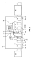
- said injection operation is carried out using an injection head (or nozzle) 11, which is arranged at a distance from the opening 4 of the container 1 to be treated and outside said container 1.
- the injection head 11 does not penetrate inside the cavity 3 of the container 1 during, or for the purposes of, said injection operation.
- said injection head 11 is thus advantageously arranged facing the opening 4 of the container 1, and above said opening 4, the container 1 being positioned vertically, with its bottom 7 oriented towards the ground.
- said injection operation is then carried out so as to inject said predetermined dose of treatment liquid according to a sufficiently narrow projection cone C, relative to the opening 4 of the container 1, so that substantially the entirety of said predetermined dose is found inside the cavity 3 of the container 1, at the end of said injection operation.
- said projection cone C therefore advantageously has a transverse section, included in a plane in which is inscribed the opening 4 of the container 1, which is of dimensions smaller than the respective dimensions of said opening 4 of the container 1 in said plane.
- the projection cone C generated by the injection head 11 can then advantageously present a (fictitious) base of smaller dimensions, and preferably much smaller, than the respective dimensions of the opening 4 of the container 1, such that the entire predetermined dose of treatment liquid (with possible inevitable losses, and although negligible, close) can be injected inside the cavity 3 of the container 1, and therefore substantially without any dispersion of treatment liquid next to the container 1 or on the exterior face 6 of the wall 2 and the ring 10 of the latter.
- projection cone is not to be considered, in the context of the invention, according to a strict mathematical definition of the term “ cone “, but that we preferentially mean “ projection cone ", a fictitious envelope (whether conical, frustoconical, or even ideally substantially cylindrical) inside which is contained substantially the entirety of the predetermined dose of treatment liquid projected by the injection head 11 in the direction of the cavity 3 of the container 1, as illustrated in dotted lines in the figure 1 .
- Said predetermined dose of treatment liquid advantageously corresponds to an also predetermined, known dose of treatment substance, insofar as the volume of the predetermined dose of treatment liquid projected by the injection head 11 d is known. on the one hand, and the concentration (mass or molar) of the treatment liquid in treatment substance on the other hand.
- the particular combination of the temperature characteristic of the interior face 5 of the wall 2 of the container 1 to be treated, on the one hand, and the above-mentioned preferential technical characteristics of the step of introducing the treatment liquid into the cavity 3 of the container 1 thus advantageously makes it possible to dealkalize in a particularly efficient manner borosilicate glass containers 1, whatever their size and capacity, and at very high rates when the process according to the invention is applied successively to a plurality of containers 1 in borosilicate glass. Indeed, it is not necessary to carry out cycles of insertion and withdrawal of the injection head 11 into, reciprocally out of, the cavity 3 of containers 1 to be treated, to treat a plurality of containers successively brought facing the injection head 11.
- the process according to the invention is particularly economical, clean and environmentally friendly, since it makes it possible to avoid an overdose of treatment substance and the unnecessary dispersion of a quantity of this treatment substance outside the container to be treated.
- the injection head 11 is not placed too close to the container 1 to be treated during the operation of injecting said predetermined dose of treatment liquid, in particular to avoid damage to the head injection head 11 under the effect of the heat emanating from the container 1.
- the injection head 11 is also not placed at too great a distance d from the opening 4 of the container 1, in particular in order not to degrade the precision of the injection operation and to facilitate its practical implementation.
- the injection head 11 may be advantageously arranged substantially opposite the opening 4 of the container 1 (as envisaged above) and at a distance d preferably between 1 cm and 20 cm, and more preferably still between 1 cm and 5 cm, from said opening 4 during the injection step.
- This distance d is preferably understood here as the average distance measured in a straight line between, on the one hand, the outlet opening 12 of the injection head 11 (through which the predetermined dose of treatment liquid leaves the head injection 11) and a plane containing the opening 4 of the container 1, as illustrated in figure 1 .
- the cone C for projecting said predetermined dose of liquid treatment is formed, by the injection head 4, so as to preferably present an apex angle ⁇ (or opening angle) substantially between 0° and 5°.
- the apex angle ⁇ of the projection cone is substantially between 0° and 1°, so that the predetermined dose of treatment liquid is advantageously injected into the cavity 3 of the container 1 according to an envelope fictitious cylindrical or quasi-cylindrical.
- the predetermined dose of treatment liquid is presented, for example, in the form of a plurality of droplets of treatment liquid, more or less distinct from each other, the latter can then form, between the injection head 11 and the cavity 3 of the container 1, a net or a substantially rectilinear jet of treatment liquid.
- the volume of the predetermined dose of treatment liquid injected by the injection head 11 is chosen substantially between 5 ⁇ L and 50 ⁇ L, and preferably between 5 ⁇ L and 30 ⁇ L, which advantageously makes it possible to limit the risk of damage to the container 1 by thermal shock, when the treatment liquid comes into contact with the hot interior face 5 of the wall 2 of the container 1.
- the choice of such a restricted volume of treatment liquid contributes to facilitating the injection of the entire predetermined dose of treatment substance into the cavity 3 of the containers 1 to be treated , and this even at very high rates, in the case where the head is preferably arranged at a distance from the opening 4 of the container 1 to be treated and outside the latter during the injection operation.
- the treatment liquid has a predefined concentration of said treatment substance in solution which is close (if not equal) to or just below the saturation concentration.
- the treatment liquid contains said treatment substance, which is substantially completely dissolved in a liquid, and preferably a volatile liquid as mentioned above, in an amount close to or just below the maximum amount which can be dissolved in the liquid considered for a chosen temperature of implementation of the treatment liquid.
- the predefined concentration thus advantageously corresponds to a concentration of treatment substance as high as possible, without exceeding the saturation concentration.
- the predefined concentration is thus substantially between approximately 70% and 100% of the saturation concentration, preferably between approximately 80% and 100% of the saturation concentration, more preferably between approximately 90% and 100% of the saturation concentration. the saturation concentration for a chosen operating temperature of the treatment liquid.
- the fact to maintain a concentration of treatment substance less than or equal to the saturation concentration advantageously makes it possible to guarantee excellent reproducibility of the quantity of treatment substance introduced into the container 1, and to further limit the risk of clogging of the head.
- the treatment liquid comprises an ammonium sulfate (treatment substance) dissolved in water (volatile liquid)
- the predefined concentration of the ammonium sulfate treatment liquid can generally be between approximately 0.1 g/mL and approximately 1 g/mL, depending in particular on the temperature at which the treatment liquid is used and the desired level of hydrolytic resistance.
- the predefined concentration of the dissolved ammonium sulfate treatment liquid is between about 0.5 g/mL and about 0.8 g/mL for a temperature of the treatment liquid between approximately 0°C and approximately 40°C, and preferably between approximately 10°C and approximately 40°C.
- the preset concentration of dissolved ammonium sulfate treatment liquid could go up to approximately 1 g / mL for a treatment liquid temperature of approximately 90°C.
- the injection operation of the method according to the invention is advantageously carried out while the container 1 to be treated is moving relative to the injection head 11, preferably at a speed of at least 25 m per minute, more preferably at least 30 m per minute , and more preferably up to 40 m per minute, in particular so as to be able to process using the injection head 11 a plurality of containers 1 at a particularly high rate.
- the injection head 11 moves, during the injection operation, relative to the container 1 to be treated, which is kept stationary (in the terrestrial reference frame).
- the injection head 11 is on the contrary kept stationary (in the terrestrial reference frame), while the container 1 to be treated moves relative to the injection head 11, for example on a conveyor positioned below and opposite the injection head 11.
- the method according to the invention preferably comprises a step detecting the presence of the container 1 upstream of the injection head 11 (taking into consideration the direction of relative movement of the injection head 11 and the container 1), prior to the injection operation, to synchronize the triggering of the injection operation with the arrival of the container 1 at the level of the injection head 11, and preferably opposite the outlet opening 12 of the latter.
- the step of introducing the treatment liquid inside the receiving cavity 3 of the container 1 may comprise a plurality of successive injection operations of said predetermined dose of treatment liquid. Indeed, it may be necessary, depending on the dimensions of the glass container 1 to be treated, to use a significant quantity of treatment substance to achieve the desired level of dealkalization, without having to resort to predetermined doses for this. of treatment liquid in large volumes, which could cause a high risk of thermal shock detrimental to the mechanical resistance of the container 1.
- the process according to the invention preferably comprises, prior to the step of introducing the treatment liquid to the inside the cavity 3 of the container 1, an operation of regulation and control of the temperature of the treatment liquid to ensure that it remains substantially constant over time, and advantageously equal to a predefined set temperature.
- the treatment liquid, and preferably said predetermined dose of the latter is injected into the cavity 3 of the container 1 at an advantageously predefined temperature, which is then substantially identical for each container 1 to be treated according to the method of the invention.
- the method according to the invention may comprise, prior to the step of introducing the treatment liquid inside the cavity 3 of the container 1, an operation of preheating the treatment liquid (typically at a temperature higher than ambient temperature), so as to reduce the difference between the temperature of the treatment liquid, and preferably of said predetermined dose of the latter, injected during the injection operation, and the temperature of the interior face 5 of the wall 2 of the container 1 to be treated.
- preheating the treatment liquid typically at a temperature higher than ambient temperature
- the method according to the invention may advantageously comprise, after the step of introducing the treatment liquid into its cavity 3, a step of transmitting the container 1 thus treated to a device for annealing glass containers, such as an arch conventional industrial annealing, with a view to advantageously subjecting the treated container 1 to an annealing step.
- an installation 13 for processing a glass container 1, for implementing the method according to the invention described in detail above It is thus advantageously an installation 13 for dealkalizing the interior face 5 of the wall 2 of such a container 1 in borosilicate glass, which wall 2 delimits a reception cavity 3 for a product and an opening 4 giving access to said reception cavity 3.
- the description set out in the above in relation to the method according to the invention remains valid and applicable, mutatis mutandis, to the present installation 13, and vice versa.
- This is preferably an industrial installation, advantageously automated.
- said installation 13 is designed to process a large number of containers 1 in a substantially uninterrupted manner.
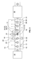
- a preferred embodiment of the installation 13 is illustrated by example, schematically, in figures 2 And 3 .
- the installation 13 comprises a means 14 for supplying a container 1 made of borosilicate glass, as described above, of which (at least) the interior face 5 of the wall 2 is at a temperature of at least 350°C , preferably between 350°C and 850°C, preferably between 350°C and 800°C, preferably between 350°C and 700°C, preferably between 500°C and 700°C, and preferably again between 500°C and 650°C.
- this means of supply comprises a heating means, of any known suitable type (and for example, of the arch or oven type), designed to heat a pre-existing borosilicate glass container, conforming to the description above, and whose interior face of the wall is initially at a temperature close to (if not equal to) ambient temperature, so that the temperature of at least the interior face of the wall of the container reaches a value of at least 350 °C, preferably between 350°C and 850°C, preferably between 350°C and 800°C, preferably between 350°C and 700°C, preferably between 500°C and 700°C , and preferably still between 500°C and 650°C.
- the means 14 for supplying the container 1 comprises a system 15 for collecting a container 1 made of borosilicate glass, conforming to the description above, at the outlet of a hot forming machine 16 of a glass container from a glass blank, while said container 1 is still sufficiently hot so that (at least) the interior face 5 of the wall 2 of said container 1 is at a temperature of at least 350 °C, preferably between 350°C and 850°C, preferably between 350°C and 800°C, preferably between 350°C and 700°C, preferably between 500°C and 700°C , and preferably still between 500°C and 650°C.
- the installation 13 according to the invention therefore advantageously does not comprise any specific heating means for heating the container 1, the interior face 5 of the wall 2 of the container 1 being brought to a temperature of at least 350 °C, preferably between 350°C and 850°C, preferably between 350°C and 800°C, preferably between 350°C and 700°C, preferably between 500°C and 700°C , preferably still between 500°C and 650°C, as a direct result of a prior forming operation of said container 1 by said forming machine 16.
- this machine or forming installation 16 for borosilicate glass containers can be of any known type of forming, such as for example an IS machine in the case of a container made of molded glass.
- the collection system 15 can, for example, comprise an advantageously robotic arm and/or a conveyor 17 (for example belt or roller), designed(es), arranged(s) and dimensioned(s) to collect a container 1 glass at the outlet of a forming machine 16, sufficiently close to the latter so that (at least) the interior face 5 of the wall 2 of the container 1 is still at a temperature of at least 350 ° C, of preferably between 350°C and 850°C, preferably between 350°C and 800°C, preferably between 350°C and 700°C, preferably between 500°C and 700°C, and preferably still between 500°C and 650°C.
- the installation 13 also includes a means (or station) for introducing 18 inside the receiving cavity 3 of the container 1 to be treated, while the interior face 5 of the wall 2 of the latter is at a temperature at least 350°C, preferably between 350°C and 850°C, preferably between 350°C and 800°C, preferably between 350°C and 700°C, preferably between 500°C C and 700°C, and preferably still between 500°C and 650°C, of a treatment liquid containing a treatment substance (or dealkalization substance) designed to react under the effect of the heat of the face interior 5 of the wall 2 of the container 1 to cause a dealkalization of the glass, typically in the vicinity of the surface of the interior face 5 of the wall 2.
- a treatment substance or dealkalization substance
- the means 18 for introducing the treatment liquid comprises at least one injection head (or nozzle or valve) 11 designed to be arranged (and maintained) at a distance from the opening 4 of the container 1 and outside of the latter, and to inject (while the injection head 11 is thus arranged) a predetermined dose of the treatment liquid, preferably according to a projection cone C sufficiently narrow relative to the opening 4 of the container 1 so that substantially the entirety of said predetermined dose is found inside the cavity 3 of the container 1.
- the introduction means 18 is then advantageously designed and configured to maintain the injection head 11 so that the latter does not penetrate inside the cavity 3 of the container 1 when the injection head 11 is in operation and injects said predetermined dose of treatment liquid into the cavity 3 of the container 1.
- the injection head 11 is as to it designed to generate, at an outlet orifice (opening) 12, said predetermined dose of treatment liquid and inject it, project it, according to a projection cone C having a (fictitious) base of lower dimensions, and preferably much smaller than the respective dimensions of the opening 4 of the container 1, as shown in figure 1 and described previously in connection with the process according to the invention.
- the installation 13 advantageously suitable for carry out a particularly effective dealkalization treatment of glass containers 1, whatever their size and capacity, and this at very high rates when the installation is used to successively treat a plurality of glass containers 1.
- the installation 13 is particularly economical, clean and environmentally friendly, since it makes it possible to avoid an overdose of treatment substance and the unnecessary dispersion of a quantity of this treatment substance outside the container to be treated. .
- the supply means 14 of the glass container 1 to be treated is designed to bring the container 1 to the introduction means 18 so that the container 1 is positioned vertically, with its bottom 7 oriented towards the ground, and the means introduction 18 is designed so that the injection head 11 can be arranged facing the opening 4 of the container 1, and above said opening 4.
- the introduction means 18 may comprise a support adjustable, so as to adapt, preferably automatically, the position (or altitude) of the injection head 11 according to the dimensions of the container(s) 1 to be treated.
- the introduction means 18 is designed to arrange and, more preferably maintain, the injection head 11 substantially facing the opening 4 of the container 1 and at a distance d of between 1 cm and 20 cm, and preferably between 1 cm and 5 cm, from said opening 4, when the injection head 11 is in operation, that is to say say when it forms the predetermined dose and projects it towards the cavity 3 of the container 1.
- This distance d is preferably understood here also to be the average distance measured in a straight line between, on the one hand, the opening of outlet 12 of the injection head 11 and a plane containing the opening 4 of the container 1, as illustrated in figure 1 .
- the injection head 11 is designed to generate a projection cone C of said predetermined dose of treatment liquid having an apex angle ⁇ substantially between 0° and 5°. Even more preferably, the injection head 11 is designed to generate a projection cone C of said predetermined dose of treatment liquid having an angle ⁇ substantially between 0° and 1°, so that the predetermined dose of liquid treatment can advantageously be injected into the cavity 3 of the container 1 according to a fictitious envelope which is substantially cylindrical or quasi-cylindrical.
- the injection head 11 is preferably designed so that the volume of said predetermined dose of said treatment liquid injected is between 5 ⁇ L and 50 ⁇ L, and preferably between 5 ⁇ L and 30 ⁇ L.
- the injection head 11 comprises an electromechanical actuator driven by a piezoelectric device, to allow the dosing and injection of liquid volumes of between 5 ⁇ L and 50 ⁇ L, and preferably between 5 ⁇ L and 30 ⁇ L, in response to an electrical control signal.
- the injection head 11 may comprise, for example, an electromechanical actuator driven by a solenoid device(s).
- the installation 13 may be of interest for the treatment of a container 1 which remains immobile relative to the injection head 11 during the operation of the latter, the installation 13 is preferably designed to allow a dealkalization treatment of one or more glass containers 1 in movement by supply to the injection head 11, preferably at a speed of at least 25 m per minute, more preferably at least 30 m per minute, and more preferably up to 40m per minute, in particular so as to be able to process using the injection head 11 a plurality of containers 1 at a particularly high rate.
- the installation 13 comprises, on the one hand, means for moving the injection head 11 during its operation, preferably at the speed mentioned above, relative to the container 1 which remains immobile (in the terrestrial frame of reference).
- the installation 13 preferably comprises a conveyor 19 (for example belt or roller), or any other suitable known means, designed to, capable of, put the container(s) 1 to be treated in movement relative to the injection head 11, which is kept stationary (in the terrestrial reference frame, for example by means of a frame fixed to the ground), preferably at a speed of at least 25 m per minute, more preferably d at least 30 m per minute, and preferably up to 40 m per minute.
- a conveyor 19 for example belt or roller
- any other suitable known means designed to, capable of, put the container(s) 1 to be treated in movement relative to the injection head 11, which is kept stationary (in the terrestrial reference frame, for example by means of a frame fixed to the ground), preferably at a speed of at least 25 m per minute, more preferably d at least 30 m per minute, and preferably up to 40 m per minute.
- the conveyor 19 can then be preferably positioned below and opposite the injection head 11, the container 1 being able to be positioned vertically, with its bottom 7 resting on the conveyor 19 and its opening 4 oriented upwards, from so that said opening 4 is positioned below (and preferably directly above) the outlet opening 12 of the injection head 11.
- the conveyor 19 could be the same as the conveyor 17 that comprises, according to the example proposed above, the collection system 15 of the glass container 1 at the outlet of a forming machine 16.
- the installation 13 comprises a means 20 for detecting the presence of the container 1 upstream of the injection head 1, and a control unit 21 connected, mechanically or electrically, on the one hand to the detection means 20 and on the other hand to the injection head 11, to synchronize the triggering of the operation of the injection head 11 with the arrival of the container 1 at the level of the injection head 11, and preferably opposite the outlet opening 12 of the latter, as envisaged above in connection with the method according to the invention.
- the detection means 20 can be of the optical barrier type and comprise either a light beam emitter (for example infrared) positioned opposite a photoelectric cell, or a detection cell 22 comprising both a beam emitter light (for example infrared) and a photoelectric cell and a light reflector 23 positioned opposite a photoelectric cell, as in the example illustrated in Figure 3 .
- the detection cell 22 and the reflector 23 are advantageously positioned on either side of the movement trajectory of the container 1, at a known distance from the injection head 11. In the absence of container 1, the detection cell detection 22 emits a light beam (shown in dotted lines at the Figure 3 ) which is reflected by the reflector 23 and detected by the photoelectric cell of the detection cell 22.
- control unit 21 controls the stopping of the operation of the injection head 11.
- the light beam is interrupted (or at least disturbed) by the container 1, so that the photoelectric cell does not detect a light beam (or detects a disturbed light beam), which indicates the presence of a container 1
- the control unit 21 controls, with a time delay defined according to the known speed of movement of the container 1, the triggering of the operation of the injection head 11.
- such a detection means 20 optical barrier type will be designed and arranged in such a way that the light beam emitted is interrupted by the neck 9 or the ring 10 of a container 1, and not by the body of the latter, so as to allow finer synchronization of operation of the injection head 11, and therefore a more precise injection of the predetermined dose of treatment liquid into the cavity 3 of the container 1, when the latter arrives at the level of the injection head 11.
- other known and adequate means of detection not necessarily optical, could be considered.
- the means 18 for introducing the treatment liquid may comprise a plurality of injection heads 11, or a single injection head 11 provided with a plurality of outlet openings 12, in order to allow the injection of 'a predetermined dose of treatment liquid simultaneously in the cavity 3 of a plurality of glass containers 1 (whether or not the latter are then in movement relative to the injection heads 11), and/or allow the injection successive doses of several predetermined doses of treatment liquid in the cavity 3 of the same container 1.
- the introduction means 18 can then comprise, for example, a plurality of distinct injection heads 11, mounted one in a row on the other according to the trajectory of relative movement of the injection heads and the container(s) 1.
- the introduction means 18 may comprise a plurality of distinct injection heads 11 mounted next to each other in a direction transverse to the relative movement trajectory of the injection heads and the container(s) 1, so as to allow the treatment of glass containers 1 arranged in rows.
- the installation 13 advantageously comprises, when it is intended to successively or simultaneously treat a plurality of containers 1 in glass, a means of controlling the relative position and aligning the containers, upstream of the injection head(s) 11, so as to further improve the precision of the injection of the predetermined dose of liquid treatment inside the cavity 3 of the containers 1 to be treated.
- a means of controlling the relative position and aligning the containers are known as such in the field of glass container processing, so that it is not necessary to describe them here in more detail.
- the installation 13 comprises a system for preparing and/or storing the treatment liquid, upstream of the injection head 11 of the introduction means 18.
- This preparation and/or storage system 24 can advantageously understand, a system for mixing the treatment substance and the volatile liquid, to obtain and/or maintain a perfectly homogeneous treatment liquid.
- the installation 13 preferably comprises, and for example at the system level, mentioned above, preparation and / or storage 24 of the treatment liquid, a thermal regulation system 26 to maintain the treatment liquid at a constant predefined temperature before the latter is injected into the cavity 3 of the container 1 by the injection head 11.
- the introduction means 18 may comprise, and for example at said system for preparing and/or storing the treatment liquid 24, a system for pressurizing the treatment liquid upstream of or in the injection head 11 , for example at a relative pressure of between 0.5 bar and 4 bar.
- the installation 13 may advantageously comprise, downstream of the means 18 for introducing the treatment liquid into the cavity 3 of the container 1, and preferably above the opening 4 of the container 1, one or more hoods 28 of extraction for effectively vacuum and evacuate gas emissions resulting from the glass dealkalization reaction.
- the installation 13 may advantageously comprise, downstream of the means 18 for introducing the treatment liquid into the cavity 3 of the container 1, a means 29 for transmitting the treated container 1 to the inlet of a container annealing device 30 glass, such as a conventional industrial annealing arch 30.
- the transmission means 29 may, for example, comprise an advantageously robotic arm and/or a conveyor 31 (for example belt or roller), designed, arranged and dimensioned to collect the container 1 in treated glass at the level, or downstream, of the introduction means 18 and bring it to the inlet of the annealing device 30.
- a conveyor 31 for example belt or roller
- the process according to the invention and the installation for its implementation described above can be advantageously integrated directly into processes and production lines.
- industrial manufacturing of borosilicate glass containers the installation in question being able to be positioned in a manufacturing line, between a machine for forming borosilicate glass containers and a device for annealing the latter.
- the process according to the invention and the installation for its implementation described above allow the dealkalization of the interior face of the wall of a large number of borosilicate glass containers, at a rate which can be greater than 400 vials/minute in a single row (a single injection head) or 800 vials/minute in a double row (two parallel rows of containers on the conveyor, two injection heads), in particular for containers with a capacity nominal from 5 mL to 50 mL, while achieving a level of hydrolytic resistance of the treated containers better than that usually achieved using known processes and installations for dealkalization with a solid or gaseous treatment substance.
- the invention finds its application in the field of processes for treating glass containers, and more precisely in the technical field of processes for dealkalizing the interior wall of glass containers, such as containers forming primary glass packaging for use. pharmaceuticals.
Landscapes
- Chemical & Material Sciences (AREA)
- Materials Engineering (AREA)
- Engineering & Computer Science (AREA)
- Chemical Kinetics & Catalysis (AREA)
- General Chemical & Material Sciences (AREA)
- Geochemistry & Mineralogy (AREA)
- Life Sciences & Earth Sciences (AREA)
- Organic Chemistry (AREA)
- Physics & Mathematics (AREA)
- Thermal Sciences (AREA)
- Surface Treatment Of Glass (AREA)
- Medical Preparation Storing Or Oral Administration Devices (AREA)
- Silicon Compounds (AREA)
Applications Claiming Priority (3)
| Application Number | Priority Date | Filing Date | Title |
|---|---|---|---|
| FR1907826A FR3098512B1 (fr) | 2019-07-11 | 2019-07-11 | Procede et installation de desalcalinisation de recipients en verre par voie liquide |
| PCT/FR2020/051255 WO2021005318A1 (fr) | 2019-07-11 | 2020-07-10 | Procede de desalcalinisation de recipients en verre borosilicate par voie liquide |
| EP20753396.9A EP3997044B1 (de) | 2019-07-11 | 2020-07-10 | Verfahren zur entalkalisierung von borosilikatglasbehältern mittels flüssigkeit |
Related Parent Applications (3)
| Application Number | Title | Priority Date | Filing Date |
|---|---|---|---|
| PCT/FR2020/051255 Previously-Filed-Application WO2021005318A1 (fr) | 2019-07-11 | 2020-07-10 | Procede de desalcalinisation de recipients en verre borosilicate par voie liquide |
| EP20753396.9A Division-Into EP3997044B1 (de) | 2019-07-11 | 2020-07-10 | Verfahren zur entalkalisierung von borosilikatglasbehältern mittels flüssigkeit |
| EP20753396.9A Division EP3997044B1 (de) | 2019-07-11 | 2020-07-10 | Verfahren zur entalkalisierung von borosilikatglasbehältern mittels flüssigkeit |
Publications (2)
| Publication Number | Publication Date |
|---|---|
| EP4279462A2 true EP4279462A2 (de) | 2023-11-22 |
| EP4279462A3 EP4279462A3 (de) | 2024-01-10 |
Family
ID=68501751
Family Applications (4)
| Application Number | Title | Priority Date | Filing Date |
|---|---|---|---|
| EP20753396.9A Active EP3997044B1 (de) | 2019-07-11 | 2020-07-10 | Verfahren zur entalkalisierung von borosilikatglasbehältern mittels flüssigkeit |
| EP23177046.2A Pending EP4279462A3 (de) | 2019-07-11 | 2020-07-10 | Verfahren zur entalkalisierung von borosilikatglasbehältern mittels flüssigkeit |
| EP23160477.8A Pending EP4234509A3 (de) | 2019-07-11 | 2020-07-10 | Verfahren und anlage zum entalkalisieren von glasbehältern mittels flüssigkeit |
| EP20753395.1A Active EP3997043B1 (de) | 2019-07-11 | 2020-07-10 | Verfahren und anlage zum entalkalisieren von glasbehältern mittels flüssigkeit |
Family Applications Before (1)
| Application Number | Title | Priority Date | Filing Date |
|---|---|---|---|
| EP20753396.9A Active EP3997044B1 (de) | 2019-07-11 | 2020-07-10 | Verfahren zur entalkalisierung von borosilikatglasbehältern mittels flüssigkeit |
Family Applications After (2)
| Application Number | Title | Priority Date | Filing Date |
|---|---|---|---|
| EP23160477.8A Pending EP4234509A3 (de) | 2019-07-11 | 2020-07-10 | Verfahren und anlage zum entalkalisieren von glasbehältern mittels flüssigkeit |
| EP20753395.1A Active EP3997043B1 (de) | 2019-07-11 | 2020-07-10 | Verfahren und anlage zum entalkalisieren von glasbehältern mittels flüssigkeit |
Country Status (9)
| Country | Link |
|---|---|
| US (2) | US12209050B2 (de) |
| EP (4) | EP3997044B1 (de) |
| CN (2) | CN114096494A (de) |
| AT (1) | AT18136U1 (de) |
| BR (2) | BR112022000288A2 (de) |
| ES (2) | ES2962923T3 (de) |
| FR (1) | FR3098512B1 (de) |
| PL (2) | PL3997043T3 (de) |
| WO (2) | WO2021005317A1 (de) |
Families Citing this family (3)
| Publication number | Priority date | Publication date | Assignee | Title |
|---|---|---|---|---|
| FR3098512B1 (fr) | 2019-07-11 | 2022-08-26 | Sgd Sa | Procede et installation de desalcalinisation de recipients en verre par voie liquide |
| FR3105932B1 (fr) * | 2020-01-08 | 2021-12-17 | Sgd Sa | Procede de traitement de recipients en verre comprenant un controle optique d’une quantite de substance de traitement distribuee et installation de traitement afferente |
| CN115157913A (zh) * | 2022-06-30 | 2022-10-11 | 重庆昊晟玻璃股份有限公司 | 一种玻璃瓶瓶底描金工艺 |
Family Cites Families (31)
| Publication number | Priority date | Publication date | Assignee | Title |
|---|---|---|---|---|
| CA773057A (en) | 1967-12-05 | J. Hazdra James | Method of increasing the durability of glassware | |
| US2033076A (en) * | 1934-06-01 | 1936-03-03 | Hartford Empire Co | Method of and apparatus for forming hollow glass articles |
| GB531145A (en) * | 1939-07-13 | 1940-12-30 | United Glass Bottle Mfg Ltd | Improvements in or relating to methods and means for improving the durability of glass containers |
| GB563091A (en) | 1943-01-25 | 1944-07-28 | United Glass Bottle Mfg Ltd | Improvements in or relating to means or apparatus for improving the durability of glass containers |
| US2947117A (en) | 1955-10-13 | 1960-08-02 | Owens Illinois Glass Co | Apparatus and method for treating interior surfaces of glass containers |
| DE1073160B (de) | 1956-05-31 | 1960-01-14 | Owens Illinois Glass Company Toledo Ohio (V St A) | Vorrich tung zum Behandeln der Innenflachen von Glasampullen od a enghalsigen Glasbehaltern |
| FR1235994A (fr) | 1959-05-30 | 1960-07-15 | Saint Gobain | Procédé pour l'obtention de verres pauvres en alcali |
| BE618737A (de) | 1961-06-12 | |||
| US3348934A (en) | 1964-12-23 | 1967-10-24 | Owens Illinois Inc | Method of treating the surfaces of glass containers |
| US3281225A (en) * | 1965-09-30 | 1966-10-25 | Brockway Glass Co Inc | Method of increasing the durability of glassware |
| US3687651A (en) | 1968-12-26 | 1972-08-29 | Ball Brothers Co Inc | Ignition flash control means for bottle treatment |
| JPS6022662B2 (ja) | 1978-10-20 | 1985-06-03 | 石塚硝子株式会社 | 安定した化学的耐久性・機械的強度を有する軽量びんの製造方法 |
| JPS5864248A (ja) | 1981-10-13 | 1983-04-16 | Nippon Taisanbin Kogyo Kk | ガラスびんの表面処理方法 |
| FR2619101A1 (fr) * | 1987-08-05 | 1989-02-10 | Saint Gobain Vitrage | Technique de production de microspheres en silice |
| SU1564132A1 (ru) | 1988-04-25 | 1990-05-15 | Львовский политехнический институт им.Ленинского комсомола | Способ термохимической обработки полых стеклоизделий |
| FR2697014B1 (fr) | 1992-10-19 | 1995-01-20 | Souchon Neuvesel Verreries | Procédé de revêtement d'un substrat en matériau vitreux, par un film de silice. |
| FR2700764B1 (fr) * | 1993-01-26 | 1995-04-14 | Lalique | Procédé pour le traitement de surface d'articles en verre, notamment en cristal et articles ainsi obtenus. |
| FR2744440B1 (fr) * | 1996-02-07 | 1998-03-20 | Saint Gobain Vitrage | Procede de traitement de substrats en verre |
| KR100628780B1 (ko) | 1998-04-17 | 2006-09-29 | 도요 세이칸 가부시키가이샤 | 양압 포장체의 제조방법 및 그 장치 |
| US6982006B1 (en) * | 1999-10-19 | 2006-01-03 | Boyers David G | Method and apparatus for treating a substrate with an ozone-solvent solution |
| JP2001294447A (ja) * | 2000-04-12 | 2001-10-23 | Nippon Electric Glass Co Ltd | ガラス容器およびその処理方法 |
| AT6868U1 (de) | 2003-06-17 | 2004-05-25 | Stoelzle Oberglas Ag & Co Kg | Verfahren und vorrichtung zur behandlung von ware, beispielsweise hohlware aus glas |
| FI20090057A0 (fi) * | 2009-02-17 | 2009-02-17 | Beneq Oy | Antibakteerinen lasi |
| CN102320759A (zh) | 2011-06-23 | 2012-01-18 | 宁波正力药品包装有限公司 | 一种医药包装用玻璃瓶的脱碱工艺 |
| DE102014101756B4 (de) | 2014-02-12 | 2016-01-21 | Schott Ag | Verfahren zur Herstellung von Glasrohren mit einer verbesserten chemischen Beständigkeit sowie Verwendung hiervon |
| DE112015002174T5 (de) | 2014-05-09 | 2017-02-09 | Wab Srl | Verfahren zum Beschichten einer Innenwand eines Behälters |
| DE102016200223B4 (de) * | 2016-01-12 | 2019-03-07 | Schott Ag | Verfahren und Vorrichtung zur Silikonisierung der Innenfläche von Hohlkörpern |
| CN207188400U (zh) | 2017-05-25 | 2018-04-06 | 沧州四星玻璃股份有限公司 | 一种用于安瓿瓶的喷液装置 |
| US11034613B2 (en) * | 2017-11-21 | 2021-06-15 | Corning Incorporated | Methods for ion exchanging glass articles |
| FR3078329B1 (fr) | 2018-02-27 | 2022-09-30 | Sgd Sa | Procede de traitement d'un recipient a paroi en verre et installation afferente |
| FR3098512B1 (fr) | 2019-07-11 | 2022-08-26 | Sgd Sa | Procede et installation de desalcalinisation de recipients en verre par voie liquide |
-
2019
- 2019-07-11 FR FR1907826A patent/FR3098512B1/fr active Active
-
2020
- 2020-07-10 PL PL20753395.1T patent/PL3997043T3/pl unknown
- 2020-07-10 US US17/624,944 patent/US12209050B2/en active Active
- 2020-07-10 EP EP20753396.9A patent/EP3997044B1/de active Active
- 2020-07-10 WO PCT/FR2020/051251 patent/WO2021005317A1/fr not_active Ceased
- 2020-07-10 CN CN202080050619.7A patent/CN114096494A/zh active Pending
- 2020-07-10 ES ES20753396T patent/ES2962923T3/es active Active
- 2020-07-10 EP EP23177046.2A patent/EP4279462A3/de active Pending
- 2020-07-10 US US17/624,773 patent/US12479762B2/en active Active
- 2020-07-10 EP EP23160477.8A patent/EP4234509A3/de active Pending
- 2020-07-10 CN CN202080050622.9A patent/CN114096495A/zh active Pending
- 2020-07-10 BR BR112022000288A patent/BR112022000288A2/pt unknown
- 2020-07-10 PL PL20753396.9T patent/PL3997044T3/pl unknown
- 2020-07-10 WO PCT/FR2020/051255 patent/WO2021005318A1/fr not_active Ceased
- 2020-07-10 BR BR112022000287A patent/BR112022000287A2/pt unknown
- 2020-07-10 AT ATGM50031/2023U patent/AT18136U1/de unknown
- 2020-07-10 EP EP20753395.1A patent/EP3997043B1/de active Active
- 2020-07-10 ES ES20753395T patent/ES2951179T3/es active Active
Also Published As
| Publication number | Publication date |
|---|---|
| EP3997044B1 (de) | 2023-08-09 |
| US20220267203A1 (en) | 2022-08-25 |
| EP3997044A1 (de) | 2022-05-18 |
| US12479762B2 (en) | 2025-11-25 |
| AT18136U1 (de) | 2024-02-15 |
| CN114096494A (zh) | 2022-02-25 |
| EP4234509A3 (de) | 2024-01-10 |
| US20220242784A1 (en) | 2022-08-04 |
| PL3997044T3 (pl) | 2024-04-08 |
| EP4279462A3 (de) | 2024-01-10 |
| EP3997043B1 (de) | 2023-04-19 |
| EP4234509A2 (de) | 2023-08-30 |
| ES2962923T3 (es) | 2024-03-21 |
| FR3098512A1 (fr) | 2021-01-15 |
| BR112022000288A2 (pt) | 2022-02-22 |
| WO2021005318A1 (fr) | 2021-01-14 |
| PL3997043T3 (pl) | 2023-08-21 |
| WO2021005317A1 (fr) | 2021-01-14 |
| FR3098512B1 (fr) | 2022-08-26 |
| US12209050B2 (en) | 2025-01-28 |
| ES2951179T3 (es) | 2023-10-18 |
| BR112022000287A2 (pt) | 2022-02-22 |
| EP3997043A1 (de) | 2022-05-18 |
| CN114096495A (zh) | 2022-02-25 |
Similar Documents
| Publication | Publication Date | Title |
|---|---|---|
| EP3997044B1 (de) | Verfahren zur entalkalisierung von borosilikatglasbehältern mittels flüssigkeit | |
| FR3052161A1 (fr) | Procede de formation d'un revetement barriere a la surface d'un recipient et installation afferente | |
| EP0191258A1 (de) | Verfahren und Vorrichtung zum Dosieren von rieselfähigen Substanzen | |
| EP1307298A1 (de) | Durch plasma abgeschiedene sperrbeschichtung mit einer grenzflächenschicht, verfahren zur herstellung derselben und so beschichteten behälter | |
| EP3074313B1 (de) | Vorrichtung und verfahren zur aseptischen füllung | |
| WO2019166719A1 (fr) | Procede de traitement d'un recipient a paroi en verre et installation afferente | |
| WO2018083419A1 (fr) | Dispositif et procede de conditionnement en pression d'un contenant a traiter et machine de conditionnement en pression associee | |
| FR3017613A1 (fr) | Procede et dispositif de passivation de la surface interne d'un flacon en verre et flacon obtenu avec un tel procede. | |
| EP4069652A1 (de) | Anlage zur behandlung von glasbehältern mit einer kammer zur dosierung einer behandlungssubstanz mit doppelblende und zugehöriges verfahren | |
| EP4087826A1 (de) | Verfahren zur behandlung von glasbehältern mit einer optischen kontrolle einer menge einer abgegebenen behandlungssubstanz und zugehörige behandlungseinrichtung | |
| EP3535189B1 (de) | Verfahren und vorrichtung zur druckverpackung eines aufzubereitenden behälters und zugehörige druckverpackungsmaschine | |
| EP0179678B1 (de) | Verfahren und Gerät zum Übertragen und Dosieren spröder Teilchen mit hohem Rhythmus z.B. zum Einbringen in einen Behälter | |
| EP2786102B1 (de) | Vorrichtung zur abgabe eines pulvers, kappe für eine solche vorrichtung und arbeitsplatz mit einer derartigen vorrichtung | |
| FR2510749A1 (fr) | Procede et dispositif permettant de prelever un liquide stocke dans un recipient reservoir et d'en delivrer une quantite determinee en vue de son utilisation et installation de dosage equipee d'un tel dispositif | |
| FR2666299A1 (fr) | Installation de sterilisation de recipients a l'aide de peroxyde d'hydrogene et procede d'utilisation. | |
| FR3118771A1 (fr) | Recipient en verre borosilicate a resistance chimique amelioree pour substance pharmaceutique ou de diagnostic | |
| EP0543722A1 (de) | Verfahren und Vorrichtung zum Messen der Laccase-Aktivität in Mosten mit Hilfe des Syringaldazine-Tests | |
| FR3028778A1 (fr) | Procede de fabrication d'une couche de revetement de la face interne d'un recipient et recipient obtenu avec un tel procede | |
| FR3111131A3 (fr) | Dispositif de dosage de liqueur dans une bouteille | |
| FR3118770A1 (fr) | Recipient en verre sodocalcique a resistance chimique amelioree pour substance pharmaceutique ou de diagnostic | |
| WO1998032671A1 (fr) | Flacon en verre pour reactif utilisable par un automate d'analyse |
Legal Events
| Date | Code | Title | Description |
|---|---|---|---|
| PUAI | Public reference made under article 153(3) epc to a published international application that has entered the european phase |
Free format text: ORIGINAL CODE: 0009012 |
|
| STAA | Information on the status of an ep patent application or granted ep patent |
Free format text: STATUS: THE APPLICATION HAS BEEN PUBLISHED |
|
| AC | Divisional application: reference to earlier application |
Ref document number: 3997044 Country of ref document: EP Kind code of ref document: P |
|
| AK | Designated contracting states |
Kind code of ref document: A2 Designated state(s): AL AT BE BG CH CY CZ DE DK EE ES FI FR GB GR HR HU IE IS IT LI LT LU LV MC MK MT NL NO PL PT RO RS SE SI SK SM TR |
|
| PUAL | Search report despatched |
Free format text: ORIGINAL CODE: 0009013 |
|
| AK | Designated contracting states |
Kind code of ref document: A3 Designated state(s): AL AT BE BG CH CY CZ DE DK EE ES FI FR GB GR HR HU IE IS IT LI LT LU LV MC MK MT NL NO PL PT RO RS SE SI SK SM TR |
|
| RIC1 | Information provided on ipc code assigned before grant |
Ipc: C03C 23/00 20060101AFI20231206BHEP |
|
| STAA | Information on the status of an ep patent application or granted ep patent |
Free format text: STATUS: REQUEST FOR EXAMINATION WAS MADE |
|
| 17P | Request for examination filed |
Effective date: 20240704 |
|
| RBV | Designated contracting states (corrected) |
Designated state(s): AL AT BE BG CH CY CZ DE DK EE ES FI FR GB GR HR HU IE IS IT LI LT LU LV MC MK MT NL NO PL PT RO RS SE SI SK SM TR |