EP4276047A2 - Machine de construction - Google Patents
Machine de construction Download PDFInfo
- Publication number
- EP4276047A2 EP4276047A2 EP23199748.7A EP23199748A EP4276047A2 EP 4276047 A2 EP4276047 A2 EP 4276047A2 EP 23199748 A EP23199748 A EP 23199748A EP 4276047 A2 EP4276047 A2 EP 4276047A2
- Authority
- EP
- European Patent Office
- Prior art keywords
- control
- construction machine
- functional element
- detected
- machine according
- Prior art date
- Legal status (The legal status is an assumption and is not a legal conclusion. Google has not performed a legal analysis and makes no representation as to the accuracy of the status listed.)
- Pending
Links
- 238000010276 construction Methods 0.000 title claims abstract description 102
- 230000033001 locomotion Effects 0.000 claims abstract description 92
- 238000001514 detection method Methods 0.000 claims description 37
- 230000001133 acceleration Effects 0.000 claims description 28
- 239000000725 suspension Substances 0.000 claims description 10
- 238000003384 imaging method Methods 0.000 claims description 9
- 238000011156 evaluation Methods 0.000 claims description 7
- 238000006073 displacement reaction Methods 0.000 claims description 2
- 239000007787 solid Substances 0.000 claims description 2
- 239000011521 glass Substances 0.000 description 14
- 210000003414 extremity Anatomy 0.000 description 12
- 230000003287 optical effect Effects 0.000 description 8
- 210000004247 hand Anatomy 0.000 description 5
- 238000003825 pressing Methods 0.000 description 5
- 210000000245 forearm Anatomy 0.000 description 4
- 238000012544 monitoring process Methods 0.000 description 4
- 238000013461 design Methods 0.000 description 3
- 238000011161 development Methods 0.000 description 3
- 210000000707 wrist Anatomy 0.000 description 3
- 238000005452 bending Methods 0.000 description 2
- 238000006243 chemical reaction Methods 0.000 description 2
- 238000003032 molecular docking Methods 0.000 description 2
- 238000012806 monitoring device Methods 0.000 description 2
- 238000012545 processing Methods 0.000 description 2
- 230000003190 augmentative effect Effects 0.000 description 1
- 230000002457 bidirectional effect Effects 0.000 description 1
- 230000005540 biological transmission Effects 0.000 description 1
- 238000004891 communication Methods 0.000 description 1
- 238000013499 data model Methods 0.000 description 1
- 230000001419 dependent effect Effects 0.000 description 1
- 230000000694 effects Effects 0.000 description 1
- 230000005057 finger movement Effects 0.000 description 1
- 210000003128 head Anatomy 0.000 description 1
- 230000000977 initiatory effect Effects 0.000 description 1
- 230000010354 integration Effects 0.000 description 1
- 239000002655 kraft paper Substances 0.000 description 1
- 239000004973 liquid crystal related substance Substances 0.000 description 1
- 239000012528 membrane Substances 0.000 description 1
- 238000000034 method Methods 0.000 description 1
- 239000005304 optical glass Substances 0.000 description 1
- 229920003023 plastic Polymers 0.000 description 1
- 230000000284 resting effect Effects 0.000 description 1
- 230000000007 visual effect Effects 0.000 description 1
- 230000004382 visual function Effects 0.000 description 1
Images


Classifications
-
- B—PERFORMING OPERATIONS; TRANSPORTING
- B66—HOISTING; LIFTING; HAULING
- B66C—CRANES; LOAD-ENGAGING ELEMENTS OR DEVICES FOR CRANES, CAPSTANS, WINCHES, OR TACKLES
- B66C13/00—Other constructional features or details
- B66C13/04—Auxiliary devices for controlling movements of suspended loads, or preventing cable slack
- B66C13/08—Auxiliary devices for controlling movements of suspended loads, or preventing cable slack for depositing loads in desired attitudes or positions
- B66C13/085—Auxiliary devices for controlling movements of suspended loads, or preventing cable slack for depositing loads in desired attitudes or positions electrical
-
- B—PERFORMING OPERATIONS; TRANSPORTING
- B66—HOISTING; LIFTING; HAULING
- B66C—CRANES; LOAD-ENGAGING ELEMENTS OR DEVICES FOR CRANES, CAPSTANS, WINCHES, OR TACKLES
- B66C13/00—Other constructional features or details
- B66C13/18—Control systems or devices
- B66C13/40—Applications of devices for transmitting control pulses; Applications of remote control devices
-
- B—PERFORMING OPERATIONS; TRANSPORTING
- B66—HOISTING; LIFTING; HAULING
- B66C—CRANES; LOAD-ENGAGING ELEMENTS OR DEVICES FOR CRANES, CAPSTANS, WINCHES, OR TACKLES
- B66C13/00—Other constructional features or details
- B66C13/16—Applications of indicating, registering, or weighing devices
-
- B—PERFORMING OPERATIONS; TRANSPORTING
- B66—HOISTING; LIFTING; HAULING
- B66C—CRANES; LOAD-ENGAGING ELEMENTS OR DEVICES FOR CRANES, CAPSTANS, WINCHES, OR TACKLES
- B66C13/00—Other constructional features or details
- B66C13/18—Control systems or devices
- B66C13/22—Control systems or devices for electric drives
- B66C13/30—Circuits for braking, traversing, or slewing motors
-
- B—PERFORMING OPERATIONS; TRANSPORTING
- B66—HOISTING; LIFTING; HAULING
- B66C—CRANES; LOAD-ENGAGING ELEMENTS OR DEVICES FOR CRANES, CAPSTANS, WINCHES, OR TACKLES
- B66C13/00—Other constructional features or details
- B66C13/18—Control systems or devices
- B66C13/46—Position indicators for suspended loads or for crane elements
-
- B—PERFORMING OPERATIONS; TRANSPORTING
- B66—HOISTING; LIFTING; HAULING
- B66C—CRANES; LOAD-ENGAGING ELEMENTS OR DEVICES FOR CRANES, CAPSTANS, WINCHES, OR TACKLES
- B66C13/00—Other constructional features or details
- B66C13/18—Control systems or devices
- B66C13/48—Automatic control of crane drives for producing a single or repeated working cycle; Programme control
-
- B—PERFORMING OPERATIONS; TRANSPORTING
- B66—HOISTING; LIFTING; HAULING
- B66C—CRANES; LOAD-ENGAGING ELEMENTS OR DEVICES FOR CRANES, CAPSTANS, WINCHES, OR TACKLES
- B66C15/00—Safety gear
-
- G—PHYSICS
- G05—CONTROLLING; REGULATING
- G05B—CONTROL OR REGULATING SYSTEMS IN GENERAL; FUNCTIONAL ELEMENTS OF SUCH SYSTEMS; MONITORING OR TESTING ARRANGEMENTS FOR SUCH SYSTEMS OR ELEMENTS
- G05B19/00—Programme-control systems
- G05B19/02—Programme-control systems electric
- G05B19/04—Programme control other than numerical control, i.e. in sequence controllers or logic controllers
- G05B19/042—Programme control other than numerical control, i.e. in sequence controllers or logic controllers using digital processors
- G05B19/0423—Input/output
Definitions
- the present invention relates to a construction machine, in particular in the form of a crane, cable excavator and the like, with an electronic control device for controlling and/or detecting operating parameters and at least one drive device for moving a functional element, in particular a load-carrying device.
- Electronically controlled construction machines usually have a control computer that can control various functional elements such as load hooks, tools or actuators, drives or monitoring devices and/or is connected to sensors, monitoring devices or other recording means in order to record and store certain operating parameters.
- control programs specified by the control computer can be processed and/or control commands that can be entered by a machine operator can be executed, which the control computer uses to control the corresponding actuators or drives or converts them into corresponding data processing.
- control device of the construction machine usually includes an operating keyboard, control levers such as joysticks, command switches, a touchscreen or other input means that can be connected externally, as well as a display device, for example in the form of a screen or another data output device , which can be connected to the control computer mentioned and can either be provided directly at the control stand or attached to a remote control.
- control levers such as joysticks, command switches, a touchscreen or other input means that can be connected externally
- a display device for example in the form of a screen or another data output device , which can be connected to the control computer mentioned and can either be provided directly at the control stand or attached to a remote control.
- a mobile terminal that is designed in the manner of a tablet, a remote control unit or a mobile phone and is wirelessly connected to the control computer of the control device can communicate.
- Such a mobile device makes operating and monitoring the construction machine considerably easier.
- problems with handling when using such mobile devices For example, the machine operator can leave the terminal device on the control stand when dismounting, so that monitoring messages sent by the terminal device are not noticed or only come to the attention of the machine operator with a time delay.
- it can be difficult to simultaneously operate or read the terminal device and carry out other activities, for example, operating or handling machines with both hands, such as attaching the load hook or moving a concrete bucket.
- the present invention is based on the object of creating an improved construction machine of the type mentioned, which avoids the disadvantages of the prior art and further develops the latter in an advantageous manner.
- the aim is to achieve easy-to-use control and monitoring of the machine with a high level of operating comfort for the machine operator distracts as little as possible from other tasks such as observing the functional element and the like.
- the functional element of the construction machine in the desired direction by manually exerting manipulation forces on the functional element or a component attached to it or by manually moving the functional element in a specific direction, which is then done by the Drives of the construction machine are supported. If the functional element is manually pushed or pulled and/or twisted in a certain direction, or if this is at least attempted, these movement attempts are recorded and converted into a corresponding actuating movement of the construction machine.
- a detection device for detecting manually executed manipulation forces and/or movements which are exerted on the functional element and/or carried out on the functional element, wherein the control device of the construction machine is designed to control the at least one drive device for moving the functional element in dependence the detected manipulation force and/or movement.
- the detection device mentioned is in particular also designed to detect the direction of the manipulation forces and/or movements carried out manually, so that the control device can control the drive device mentioned in such a way that the functional element is moved in the corresponding direction and the direction initiated by the drive device Direction of movement at least essentially corresponds to the direction of the manual manipulation attempt.
- the detection device mentioned can also be designed to detect the magnitude or size of the manual manipulation force and/or movement
- the control device controlling the speed and/or the acceleration and/or the travel of the motor-generated drive movement of the functional element can adapt to it. For example, if the load hook of a crane or a component attached to it is pushed or pulled and/or twisted more strongly or further in one direction, the control device can carry out a corresponding drive movement to move the load hook faster or further in terms of the travel. Conversely, a finer manual manipulation can be converted into a finer, smaller motor manipulation.
- Such an implementation of a manual manipulation attempt of the functional element of the construction machine or a component received therefrom into a corresponding motor manipulation of the functional element allows a particularly simple, intuitive control of the construction machine and its functional element and gives the machine operator the feeling of controlling the functional element of the construction machine and a possibly. to be able to push, pull and/or rotate the component picked up on it effortlessly and forcelessly in the desired direction, even though the components that are usually processed or transported by construction machinery are heavy.
- the manual manipulation force and/or movement detected by the detection device does not have to be exerted directly on the functional element or a component received therefrom, but it can also be provided that the detection device detects a manipulation movement carried out on the functional element, for example a hand movement in the upward direction - or downward waving is detected and interpreted as a control command, which is then converted by the control device of the construction machine into a corresponding actuating movement of the drive device.
- a manipulation movement carried out on the functional element for example a hand movement in the upward direction - or downward waving is detected and interpreted as a control command, which is then converted by the control device of the construction machine into a corresponding actuating movement of the drive device.
- Such a design of the detection device allows gesture control of the construction machine and its functional element, as will be explained in more detail.
- the detection device mentioned can fundamentally be designed differently.
- the construction machine is designed as a crane or cable excavator or the functional element is suspended in an oscillating manner - such as the load hook of a crane on its hoist rope or the gripper of a cable excavator on its cable -
- the detection device can, in a further development of the invention, determine means for determining a deflection of the oscillating suspended element Functional element opposite a vertical that can go through the suspension point of the pendulum suspension.
- the control device can be designed to control the at least one drive device depending on the detected deflection, in particular in such a way that the actuating movement of a construction machine element caused by the drive device attempts to compensate for the detected deflection.
- the control device can move the trolley on the boom further forward in order to compensate for the diagonal pull. For example, if a diagonal pull of the load hook transversely to a vertical plane is detected by the boom, the control device can actuate the slewing gear of the crane in order to rotate the boom vertically over the load hook again.
- the determining means for determining the deflection relative to the vertical can also include at least one imaging sensor, in particular a camera, whose viewing direction can advantageously go vertically downwards and at least approximately coaxially to a vertical through the suspension point, so that deflections of the suspended Functional element lead to the pictorial representation of the functional element, for example the load hook of a crane, moves out of the center of the image.
- the image provided by the imaging sensor or the camera can be evaluated with regard to the eccentricity of the image component, which represents the functional element or a marking associated with it, from which the control device can then generate a corresponding control command for the at least one drive direction.
- the direction of the deflection and/or the strength of the deflection can be taken into account in order to adapt the direction and/or acceleration and/or strength or size of the motor-induced actuating movement.
- the aforementioned detection device can also have a control module that can be docked to the functional element of the construction machine and / or to a component accommodated thereon, which has at least one control element for entering control commands can have, depending on which the functional element is then moved by the control device.
- said at least one control element of the travel control module can have movement axes that coincide with the travel axes of the functional element of the construction machine or at least approximately correspond to them.
- moving the control element in a specific direction can cause the construction machine or its functional element to move in the corresponding direction and/or a rotation of the control element about an axis of rotation can be converted into a rotation of the functional element about an axis of rotation parallel to it in the corresponding direction.
- the control element of the control module that can be docked or is permanently installed on the functional element to be moved can be, for example, a joystick, which can be tilted in different axes to generate traversing movements in the corresponding directions and/or can be rotated to enable the component to be rotated, as described previously.
- slide and/or push buttons and/or a touchscreen on which finger movements in certain directions or rotations can be recorded can be used as a control element, for example be attached to the load hook or be provided in a control module that can be docked thereto.
- this movement control module or its at least one control element is not provided in the machine operator's cab - where corresponding movement control means can of course also be provided - but in the immediate vicinity of the functional element of the construction machine to be moved, for example directly on the load hook or the load hook carrying deflection block of a crane.
- corresponding movement control means can of course also be provided - but in the immediate vicinity of the functional element of the construction machine to be moved, for example directly on the load hook or the load hook carrying deflection block of a crane.
- push buttons can be attached to the four sides of the load hook or a structural part connected to it, which, when pressed, trigger a movement in the direction of the pressure movement, thereby enabling intuitive fine adjustment of the alignment or position of the load hook.
- a rotary control button that can be rotated about an upright axis can be provided, by means of which the load hook or the trolley can be rotated about the upright axis using a suitable rotating device in order to be able to set a desired directional angle.
- the movement control module mentioned can also be implemented in the form of a mobile control unit, for example in the form of a tablet or a joystick unit and/or a combination thereof, which a machine operator located at the functional element to be controlled can carry with him.
- the orientation of the control axes defined on the tablet or joystick can be easily done using the movement axes of the construction machine, for example can be brought into agreement by the machine operator bringing himself or the tablet or the joystick unit into a predetermined orientation to the construction machine, for example himself with his back to the crane tower under its boom and / or the tablet into a certain orientation to the boom of the crane and/or itself or the tablet in a specific orientation to the structure that is to be erected and whose orientation the building data model naturally knows.
- control module can also be attached to the component to be moved, the position and orientation of which is ultimately to be controlled, for example by magnetic fasteners, suction cups, locking holders or similar.
- a corresponding control tablet or a joystick unit for fine adjustment can be positioned at a marked assembly point on the component in order to be able to carry out the fine adjustment or positioning in the manner mentioned.
- the crane control detects the orientation of the wall, for example using a suitable sensor system, so that pressing right-left-up-down arrows or a A corresponding swipe movement on the tablet or a movement of the joystick can be converted into an adjustment movement of the crane in the desired direction.
- the control of the crane knows the orientation of the travel control module, since the load hook orientation is known as intended.
- a target point to be approached by the functional element of the construction machine can also be marked using a laser pointer.
- the control device of the construction machine or its detection device can have a suitable, in particular optical, detection means for detecting the laser light spot generated by the laser pointer, wherein said detection device is advantageously designed such that the position of the laser light spot and/or its location coordinates can be determined, namely advantageously in a three-dimensional coordinate system.
- the position of the laser light spot can be identified in a construction machine-related coordinate system, for example by means of an imaging sensor system that can be mounted on the crane.
- the control device can then control the construction machine so that its functional element moves to the laser light spot.
- the movement control module mentioned can communicate wirelessly with the control device of the construction machine for fine positioning of the load picked up, for example a radio transmission of the control signals can be provided.
- the control signals can also be transmitted via a signal cable, for example via the hoist rope to which the load hook of a crane is attached.
- the at least one mobile electronic component of the control device can be designed as a so-called "wearable” component, which is attached to the human body and worn without having to be gripped by one hand.
- the mobile electronic component can have input means for entering control commands to a control computer of the control device and in a functional part intended to be worn on the body of the machine operator can be integrated, which has fastening means which are adapted to the shape of the human body for fastening to a limb.
- the functional part forms a clothing item that the machine operator puts on one of his body limbs, whereby the electronic component is automatically worn on the body.
- the electronic module can be worn on the body of the machine operator without any active intervention or gripping, without impairing the freedom of movement of the machine operator's hands, arms and legs, so that the machine operator carries the electronic module of the control device permanently on his body, but at the same time still has his hands, arms and Legs free to perform other handling tasks such as attaching a load hook, directing a concrete bucket while pouring concrete or others.
- the machine operator can enter control commands to the control computer of the control device of the construction machine via the clothing item worn on the body, without the machine operator first having to look for the appropriate control lever on the machine operator's station.
- the electronic module can also display information to the machine operator that relates to the operation of the machine. Both are particularly helpful if, for example, the machine operator has turned away from the cockpit in the control position and the control lever is no longer in front of him or he has turned away from the functional element, and allows a quick reaction in critical situations.
- the functional part which is intended to be worn on the body and into which the aforementioned electronic component is integrated, can carry out or fulfill further functions, in particular protect, cover, keep warm or cover the body of the machine operator, regardless of the function of the electronic component.
- said mobile electronic component can be integrated into a piece of clothing such as a jacket or trousers.
- the electronic component can be woven into a piece of clothing, sewn in or in another way Be permanently attached to it so that the piece of clothing put on by the machine operator carries the electronic module and carries it with him.
- the mobile electronic component of the control device can be integrated into a glove.
- the integration of the mobile electronic component into a glove allows control commands to be entered into the control computer in a variety of ways.
- the input means for entering such control commands can include at least one piezo sensor, which can be integrated into the glove in order to be able to generate a control command by pressing and/or bending and/or pulling the piezo element, for example by clenching a fist and/or spreading it apart the finger wearing the glove and/or pressing together two fingertips to which the piezo element is assigned.
- a piezo sensor By means of such a piezo sensor, it can also be detected, for example, when the machine operator's hand wearing the glove suddenly presses a control stick, for example in the form of a joystick, from which it can be concluded, for example, that a dangerous situation exists, which then triggers corresponding control reactions, for example braking an actuating movement of the construction machine can be initiated.
- a control stick for example in the form of a joystick
- the direction of a pressure or movement command of the glove can be detected or determined, for example, by placing the glove on a predetermined location on the component, for example a front side of the finished wall to be moved, the / whose orientation the construction machine control device knows or detects using a suitable sensor system, for example using a camera looking downwards from the crane boom. If the control device knows the orientation of the component or the load-carrying device to which the glove is placed, the control device also knows the orientation of the glove.
- a suitable sensor system for example using gyroscope sensors and/or compass elements and/or inclination sensors and/or GPS modules, etc., in order to obtain certain pressure signals from the sensors integrated into the glove in certain directions of movement to be assigned to the actuating movement to be generated.
- Such a glove can also include several sensors, for example pressure sensors, to which different directions of movement and / or control functions are assigned, so that, for example, by pressing the sensor attached to an index finger, a different movement movement can be initiated than by pressing a palm sensor.
- sensors for example pressure sensors, to which different directions of movement and / or control functions are assigned, so that, for example, by pressing the sensor attached to an index finger, a different movement movement can be initiated than by pressing a palm sensor.
- the input means for entering control commands can also include an acceleration and/or orientation sensor, by means of which movements of the body member carrying the electronic component can be detected.
- an acceleration and/or orientation sensor by means of which movements of the body member carrying the electronic component can be detected.
- hand movements can be detected if the acceleration and/or orientation sensor mentioned is integrated into a glove.
- Gesture control in particular can be implemented using such an acceleration and/or orientation sensor. If certain body limb movements are detected whose acceleration and/or speed reach or exceed a certain level and/or whose direction is in a certain spatial direction, corresponding control commands can be transmitted to the control computer of the construction machine.
- the electronic component can be designed in such a way that there is a correlation between the directions of the body limb movements and corresponding positioning movements of a work unit, in particular to the extent that, for example, an upward movement of the electronic component results in an upward movement of the functional element, in particular the load hook or excavator tool, and / or one downward movement of the electronic component is converted into a downward movement of the functional element.
- the hand is moved upwards so that an acceleration and/or speed in an approximately vertical direction reaches a certain size, the load hook of a crane, for example, can be raised. Conversely, downward hand movements that have a corresponding downward speed and/or acceleration can be converted into a lowering of the working unit.
- certain hand movements could also be detected in a different way, for example by an optical detection device, which could be mounted, for example, in the cockpit or control position of the construction machine and could be directed towards the hands of a machine operator, which are usually resting on the steering wheel or the main control levers.
- an optical detection device which could be mounted, for example, in the cockpit or control position of the construction machine and could be directed towards the hands of a machine operator, which are usually resting on the steering wheel or the main control levers.
- such an optical detection device for detecting hand movements or other body limb movements can also be provided on the functional element to be controlled or on the movement control module that can be docked to it, in order to enable gesture control of the type mentioned not only in the cockpit of the driver's cab, but also directly on the to enable the functional element to be directed.
- the mentioned optical detection device and/or an image evaluation device of the gesture control device arranged downstream thereof can advantageously be configured to detect or recognize predetermined hand signals and/or body limb signals, which can, for example, be associated with a certain posture and/or correspond to certain orientations of hands and/or arms and/or legs.
- the mobile electronic component can also be integrated into a shoe or headgear such as a helmet or hat.
- a mobile electronic component can also be provided, which is integrated into a wearable accessory or functional part for personal use, in particular into a watch or into glasses.
- said electronic component can be integrated into a smartwatch, which can communicate with the control device of the construction machine via said electronic component, in particular transmit control commands to a control computer and/or display control data coming from the control computer.
- a control computer and/or display control data coming from the control computer.
- an image from the surroundings of the construction machine can also be displayed on the display of such a smartwatch, which is provided, for example, by a trolley camera, a camera drone or another imaging sensor system.
- a projection bracelet can also be used, which can project relevant information directly onto the forearm and/or can use special sensors to record user input, for example fingertip movements, in the projected image in the manner of a touchscreen.
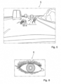
- the electronic component can be integrated into data glasses that the machine operator wears on his nose or in front of his eyes, whereby control data can be displayed on the data glasses.
- the data glasses for this purpose, for example, can have a head-up display that projects information onto at least one lens and/or have a transparent screen glass on which information can be displayed, for example, using the liquid crystal principle.
- the data glasses mentioned can also fulfill a function that supports the visual function, for example include ground optical glasses.
- contact lenses designed as head-up displays can also be used, which can display relevant information directly in front of the eye.
- the mobile electronic component can be integrated into an acoustic head set, which can include a loudspeaker that can be positioned on the ear and/or a microphone that can be positioned near the mouth in order to be able to acoustically output control and/or operating information and/or to be able to acoustically input control commands .
- the acoustically entered control commands can be detected using a voice recognition device and converted into corresponding control commands.
- a speech recognition device can also work properly in an acoustically unfavorable environment such as a construction site with a lot of background noise.
- said module can comprise optical and/or acoustic and/or tactile display means, for example in the form of a display and/or a buzzer and/or a loudspeaker and/or a vibration element.
- messages can be reported by vibrating the shoe and/or vibrating the glove and/or can also be shown on a display. Alternatively or additionally, an acoustic message can also be given.
- messages can be displayed on the display of the smartwatch or shown on the data glasses, whereby additional acoustic and/or tactile messages can also be emitted here.
- wearables or electronic components that can be worn on different body limbs display different control data or different information, so that the machine operator intuitively notices which control function is being displayed.
- a first operating parameter such as an imminent exceeding of the permissible load capacity of a crane can be displayed by vibrating the shoes and a second operating parameter such as approaching a working area limit can be displayed by vibrating a glove and a third operating parameter such as reaching a target position of a concrete bucket for this Concreting can be indicated by the buzzing of the smartwatch.
- separate electronic components and/or display modes on different items of clothing and/or on different body limbs can be assigned to different operating parameters and/or different machine functions.
- different display modes of the same electronic module can be assigned to different operating parameters and/or different control functions of the construction machine. For example, overcharging can be indicated by the gloves vibrating and reaching a working range limit can be indicated by LEDs on the glove lighting up.
- the various display signals mentioned can also be on different electronic components and/or on different sections of the functional clothing, for example the aforementioned overloading by vibrating the shoes and reaching a work area limit by lighting up the gloves.
- the at least one electronic module can fundamentally have different input means.
- a touchscreen can be provided which can generate input signals by touching it, such a touchscreen advantageously being able to display a menu control and/or a keypad in the manner of a keyboard in order to be able to enter writing commands.
- pressure or setting switches can be provided as input means, for example in the form of slide switches, push buttons or rocker arms, for example in the form of push buttons on a smartwatch.
- a piezo element can also be integrated into the functional part that can be worn on the body as an input means, for example in the form of a piezo membrane that is sewn, woven or integrated in some other way into a section of a piece of clothing.
- a piezo element can be integrated in the area of a finger of a finger glove, so that a corresponding control signal can be input by bending the finger and thus deforming the piezo element.
- such a piezo element can be integrated into the sole of a shoe, for example, so that an actuating signal can be generated, for example, by vigorously stomping on the ground.
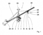
- the construction machine 2 can be designed as a crane, for example a tower crane, telescopic boom crane, harbor crane or offshore crane.
- the in Fig. 1 The tower crane shown can, for example, have a tower 201 in a manner known per se, which carries a boom 202, which is balanced by a counter-jib 203, on which a counterweight 204 is provided.
- the said boom 202 can be rotated together with the counter-jib 203 by a slewing mechanism about an upright axis of rotation 205, which can be coaxial to the tower axis.
- a trolley 206 can be moved on the boom 202 by a trolley drive, with a hoist rope 207 running from the trolley 206, to which a load hook 208 is attached.
- the construction machinery 2 can have an electronic control device 3, which can, for example, include a control computer arranged on the construction machine itself.
- the control device 3 mentioned can control various actuators, hydraulic circuits, electric motors, drive devices and other work units on the respective construction machine.
- this can include its hoisting mechanism, its slewing gear, its trolley drive, its -if applicable. existing - boom luffing drive or the like.
- the aforementioned electronic control device 3 can communicate with a terminal 4, which can be arranged at the control stand or in the driver's cab and can, for example, have the form of a tablet with a touchscreen and / or joysticks, so that, on the one hand, various information from the control computer 3 to the terminal 4 is displayed and conversely control commands can be entered into the control device 3 via the terminal 4.
- a terminal 4 can be arranged at the control stand or in the driver's cab and can, for example, have the form of a tablet with a touchscreen and / or joysticks, so that, on the one hand, various information from the control computer 3 to the terminal 4 is displayed and conversely control commands can be entered into the control device 3 via the terminal 4.
- the said control device 3 of the crane 1 can in particular be designed to control the said drive devices of the hoist, the trolley and the slewing gear even when the load hook 208 and / or a component received thereon, such as the one in Fig. 9 concrete bucket 50 shown is manipulated manually by a machine operator, ie is pushed or pulled and/or twisted in one direction or this is attempted in order to enable manual fine-tuning of the load hook and thus concrete bucket position, for example when concreting.
- the crane 1 can have a detection device 60, which detects a diagonal pull of the hoist rope 207 and/or deflections of the load hook 208 relative to a vertical 61, which passes through the suspension point of the load hook 208, i.e. the trolley 206.
- the determination means 62 of the detection device 60 can, for example, work optically in order to determine the deflection mentioned.
- a camera 63 or another imaging sensor system can be attached to the trolley 206, which looks vertically downwards from the trolley 206, so that when the load hook 208 is not deflected, its image reproduction is in the center of the image provided by the camera 63.
- the load hook 208 is deflected relative to the vertical 61, for example by manually pushing or pulling on the load hook 208 or the in Fig. 9 Concrete bucket 50 shown, the image reproduction of the load hook 208 moves out of the center of the camera image, which can be determined by an image evaluation device 64.
- the control device 3 can control the slewing gear drive and the trolley drive in order to bring the trolley 206 again more or less exactly over the load hook 208, ie the control device 3 controls the drive devices of the crane 1 in such a way that the diagonal pull or the detected Deflection is compensated as much as possible. This allows intuitive, simple directing and fine adjustment of the position of the load hook and a load picked up on it.
- said detection device 60 can also include a travel control module 65, which can be designed to be mobile and dockable to the load hook 208 and/or a load attached to it.
- a travel control module 65 can include, for example, a handle 66, which is preferably releasably attached to the load-carrying device 208 and/or a component articulated thereon, such as the concrete bucket 50, by means of suitable holding means 67 Fig. 9 can be attached.
- the holding means 67 mentioned can include, for example, magnet holders, suction cups, locking holders, bayonet lock holders or the like.
- Force and/or torque sensors 68 and, if necessary, in the case of a possible movable storage or design of the handle 66, also motion sensors can be assigned to the handle 66 mentioned, by means of which forces and/or moments and/or movements exerted on the handle 66 can be detected.
- the sensor system assigned to the handle 66 is advantageously designed in such a way that the forces and/or moments and/or movements can be detected with regard to their direction of action and/or magnitude.
- control device 3 can control the drive devices of the crane 1 in such a way that the detected manual manipulations are converted into motor crane positioning movements, such as this was explained in more detail at the beginning.
- the travel control module 65 can also include other operating elements 69, for example a tiltable and/or rotatable joystick, a touchscreen on which swiping movements and/or the depression of displayed movement symbols such as arrows and the like are detected, and/or slide switches and/or pushbuttons and/or rocker arms and the like.
- the actuation axes of the at least one control element 69 are linked to the movement axes of the crane 1 in order to enable intuitive operation of the crane, for example in such a way that upward manual operating movements move the crane hook upwards, and manipulation actions directed to the left move the crane hook move to the left etc.
- the travel control module 65 is detachably docked to the crane hook 208 and/or the component attached to it, it can be ensured that the movement is carried out by designing the docking means or the aforementioned holding means 67 and/or by specifying a docking position, for example using appropriate markings -Control module 65 is docked in the correct orientation.
- said control device 3 can also include mobile electronic components 5 in the form of so-called wearables, which are integrated into functional parts or clothing or clothing parts 6 that are intended to be worn on the body can be worn and held as intended by itself on the body without active gripping or balancing.
- the functional parts mentioned can be an item of clothing 7 such as a jacket 8 or trousers 9, which are shaped to fit the body and hold themselves on the body due to their shape adjustment, cf. Fig. 10 .
- aids such as belts, suspenders, zippers and the like can be used.
- the clothing items in which an electronic component 5 is integrated can also include a headgear 10 such as a headband, a hat or a helmet, and/or shoes 11, possibly also in the form of boots, and/or gloves 12 have.
- a headgear 10 such as a headband, a hat or a helmet, and/or shoes 11, possibly also in the form of boots, and/or gloves 12 have.
- Fig. 9 shows, for example, such gloves 12 with electronic components 5 integrated therein can be used to direct or finely adjust the position of the load hook 208 of the crane 1 or a concrete bucket 50 attached to it in a similar manner as described above.
- Such gloves 12 can, for example, include pressure- and/or direction-sensitive sensors 70, which can be integrated into fingertips or tips and/or the palm of the respective glove 12.
- the aforementioned sensors 70 can be used to detect in which direction the gloves 12 push, pull or rotate on the component or load-carrying device, in order to then use the control device 3 of the Crane 1 to carry out corresponding movements.
- position markings can be attached to the component to be moved, which specifies the contact or gripping position of the gloves 12, so that the control device 3 - from the component orientation on the crane hook 208 - knows in which direction the gloves 12 and their sensors 70 are working.
- the various sensors 70 of the gloves 12 can also be assigned different functions, for example in that a palm sensor of the right glove is assigned the function "horizontal movement from right to left", while the palm sensor of the left glove is assigned the function "vertical movement " assigned.
- a palm sensor of the right glove is assigned the function "horizontal movement from right to left”
- the palm sensor of the left glove is assigned the function "vertical movement " assigned.
- the finger sensor on the left glove can signal a move towards the operator and a finger sensor on the right glove can signal a move away.
- Other assignments of the sensors are of course possible.
- the gloves 12 can also have acceleration sensors and/or gyroscope elements, by means of which hand movements and their direction can be detected. This makes gesture control possible, for example in such a way that waving the glove upwards is converted into lifting the load hook.
- the aforementioned detection device 60 can also have a camera or an imaging sensor system or another optical detection device, by means of which hand movements or other body limb movements of a machine operator can be detected, particularly in the immediate vicinity of the load hook 208.
- a camera can be arranged at various locations, for example on the tower 201 and/or on the boom 202 and/or on the load hook 208 and/or on a flying drone and/or on the aforementioned travel control module 65, which is attached to the directing component can be docked.
- Image processing can evaluate the recorded movements of the machine operator, from which the control device 3 can then give the crane 1 travel commands.
- the image evaluation device can in particular be designed in such a way that the hand signals defined in DIN 33409 are captured or can be determined in the image provided by the camera.
- hand signals defined in the above-mentioned DIN standard are, for example, raising the right arm to indicate that hand signals will subsequently be given, or extending both arms horizontally to the side, which is interpreted as a stop signal to stop the crane movements and/or end a movement sequence , or a slight rocking of the palm up and down with the forearm extended horizontally to indicate the initiation of a slow downward movement.
- an electronic component can also be integrated into a personal accessory that is intended to be worn on the body and can fulfill a decorative function and/or other personal additional functions such as visual aids and the like.
- a personal accessory part can be data glasses 13, a watch 14, a finger ring, a bracelet or a belt and the like, in which an electronic component 5 for controlling and / or monitoring the construction machine 2 is integrated.
- FIG. 3 a watch 14 in the form of a smartwatch, which has a display on which various information relating to the operation of construction machinery can be displayed. If necessary, the smartwatches mentioned can also have a touchscreen, by means of which control commands can be entered into the control device of the construction machine.
- the mobile electronic component 5 can also be a tablet, which can be attached to a wrist by means of a bracelet or arm ring-like holding device and can also have a curved display itself, but which can otherwise work in the manner of a conventional tablet, i.e. also by means of a touchscreen function can generate control commands.
- Fig. 5 shows a mobile electronic component 5 in the form of a projection bracelet that can project an image onto a forearm.
- a detection function can be provided which can detect a fingertip or the like in the area of the projected image in order to enter control commands.
- FIG. 6 shows, for example, the data glasses 13, which are in Fig. 7 is shown, also work in the manner of a head-up display, in which additional information can be displayed in a transparent viewing window or a glass or a transparent plastic body, whereby an enriched reality in the sense of augmented reality can be generated.
- a mobile electronic component 5 which is designed and works in the form of a head-up display, can also be designed as a contact lens.
- the electronic components 5 mentioned can be assigned to different operating parameters and/or control functions of a construction machine 2, so that different operating parameters can be monitored and/or controlled on different body limbs.
- the hoist of the crane can be controlled and/or monitored with an electronic component 5 in the right glove 12, while, for example, the trolley of the crane 2 can be controlled or monitored with an electronic component 5 in the left glove.
- the electronic components 5 designed to be mobile and/or in the form of wearables can communicate wirelessly with the respective construction machine 2. This can be done, for example, via Bluetooth, in which case the control device 3 on the construction machine 2 can have a Bluetooth adapter 7, for example on the load hook block, via which the respective electronic module 5 can be connected to the control device 3.
- the respective electronic component 5 also includes a Bluetooth transmitting and/or receiving device.
- the data communication between the electronic components 5 and the control computer 3 of the construction machine 2 is advantageously bidirectional, so that both monitored operating parameters can be displayed on the electronic component 5 and control commands can be entered on the electronic component 5.
- the electronic components 5 can have input means designed in the manner described at the outset for entering control commands and display means for displaying control data and/or monitored operating parameters, as also described at the outset.
Applications Claiming Priority (3)
| Application Number | Priority Date | Filing Date | Title |
|---|---|---|---|
| DE202016002296.3U DE202016002296U1 (de) | 2016-04-08 | 2016-04-08 | Baumaschine |
| EP17716791.3A EP3408209B1 (fr) | 2016-04-08 | 2017-04-07 | Engin de chantier |
| PCT/EP2017/000459 WO2017174204A2 (fr) | 2016-04-08 | 2017-04-07 | Engin de chantier |
Related Parent Applications (1)
| Application Number | Title | Priority Date | Filing Date |
|---|---|---|---|
| EP17716791.3A Division EP3408209B1 (fr) | 2016-04-08 | 2017-04-07 | Engin de chantier |
Publications (1)
| Publication Number | Publication Date |
|---|---|
| EP4276047A2 true EP4276047A2 (fr) | 2023-11-15 |
Family
ID=59409880
Family Applications (2)
| Application Number | Title | Priority Date | Filing Date |
|---|---|---|---|
| EP23199748.7A Pending EP4276047A2 (fr) | 2016-04-08 | 2017-04-07 | Machine de construction |
| EP17716791.3A Active EP3408209B1 (fr) | 2016-04-08 | 2017-04-07 | Engin de chantier |
Family Applications After (1)
| Application Number | Title | Priority Date | Filing Date |
|---|---|---|---|
| EP17716791.3A Active EP3408209B1 (fr) | 2016-04-08 | 2017-04-07 | Engin de chantier |
Country Status (8)
| Country | Link |
|---|---|
| US (1) | US11014789B2 (fr) |
| EP (2) | EP4276047A2 (fr) |
| CN (2) | CN109071186B (fr) |
| BR (1) | BR112018070570A2 (fr) |
| DE (1) | DE202016002296U1 (fr) |
| ES (1) | ES2966893T3 (fr) |
| RU (2) | RU2754118C2 (fr) |
| WO (1) | WO2017174204A2 (fr) |
Families Citing this family (9)
| Publication number | Priority date | Publication date | Assignee | Title |
|---|---|---|---|---|
| EP3409849B1 (fr) * | 2016-01-29 | 2023-10-18 | Sumitomo (S.H.I.) Construction Machinery Co., Ltd. | Excavatrice et corps volant autonome pour voler autour d'une excavatrice |
| US11130658B2 (en) * | 2016-11-22 | 2021-09-28 | Manitowoc Crane Companies, Llc | Optical detection and analysis of a counterweight assembly on a crane |
| DE102017214398A1 (de) * | 2017-08-18 | 2019-02-21 | Jenoptik Advanced Systems Gmbh | Handsteuergerät zum Bedienen einer Seilwinde, Seilwindensystem und Verfahren zum Informieren eines Bedieners einer Seilwinde mittels eines Handsteuergeräts |
| DE102017124278A1 (de) * | 2017-10-18 | 2019-04-18 | Konecranes Global Corporation | System zum Bedienen eines Lasthandling-Krans sowie Lasthandling-Kran und Verfahren zu dessen Bedienung |
| DE102018109234B4 (de) * | 2018-04-18 | 2021-03-11 | Abus Kransysteme Gmbh | Vorrichtung und Verfahren zur Steuerung eines Kransystems |
| DE102020112227A1 (de) | 2019-11-22 | 2021-05-27 | Liebherr-Werk Biberach Gmbh | Bau- und/oder Materialumschlagsmaschine |
| CN112130521B (zh) * | 2020-09-22 | 2021-04-20 | 郑州嘉晨电器有限公司 | 一种用于工程机械安全操控的控制装置 |
| CN112279099B (zh) * | 2020-10-23 | 2023-08-29 | 三一汽车起重机械有限公司 | 起重机作业辅助系统以及方法 |
| CN113526348B (zh) * | 2021-06-30 | 2024-01-30 | 中国人民解放军空军工程大学 | 一种具备听觉和触觉提示功能的吊具系统及其使用方法 |
Family Cites Families (26)
| Publication number | Priority date | Publication date | Assignee | Title |
|---|---|---|---|---|
| JPS5495442A (en) | 1978-01-11 | 1979-07-27 | Kobe Steel Ltd | Method and device for controlling ingot stripper crane |
| NO164946C (no) * | 1988-04-12 | 1990-11-28 | Metronor As | Opto-elektronisk system for punktvis oppmaaling av en flates geometri. |
| US5227985A (en) * | 1991-08-19 | 1993-07-13 | University Of Maryland | Computer vision system for position monitoring in three dimensions using non-coplanar light sources attached to a monitored object |
| DE4315005A1 (de) * | 1993-05-06 | 1994-11-10 | Deutsche Aerospace | Vorrichtung zur meßtechnischen Erfassung von Winkellagen eines bewegten Gegenstandes gegenüber seiner Ausgangsstellung |
| DE19825312B4 (de) * | 1997-07-15 | 2005-09-01 | Münnekehoff, Gerd, Dipl.-Ing. | System zum Steuern der Bewegungen einer Lasthebevorrichtung |
| JP2002049403A (ja) * | 2000-08-07 | 2002-02-15 | Shin Caterpillar Mitsubishi Ltd | 建設機械における音声機体制御装置 |
| US6575317B2 (en) | 2000-10-18 | 2003-06-10 | Gorbel, Inc. | Pendant-responsive crane control |
| US6554252B2 (en) * | 2001-09-28 | 2003-04-29 | Homayoon Kazerooni | Device and method for wireless lifting assist devices |
| US7185774B2 (en) * | 2002-05-08 | 2007-03-06 | The Stanley Works | Methods and apparatus for manipulation of heavy payloads with intelligent assist devices |
| EP3190572B1 (fr) * | 2006-09-14 | 2018-12-12 | Crown Equipment Corporation | Procédé de commande à distance d'un véhicule de manipulation de matériaux |
| US8970363B2 (en) * | 2006-09-14 | 2015-03-03 | Crown Equipment Corporation | Wrist/arm/hand mounted device for remotely controlling a materials handling vehicle |
| DE102007012575A1 (de) * | 2007-03-13 | 2008-09-18 | Putzmeister Concrete Pumps Gmbh | Großmanipulator |
| JP5215725B2 (ja) | 2008-05-13 | 2013-06-19 | 株式会社キトー | 走行クレーンの操作制御装置、操作制御方法 |
| KR101726209B1 (ko) * | 2009-07-02 | 2017-04-12 | 크라운 이큅먼트 코포레이션 | 물류 취급 차량을 원격으로 제어하기 위한 장치 |
| DE102009032270A1 (de) | 2009-07-08 | 2011-01-13 | Liebherr-Werk Nenzing Gmbh | Verfahren zur Ansteuerung eines Antriebs eines Kranes |
| DE102011002952A1 (de) * | 2011-01-21 | 2012-07-26 | BSH Bosch und Siemens Hausgeräte GmbH | Bewegliche Vorrichtung |
| US8831794B2 (en) * | 2011-05-04 | 2014-09-09 | Qualcomm Incorporated | Gesture recognition via an ad-hoc proximity sensor mesh for remotely controlling objects |
| CN102515026B (zh) | 2011-12-30 | 2014-01-15 | 大连华锐重工集团股份有限公司 | 锻造起重机的随动控制系统 |
| US9279679B2 (en) * | 2012-09-12 | 2016-03-08 | Kabushiki Kaisha Topcon | Construction machine control method and construction machine control system |
| DE102012110190B4 (de) | 2012-10-25 | 2015-03-26 | Mis-Robotics Gmbh | Manuell betätigte Robotersteuerung und Verfahren zum Steuern eines Robotersystems |
| CN103101838B (zh) | 2013-01-31 | 2014-10-15 | 中联重科股份有限公司 | 一种塔臂随动控制设备、方法、系统及工程机械 |
| DE102013209279A1 (de) * | 2013-05-21 | 2014-11-27 | Zf Friedrichshafen Ag | Eine Vorrichtung und ein Verfahren zum Erzeugen eines Steuersignals zur Steuerung einer Arbeitsmaschine |
| DE202013011913U1 (de) * | 2013-08-29 | 2014-10-07 | Eisenmann Ag | Industrieanlage mit einer mobilen Bedieneinheit |
| CN105022353A (zh) * | 2014-04-19 | 2015-11-04 | 浙江福爱电子有限公司 | 基于智能穿戴设备的车辆信息系统与信息交换方法 |
| KR102188267B1 (ko) * | 2014-10-02 | 2020-12-08 | 엘지전자 주식회사 | 이동단말기 및 그 제어방법 |
| US20170111723A1 (en) * | 2015-10-20 | 2017-04-20 | Bragi GmbH | Personal Area Network Devices System and Method |
-
2016
- 2016-04-08 DE DE202016002296.3U patent/DE202016002296U1/de active Active
-
2017
- 2017-04-07 RU RU2020137102A patent/RU2754118C2/ru active
- 2017-04-07 US US16/092,086 patent/US11014789B2/en active Active
- 2017-04-07 EP EP23199748.7A patent/EP4276047A2/fr active Pending
- 2017-04-07 BR BR112018070570-5A patent/BR112018070570A2/pt not_active Application Discontinuation
- 2017-04-07 EP EP17716791.3A patent/EP3408209B1/fr active Active
- 2017-04-07 CN CN201780022336.XA patent/CN109071186B/zh active Active
- 2017-04-07 CN CN202011000225.9A patent/CN112158734B/zh active Active
- 2017-04-07 RU RU2018139155A patent/RU2736896C2/ru active
- 2017-04-07 WO PCT/EP2017/000459 patent/WO2017174204A2/fr active Application Filing
- 2017-04-07 ES ES17716791T patent/ES2966893T3/es active Active
Also Published As
| Publication number | Publication date |
|---|---|
| EP3408209A2 (fr) | 2018-12-05 |
| RU2736896C2 (ru) | 2020-11-23 |
| WO2017174204A2 (fr) | 2017-10-12 |
| DE202016002296U1 (de) | 2017-07-12 |
| CN112158734A (zh) | 2021-01-01 |
| BR112018070570A2 (pt) | 2019-02-12 |
| RU2020137102A (ru) | 2020-12-01 |
| EP3408209B1 (fr) | 2023-09-27 |
| CN112158734B (zh) | 2023-10-20 |
| RU2754118C2 (ru) | 2021-08-26 |
| WO2017174204A3 (fr) | 2017-12-28 |
| CN109071186B (zh) | 2020-10-02 |
| US20190177131A1 (en) | 2019-06-13 |
| ES2966893T3 (es) | 2024-04-24 |
| US11014789B2 (en) | 2021-05-25 |
| RU2018139155A (ru) | 2020-05-12 |
| CN109071186A (zh) | 2018-12-21 |
| RU2020137102A3 (fr) | 2021-02-17 |
| RU2018139155A3 (fr) | 2020-10-02 |
Similar Documents
| Publication | Publication Date | Title |
|---|---|---|
| EP3408209B1 (fr) | Engin de chantier | |
| EP3497048B1 (fr) | Poste de commande pour une grue, excavateur et similaire | |
| CN109906198B (zh) | 用于起重机、施工机械和/或工业卡车的遥控装置 | |
| EP3081347B1 (fr) | Appareil de commande manuel de robot, appareil et systeme en communication avec cet appareil | |
| CN104898524B (zh) | 基于手势的无人机遥控系统 | |
| WO2017065093A1 (fr) | Dispositif d'actionnement à distance et système d'instruction | |
| RU2021100284A (ru) | Устройство дистанционного управления для крана, строительной машины и/или автопогрузчика | |
| CN111837382B (zh) | 工程机械的远程操作系统 | |
| JP2015511544A (ja) | ロボットに用いる手動制御補助装置 | |
| US20060212168A1 (en) | Robot remote control system | |
| US20200376657A1 (en) | Teaching Method | |
| JP2019173379A (ja) | 遠隔操作システム及び主操作装置 | |
| EP3089493A1 (fr) | Outillage agricole | |
| JP2021167253A (ja) | 可視化装置を備えたクレーン制御装置 | |
| EP3923569B1 (fr) | Système de manoeuvre à distance et serveur de manoeuvre à distance | |
| EP3923594A1 (fr) | Système de fonctionnement à distance | |
| KR101863460B1 (ko) | 전동보드조작시스템 | |
| DE102018109326B4 (de) | Mehrgliedrige aktuierte Kinematik, vorzugsweise Roboter, besonders vorzugsweise Knickarmroboter | |
| KR102063520B1 (ko) | 시뮬레이션 장치 | |
| EP4038009A1 (fr) | Machine de construction et/ou de manipulation de matériaux | |
| JP2001173022A (ja) | 遠隔操作によるツインアーム作業機 | |
| JP2003170375A (ja) | ロボット遠隔制御システム | |
| CN114803858A (zh) | 智能塔机体感控制系统及智能塔机体感控制方法 |
Legal Events
| Date | Code | Title | Description |
|---|---|---|---|
| PUAI | Public reference made under article 153(3) epc to a published international application that has entered the european phase |
Free format text: ORIGINAL CODE: 0009012 |
|
| STAA | Information on the status of an ep patent application or granted ep patent |
Free format text: STATUS: THE APPLICATION HAS BEEN PUBLISHED |
|
| AC | Divisional application: reference to earlier application |
Ref document number: 3408209 Country of ref document: EP Kind code of ref document: P |
|
| AK | Designated contracting states |
Kind code of ref document: A2 Designated state(s): AL AT BE BG CH CY CZ DE DK EE ES FI FR GB GR HR HU IE IS IT LI LT LU LV MC MK MT NL NO PL PT RO RS SE SI SK SM TR |
|
| REG | Reference to a national code |
Ref country code: DE Ref legal event code: R079 Free format text: PREVIOUS MAIN CLASS: B66C0013460000 Ipc: B66C0013400000 |
|
| RIC1 | Information provided on ipc code assigned before grant |
Ipc: B66C 13/30 20060101ALI20231222BHEP Ipc: B66C 13/08 20060101ALI20231222BHEP Ipc: B66C 13/46 20060101ALI20231222BHEP Ipc: G05B 19/042 20060101ALI20231222BHEP Ipc: B66C 13/40 20060101AFI20231222BHEP |
|
| PUAL | Search report despatched |
Free format text: ORIGINAL CODE: 0009013 |