EP4248172B1 - Optische validierung von ausrichtungen von internen facetten - Google Patents
Optische validierung von ausrichtungen von internen facetten Download PDFInfo
- Publication number
- EP4248172B1 EP4248172B1 EP21894198.7A EP21894198A EP4248172B1 EP 4248172 B1 EP4248172 B1 EP 4248172B1 EP 21894198 A EP21894198 A EP 21894198A EP 4248172 B1 EP4248172 B1 EP 4248172B1
- Authority
- EP
- European Patent Office
- Prior art keywords
- sample
- incident
- returned
- light
- optical
- Prior art date
- Legal status (The legal status is an assumption and is not a legal conclusion. Google has not performed a legal analysis and makes no representation as to the accuracy of the status listed.)
- Active
Links
Images


Classifications
-
- G—PHYSICS
- G01—MEASURING; TESTING
- G01B—MEASURING LENGTH, THICKNESS OR SIMILAR LINEAR DIMENSIONS; MEASURING ANGLES; MEASURING AREAS; MEASURING IRREGULARITIES OF SURFACES OR CONTOURS
- G01B11/00—Measuring arrangements characterised by the use of optical techniques
- G01B11/26—Measuring arrangements characterised by the use of optical techniques for measuring angles or tapers; for testing the alignment of axes
-
- G—PHYSICS
- G01—MEASURING; TESTING
- G01N—INVESTIGATING OR ANALYSING MATERIALS BY DETERMINING THEIR CHEMICAL OR PHYSICAL PROPERTIES
- G01N21/00—Investigating or analysing materials by the use of optical means, i.e. using sub-millimetre waves, infrared, visible or ultraviolet light
- G01N21/17—Systems in which incident light is modified in accordance with the properties of the material investigated
- G01N21/41—Refractivity; Phase-affecting properties, e.g. optical path length
-
- G—PHYSICS
- G01—MEASURING; TESTING
- G01C—MEASURING DISTANCES, LEVELS OR BEARINGS; SURVEYING; NAVIGATION; GYROSCOPIC INSTRUMENTS; PHOTOGRAMMETRY OR VIDEOGRAMMETRY
- G01C9/00—Measuring inclination, e.g. by clinometers, by levels
- G01C9/02—Details
- G01C9/06—Electric or photoelectric indication or reading means
-
- G—PHYSICS
- G01—MEASURING; TESTING
- G01M—TESTING STATIC OR DYNAMIC BALANCE OF MACHINES OR STRUCTURES; TESTING OF STRUCTURES OR APPARATUS, NOT OTHERWISE PROVIDED FOR
- G01M11/00—Testing of optical apparatus; Testing structures by optical methods not otherwise provided for
- G01M11/02—Testing optical properties
- G01M11/0242—Testing optical properties by measuring geometrical properties or aberrations
-
- G—PHYSICS
- G01—MEASURING; TESTING
- G01N—INVESTIGATING OR ANALYSING MATERIALS BY DETERMINING THEIR CHEMICAL OR PHYSICAL PROPERTIES
- G01N21/00—Investigating or analysing materials by the use of optical means, i.e. using sub-millimetre waves, infrared, visible or ultraviolet light
- G01N21/01—Arrangements or apparatus for facilitating the optical investigation
-
- G—PHYSICS
- G01—MEASURING; TESTING
- G01N—INVESTIGATING OR ANALYSING MATERIALS BY DETERMINING THEIR CHEMICAL OR PHYSICAL PROPERTIES
- G01N21/00—Investigating or analysing materials by the use of optical means, i.e. using sub-millimetre waves, infrared, visible or ultraviolet light
- G01N21/17—Systems in which incident light is modified in accordance with the properties of the material investigated
- G01N21/59—Transmissivity
-
- G—PHYSICS
- G02—OPTICS
- G02B—OPTICAL ELEMENTS, SYSTEMS OR APPARATUS
- G02B17/00—Systems with reflecting surfaces, with or without refracting elements
- G02B17/02—Catoptric systems, e.g. image erecting and reversing system
- G02B17/023—Catoptric systems, e.g. image erecting and reversing system for extending or folding an optical path, e.g. delay lines
-
- G—PHYSICS
- G02—OPTICS
- G02B—OPTICAL ELEMENTS, SYSTEMS OR APPARATUS
- G02B27/00—Optical systems or apparatus not provided for by any of the groups G02B1/00 - G02B26/00, G02B30/00
- G02B27/10—Beam splitting or combining systems
- G02B27/12—Beam splitting or combining systems operating by refraction only
- G02B27/126—The splitting element being a prism or prismatic array, including systems based on total internal reflection
-
- G—PHYSICS
- G02—OPTICS
- G02B—OPTICAL ELEMENTS, SYSTEMS OR APPARATUS
- G02B27/00—Optical systems or apparatus not provided for by any of the groups G02B1/00 - G02B26/00, G02B30/00
- G02B27/42—Diffraction optics, i.e. systems including a diffractive element being designed for providing a diffractive effect
- G02B27/4233—Diffraction optics, i.e. systems including a diffractive element being designed for providing a diffractive effect having a diffractive element [DOE] contributing to a non-imaging application
- G02B27/4255—Diffraction optics, i.e. systems including a diffractive element being designed for providing a diffractive effect having a diffractive element [DOE] contributing to a non-imaging application for alignment or positioning purposes
-
- G—PHYSICS
- G02—OPTICS
- G02B—OPTICAL ELEMENTS, SYSTEMS OR APPARATUS
- G02B27/00—Optical systems or apparatus not provided for by any of the groups G02B1/00 - G02B26/00, G02B30/00
- G02B27/62—Optical apparatus specially adapted for adjusting optical elements during the assembly of optical systems
-
- G—PHYSICS
- G01—MEASURING; TESTING
- G01C—MEASURING DISTANCES, LEVELS OR BEARINGS; SURVEYING; NAVIGATION; GYROSCOPIC INSTRUMENTS; PHOTOGRAMMETRY OR VIDEOGRAMMETRY
- G01C9/00—Measuring inclination, e.g. by clinometers, by levels
- G01C9/02—Details
- G01C9/06—Electric or photoelectric indication or reading means
- G01C2009/066—Electric or photoelectric indication or reading means optical
-
- G—PHYSICS
- G01—MEASURING; TESTING
- G01N—INVESTIGATING OR ANALYSING MATERIALS BY DETERMINING THEIR CHEMICAL OR PHYSICAL PROPERTIES
- G01N21/00—Investigating or analysing materials by the use of optical means, i.e. using sub-millimetre waves, infrared, visible or ultraviolet light
- G01N21/01—Arrangements or apparatus for facilitating the optical investigation
- G01N2021/0106—General arrangement of respective parts
- G01N2021/0112—Apparatus in one mechanical, optical or electronic block
-
- G—PHYSICS
- G01—MEASURING; TESTING
- G01N—INVESTIGATING OR ANALYSING MATERIALS BY DETERMINING THEIR CHEMICAL OR PHYSICAL PROPERTIES
- G01N21/00—Investigating or analysing materials by the use of optical means, i.e. using sub-millimetre waves, infrared, visible or ultraviolet light
- G01N21/84—Systems specially adapted for particular applications
- G01N21/88—Investigating the presence of flaws or contamination
- G01N21/95—Investigating the presence of flaws or contamination characterised by the material or shape of the object to be examined
- G01N2021/9511—Optical elements other than lenses, e.g. mirrors
Definitions
- the present disclosure relates generally to methods and systems for metrology of samples including internal facets.
- Some transparent optical elements such as glass prisms and waveguides, may include reflective, internal facets.
- reflective, internal facets In order to validate to high precision the orientation of such a facet relative to one or more external surfaces of the optical element, current state-of-the-art techniques require high-end optical components and implementation of complex alignment and calibration procedures.
- DE102013001458A1 discloses a system for determining the position of a test object, comprising an autocollimation telescope having a beam source for emitting a beam; a beam splitter; a detector unit and an objective lens; and an optical element embodied as a focusing device, wherein the test object, the beam source and the focusing device are arranged along a common optical axis, and a control device for controlling the focusing device, which is designed in such a way that the beam can be focused onto a centre of curvature of a first test surface of the test object and at least onto a centre of curvature of a second test surface of the test object with coordinates.
- the present invention relates to an optical-based system according to the appended claims.
- an optical-based system for validating an orientation of an internal facet of a sample relative to an external, flat surface of the sample includes:
- the measured first angular deviation is indicative of an actual inclination angle of the internal facet relative to the first surface.
- the light generation assembly includes a light source and optical equipment.
- the at least one sensor includes one or more light sensors and/or one or more image sensors (e.g. one or more cameras).
- the sample includes a first part and a second part, between which the internal facet extends.
- the first part is positioned between an external second surface of the sample and the internal facet.
- the LGA is configured to redirect the second incident LB into or onto the first part via the second surface.
- the LGA includes a light folding component (LFC) nominally configured to fold light, at least when projected thereon in a direction perpendicular to the first surface, at a light folding angle equal to the nominal inclination angle.
- LFC light folding component
- the LFC is or includes a prism, one or more mirrors, and/or a diffraction grating.
- the light folding angle of the LFC is insensitive to variations in a pitch of the LFC.
- the LFC is or includes a pentaprism or a like-function prism, or a pair of mirrors set at an angle relative to one another or a like-function mirror arrangement.
- the LGA further includes a coupling infrastructure configured to guide the light, folded by the LFC, onto or into the sample, such that light, transmitted thereby into the sample, nominally normally impinges on the internal facet.
- the coupling infrastructure includes a coupling prism (CP), including an external, flat CP first surface, an external, flat CP second surface, nominally inclined at the nominal angle relative to the CP first surface, and an external CP third surface (which may be flat or not), opposite the CP second surface.
- the CP has a same refractive index as the first part of the sample or a refractive index close to (e.g. to within 0.001%, 0.01%, or even 0.1%, each possibility corresponds to separate embodiments) that of the first part of the sample.
- the CP is disposed such that the CP first surface is parallel to the first surface of the sample, and is further oriented such that the light, folded by the LFC, nominally normally impinges on the CP second surface.
- the coupling infrastructure further includes a shape-compliant interface.
- the shape-compliant interface is disposed between the CP third surface and the sample, such that the CP first surface is parallel to the first surface of the sample.
- the shape-compliant interface has a same refractive index as the first part of the sample or a refractive index close to (e.g. to within 0.001 %, 0.01%, or even 0.1 %, each possibility corresponds to separate embodiments) that of the first part of the sample.
- the shape-compliant interface is or includes a liquid and/or a gel.
- the sample may be a prism, a waveguide, or a beam splitter.
- the system further includes a computational module configured to compute the actual inclination angle, based at least on the measured first angular deviation.
- the computational module is further configured to compute an uncertainty in the computed value of the actual inclination angle, taking into account at least manufacturing tolerances and imperfections of the LGA and the ICA.
- the system further includes orienting infrastructure configured to orient the sample such that the first incident LB normally impinges on the first surface, and/or a folded LB, obtained by folding of the second incident LB by the LFC, nominally normally impinges on the CP second surface.
- the system further includes an autocollimator.
- the autocollimator includes the light source, the at least one sensor, and a collimating lens or collimating lens assembly.
- the ICA further includes at least two shutters configured to selectively block each of the incident LBs, and/or one or more spectral filters configured to at least facilitate distinguishing between the returned LBs.
- the nominal inclination angle is 90° and the sample further includes an external, flat third surface, which is parallel to the first surface.
- the system is configured to facilitate flipping the sample.
- the computational module is configured to compute the actual inclination angle additionally taking into account a measured second angular deviation of a fourth returned LB relative to a third returned LB.
- the third returned LB is obtained by projecting a third incident light beam on the third surface of the sample, so as to generate the third returned LB by reflection off the third surface
- ( b' ) and the fourth returned LB is obtained by projecting a fourth incident LB on the LFC, in parallel to the third incident LB, so as generate the fourth returned LB, by redirection by the LGA of the fourth incident LB into or onto the sample, reflection thereof off the internal facet, and inverse redirection by the LGA.
- the CP further includes an external, flat CP fourth surface, which is parallel to the CP first surface.
- the CP is mechanically flippable, such that the CP first surface and the CP fourth surface may be inverted, while maintaining a nominal orientation of the CP second surface relative to the sample.
- the measured second angular deviation is obtained with the CP flipped, such that the CP first surface and the CP fourth surface are inverted and the nominal orientation of the CP second surface relative to the sample is maintained.
- the computational module is configured to compute the uncertainty in the computed value of the actual inclination angle additionally taking into account manufacturing tolerances and imperfections of the orienting infrastructure.
- the light generation assembly includes a light source and optical equipment
- the light source is configured to generate a single LB
- the optical equipment is configured to collimate the single LB
- the first incident LB and the second incident LB are complementary portions of the collimated LB.
- the light source is a polychromatic light source.
- the light source is configured to generate a laser beam.
- Certain embodiments of the present disclosure may include some, all, or none of the above advantages.
- One or more other technical advantages may be readily apparent to those skilled in the art from the figures, descriptions, and claims included herein.
- specific advantages have been enumerated above, various embodiments may include all, some, or none of the enumerated advantages.
- terms such as “processing”, “computing”, “calculating”, “determining”, “estimating”, “assessing”, “gauging” or the like may refer to the action and/or processes of a computer or computing system, or similar electronic computing device, that manipulate and/or transform data, represented as physical (e.g. electronic) quantities within the computing system's registers and/or memories, into other data similarly represented as physical quantities within the computing system's memories, registers or other such information storage, transmission or display devices.
- Embodiments of the present disclosure may include apparatuses for performing the operations herein.
- the apparatuses may be specially constructed for the desired purposes or may include a general-purpose computer(s) selectively activated or reconfigured by a computer program stored in the computer.
- a computer program may be stored in a computer readable storage medium, such as, but not limited to, any type of disk including floppy disks, optical disks, CD-ROMs, magnetic-optical disks, read-only memories (ROMs), random access memories (RAMs), electrically programmable read-only memories (EPROMs), electrically erasable and programmable read only memories (EEPROMs), magnetic or optical cards, or any other type of media suitable for storing electronic instructions, and capable of being coupled to a computer system bus.
- program modules include routines, programs, objects, components, data structures, and so forth, which perform particular tasks or implement particular abstract data types.
- Disclosed embodiments may also be practiced in distributed computing environments where tasks are performed by remote processing devices that are linked through a communications network.
- program modules may be located in both local and remote computer storage media including memory storage devices.
- the term "about” may be used to specify a value of a quantity or parameter (e.g. the length of an element) to within a continuous range of values in the neighborhood of (and including) a given (stated) value. According to some embodiments, “about” may specify the value of a parameter to be between 80 % and 120 % of the given value. For example, the statement “the length of the element is equal to about 1 m” is equivalent to the statement “the length of the element is between 0.8 m and 1.2 m”. According to some embodiments, “about” may specify the value of a parameter to be between 90 % and 110 % of the given value. According to some embodiments, "about” may specify the value of a parameter to be between 95 % and 105 % of the given value.
- the terms “substantially” and “about” may be interchangeable.
- a three-dimensional cartesian coordinate system is introduced. It is noted that the orientation of the coordinate system relative to a depicted object may vary from one figure to another. Further, the symbol ⁇ may be used to represent an axis pointing "out of the page", while the symbol ⁇ may be used to represent an axis pointing "into the page”.
- internal, flat surfaces (such as a flat boundary between two parts of a three-dimensional element or an internal flat layer of material incorporated into a three-dimensional element) of three-dimensional elements are referred to as "internal facets”.
- an optical-based system for internal facet metrology of samples Fig. 1A schematically depicts such a system, an optical-based system 100, according to some embodiments.
- Optical-based system 100 is configured for validating the angle between an internal facet of a sample and an external, flat surface of the sample.
- Fig. 1A presents a cross-sectional side-view of system 100 and a sample 10, according to some embodiments. (It is to be understood that sample 10 does not constitute a part of system 100 .) Sample 10 is shown being inspected by system 100.
- Sample 10 includes an external first surface 12a (i.e. a first external surface), an external second surface 12b (i.e. a second external surface), and an internal facet 14.
- First surface 12a is flat.
- the remaining external surfaces of sample 10 may be of any shape, for example, curved, so long as their shapes do not preclude positioning and orienting of sample 10, as elaborated on below.
- second surface 12b is depicted as convex, but it is to be understood that second surface 12b may equally be flat, concave, or even wavy or rough (e.g. unpolished), or include a plurality of non-parallel flat surfaces.
- sample 10 may be shaped as a polyhedron.
- Sample 10 is composed at least of a first part 16a and a second part 16b.
- first part 16a and second part 16b share a common boundary, which is flat, and constituted by internal facet 14.
- first part 16a and second part 16b are characterized by different refractive indices, respectively (i.e. a refractive index of first part 16a differs from a refractive index of second part 16b ).
- the sample may be an element composed of two glass parts, which are characterized by two different refractive indices, respectively.
- first part 16a and second part 16b may be separated by a thin and flat layer of material, or several materials, formed by internal facet 14.
- the layer is characterized by a different refractive index than at least one of first part 16a and second part 16b (whose refractive indices may or may not be identical).
- first part 16a and second part 16b may be made of the same material, for example, in embodiments wherein sample 10 is a prism or a waveguide and a flat layer (stratum) of material - having a different refractive index than that of first part 16a and/or second part 16b - is incorporated into sample 10 between first part 16a and second part 16b.
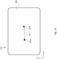
- Sample 10 is manufactured to exhibit a (nominal) inclination angle ⁇ (indicated in Fig. 1B ) between first surface 12a and internal facet 14.
- a straight (first) dashed line L is shown in Fig. 1A intersecting internal facet 14 and is inclined at the nominal inclination angle ⁇ relative to first surface 12a.
- the dashed line L indicates the intended inclination of internal facet 14.
- the nominal inclination angle ⁇ may be acute (i.e. ⁇ ⁇ 90°), obtuse (i.e. ⁇ > 90°), or equal to 90°.
- the orientation of internal facet 14 is, in principle not limited. Several different orientations of internal facets - whose (actual) inclination angles may be measured utilizing system 100 - within samples sharing the same exterior geometry, are described below in the description of Figs. 4A-4D .
- first part 16a may be made of a transparent or semi-transparent material
- second part 16b may be made of a transparent material or a semi-transparent material, or even an opaque material.
- first part 16a may be made of glass or crystal (or even transparent or semi-transparent polymer or metal), while second part 16b may in principle be made of any material (including opaque materials).
- first part 16a and second part 16b may be glued onto one another and/or fused (e.g. laser fused) onto another along the common boundary thereof.
- System 100 includes a light guiding arrangement (LGA) 102 and an illumination and collection arrangement (or assembly; ICA) 104.
- System 100 may further include a controller 108 functionally associated with ICA 104 and configured to control operation thereof.
- ICA 104 includes a light source 112 (or a plurality of light sources) and a sensor 114 (or a plurality of sensors).
- ICA 104 includes an eyepiece assembly in place of sensor 114, being thereby configured for visual determination (i.e. by eye) of the actual inclination angle.
- ICA 104 is configured to output at least two parallel light beams (LBs) including a first LB 105a (also referred to as “first incident LB”; indicated in Fig. 1A by a pair of parallel light rays) and a second LB 105b (also referred to as “second incident LB”; indicated in Fig. 1A by a pair of parallel light rays).
- LBs parallel light beams
- optical equipment 118 may be configured to collimate light generated by light source 112, and thereby produce the (parallel) incident LBs 105a and 105b.
- optical equipment 118 may include a collimating lens or a collimating lens assembly (not shown).
- incident LBs 105a and 105b may form complementary portions of a collimated light beam (which has been focused by the collimating lens or collimating lens assembly).
- incident LBs 105a and 105b may be spaced apart (and parallel).
- optical equipment 118 may further include one or more optical filters (e.g. a light absorbing filter or an opaque plate), and/or one or more beam splitters, and, optionally, one or more mirrors (not shown), configured to prepare from the collimated light beam a pair of spaced apart and parallel light beams.
- optical equipment 118 may further include a plurality of blocking elements (such as the blocking elements depicted in Fig. 2 ) configured to allow selectively blocking each of incident LBs 105 or at least facilitate distinguishing between a first returned LB 133a, induced by first incident LB 105, and a second returned LB 133b, induced by second incident LB 105b.
- a plurality of blocking elements such as the blocking elements depicted in Fig. 2 ) configured to allow selectively blocking each of incident LBs 105 or at least facilitate distinguishing between a first returned LB 133a, induced by first incident LB 105, and a second returned LB 133b, induced by second incident LB 105b.
- blocking element with reference to an optical element, is be construed broadly as encompassing both controllably openable and closable opaque elements (such as shutters) configured to (when closed) block light beams incident thereon, and filtering elements (such as spectral filters) configured to block, whether fully or partially, one or more parts of an optical spectrum (e.g. the visible spectrum).
- controllably openable and closable opaque elements such as shutters
- filtering elements such as spectral filters
- light source 112 may be configured to produce or allow producing polychromatic light. According to some such embodiments, the spectrum of the light may be controllable. According to some embodiments, light source 112 may be configured to produce or allow producing monochromatic light.
- ICA 104 is or includes an autocollimator (i.e. light source 112, sensor 114, and some or all of optical equipment 118 constitute components of the autocollimator).
- incident LBs 105 constitute adjacent sub-beams of a single, broad, and collimated LB generated by the autocollimator.
- optical equipment 118 may include an optical filter configured to transmit two sub-beams (such as incident LBs 105 ) of the collimated LB, prepared by the autocollimator and incident on the optical filter (with the parallelism of the two sub-beams being maintained on emergence from the optical filter).
- LGA 102 includes a light folding component 122 (LFC) and a coupling infrastructure 124, which may be disposed between LFC 122 and sample 10.
- LFC 122 is nominally configured to fold light, projected thereon in a direction perpendicular to first surface 12a, at a light folding angle ⁇ ", which is equal to the nominal inclination angle ⁇ . (That is, ideally, the light folding angle ⁇ " will be equal to the nominal inclination angle.)
- LFC 122 may be or include a prism, one or more mirrors, or a diffraction grating.
- LFC 122 may be a pentaprism (as depicted in Fig. 3 ) or a like-function prism that is insensitive to variations in pitch (in the sense that the light folding angle thereof remains unchanged when the pitch of LFC 122 is slightly changed, i.e. when LFC 122 is slightly rotated about the y -axis).
- LFC 122 may be a pair of mirrors set at an angle with respect to one another, or a like-function arrangement of mirrors (i.e. insensitive to variations in pitch).
- coupling infrastructure 124 may include a coupling prism (CP) 132 and a shape-compliant interface 134.
- CP 132 includes an external and flat (CP) first surface 138a, an external and flat (CP) second surface 138b, and an external (CP) third surface 138c (which may or may not be flat).
- CP second surface 138b is nominally inclined at the nominal inclination angle ⁇ relative to CP first surface 138a, as indicated by a second dashed line L', which is parallel to the first dashed line L.
- CP third surface 138c may be positioned opposite to CP first surface 138a.
- shape-compliant interface 134 may be confined between second surface 12b (of sample 10 ) and CP third surface 138c, adjacently to each.
- Shape-compliant interface 134 may be a liquid, gel, or paste characterized by a surface tension and/or adhesive properties, such as to maintain integrity and disposition thereof when confined in a narrow space.
- shape-compliant interface 134 may be a malleable material.
- the refractive indices of CP 132 and shape-compliant interface 134 are each equal to, or close to (e.g.
- the refractive index of sample 10 is sufficiently small such that the overall uncertainty in the measured value of the actual inclination angle ⁇ ' does not exceed the required measurement precision.
- a light beam propagating through CP 132, shape-compliant interface 134, and sample 10 will maintain the propagation direction thereof on transitioning from CP 132 to shape-compliant interface 134 and on transitioning from shape-compliant interface 134 to sample 10.
- system 100 may further include orienting infrastructure 140 for orientating sample 10 relative to ICA 104.
- orienting infrastructure 140 may include an orientable (first) stage 142 (i.e. a first stage, which may be oriented), which is configured for motion in six degrees of freedom. Stage 142 is configured for mounting thereon a sample, such as sample 10.
- orienting infrastructure 140 may be configured to orient sample 10, such that first incident LB 105a will perpendicularly impinge on first surface 12a.
- orienting infrastructure 140 may be functionally associated with controller 108 and is configured to be controlled thereby.
- orienting infrastructure 140 may be further configured to orient CP 132 relative to LGA 102, ICA 104, and sample 10.
- orienting infrastructure 140 may include an orientable second stage 144, which is configured to have placed thereon CP 132 and to rotate CP 132 along each of three non-parallel axes, and, optionally, translate CP 132.
- the terms “nominally” and “ideally” may be interchangeable.
- An object may be said to "nominally” exhibit (i.e. be characterized by) an intrinsic property, such as an inclination angle between flat surfaces of the sample, when the object is intended by design and fabrication to exhibit the property but, in practice, due to manufacturing tolerances, the object may actually only imperfectly exhibit the property.
- an extrinsic property of an object such as the light propagation direction of a light beam.
- the object has intentionally been prepared, or otherwise manipulated, to ideally exhibit the property but, in practice, due to inherent imperfections, e.g. in a setup used for the preparation, the object may actually only imperfectly exhibit the property.
- first incident LB 105a is projected on sample 10, normally to first surface 12a, and second incident LB 105b is projected on LFC 122.
- First incident LB 105a (or at least a portion thereof) is reflected off first surface 12a - as indicated by first returned LB 133a - and is sensed by sensor 114.
- Second incident LB 105b is folded by LFC 122 at the light folding angle ⁇ ", as indicated by a folded LB 113b.
- the light folding angle ⁇ " is nominally equal to the nominal inclination angle ⁇ .
- the uncertainty in the light folding angle (due to the manufacturing tolerance) of LFC 122 is lower, or significantly lower, than the accuracy to which the actual inclination angle of internal facet 14 is to be determined, the uncertainty in the light folding angle may be neglected (i.e. LFC 122 may be assumed to fold second incident LB 105b at precisely the nominal inclination angle ⁇ ). Otherwise, the uncertainty in the light folding angle may contribute (non-negligibly) to the overall uncertainty in the measured value of the actual inclination angle.
- first incident LB 105a may impinge over all of first surface 12a
- second incident LB 105b may impinge over all of a light receiving surface of LFC 122.
- folded LB 113b travels onto CP 132.
- a transmitted LB 117b indicates a portion of folded LB 113b, which is transmitted into CP 132 via CP second surface 138b (a portion of folded LB 113b, reflected off CP second surface 138b, and which may be negligible, is not shown).
- Transmitted LB 117b propagates across CP 132 from CP second surface 138b to CP third surface 138c, next across shape-compliant interface 134 from CP third surface 138c to second surface 12b of sample 10, and, finally, across first part 16a towards internal facet 14.
- a reflected LB 121b indicates a portion of transmitted LB 117b reflected by internal facet 14 back towards shape-compliant interface 134 (a portion of transmitted LB 117b, transmitted from first part 16a into second part 16b, if present, is not shown). Reflected LB 121b propagates across first part 16a towards second surface 12b, next across shape-compliant interface 134 from second surface 12b to CP third surface 138c, and, finally, across CP 132 from CP third surface 138c to CP second surface 138b.
- An emerged LB 125b indicates a portion of reflected LB 121b, which exits CP 132 via CP second surface 138b (a portion of reflected LB 121b, internally reflected by CP second surface 138b, is not shown).
- Emerged LB 125b travels towards LFC 122 and is folded thereby at the light folding angle ⁇ ", as indicated by second returned LB 133b. More precisely, emerged LB 125b is redirected by LFC 122 towards ICA 104 (as indicated by second returned LB 133b ). Second returned LB 133b is sensed by sensor 114.
- Transmitted LB 117b impinges on internal facet 14 at an incidence angle ⁇ .
- Angles are measured clockwise relative to the point-of-view of a reader perusing the figures. Values of angles greater than 180° are set to negative by subtracting 360°.
- the incidence angle ⁇ is negative and a return angle ⁇ R (i.e. the reflection angle) is positive. More precisely, the incidence angle ⁇ is shown spanned counter-clockwise from a dotted line B - which indicates a normal to second surface 12b - to a light ray 117b1 (one of the two light rays indicating transmitted LB 117b ).
- the inclination angles ⁇ and ⁇ ' are measured clockwise from first surface 12a (as a non-limiting example, intended to facilitate the description, in Fig. 1A ⁇ ' is shown as being greater than ⁇ ).
- the nominal inclination angle ⁇ is spanned clockwise from first surface 12a to the dashed line L.
- the actual inclination angle ⁇ ' is spanned clockwise from first surface 12a to internal facet 14.
- the incidence angle ⁇ equals ⁇ ' to a precision dependent on the uncertainties in the light folding angle ⁇ " and actual inclination angle ⁇ ′′′ and any other relevant uncertainties in parameters of LGA 102, ICA 104, and orienting infrastructure 140 (i.e. the orientation precision thereof).
- a normal to internal facet 14 is indicated in Fig. 1B by a (straight) dotted line B.
- second returned LB 133b will not be parallel to first returned LB 133a.
- An angle ⁇ - also referred to as "the angular deviation" - between first returned LB 133a and second returned LB 133b depends on the deviations ⁇ ', ⁇ ", and ⁇ ′′′, and a refractive index n of the first part 16a (which is equal to the refractive indices of CP 132 and shape-compliant interface 134 or close to the refractive indices thereof).
- the angle ⁇ is shown spanned clockwise from a light ray 105b1 (one of the two light rays indicating second incident LB 105b ) to a light ray 133b1 (one of the two light rays indicating second returned LB 133b ) and is therefore positive in Fig. 1A .
- the angle ⁇ may be related to ⁇ ' using the laws of geometrical optics and, in particular, Snell's law (and taking into account the actual light folding angle of LFC 122, the actual inclination angle of CP second surface 138b relative to CP first surface 138a, and the refractive index n). Put differently, ⁇ ' depends on ⁇ ", ⁇ ′′′, the measured value of the angle ⁇ , and the refractive index n.
- Fig. 1C schematically depicts a first spot 147a and a second spot 147b formed by first returned LB 133a and second returned LB 133b, respectively, on a photosensitive surface 148 of sensor 114, according to some embodiments.
- u 1 and u 2 are the horizontal coordinates (i.e. as measured along the x-axis) of first spot 147a and second spot 147b, respectively.
- the coordinate system depicted in Fig. 1C is assumed to coincide with the coordinate system depicted in Fig. 1A up to a possible translation of the origin.
- ⁇ ⁇ u / f.
- controller 108 may be communicatively associated with a computational module 130.
- Computational module 130 may include a processor(s) and volatile and/or non-volatile memory components.
- the processor may be configured to receive from controller 108 sensor 114 data (i.e. the values of u 1 and u 2 ), and, based thereon, compute ⁇ '.
- the processor may further be configured to compute an uncertainty in the (computed value of) ⁇ ' taking into account manufacturing tolerances and calibration limitations of LGA 102 (including the uncertainty in the actual light folding angle), ICA 104, and orienting infrastructure 140.
- computational module 130 may be included in system 100.
- light source 112 may be configured to produce a collimated (first) laser beam.
- optical equipment 118 may include a beam expander (not shown) configured increase the diameter of the laser beam, such that the expanded laser beam may simultaneously impinge on both sample 10 and LFC 122.
- first incident LB 105a and second incident LB 105b may constitute complementary portions of the laser beam.
- optical equipment 118 may include a beam splitter and optics configured to divide the laser beam into a pair of parallel (spaced apart) sub-beams: a first sub-beam and a second sub-beam, which constitute first incident LB 105a and second incident LB 105b, respectively.
- optical equipment 118 may be configured to recombine the returned sub-beams (i.e. first returned LB 133a and second returned LB 133b ), such that the sub-beams are redirected onto a single light sensor (i.e. sensor 114 according to some embodiments thereof).
- the second sub-beam (after redirection by LFC 122 and transmission into sample 10 ) perpendicularly impinges on internal facet 14, then the recombined sub-beams will form a collimated (second) laser beam, and the two spots, formed by the recombined sub-beams on the light sensor, will overlap.
- two light sensors - such that the distance and the relative orientation therebetween, is known - may be employed. In such embodiments, each of the returned sub-beams may be directed to a different light sensor from the two light sensors.
- ICA 104 may be configured for interferometry. That is, light source 112, some or all of optical equipment 118, and sensor 114 may constitute components of an interferometric setup, as described below.
- light source 112 may be configured to generate a coherent, planar wavefront.
- Optical equipment 118 may be configured to split the generated wavefront into two wavefronts: a first (coherent, planar) incident wavefront and a second (coherent, planar) incident wavefront, which constitute first incident LB 105a and second incident LB 105b, respectively.
- the angle ⁇ may be deduced from an interference pattern formed by first returned LB 133a and second returned LB 133b.
- first returned LB 133a constitutes a first returned wavefront, obtained from reflection of the first incident wavefront off first surface 12a
- second returned LB 133b constitutes a second returned wavefront, obtained by folding of the second incident wavefront by LFC 122, reflection off internal facet 14, and folding again by LFC 122.
- the returned wavefronts are recombined and an interference pattern thereof is measured by sensor 114. If the first wavefront and the second wavefront impinge normally on the respective surface (i.e. first surface 12a or internal facet 14, respectively), the recombined wavefront will form a uniform pattern on sensor 114. If second surface 12b deviates from the nominal inclination, then the recombined wavefront will form a periodic pattern on sensor 114. The deviation ⁇ ' may be deduced from the periodicity of the pattern.
- system 100 may further include two shutters configured to allow selectively blocking each of first returned LB 133a and second returned LB 133b, so that each of returned LBs 133 may be separately sensed (thereby facilitating attributing each of spots 147 to the returned LB that induced the spot).
- first surface 12a may be coated, or temporarily coated, by a reflective coating, so that light incident thereon is maximally reflected or reflection therefrom is at least increased.
- CP second surface 138b may be coated by an anti-reflective coating, so that external light incident thereon is maximally transmitted into CP 132 and internal light incident thereon is maximally transmitted out of CP 132.
- first surface 12a may be coated by a first coating configured to reflect light in a first spectrum
- CP second surface 138b (or LFC 122 or internal facet 14 ) may be coated by a second coating configured to reflect light in a second spectrum, which does not, or substantially does not, overlap with the first spectrum.
- selective blocking of first returned LB 133a and second returned LB 133b may be implemented using a spectral filter or a spectral filter arrangement (optionally, instead of shutters), positioned such that each of returned LBs 133 is incident thereon and configured to allow selectively blocking or at least partially blocking light in the second spectrum and first spectrum, respectively.
- a first (passive) spectral filter may be employed to filter first incident LB 105a into the first spectrum
- a second (passive) spectral filter may be employed to filter second incident LB 105b into the second spectrum.
- an additional spectral filter positioned between the spectral filters and sensor 114, and configured to allow selectively filtering therethrough light either in the first spectrum or the second spectrum, may be employed.
- the spectral filter or the spectral filter arrangement may be used to decrease the signal associated with stray light, associated with any one of incident LBs 105, arriving at sensor 114.
- internal facet 14 is shown as sectioning (i.e. dividing in two) sample 10, and, in particular, extending until first surface 12a, it is to be understood that scope of the disclosure is not limited to metrology of so shaped samples: Any sample including an external, flat surface and an internal facet, which is inclined with respect to the external, flat surface, but which does not extend until the external, flat surface, may also undergo internal facet metrology utilizing system 100, as described above.
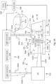
- Fig. 2 schematically depicts an optical-based system 200 for validating an angle between an internal facet of a sample and an external, flat surface of the sample, according to some embodiments.
- System 200 corresponds to specific embodiments of system 100. More specifically, Fig. 2 provides a side-view of system 200 and sample 10 being inspected by system 200, according to some embodiments.
- System 200 includes a LGA 202, and an ICA 204, which correspond to specific embodiments of LGA 102 and ICA 104.
- system 200 may further include an orienting infrastructure 240, a controller 208, and, optionally, a computational module 230.
- Orienting infrastructure 240, controller 208, and computational module 230 correspond to specific embodiments of orienting infrastructure 140, controller 108, and computational module 130, respectively.
- Orienting infrastructure 240 may include a first stage 242 and a second stage 244, which correspond to specific embodiments of first stage 142 and second stage 144, respectively.
- ICA 204 includes an autocollimator 250.
- Autocollimator 250 may be configured to generate a collimated, broad LB 201 in a direction perpendicular to first surface 12a of sample 10.
- a first incident LB 205a and a second incident LB 205b constitute a first sub-beam and a second sub-beam, respectively, of LB 201.
- First incident LB 205a and second incident LB 205b correspond to specific embodiments of first incident LB 105a and second incident LB 105b, respectively.
- Also indicated are a folded LB 213b and an emerged LB 225b, which correspond to specific embodiments of folded LB 113b and emerged LB 125b, respectively.
- LGA 202 includes a LFC 222 and a coupling infrastructure 224, which correspond to specific embodiments of LFC 122 and coupling infrastructure 124, respectively.
- coupling infrastructure 224 includes a CP 232 and a shape-compliant interface 234, which correspond to specific embodiments of CP 132 and shape-compliant interface 134, respectively.
- CP 232 includes a CP first surface 238a, a CP second surface 238b, and a CP third surface 238c, which correspond to specific embodiments of CP first surface 138a, CP second surface 138b, and CP third surface 138c, respectively, of CP 132.
- Additional incident LB 205s may be used to (nominally) orient CP second surface 238b in parallel to internal facet 14. More specifically, additional incident LB 205s may be used to ensure parallelism of a CP first surface 238a of CP 232 and first surface 12a (on which first incident LB 205a normally impinges) of sample 10, since when CP first surface 238a is oriented in parallel to first surface 12a, additional incident LB 205s will normally impinge on CP first surface 238a.
- the orientation of CP first surface 238a may be adjusted (by rotating second stage 244 and/or first stage 242 ) until parallelism thereof relative to first surface 12a is attained.
- CP first surface 238a being disposed in parallel to first surface 12a
- (nominal) parallelism of CP second surface 238b and internal facet 14 may be achieved by rotating CP 232 about an axis parallel to the z -axis.
- optical equipment of ICA 204 may include a pair of blocking elements 256a and 256b, allowing to selectively block each of first incident LB 205a and second incident LB 205b or at least facilitate distinguishing between first returned LB 233a and second returned LB 233b.
- the optical equipment may further include a third blocking element 256s configured to allow selectively blocking additional incident LB 205s or at least facilitate distinguishing additional returned LB 233s from first returned LB 233a and second returned LB 233b.
- each of blocking elements 256a and 256b, and blocking element 256s may be a shutter.
- first surface 12a may be coated, or temporarily coated, by a reflective coating, so that light incident thereon is maximally reflected or reflection therefrom is at least increased.
- CP second surface 238b may be coated by an anti-reflective coating, so that light incident thereon is maximally transmitted into CP 232 or transmission thereto is at least increased.
- CP first surface 238a may be coated by a reflective coating, so that light incident thereon is maximally reflected or reflection therefrom is at least increased.
- first surface 12a may be coated by a first coating configured to reflect light in a first spectrum
- CP second surface 238b may be coated by a coating configured to transmit into CP 232 light in a second spectrum, which differs from the first spectrum, so as to facilitate distinguishing between first returned LB 233a and second returned LB 233b
- internal facet 14 may be configured to reflect light at the second spectrum (and at least partially transmit light in the first spectrum).
- a spectral filter or spectral filter arrangement e.g. included in autocollimator 250 ), configured to allow controllably filtering therethrough light in the first spectrum or the second spectrum, may be employed to facilitate separately sensing each of returned LBs 233.
- CP first surface 238a may be coated by a third coating configured to reflect light in a third spectrum differing from each of the first spectrum and second spectrum, so as to facilitate distinguishing additional returned LB 233s from each of first returned LB 233a and second returned LB 233b.
- the spectral filter or spectral filter arrangement e.g. included in autocollimator 250 ) may be further configured to allow controllably filtering therethrough light in the third spectrum.
- blocking elements 256a and 256b may be (passive) spectral filters (a specific example being dichroic filter) configured to filter therethrough light in the first spectrum and the second spectrum, respectively.
- an additional spectral filter positioned between blocking elements 256 and autocollimator 250 or included in autocollimator 250, and configured to allow selectively filtering therethrough either light in the first spectrum or the second spectrum, may be employed.
- Fig. 3 schematically depicts an optical-based system 300 for validating the angle between an internal facet of a sample and an external, flat surface of the sample, according to some embodiments.
- System 300 corresponds to specific embodiments of system 100, wherein the LFC is or includes a prism. More specifically, Fig. 3 provides a side-view of system 300 and sample 10 being inspected by system 300.
- System 300 includes a LGA 302 and an ICA 304 (components thereof are not shown), which correspond to specific embodiments of LGA 102 and ICA 104.
- system 300 may further include a controller 308, an orienting infrastructure 340, and, optionally, a computational module 330.
- Orienting infrastructure 340, controller 308, and computational module 330 correspond to specific embodiments of orienting infrastructure 140, controller 108, and computational module 130, respectively.
- LGA 302 includes a prism 322 and a coupling infrastructure 324 including a CP 332 and a shape-compliant interface 334.
- Prism 322 corresponds to specific embodiments of LFC 122.
- CP 332 and shape-compliant interface 334 correspond to specific embodiments of CP 332 and shape-compliant interface 134.
- prism 322 may be insensitive to variations in pitch - i.e. rotations about the y -axis - at least across a continuous range of pitch angles.
- prism 322 may be a pentaprism, or a like-function prism - e.g. a prism including an even number of internally reflecting surfaces.
- a pentaprism or a like-function prism - e.g. a prism including an even number of internally reflecting surfaces.
- LGA 302 may include two mirrors, nominally set with respect to one another at the same angle at which the two surfaces of prism 322 (a pentaprism first surface 328a and a pentaprism second surface 328b ), which internally reflect a transmitted portion of second incident LB 305b, are set.
- FIG. 3 Shown in Fig. 3 are a first incident LB 305a, a first returned LB 333a, a second incident LB 305b, a folded LB 313b, a transmitted LB 317b, a reflected LB 321b, an emerged LB 325b, and a second returned LB 333b, which correspond to specific embodiments of first incident LB 105a, first returned LB 133a, second incident LB 105b, folded LB 113b, transmitted LB 117b, reflected LB 121b, emerged LB 125b, and second returned LB 133b, respectively. Also shown in Fig.
- FIG. 3 are the trajectories of second incident LB 305b and emerged LB 325b inside prism 322 after entry thereof thereinto.
- Penetrating portions of emerged LB 325b after refraction into prism 322, after reflection therein, and after two reflections therein, are numbered 329b1, 329b2, and 329b3, respectively.
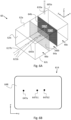
- Figs. 4A-4D present examples of internal facet orientation within samples, according to some embodiments.
- the depicted samples are non-limiting and are intended to illustrate by way of specific examples that system 100 capacity is, in principle, not limited so long as the sample includes: ( i ) an external (first) surface, which is flat; ( ii ) an internal facet set at angle relative to the first surface; and ( iii ) a first part, which is positioned between an external second surface of the sample and the internal facet, which is characterized by a uniform refractive index, and which affords a continuous, straight path for a light beam, transmitted into the sample via the second surface, to normally impinge on the internal facet.
- Sample 40 includes an external, flat first surface 42a, an external second surface 42b, and an internal facet 44. Second surface 42b is positioned opposite to internal facet 44. A first part 46a of sample 40, characterized by a uniform refractive index, is partially bounded by second surface 42b and internal facet 44. Internal facet 44 is nominally inclined at 90° relative to first surface 42a. According to some embodiments, and as depicted in Fig. 4A , second surface 42b may be flat and nominally oriented in parallel to internal facet 44. Sample 40 further includes an external third surface 42c positioned opposite to first surface 42a.
- CP 432 of a system for internal facet metrology of samples, which corresponds to specific embodiments of system 100.
- CP 432 corresponds to specific embodiments of CP 132.
- CP 432 includes an external and flat CP first surface 438a, an external and flat CP second surface 438b, and an external CP third surface (not numbered).
- CP second surface 438b is nominally inclined at the nominal inclination angle relative to CP first surface 438a.
- CP 432 is oriented such that CP first surface 438a is parallel to first surface 42a and CP second surface 438b is nominally parallel to internal facet 44.
- a shape-compliant interface (not shown) may be disposed between the CP third surface and second surface 42b.
- an incident LB is folded by a LFC such as to nominally normally impinge on CP second surface 438b, as described in the description of system 100.
- third surface 42c is flat and parallel to first surface 42a with an uncertainty in the parallelism of third surface 42c and first surface 42a being smaller than a required measurement accuracy of the inclination angle
- the system depicted in Figs. 5A and 5B may be utilized to measure the (actual) inclination angle.
- Sample 40' includes an external, flat first surface 42a', an external second surface 42b', and an internal facet 44'.
- a first part 46a' of sample 40' characterized by a uniform refractive index, is partially bounded by second surface 42b' and internal facet 44'.
- Sample 40' has the same exterior geometry as sample 40 but differs therefrom in an inclination angle (relative to first surface 42a' ) of internal facet 44', which is obtuse. More specifically, the inclination of internal facet 44' differs from that of internal facet 44 by rotation about an axis parallel to the y -axis.
- CP 432' of a system for internal facet metrology of samples, which corresponds to specific embodiments of system 100.
- CP 432' corresponds to specific embodiments of CP 132.
- CP 432' includes an external and flat CP first surface 438a', an external and flat CP second surface 438b', and an external CP third surface (not numbered).
- CP second surface 438b' is nominally inclined at the nominal inclination angle relative to CP first surface 438a'.
- CP 432' is oriented such that CP first surface 438a' is parallel to first surface 42a' and CP second surface 438b' is nominally parallel to internal facet 44'.
- a shape-compliant interface (not shown) may be disposed between the CP third surface and second surface 42b'.
- an incident LB is folded by a LFC such as to nominally normally impinge on CP second surface 438b', as described in the description of system 100.
- Sample 40 includes an external, flat first surface 42a", an external second surface 42b", an external third surface 42c", an external fourth surface 42d", and an internal facet 44" nominally inclined at 90° relative to first surface 42a.
- a first part 46a" of sample 40 characterized by a uniform refractive index, is partially bounded by second surface 42b" and internal facet 44".
- Third surface 42c is positioned opposite to first surface 42a".
- Fourth surface 42d" extends between first surface 42a and second surface 42b and shares a common edge with second surface 42b".
- fourth surface 42d" is flat.
- Sample 40" has the same exterior geometry as sample 40 but differs therefrom in the orientation of internal facet 44". More specifically, the orientation of internal facet 44" differs from that of internal facet 44 by rotation about an axis parallel to the z -axis.
- CP 432" of a system for internal facet metrology of samples, which corresponds to specific embodiments of system 100.
- CP 432 corresponds to specific embodiments of CP 132.
- CP 432" includes an external and flat CP first surface 438a", an external and flat CP second surface 438b", and an external CP third surface (not numbered).
- CP second surface 438b" is nominally inclined at the nominal inclination angle relative to CP first surface 438a”.
- CP 432" is oriented such that CP first surface 438a" is parallel to first surface 42a" and CP second surface 438b" is nominally parallel to internal facet 44".
- a shape-compliant interface (not shown) may be disposed between the CP third surface and second surface 42b".
- an incident LB is folded by a LFC such as to nominally normally impinge on CP second surface 438b", as described in the description of system 100.
- third surface 42c" is flat and parallel to first surface 42a with an uncertainty in the parallelism of third surface 42c" and first surface 42a" being smaller than a required measurement accuracy of the inclination angle
- the system depicted in Figs. 5A and 5B may be utilized to measure the (actual) inclination angle.
- Sample 40′′′ includes an external, flat first surface 42a′′′, an external second surface 42b"', and an internal facet 44′′′.
- a first part 46a′′′ of sample 40"' characterized by a uniform refractive index, is partially bounded by second surface 42b′′′ and internal facet 44"'.
- Sample 40′′′ has the same exterior geometry as sample 40 but differs therefrom in an inclination angle ⁇ (relative to first surface 42a′′′ ) of internal facet 44"', which is obtuse, as well as in an orientation relative to second surface 42b"'.
- the inclination of internal facet 44′′′ differs from that of internal facet 44 by rotation about a first axis parallel to an axis s (indicated in Fig. 4C ), which is positioned on the yz -plane about midway between positive y -axis and the positive z -axis.
- a top edge 48a′′′ of internal facet 44′′′ extends along first surface 42a"'. Also indicated are: ( i ) a straight, dashed first line T 1 , which extends along internal facet 44′′′ and is perpendicular to top edge 48a"', ( ii ) a second straight, dashed second line T 2 , which is perpendicular to first surface 42a′′′ and intersects first line T 1 at top edge 48a"', and ( iii ) a straight, dashed third line T 3 , which extends from first line T 1 to second line T 2 in parallel to first surface 42a′′′ (and is therefore perpendicular to second line T 2 ). Finally, the inclination angle ⁇ is indicated.
- CP 432′′′ of a system for internal facet metrology of samples, which corresponds to specific embodiments of system 100.
- CP 432′′′ corresponds to specific embodiments of CP 132.
- CP 432′′′ includes an external and flat CP first surface 438a"', an external and flat CP second surface 438b"', and an external CP third surface (not numbered).
- CP second surface 438b′′′ is nominally inclined at the nominal inclination angle relative to CP first surface 438a"'.
- CP 432′′′ is oriented such that CP first surface 438a′′′ is parallel to first surface 42a′′′ and CP second surface 438b′′′ is nominally parallel to internal facet 44"'.
- a shape-compliant interface (not shown) may be disposed between the CP third surface and second surface 42b"'.
- an incident LB is folded by a LFC such as to nominally normally impinge on CP second surface 438b"', as described in the description of system 100.
- Figs. 5A and 5B schematically depict an optical-based system 500 for validating perpendicularity of an internal facet of a sample relative to at least two other external and flat surfaces of the sample, which are parallel to one another, according to some embodiments.
- System 500 corresponds to specific embodiments of system 100. More specifically, each of Figs. 5A and 5B presents a respective cross-sectional side-view of system 500 and a sample 50 being inspected by system 500, according to some embodiments.
- Sample 50 includes an external and flat first surface 52a, an external second surface 52b, an external and flat third surface 52c, and an internal facet 54.
- internal facet 14 which constitutes the boundary between, or forms a thin flat layer disposed between, first part 16a and second part 16b of sample 10
- internal facet 54 constitutes the boundary between, or forms a thin flat layer disposed between, a first part 56a and a second part 56b of sample 50.
- First surface 52a and third surface 52c are parallel by design.
- sample 50 is manufactured to exhibit a (nominal) inclination angle of 90° of internal facet 54 relative to first surface 52a (and third surface 52c ).
- ⁇ ' an actual inclination angle of internal facet 52b relative to first surface 52a, labelled in Figs. 5A and 5B as ⁇ ', will generally differ from 90°.
- an actual angle ⁇ ' (also referred to as "the actual supplementary angle") between internal facet 54 and first surface 52a may be taken to equal 180° - ⁇ ', i.e. the supplementary angle to the actual inclination angle ⁇ '. (The nominal value of the actual supplementary angle ⁇ ' is 90°.)
- System 500 includes a LGA 502 and an ICA 504.
- LGA 502 corresponds to specific embodiments of LGA 102 and includes a LFC 522 and a coupling infrastructure 524, which correspond to specific embodiments of LFC 122 and coupling infrastructure 124, respectively.
- LFC 522 is nominally configured to fold by 90° light incident thereon in a direction perpendicular to the nominal inclination of internal facet 54.
- LFC 522 may be a prism, one or more mirrors, or a diffraction grating.
- LFC 522 may be a pentaprism or a like-function prism (i.e. insensitive to variations in pitch) configured to fold light incident thereon by 90°.
- LFC 522 may be a pair of mirrors set at an angle, or a like-function arrangement of mirrors (i.e. insensitive to variations in pitch), configured to fold light incident thereon by 90°.
- coupling infrastructure 524 may include a CP 532 and a shape-compliant interface 534, which correspond to specific embodiments of CP 132 and shape-compliant interface 134, respectively.
- CP 532 includes a CP first surface 538a, a CP second surface 538b, a CP third surface 538c, which correspond to specific embodiments of CP first surface 138a, CP second surface 138b, and CP third surface 138c, respectively.
- CP second surface 538b is nominally perpendicular to CP first surface 538a.
- CP 532 further includes a CP fourth surface 538d, which is positioned opposite to CP first surface 538a. According to some embodiments, and as depicted in Figs. 5A and 5B , CP fourth surface 538d may be parallel to CP first surface 538a.
- system 500 may further include orienting infrastructure 540, which corresponds to specific embodiments of orienting infrastructure 140.
- Orienting infrastructure 540 includes an orientable first stage 542 and an orientable second stage 544, which are configured for placement thereon, and orienting of, sample 50 and CP 532, respectively, essentially as described with respect to first stage 142 and second stage 144 in the description of system 100.
- system 500 may further include a controller 508, and, optionally, a computational module 530, which correspond to specific embodiments of controller 108 and computational module 130, respectively.
- ICA 504 corresponds to specific embodiments of ICA 104 and includes a light source 512, a sensor 514, and, optionally, optical equipment 518, which correspond to specific embodiments of light source 112, sensor 114, and optical equipment 118, respectively.
- light source 512, sensor 514, and some or all of optical equipment 518 may constitute components of an autocollimator, which may be similar to autocollimator 250.
- optical equipment 518 may include blocking elements (not shown), which may be similar to blocking elements 256.
- ICA 504 is configured to output a first incident LB 505a directed at sample 50 and second incident LB 505b is directed at LFC 522.
- ICA 204 and sample 50 are positioned and oriented, such that first incident LB 505a is incident on first surface 52a perpendicularly thereto.
- first incident LB 505a (or at least a portion thereof) is reflected off first surface 52a - as indicated by a first returned LB 533a.
- First returned LB 533a is sensed by sensor 514.
- LFC 522 is configured to nominally fold second incident LB 505b by 90°. More precisely, LFC 522 is configured and oriented to fold second incident LB 505b, such that a (first) folded LB 513b (obtained by the folding of second incident LB 505b ) is nominally directed at 90° relative to second incident LB 505b and (nominally) perpendicularly to CP second surface 538b. In practice, due to manufacturing imperfections (and alignment imprecision in embodiments wherein LFC 522 is sensitive to variations in pitch), an actual light folding angle ⁇ " of LFC 522 may slightly deviate from 90°.
- folded LB 513b is transmitted into CP 532 via CP second surface 538b, as indicated by a (first) transmitted LB 517b.
- Transmitted LB 517 propagates across CP 532, across shape-compliant interface 534, and first part 56a, and impinges on internal facet 54 at a (first) incidence angle ⁇ 1 , essentially as described above with respect to transmitted LB 117b in the description of Fig. 1B .
- a normal to internal facet 54 is indicated in Fig. 5A by a (straight) dashed line C 1 .
- a transmitted LB 517b (or at least a portion thereof) is specularly reflected off internal facet 54 (i.e. at a return angle ⁇ 1 equal to minus the first incidence angle ⁇ 1 ), as indicated by a (first) reflected LB 521b.
- Reflected LB 521b travels back towards LFC 522 via first part 56a, shape-complaint interface 534, and CP 532.
- a (first) emerged LB 525b indicates a (first) portion of reflected LB 521b, which is refracted to the outside CP 532 via CP second surface 538b (unless exactly perpendicularly incident on CP second surface 538, in which case the first portion will maintain the propagation direction thereof; a second portion of reflected LB 521b, specularly reflected by CP second surface 538b inside CP 532, is not shown).
- Emerged LB 525b is folded by LFC 522 at the light folding angle ⁇ ", as indicated by a second returned LB 533b. Second returned LB 533b is sensed by sensor 514.
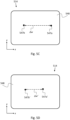
- FIG. 5C schematically depicts a first spot 547a and a second spot 547b formed by first returned LB 533a and second returned LB 533b, respectively, on a photosensitive surface 548 of sensor 514, according to some embodiments.
- w 1 and w 2 are the horizontal coordinates (i.e. as measured along the x-axis) of first spot 547a and second spot 547b, respectively.
- sample 50 has been flipped, such that first surface 52a and third surface 52c are inverted (while maintaining the nominal orientation of internal facet 54 relative to LGA 502 ) and CP 532 has been flipped, such that CP first surface 538a and CP fourth surface 538d are inverted (while maintaining a nominal orientation of CP second surface 538b relative to sample 50 ).
- third incident LB 505a' is directed at sample 50, perpendicularly thereto, and fourth incident LB 505b' is directed at LFC 522.
- Third incident LB 505a' (or at least a portion thereof) is reflected off third surface 52c - as indicated by a third returned LB 533a'.
- Third returned LB 533a' is sensed by sensor 514.
- Fourth incident LB 505b' impinges on LFC 522, resulting in a second folded LB 513b', which in turn impinges on CP second surface 538b, resulting in a second transmitted LB 517b', which propagates across CP 532, across shape-compliant interface 534, and into first part 56a of sample 50.
- Second transmitted LB 517b' impinges on internal facet 54 at a second incidence angle ⁇ 2 .
- a normal to internal facet 54 is indicated in Fig. 5B by a (straight) dashed line C 2 .
- Second transmitted LB 517b' is (at least in part) specularly reflected off internal facet 54 (i.e. at a return angle ⁇ 2 equal to minus the second incidence angle ⁇ 2 ), as indicated by a second reflected LB 521b'.
- Second reflected LB 521b' travels back towards LFC 522 via first part 56a, shape-complaint interface 534, and CP 532.
- a second emerged LB 525b' indicates a portion of second reflected LB 521b', which exits CP 532 via CP second surface 538b (a portion of second reflected LB 521b', internally reflected by CP second surface 538b, is not shown).
- Second emerged LB 525b' is folded by LFC 522 at the light folding angle ⁇ ", as indicated by a fourth returned LB 533b'. Fourth returned LB 533b' is sensed by sensor 514.
- FIG. 5D schematically depicts a third spot 547a' and a fourth spot 547b' formed by third returned LB 533a' and fourth returned LB 533b', respectively, on photosensitive surface 548, according to some embodiments.
- w 1 ' and w 2 ' are the horizontal coordinates of third spot 547a' and fourth spot 547b', respectively.
- ⁇ w and ⁇ w' are both shown as being negative (so that ⁇ 1 and ⁇ 2 are both negative), it is to be understood that generally ⁇ w and ⁇ w' may have opposite signs (so that ⁇ 1 and ⁇ 2 will have opposite signs), or may both be positive (so that ⁇ 1 and ⁇ 2 are both positive).
- Each of the measured angles ⁇ 1 and ⁇ 2 may be used to provide a respective estimate of the deviation angle ⁇ '. Absent any imperfections in system 500, ⁇ 2 would equal - ⁇ 1 and ⁇ 1 would equal - ⁇ 2 . However, in practice, the two estimates will generally differ due to the actual light folding angle deviating from 90° and the actual inclination angle of CP second surface 538b deviating from 90°. Since ⁇ 1 and ⁇ 2 have the same (when the LFC is insensitive to variations in pitch), or substantially the same, dependence on the deviation ⁇ " (i.e.
- the deviation from 90° of the (actual) light folding angle may be cancelled out, or substantially cancelled out, by averaging over the two estimates of the deviation angle ⁇ '.
- ⁇ '> the so-averaged estimate of the actual inclination of internal facet 54
- ⁇ '> the averaged estimate of the deviation of the actual inclination angle from 90°
- ⁇ '> can be shown to equal 90° + ( ⁇ 1 - ⁇ 2 )/(4 n' ) + ⁇ ′′′ ⁇ ( n' - 1)/ n' .
- ⁇ '> may be between 90° + 0.95 ⁇ [( ⁇ 1 - ⁇ 2 )/(4 n ) + ⁇ ′′′ ⁇ ( n - 1)/ n )] and 90° + 1.05 ⁇ [( ⁇ 1 - ⁇ 2 )/(4 n ) + ⁇ ′′′ ⁇ ( n - 1)/ n )], between 90° + 0.9 ⁇ [( ⁇ 1 - ⁇ 2 )/(4 n ) + ⁇ ′′′ ⁇ ( n - 1)/ n )] and 90° + 1.1 ⁇ [( ⁇ 1 - ⁇ 2 )/(4 n ) + ⁇ ′′′ ⁇ ( n - 1)/ n )], or even between 90° + 0.8 ⁇ [( ⁇ 1 - ⁇ 2 )/(4 n ) + ⁇ ′′′ ⁇ ( n - 1)/ n )] and 90° + 1.2 ⁇ [( ⁇ 1 - ⁇ 2 )] and
- ⁇ '> can be shown to equal, or to equal about, 90° + ( ⁇ w - ⁇ w' )/(2 ⁇ f 0 ⁇ n' ) + ⁇ ′′′ ⁇ ( n' - 1)/ n' , wherein f 0 is the focal length of the collimating lens of the autocollimator.
- light source 512 and optical equipment 518 may be configured to produce an expanded (collimated) laser beam or a pair of parallel and spaced-apart (collimated) laser beams, essentially as described above in the description of system 100.
- ICA 504 may be or includes an interferometric setup, as described above in the description of system 100.
- the disclosed systems may also be utilized to obtain information about a plurality of internal facets, which are nominally parallel.
- the information may be collective information and may specify the average (mean) actual inclination angle of the internal facets, or a weighted average of the actual inclination angles, as described below.
- Fig. 6A depicts such a sample, a sample 60, according to some embodiments.
- sample 60 is shown as including two nominally parallel internal facets, but the skilled person will readily appreciate that it is straightforward to apply the teachings of Figs. 6A and 6B to samples including three or more internal facets, which are nominally parallel.
- Sample 60 includes an external, flat first surface 62a, an external second surface 62b, a first internal facet 64a, and a second internal facet 64b.
- Second surface 62b is set at an angle relative to first surface 62a (and may or may not be flat).
- First internal facet 64a is flat and nominally inclined at a nominal inclination angle (not indicated) relative to first surface 62a.
- Second internal facet 64b is flat and nominally parallel to first internal facet 64a.
- First internal facet 64a is positioned between second surface 62b and second internal facet 64b.
- a first part 66a of sample 60 is partially bounded by second surface 62b and first internal facet 64a.
- a second part 66b of sample 60 is partially bounded by first internal facet 64a and second internal facet 64b.
- Second internal facet 64b extends between second part 66b and a third part 66c of sample 60.
- First part 66a and second part 66b have the same refractive index (or close refractive indices).
- First internal facet 64a constitutes a thin layer of material(s) characterized by a refractive index, which differs from that of first part 66a and second part 66b.
- first internal facet 64a and second internal facet 64b relative to first surface 62a may be obtained utilizing any one of systems 100, 200, or 300, essentially as described above in the corresponding descriptions and with additions/adjustments as specified below.
- the nominal inclination angle is 90° and sample 60 includes an external, flat third surface 62c, which is parallel to first surface 62a
- information regarding the actual inclination angles may be obtained utilizing system 500, essentially as described above in the corresponding descriptions and with additions/adjustments as specified below.
- a system (not shown in Fig. 6A ), which corresponds to specific embodiments of system 100, is utilized to inspect sample 60. Indicated is a first incident LB 605a (only a single ray thereof is shown), which is projected on first surface 62a, perpendicularly thereto. A first returned LB 633a is obtained from the reflection of first incident LB 605a off first surface 62a.
- a transmitted LB 617b (only a single ray thereof is shown), which may be obtained by nominally folding (using a LFC of the system (not shown) employed to perform the inspection) a second incident LB at the nominal inclination angle, which is then transmitted into a CP of the system, oriented such that the folded LB is nominally perpendicularly incident on an external, flat surface of the CP, which is nominally parallel to internal facets 64.
- Transmitted LB 617b exits the CP into a shape-compliant interface positioned between the CP and sample 60.
- Each of the CP and the shape-compliant interface are characterized by a refractive index equal to, or at least close to, that of first part 66a and second part 66b of sample 60.
- Transmitted LB 617b enters sample 60 via second surface 62b. Transmitted LB 617b nominally perpendicularly impinges on first internal facet 64a.
- a reflected LB 621b corresponds to the portion of transmitted LB 617b, which is specularly reflected off first internal facet 64a.
- a (first) transmitted portion 637b corresponds to the portion of transmitted LB 617b, which is transmitted into second part 66b. Transmitted portion 637b nominally perpendicularly impinges on second internal facet 64b.
- a reflected portion 641b corresponds to the portion of transmitted portion 637b, which is specularly reflected off second facet 64b.
- a second transmitted portion 645b indicates the portion of reflected portion 641b, which is transmitted back into first part 66a via first internal facet 64a.
- Fig. 6B schematically depicts a first spot 647a and a pair of spots 647b - including a second spot 647b1 and a third spot 647b2 - on a photosensitive surface 648 of a sensor 614 of the system employed to inspect sample 60, according to some embodiments.
- First spot 647a is formed by first returned LB 633a.
- Second spot 647b1 and a third spot 647b2 are formed by the returned LBs induced by reflected LB 621b and second transmitted portion 645b (i.e. by reflection off first internal facet 64a and second internal facet 64b, respectively).
- first returned LB 633a may be discriminated from the returned LBs (not shown) induced by reflected LB 621b and second transmitted portion 645b. If second spot 647b1 (and third spot 647b2 ) cannot be attributed to one of the two returned LBs, induced by reflected LB 621b and second transmitted portion 645b, then only collective information (e.g. average actual inclination) about first internal facet 64a and second internal facet 64b may be extracted from the positions of second spot 647b1 and third spot 647b2 (from the average of the deviation angles of the returned LBs, associated with reflected LB 621b and second transmitted portion 645b, relative to first returned LB 633a ).
- collective information e.g. average actual inclination
- the intensity of the returned LB, associated with reflected LB 621b may be significantly greater than the intensity of the returned LB, associated with second transmitted portion 645b. Accordingly, first spot 647b1 may be attributed to reflected LB 621b or second transmitted portion 645b according to whether the brightness thereof is respectively greater or lesser than that of second spot 647b2 (with the inverse applying for second spot 647b2 ).
- first internal facet 64a is configured to reflect light at a first spectrum and second internal facet 64b is configured to reflect light at a second spectrum.
- the second spectrum sufficiently differs from the first spectrum so as to allow discriminating between the returned LB induced by reflection off first internal facet 64a, and the returned LB induced by the reflection off second internal facet 64b.
- the discrimination may be carried out utilizing a spectral filter, which is configured to selectively filter therethrough light in either of the first and second spectra, as described above in the description of Figs. 1A and 2 . Discrimination between first returned LB 633a and the returned LBs, induced by reflection off internal facets 64, may be similarly carried out.
- sample 60 includes third surface 62c, which is opposite to first surface 62a
- additional collective or individual information regarding the actual inclination angles of internal facets 64 may be obtained by flipping sample 60, such that the first surface 62a and third surface 62c are inverted and an orientation of second surface 62b relative to the LGA, used in performing the measurements, is maintained, and repeating the measurement, essentially as taught above in the description of system 500 and below in the description of the method of Figs. 8A and 8B .
- Method 700 may include:
- the term "obtaining" may be employed both in an active and a passive sense.
- the first returned LB may be obtained not due to any operation implemented in stage 730 but rather due to the generation of the first incident LB in stage 720.
- a stage may describe an active operation performed by a user or by the system used to implement the method, and/or the results or effects of one or more operations performed in one or more earlier stages.
- Method 700 may be implemented employing an optical-based system, such as any one of optical-based systems 100, 200, and 300 or optical-based systems similar thereto, as described above in the respective descriptions thereof.
- method 700 may be autocollimator-based, based on the measurement of distance between laser beams, or may be based on interferometry, as detailed in the description of the various embodiments of system 100.
- the second incident LB may be nominally folded at the nominal inclination angle utilizing any one of LFC 122, LFC 222, and prism 322, or a similar function LFC.
- the second returned LB may be obtained utilizing any one of LFC 122, LFC 222, and prism 322, or a like-function LFC.
- the internal facet may demarcate a flat boundary between a first part (e.g. first part 16a ) and a second part (e.g. second part 16b ) of the sample, which differ in their refractive indices.
- the internal facet may constitute a thin and flat and layer between a first part and a second part of the sample, which has a different refractive index than each of the first part and the second part (whose refractive indices may or may not be the same).
- the first part may extend between the internal facet and an external, flat second surface (e.g. second surface 12b ) of the sample.
- a transmitted LB e.g. transmitted LB 117b
- a transmitted LB which constitutes a portion of second incident LB transmitted into the sample, may enter thereinto via the second surface.
- a collimated light beam such as LB 201
- a collimated light beam may be generated, of which a first sub-beam and a second sub-beam constitute the first incident LB and the second incident LB, respectively.
- the first incident LB and the second incident LB may be adjacent.
- the first incident LB and the second incident LB may form complementary portions of the collimated light beam.
- the first incident LB and the second incident LB may be spaced apart, with a portion of the collimated light beam, which would have been positioned therebetween, having been removed (e.g. blocked, for example, using a light absorbing filter or an opaque plate).
- the collimated light beam may be generated using an autocollimator, such as autocollimator 250.
- the LFC may be configured such that the light folding angle thereof is independent of a pitch angle at which the LFC is set (so that the second incident LB is nominally folded at the nominal inclination angle ⁇ irrespectively of the pitch angle).
- the LFC may be a pentaprism or a like-function prism, or a pair of plane mirrors set at an angle relative to one another, or a like-function mirror arrangement, as described above in the Systems subsection in the description of systems 100 and 300.
- the LGA may include, in addition to the LFC, a coupling infrastructure, such as coupling infrastructure 124.
- the coupling infrastructure is configured to guide light, nominally folded by the LFC (e.g. folded LB 113b ) at the nominal inclination angle, into or onto to the sample, so that the transmitted light (e.g. transmitted LB 117b ) nominally normally impinges on the internal facet.
- the coupling infrastructure may include a coupling prism (CP), such as CP 132, and a shape-compliant interface, such as shape-compliant interface 134.
- CP coupling prism
- shape-compliant interface such as shape-compliant interface 134.
- Each of the CP and the shape-compliant interface may be characterized by refractive indices equal to, or close to equal to, the refractive index of the sample or at least the first part of the sample in embodiments wherein the first part and second part of the sample do not have the same refractive index.
- the CP includes an external and flat first surface (referred to as “CP first surface”), an external and flat second surface (referred to as “CP second surface”), and an external third surface (referred to as “CP third surface”), such as CP first surface 138a, CP second surface 138b, and CP third surface 138c, respectively.
- CP first surface an external and flat first surface
- CP second surface an external and flat second surface
- CP third surface an external third surface
- the shape-complaint interface is disposed between the CP and the first part of the sample, adjacently to each, so as to define a continuum of materials having equal, or close to equal, refractive indices. More specifically, the shape-compliant interface is disposed between the CP third surface and the second surface of the sample with the CP and the sample being mutually aligned, such that the CP second surface and the internal facet of the sample are nominally parallel.
- the forming of a continuum of materials having the same refractive indices, or close refractive indices helps ensure that in stage 740 ( i ) the propagation direction of a light beam transmitted into the CP (e.g. transmitted LB 117b ) is maintained on crossing from the CP into the shape-compliant interface, and, next, on crossing from the shape-compliant interface into the first part of the sample, and (ii) the propagation direction of the light beam reflected off the internal facet (e.g. reflected LB 121b ) is maintained on crossing from the first part of the sample into the shape-compliant interface, and, next, on crossing from the shape-compliant interface into the CP.
- this helps ensure that a transmitted portion (e.g. transmitted LB 117b ) of a light beam (e.g. folded LB 113b ), which is normally incident on the CP second surface, will nominally normally impinge on the internal facet of the sample.
- a folded LB (e.g. folded LB 113b ) - obtained by the folding of the second incident LB by the LFC - impinges on the CP second surface nominally normally thereto and is (at least in part) transmitted into the CP.
- the transmitted LB (e.g. transmitted LB 117b ) continuously travels across the CP, across the shape-compliant interface, and the first part of the sample.
- the transmitted LB nominally normally impinges on the internal facet and is reflected (at least in part) off the internal facet.
- the reflected LB (e.g.
- reflected LB 121b travels back across the first part, the shape-compliant interface, and the CP. At least a portion (e.g. emerged LB 125b ) of the reflected LB emerges from the CP in the direction of the LFC. The LFC nominally folds the emerged LB at the nominal inclination angle, thereby obtaining the second returned LB.
- an additional incident LB (e.g. additional incident LB 205s ) may be projected nominally normally to the CP first surface.
- the additional incident LB may be used to validate that the CP first surface and the first surface of the sample are aligned, for example, by measuring an angular deviation between an additional returned LB (e.g. additional returned LB 233s ), obtained from the reflection of the additional incident LB off the CP first surface, and first returned LB.
- GS samples may be employed as part of the calibration of the system used to implement method 700. More specifically, given a sample to be tested, a corresponding GS sample (i.e. a sample that is known to exhibit the requisite geometry to high precision and has the same refractive index as the sample to be tested) may be employed in calibrating the system.
- the GS sample may be employed to calibrate an orienting infrastructure (e.g. orienting infrastructure 140, orienting infrastructure 240 ) and the LGA, such that ( i ) the first incident will normally impinge on a first surface (analogous to first surface 12a ) of the GS sample and ( ii ) the transmitted LB will (i.e. to a precision afforded by the GS sample and the LGA) perpendicularly impinge on an internal facet (analogous to internal facet 14 ) of the GS sample.
- an orienting infrastructure e.g. orienting infrastructure 140, orienting infrastructure 240
- the LGA
- a (first) orientable stage (e.g. stage 142 ), on which the sample may be mounted, may be used to orient the GS sample relative to each of the LGA, as a whole or relative a single component thereof (for example, the CP), and the ICA. Additionally, or alternatively, a second orientable stage (e.g. second stage 144 ) may be used to orient the CP relative to the GS sample and the LFC.
- An autocollimator whether part of the ICA (in embodiments wherein the system includes an autocollimator), or not included in the system, may be used to validate the perpendicularity of the transmitted LB.
- Calibration or additional calibration may be performed after stage 710, once the sample to be tested has been provided and disposed e.g. on the orientable stage.
- the additional calibration may include, for example, orienting or re-orienting the orientable stage, on which the sample to be tested is mounted, such that the first incident LB perpendicularly impinges on the first surface of the sample to be tested.
- an autocollimator e.g. autocollimator 250, and, more generally, in embodiments wherein an autocollimator is used in preparing the incident LBs, that same autocollimator
- Blocking elements such as shutters and/or spectral filters may be employed to selectively block (or at least partially block) each of the returned LBs, essentially as described above in the description of systems 100 and 200.
- Blocking elements such as shutters and/or spectral filters may be employed to selectively block (or at least partially block) each of the returned LBs, essentially as described above in the description of systems 100 and 200.
- the blocking of one returned LB, while sensing the other returned LB may serve to increase measurement precision by attenuating the signal associated with stray light.
- stages 710, 720, and 730 are implemented employing an autocollimator, such as autocollimator 250
- ⁇ 1 and ⁇ 2 are the horizontal coordinates of a first spot (e.g. first spot 247a ) and a second spot formed (e.g. second spot 247b ) on the photosensitive surface (e.g. photosensitive surface 248 ) of the autocollimator by the first returned LB and the second returned LB, respectively.
- f ⁇ is the focal length of a collimating lens of the autocollimator.
- the actual inclination angle ⁇ ' may be computed using the laws of geometrical optics and, in particular, Snell's law (and taking into account the actual light folding angle of the LFC, the actual inclination angle of the CP second surface relative to the CP first surface, and the value of refractive index of the first part of the sample).
- the sample e.g. sample 60
- the sample includes a plurality of internal facets (e.g. internal facets 64 ), nominally perpendicular to the first surface, and, except for the internal facets, the sample is further characterized by a uniform or close to uniform refractive index, in stage 740, a plurality of returned LBs is obtained by redirection by the LGA of the second incident LB into or onto the sample, reflection thereof off each of the internal facets, and inverse redirection by the LGA, essentially as described in the description of Figs . 6A and 6B .
- a plurality of angular deviations of each of the plurality of returned LBs relative to the first returned LB is measured by sensing the first returned LB and each of the plurality of returned LBs.
- actual inclination angles of each of the plurality of internal facets relative to the first surface may be deduced based at least on the plurality of measured angular deviations.
- Each of the spots, formed by the plurality of returned LBs on a photosensitive surface of a sensor may be attributed to a respective one of the plurality of returned LBs based on relative brightness of the spots, and/or - wherein each of the internal facets is configured to reflect light at a respective distinct spectrum - employing spectral filters. Additionally, or alternatively, collective information regarding the actual inclination angles (such as the mean actual inclination angle) is deduced based at least on the plurality of measured angular deviations.
- Figs. 8A and 8B present a flowchart of an optical-based method 800 for metrology of internal facets of samples, which is not covered by the claims.
- Method 800 corresponds to specific aspects of method 700 and may be employed to validate perpendicularity of one or more internal facets of a sample relative to at least two external and flat surfaces of the sample, which are parallel to one another.
- Method 800 may include:
- Method 800 may be implemented employing an optical-based system, such as optical-based system 500 or an optical-based system similar thereto, as described above in the description of Figs. 5A-5D .
- method 800 may be autocollimator-based, based on the measurement of distance between laser beams, or based on interferometry.
- the first folded LB and the second returned LB may be obtained from the second incident LB and the first reflected LB, respectively, utilizing a LFC configured to nominally fold by 90° light incident thereon, such as LFC 522 or a like-function LFC.
- the LFC may be or include a prism (e.g. a pentaprism) configured to fold light by 90°, or one or more mirrors (jointly) configured to fold light by 90°.
- the second folded LB and the fourth returned LB may be obtained from the fourth incident LB and the second reflected LB, respectively, utilizing LFC 522 or a like-function LFC.
- the LGA may include, in addition to the LFC, a coupling infrastructure, such as coupling infrastructure 524.
- the coupling infrastructure is configured to guide light, folded by the LFC (e.g. folded LB 513b ), into or onto to the sample, so that the transmitted light (e.g. transmitted LB 517b ) nominally normally impinges on the internal facet.
- the coupling infrastructure may include a coupling prism (CP), such as CP 532, and a shape-compliant interface, such as shape-compliant interface 534.
- CP coupling prism
- shape-compliant interface such as shape-compliant interface 534.
- Each of the CP and the shape-compliant interface are characterized by a respective refractive index equal to, or close to equal to, that of the sample or at least the first part of the sample in embodiments wherein the first part and second part of the sample do not have the same refractive index.
- the CP includes an external and flat first surface (referred to as “CP first surface”), an external and flat second surface (referred to as “CP second surface”), and an external third surface (referred to as “CP third surface”), such as CP first surface 538a, CP second surface 538b, and CP third surface 538c, respectively.
- CP first surface an external and flat first surface
- CP second surface an external and flat second surface
- CP third surface an external third surface
- the CP includes an external and flat fourth surface (referred to "CP fourth surface"), such as CP fourth surface 538d.
- the CP fourth surface is opposite and parallel to the CP first surface.
- the CP may also be flipped, such that the CP first surface and the CP fourth surface, with a nominal orientation of the CP second surface (through which the light, folded by the LFC, enters into the CP) relative to the internal facet being maintained.
- an autocollimator e.g. autocollimator
- an autocollimator e.g. the autocollimator used in preparing the incident LBs
- an autocollimator e.g. the autocollimator used in preparing the incident LBs
- Shutters and/or spectral filters may be employed to selectively block (or at least partially block) one of the second returned LB and the first returned LB, and one of the fourth returned LB and the third returned LB, essentially as described above in the description of Figs. 5A and 5B .
- Method 800 may include an optional calibration stage (not shown in Figs. 8A and 8B ) similar to stage 705 of method 700, and which is (partially) repeated after flipping the sample in stage 830 (and performed before stages 835 to 855 ). More specifically, in stage 830, after the sample is flipped, the orientation of the sample may be reoriented, such that light transmitted into the sample is incident on the internal facet nominally perpendicularly thereto. In embodiments, wherein the CP is also flipped, the CP may also be reoriented, such that light folded by the LFC (e.g. second folded LB 513b ') will nominally perpendicularly impinge on the CP second surface.
- the LFC e.g. second folded LB 513b '
- w ⁇ 1 and w ⁇ 2 are the horizontal coordinates of a first spot and a second spot (e.g. first spot 547a and second spot 547b ) formed on the photosensitive surface (e.g. photosensitive surface 548 ) of the autocollimator by the first returned LB and the second returned LB, respectively.
- f ⁇ 0 is the focal length of a collimating lens of the autocollimator.
- w ⁇ 1 ′ and w ⁇ 2 ' are the horizontal coordinates of a third spot and a fourth spot (e.g. third spot 547a' and fourth spot 547b' ) formed on the photosensitive surface of the autocollimator by the third returned LB and the fourth returned LB, respectively.
- ⁇ ' is the refractive index of the first part of the sample (as well as the CP and the shape-compliant interface or is at least close to the respective refractive indices thereof).
- the sample e.g. sample 60
- the sample includes a plurality of internal facets (e.g. internal facets 64 ), nominally perpendicular to the first surface, and, except for the internal facets, the sample is further characterized by a uniform or close to uniform refractive index, in stage 820 , a first plurality of returned LBs is obtained by redirection by the LGA of the second incident LB into or onto the sample, reflection thereof off each of the internal facets, and inverse redirection by the LGA, essentially as described in the description of Figs. 6A and 6B .
- a first plurality of angular deviations of each of the first plurality of returned LBs relative to the first returned LB is measured by sensing the first returned LB and each of the first plurality of returned LBs.
- a second plurality of returned LBs is obtained by redirection by the LGA of the fourth incident LB into or onto the sample, reflection thereof off each of the internal facets, and inverse redirection by the LGA.
- a second plurality of angular deviations of each of the second plurality of returned LBs relative to the third returned LB is measured by sensing the third returned LB and each of the second plurality of returned LBs.
- actual inclination angles of each of the plurality of internal facets relative to the first surface may be deduced based on the first plurality of measured angular deviations and the second plurality of measured angular deviations.
- Each of the spots formed by the plurality of returned LBs may be attributed to a respective one of the plurality of returned LBs based on relative brightness of the spots, and/or - wherein each of the internal facets is configured to reflect light at a respective distinct spectrum - employing spectral filters.
- collective information regarding the actual inclination angles (such as the mean actual inclination angle) is deduced based at on the first and second pluralities of measured angular deviations.
- method 800 may additionally include four measurements instead: a first measurement with both the sample and the CP unflipped, a second measurement with the sample unflipped and the CP flipped, a third measurement with both the sample and the CP flipped, and a fourth measurement with the sample flipped and the CP unflipped.
- the four measurements may increase measurement precession by effectively canceling out the contribution of ⁇ ′′′ to ⁇ ' ⁇ .
- a non-limiting example of such a sample is sample 40 in Fig. 4A , wherein sample 40 further comprises an external and flat surface opposite to first surface 42a.
- Fig. 9 schematically depicts an optical-based system 900 for internal facet metrology of samples
- System 900 is similar to system 100 but unlike some embodiments of system 100, does not include any coupling infrastructure (such as coupling infrastructure 124 ).
- System 900 is configured for use with samples including at least two external and flat surfaces and an internal facet, which is nominally inclined at a nominal inclination angle relative to a first of the two surfaces.
- samples including at least two external and flat surfaces and an internal facet, which is nominally inclined at a nominal inclination angle relative to a first of the two surfaces.
- Such a sample, a sample 90 is depicted in Fig. 9 , according to some embodiments.
- Sample 90 includes an external, flat first surface 92a, and external, flat second surface 92b, and an internal facet 94.
- Internal facet 94 is nominally inclined at a nominal inclination angle ⁇ relative to first surface 92a.
- Sample 90 is shown being inspected by system 900.
- System 900 includes an ICA 904 and a LFC 922, which may correspond to specific embodiments of ICA 104 and LFC 122, respectively.
- ICA 904 may include a light source, at least one sensor, and, optionally, optical equipment (all not shown), which may correspond to specific embodiments of light source 112, at least one sensor 114, and optical equipment 118, respectively.
- System 900 may further include a controller, an orientable stage, and a computational module (all not shown), which may correspond to specific embodiments of controller 108, first stage 142, and computational module 130.
- the controller may be functionally associated with ICA 904 components, the stage, and the computational module in a similar manner to controller 108 functional association with ICA 104 components, first stage 142, and computational module 130, respectively.
- ICA 904 In operation, ICA 904 generates a pair of incident LBs: a first incident LB 905a and a second incident LB 905b, which is parallel to first incident LB 905a.
- First incident LB 905a is projected nominally normally to first surface 92a.
- a first returned LB 933a is obtained by reflection of first incident LB 905a off first surface 92a and is sensed by a sensor (not shown) of ICA 904.
- Second incident LB 905b is folded by LFC 922, as indicated by a folded LB 913b.
- Folded LB 913b impinges on second surface 92b.
- a transmitted LB 917b indicates a portion of folded LB 913b, which is transmitted into sample 90.
- Transmitted LB 917b nominally normally impinges on internal facet 94. That is, a nominal folding angle of LFC 922 and an orientation of sample 90 relative to LFC 922 are selected such that transmitted LB 917b will nominally normally impinge on internal facet 94.
- a reflected LB 921b indicates a portion of transmitted LB 917b, which is specularly reflected off internal facet 94.
- An emerged LB 925b indicates a portion of reflected LB 921b, which exits sample 90 by refraction via second surface 92b.
- Second returned LB 933b is obtained by the folding of emerged LB 925b by LFC 922. Second returned LB 933b is sensed by the sensor of ICA 904.
- the angular deviation of second returned LB 933b relative to first returned LB 933a may be obtained from the horizontal distance between a second spot and a first spot formed by second returned LB 933b and first returned LB 933a, respectively, on the photosensitive surface of the sensor, as described above in the descriptions of system 100 and method 700. From the measured value of the angular deviation, a deviation in the (actual) inclination of internal facet 94 from the nominal inclination thereof may be derived, essentially as described in the descriptions of system 100 and method 700.
- Fig. 10 schematically depicts an optical-based system 1100 for internal facet metrology of samples, according to some embodiments,
- System 1100 is configured for use with samples including an external and flat surface and an internal facet, which is nominally inclined at a nominal inclination angle relative to the surface.
- samples including an external and flat surface and an internal facet, which is nominally inclined at a nominal inclination angle relative to the surface.
- Sample 1010 includes an external, flat (first) surface 1012a and an internal facet 1014.
- Internal facet 1014 is nominally inclined at a nominal inclination angle ⁇ ' relative to first surface 1012a.
- Sample 1010 is shown being inspected by system 1100.
- System 1100 includes an ICA 1104 and a LFC 1122, which may be similar to ICA 104 and LFC 122, respectively, but differ therefrom as described below.
- ICA 1104 may include a light source, at least one sensor, and, optionally, optical equipment (all not shown), which may be similar to light source 112, at least one sensor 114, and optical equipment 118, respectively.
- System 1100 may further include a controller and a computational module (all not shown), which may correspond to specific embodiments of controller 108 and computational module 130.
- the controller may be functionally associated with ICA 1104 components and the computational module in a similar manner to controller 108 functional association with ICA 104 components and computational module 130, respectively.
- System 1100 may further include an orientable stage (not shown), which may be similar to first stage 142, and which may be controlled by the controller.
- ICA 1104 In operation, ICA 1104 generates a pair of incident LBs: a first incident LB 1105a and a second incident LB 1105b, which is parallel to first incident LB 1105a.
- First incident LB 1105a is projected nominally normally to first surface 1012a.
- a first returned LB 1133a is obtained by reflection of first incident LB 1105a off first surface 1012a and is sensed by a sensor (not shown) of ICA 1104.
- Second incident LB 1105b is folded by LFC 1122, as indicated by a folded LB 1113b.
- Folded LB 1113b impinges on first surface 1012a.
- a transmitted LB 1117b indicates a portion of folded LB 1113b, which is refracted into sample 1000.
- Transmitted LB 1117b nominally normally impinges on internal facet 1014. That is, a nominal folding angle of LFC 1122 and an orientation of sample 1000 relative to LFC 1122 are selected such that transmitted LB 1117b will nominally normally impinge on internal facet 1014.
- a reflected LB 1121b indicates a portion of transmitted LB 1117b, which is specularly reflected off internal facet 1014.
- An emerged LB 1125b indicates a portion of reflected LB 1121b, which exits sample 1000 by refraction via first surface 1012a.
- Second returned LB 1133b is obtained by the folding of emerged LB 1125b by LFC 1122. Second returned LB 1133b is sensed by the sensor of ICA 1104.
- the angular deviation of second returned LB 1133b relative to first returned LB 1133a may be obtained from the horizontal distance between a second spot and a first spot formed by second returned LB 1133b and first returned LB 1133a, respectively, on the photosensitive surface of the sensor, as described above in the descriptions of system 100 and method 700. From the measured value of the angular deviation, a deviation in the (actual) inclination of internal facet 1014 from the nominal inclination thereof may be derived, in a similar manner to the derivation of the actual inclination angle ⁇ ' from the angular deviation ⁇ (described above in the description of system 100 and method 700 ).
- the nominal folding angle of LFC 1122 may be selected such that an intensity of second returned LB 1133b is maximized.
Landscapes
- Physics & Mathematics (AREA)
- General Physics & Mathematics (AREA)
- Chemical & Material Sciences (AREA)
- Analytical Chemistry (AREA)
- Optics & Photonics (AREA)
- Engineering & Computer Science (AREA)
- Radar, Positioning & Navigation (AREA)
- Remote Sensing (AREA)
- Geometry (AREA)
- Life Sciences & Earth Sciences (AREA)
- Biochemistry (AREA)
- General Health & Medical Sciences (AREA)
- Immunology (AREA)
- Pathology (AREA)
- Health & Medical Sciences (AREA)
- Investigating Or Analysing Materials By Optical Means (AREA)
- Length Measuring Devices By Optical Means (AREA)
- Testing Of Optical Devices Or Fibers (AREA)
- Mounting And Adjusting Of Optical Elements (AREA)
- Investigating Materials By The Use Of Optical Means Adapted For Particular Applications (AREA)
- Optical Elements Other Than Lenses (AREA)
- Testing Of Coins (AREA)
- Dental Tools And Instruments Or Auxiliary Dental Instruments (AREA)
Claims (14)
- Optisches System (100, 200, 300, 500), das konfiguriert ist, um eine Ausrichtung einer inneren Facette einer Probe relativ zu einer äußeren, flachen ersten Oberfläche der Probe zu validieren, wobei die Probe einen ersten Teil und einen zweiten Teil umfasst, zwischen denen sich die innere Facette erstreckt, wobei der erste Teil zwischen einer äußeren zweiten Oberfläche der Probe und der inneren Facette positioniert ist, das System umfassend:eine Lichtführungsanordnung, LGA (102, 202, 302, 502), die konfiguriert ist, um Licht, das auf die LGA (102, 202, 302, 502) in einer Richtung senkrecht zu einer äußeren und flachen ersten Oberfläche der Probe auf die Probe zu lenken, sodass das dadurch in die Probe übertragene Licht auf eine innere Facette der Probe trifft, und zwar normalerweise auf die innere Facette;eine Beleuchtungs- und Sammelanordnung, ICA (104, 204, 304, 504), umfassend:eine Lichterzeugungsgruppe, die konfiguriert ist, um (a) einen ersten einfallenden Lichtstrahl, LB, auf die erste Oberfläche zu projizieren, um so einen ersten zurückkehrenden LB durch Reflexion von der ersten Oberfläche zu erzeugen, und (b) einen zweiten einfallenden LB auf die LGA (102, 202, 302, 502) zu projizieren, parallel zum ersten einfallenden LB zu projizieren, um so einen zweiten zurückkehrenden LB zu erzeugen, und zwar durch Umlenkung des zweiten einfallenden LB in oder auf die Probe durch die LGA (102, 202, 302, 502), Reflexion desselben an der inneren Facette und umgekehrte Umlenkung durch die LGA (102, 202, 302, 502); wobei die LGA (102, 202, 302, 502) konfiguriert ist, um die zweite einfallende LB über die zweite Oberfläche in oder auf den ersten Teil der Probe umzulenken; undmindestens einen Sensor (114, 514), der konfiguriert ist, um eine erste Winkelabweichung des zweiten zurückgegebenen LB relativ zum ersten zurückgegebenen LB zu messen, und/oder eine Okularbaugruppe, die konfiguriert ist, um eine manuelle Messung der ersten Winkelabweichung zu ermöglichen;wobei die gemessene erste Winkelabweichung einen tatsächlichen Neigungswinkel der inneren Facette relativ zur ersten Oberfläche angibt.
- Optisches System nach Anspruch 1, wobei die LGA (102, 202, 302, 502) eine Lichtfaltungskomponente LFC (122, 222, 322, 522) umfasst, die nominell so konfiguriert ist, dass sie Licht mindestens dann, wenn es auf sie in einer Richtung senkrecht zur ersten Oberfläche projiziert wird, in einem Lichtfaltungswinkel faltet, der gleich dem nominellen Neigungswinkel ist; und wobei die LFC ein Prisma, einen oder mehrere Spiegel und/oder ein Beugungsgitter umfasst.
- Optisches System nach Anspruch 2, wobei der Lichtfaltungswinkel der LFC unempfindlich gegenüber Änderungen der Neigung der LFC ist; und
wobei die LFC ein Pentaprisma (322) oder ein Prisma mit ähnlicher Funktion oder ein Paar von in einem Winkel zueinander eingestellten Spiegeln oder eine Spiegelanordnung mit ähnlicher Funktion ist oder umfasst. - Optisches System nach Anspruch 2, wobei die LGA (102, 202, 302, 502) ferner eine Kopplungsinfrastruktur (124, 224, 324, 524) umfasst, die so konfiguriert ist, dass sie das von der LFC gefaltete Licht auf oder in die Probe leitet, sodass das dadurch in die Probe übertragene Licht nominell normalerweise auf die innere Facette auftrifft.
- Optisches System nach Anspruch 4, wobei die Kopplungsinfrastruktur ein Kopplungsprisma CP (132, 232, 332, 532) umfasst, das eine äußere, flache erste CP-Oberfläche (138a, 238a, 338a, 538a), eine äußere, flache zweite CP-Oberfläche (138b, 238b, 338b, 538b), die nominell um den Nennwinkel relativ zur ersten CP-Oberfläche geneigt ist, und eine äußere dritte CP-Oberfläche (138c, 238c, 338c, 538c) gegenüber der zweiten CP-Oberfläche umfasst;wobei der CP den gleichen Brechungsindex wie der erste Teil der Probe oder einen nahe daran liegenden Brechungsindex aufweist;wobei der CP so angeordnet ist, dass die erste Oberfläche des CP parallel zu der ersten Oberfläche der Probe verläuft, und ferner so angeordnet ist, dass das durch die LFC gefaltete Licht normalerweise auf die zweite Oberfläche des CP auftrifft; undwobei die Kopplungsinfrastruktur ferner eine formbeständige Schnittstelle (134, 234, 334, 534) umfasst, die zwischen der dritten Oberfläche des CP und der Probe angeordnet ist, sodass die erste Oberfläche des CP parallel zu der ersten Oberfläche der Probe verläuft, wobei die formbeständige Schnittstelle denselben Brechungsindex wie der erste Teil der Probe oder einen nahe daran liegenden Brechungsindex aufweist.
- Optisches System nach Anspruch 1, wobei die Probe ein Prisma oder ein Wellenleiter ist.
- Optisches System nach Anspruch 5, wobei das System ferner eine Ausrichtungsinfrastruktur (140, 240, 340, 540) umfasst, die so konfiguriert ist, dass sie die Probe so ausrichtet, dass der zuerst einfallende LB normalerweise auf die erste Oberfläche auftrifft und/oder ein gefalteter LB, der durch Falten des zweiten einfallenden LB durch die LFC erhalten wird, nominell normalerweise auf die zweite CP-Oberfläche auftrifft.
- Optisches System nach einem der Ansprüche 1 bis 7, umfassend den mindestens einen Sensor, wobei der mindestens eine Sensor einen oder mehrere Lichtsensoren und/oder einen oder mehrere Bildsensoren umfasst; und
wobei die Lichterzeugungsgruppe eine Lichtquelle (112) und eine optische Ausrüstung (118) umfasst, wobei die Lichtquelle konfiguriert ist, um einen einzelnen LB zu erzeugen, und wobei die optische Ausrüstung konfiguriert ist, um den einzelnen LB zu kollimieren. - Optisches System nach Anspruch 8, wobei der erste einfallende LB und der zweite einfallende LB komplementäre Abschnitte des kollimierten LB sind.
- Optisches System nach Anspruch 8, ferner umfassend einen Autokollimator (250), wobei der Autokollimator die Lichtquelle, den mindestens einen Sensor und eine Kollimationslinse oder Kollimationslinsenanordnung umfasst.
- Optisches System nach Anspruch 1, wobei die ICA (104, 204, 304, 504) ferner mindestens zwei Blenden (256a, 256b) umfasst, die so konfiguriert sind, dass sie jeden der einfallenden LBs selektiv blockieren, und/oder einen oder mehrere Spektralfilter (256a, 256b), die so konfiguriert sind, dass sie mindestens die Unterscheidung zwischen den zurückgegebenen LBs erleichtern.
- Optisches System nach Anspruch 7, umfassend den mindestens einen Sensor, wobei das System ferner ein Berechnungsmodul (130, 230, 330, 530) umfasst, das so konfiguriert ist, dass es den tatsächlichen Neigungswinkel mindestens basierend auf der gemessenen ersten Winkelabweichung berechnet.
- Optisches System nach Anspruch 12, wobei die Probe ferner eine äußere, flache dritte Oberfläche umfasst, die parallel zu der ersten Oberfläche ist, wobei das Berechnungsmodul (530) konfiguriert ist, um den tatsächlichen Neigungswinkel zu berechnen, wobei zusätzlich eine gemessene zweite Winkelabweichung eines vierten zurückgeworfenen LB relativ zu einem dritten zurückgeworfenen LB berücksichtigt wird, der erhalten wird, indem die Probe umgedreht wird, sodass die erste Oberfläche und die dritte Oberfläche invertiert sind, (a') Projizieren eines dritten einfallenden Lichtstrahls auf die dritte Oberfläche der Probe, um den dritten zurückgeworfenen LB durch Reflexion an der dritten Oberfläche zu erzeugen, und (b') Projizieren eines vierten einfallenden LB auf die LFC (522) parallel zu dem dritten einfallenden LB, um den vierten zurückgeworfenen LB durch Umlenkung des vierten einfallenden LB in oder auf die Probe durch die LGA (502), Reflexion desselben an der inneren Facette und umgekehrte Umlenkung durch die LGA (502) zu erzeugen.
- Optisches System nach Anspruch 13, wobei der CP (532) ferner eine äußere, flache vierte CP-Oberfläche (538d) umfasst, die parallel zur ersten CP-Oberfläche verläuft, wobei der CP mechanisch kippbar ist, sodass die erste CP-Oberfläche und die vierte CP-Oberfläche invertierbar sind, während eine nominale Ausrichtung der zweiten CP-Oberfläche relativ zur Probe beibehalten wird; und
wobei die gemessene zweite Winkelabweichung mit umgedrehtem CP erhalten wird, sodass die erste Oberfläche des CP und die vierte Oberfläche des CP invertiert sind und die nominale Ausrichtung der zweiten Oberfläche des CP relativ zur Probe beibehalten wird.
Priority Applications (1)
| Application Number | Priority Date | Filing Date | Title |
|---|---|---|---|
| EP25157343.2A EP4542285A3 (de) | 2020-11-18 | 2021-11-18 | Optische validierung von ausrichtungen von internen facetten |
Applications Claiming Priority (2)
| Application Number | Priority Date | Filing Date | Title |
|---|---|---|---|
| US202063115151P | 2020-11-18 | 2020-11-18 | |
| PCT/IL2021/051378 WO2022107141A1 (en) | 2020-11-18 | 2021-11-18 | Optical-based validation of orientations of internal facets |
Related Child Applications (1)
| Application Number | Title | Priority Date | Filing Date |
|---|---|---|---|
| EP25157343.2A Division EP4542285A3 (de) | 2020-11-18 | 2021-11-18 | Optische validierung von ausrichtungen von internen facetten |
Publications (3)
| Publication Number | Publication Date |
|---|---|
| EP4248172A1 EP4248172A1 (de) | 2023-09-27 |
| EP4248172A4 EP4248172A4 (de) | 2024-05-15 |
| EP4248172B1 true EP4248172B1 (de) | 2025-02-19 |
Family
ID=81708635
Family Applications (2)
| Application Number | Title | Priority Date | Filing Date |
|---|---|---|---|
| EP21894198.7A Active EP4248172B1 (de) | 2020-11-18 | 2021-11-18 | Optische validierung von ausrichtungen von internen facetten |
| EP25157343.2A Pending EP4542285A3 (de) | 2020-11-18 | 2021-11-18 | Optische validierung von ausrichtungen von internen facetten |
Family Applications After (1)
| Application Number | Title | Priority Date | Filing Date |
|---|---|---|---|
| EP25157343.2A Pending EP4542285A3 (de) | 2020-11-18 | 2021-11-18 | Optische validierung von ausrichtungen von internen facetten |
Country Status (8)
| Country | Link |
|---|---|
| US (3) | US11747137B2 (de) |
| EP (2) | EP4248172B1 (de) |
| JP (2) | JP7440983B2 (de) |
| KR (2) | KR20240154688A (de) |
| CN (2) | CN116235026B (de) |
| IL (2) | IL302581B2 (de) |
| TW (3) | TW202542491A (de) |
| WO (1) | WO2022107141A1 (de) |
Families Citing this family (4)
| Publication number | Priority date | Publication date | Assignee | Title |
|---|---|---|---|---|
| EP4248172B1 (de) * | 2020-11-18 | 2025-02-19 | Lumus Ltd. | Optische validierung von ausrichtungen von internen facetten |
| CN117730238A (zh) | 2021-07-26 | 2024-03-19 | 鲁姆斯有限公司 | 内部小平面之间的平行度的基于光学的验证 |
| JP2024537590A (ja) * | 2021-07-26 | 2024-10-16 | ルーマス リミテッド | 内部ファセット間の平行性を検証するための方法及びシステム |
| KR20250043403A (ko) | 2022-08-01 | 2025-03-28 | 루머스 리미티드 | 도광 광학 요소의 검사를 위한 신규한 기술 |
Family Cites Families (102)
| Publication number | Priority date | Publication date | Assignee | Title |
|---|---|---|---|---|
| CH563945A5 (de) | 1971-10-20 | 1975-07-15 | Balzers Patent Beteilig Ag | |
| US3969023A (en) | 1975-03-06 | 1976-07-13 | American Optical Corporation | Method and apparatus for detecting layers of stress in lenses |
| JPS61184438A (ja) * | 1985-02-12 | 1986-08-18 | Matsushita Electric Ind Co Ltd | プリズム検査装置 |
| US4720189A (en) | 1986-01-07 | 1988-01-19 | Northern Telecom Limited | Eye-position sensor |
| JP2913984B2 (ja) * | 1992-03-11 | 1999-06-28 | 株式会社ニコン | 傾斜角測定装置 |
| US5220397A (en) * | 1992-03-25 | 1993-06-15 | Peisen Huang | Method and apparatus for angle measurement based on the internal reflection effect |
| US5461472A (en) * | 1993-06-28 | 1995-10-24 | At&T Ipm Corp. | Method and apparatus for measuring the parallelism of two surfaces |
| US5774096A (en) | 1994-04-21 | 1998-06-30 | Kabushiki Kaisha Sega Enterprises | Head mounted display |
| JPH09304036A (ja) * | 1996-05-20 | 1997-11-28 | Sony Corp | 立体部品の角度測定装置 |
| EP0982581B1 (de) | 1998-08-28 | 2005-04-20 | Perkin-Elmer Limited | Datenerfassung für die Spektroskopie |
| JP3913407B2 (ja) | 1999-07-09 | 2007-05-09 | 株式会社リコー | 屈折率分布の測定装置及び方法 |
| AU6147201A (en) | 2000-05-16 | 2001-11-26 | Du Pont | Aqueous dispersions for color imaging |
| JP2004510129A (ja) * | 2000-05-17 | 2004-04-02 | ザイゴ コーポレイション | 干渉装置および干渉方法 |
| CN100507636C (zh) | 2000-06-05 | 2009-07-01 | 鲁姆斯有限公司 | 基片导引的光束扩展器 |
| TW509781B (en) * | 2001-05-10 | 2002-11-11 | Uconn Technology Inc | Measurement method and device of the slanting surface angle of optical device |
| BE1014212A3 (nl) * | 2001-06-05 | 2003-06-03 | Wetenschappelijk En Tech Onder | Werkwijze en inrichting voor het bepalen van de hoek tussen facetten van een transparant object. |
| US20020186179A1 (en) | 2001-06-07 | 2002-12-12 | Knowles Gary R. | Optical display device |
| JP2003065739A (ja) | 2001-08-24 | 2003-03-05 | Koodotekku:Kk | ポリゴンミラー角度計測装置 |
| JP3931605B2 (ja) * | 2001-09-19 | 2007-06-20 | セイコーエプソン株式会社 | 光学素子の検査装置および光学素子の検査方法 |
| JP2003232623A (ja) * | 2002-02-13 | 2003-08-22 | Namiki Precision Jewel Co Ltd | 非接触式平行度測定装置 |
| JP2003279337A (ja) * | 2002-03-20 | 2003-10-02 | Olympus Optical Co Ltd | 偏向角検出装置、光信号スイッチシステム、情報記録再生システム、偏向角検出方法および光信号スイッチング方法 |
| US20070165192A1 (en) | 2006-01-13 | 2007-07-19 | Silicon Optix Inc. | Reduced field angle projection display system |
| US7221452B2 (en) * | 2002-08-07 | 2007-05-22 | Coherent, Inc. | Tunable optical filter, optical apparatus for use therewith and method utilizing same |
| JP4111074B2 (ja) | 2002-08-20 | 2008-07-02 | セイコーエプソン株式会社 | プロジェクタ |
| US6879443B2 (en) | 2003-04-25 | 2005-04-12 | The Microoptical Corporation | Binocular viewing system |
| EP1484596A1 (de) | 2003-06-05 | 2004-12-08 | Fraunhofer-Gesellschaft zur Förderung der angewandten Forschung e.V. | Verfahren und Vorrichtung zur dreidimensionalen Bestimmung des Brechungsindex von transparenten Schichten |
| US7362447B2 (en) * | 2004-02-20 | 2008-04-22 | Agilent Technologies, Inc. | Low walk-off interferometer |
| JP2005308717A (ja) | 2004-03-23 | 2005-11-04 | Shin Etsu Chem Co Ltd | 光ファイバ母材のコア部非円率の測定方法及びその装置 |
| US7333199B2 (en) | 2004-05-10 | 2008-02-19 | Finisar Corporation | Aligning optical components with three degrees of translational freedom |
| EP1849033B1 (de) | 2005-02-10 | 2019-06-19 | Lumus Ltd | Substratgeführte optische einrichtung mit einer dünnen transparenten schicht |
| US7653094B2 (en) * | 2005-03-24 | 2010-01-26 | Mitutoyo Corporation | External cavity laser with flexure tuning element |
| US8016428B2 (en) | 2005-06-20 | 2011-09-13 | Panasonic Corporation | 2-dimensional image display device or illumination device for obtaining uniform illumination and suppressing speckle noise |
| WO2007037089A1 (ja) | 2005-09-27 | 2007-04-05 | Konica Minolta Holdings, Inc. | 頭部装着型映像表示装置 |
| US7736006B2 (en) | 2005-11-21 | 2010-06-15 | Microvision, Inc. | Substrate-guided display with improved image quality |
| US7420691B2 (en) * | 2005-12-22 | 2008-09-02 | Matsushita Electric Industrial Co., Ltd. | Method and apparatus for measuring interfacial positions, method and apparatus for measuring layer thickness, and method and apparatus for manufacturing optical discs |
| JP5072280B2 (ja) | 2006-07-28 | 2012-11-14 | キヤノン株式会社 | 画像表示装置 |
| JP4358848B2 (ja) | 2006-08-30 | 2009-11-04 | 大塚電子株式会社 | アパーチャ可変検査光学系を用いたカラーフィルタの評価方法 |
| WO2008129539A2 (en) | 2007-04-22 | 2008-10-30 | Lumus Ltd. | A collimating optical device and system |
| JP2009128565A (ja) | 2007-11-22 | 2009-06-11 | Toshiba Corp | 表示装置、表示方法及びヘッドアップディスプレイ |
| JP5287489B2 (ja) | 2008-06-05 | 2013-09-11 | 凸版印刷株式会社 | 3次元屈折率測定方法及び3次元屈折率測定装置 |
| ES2758826T3 (es) | 2008-09-16 | 2020-05-06 | Bae Systems Plc | Mejoras en o relativas a guías de ondas |
| EP2427795A1 (de) | 2009-05-05 | 2012-03-14 | Lemoptix SA | Passivausrichtungsverfahren und seine anwendung in mikroprojektionseinrichtungen |
| JP5333067B2 (ja) | 2009-08-31 | 2013-11-06 | ソニー株式会社 | 画像表示装置及び頭部装着型ディスプレイ |
| GB0919235D0 (en) | 2009-11-03 | 2009-12-16 | De Beers Centenary AG | Inclusion detection in polished gemstones |
| JP5499854B2 (ja) | 2010-04-08 | 2014-05-21 | ソニー株式会社 | 頭部装着型ディスプレイにおける光学的位置調整方法 |
| US8687204B2 (en) | 2011-03-24 | 2014-04-01 | Canon Kabushiki Kaisha | Method and apparatus for measuring refractive index based on a ratio between a number of second fringes divided by a difference of the number of second fringes minus a number of first fringes |
| CN102288302B (zh) * | 2011-06-29 | 2014-06-25 | 北京理工大学 | 利用双三角棱镜系统进行调制的光学读出方法 |
| US20130022220A1 (en) | 2011-07-20 | 2013-01-24 | Google Inc. | Wearable Computing Device with Indirect Bone-Conduction Speaker |
| US9311883B2 (en) | 2011-11-11 | 2016-04-12 | Microsoft Technology Licensing, Llc | Recalibration of a flexible mixed reality device |
| JP5904665B2 (ja) | 2012-04-27 | 2016-04-13 | 株式会社 エフケー光学研究所 | 位相計測装置、位相計測プログラム及び位相計測方法 |
| WO2013173732A1 (en) * | 2012-05-18 | 2013-11-21 | Reald Inc. | Directionally illuminated waveguide arrangement |
| EP2865003A1 (de) * | 2012-06-26 | 2015-04-29 | Kla-Tencor Corporation | Abtastung in winkelaufgelöster reflektometrie und algorithmische diffraktionsentfernung aus einer optischen messtechnik |
| CN202864800U (zh) | 2012-07-26 | 2013-04-10 | 诠钧实业有限公司 | 绞车的刹车机构 |
| US20150355481A1 (en) | 2012-12-31 | 2015-12-10 | Esight Corp. | Apparatus and method for fitting head mounted vision augmentation systems |
| DE102013001458A1 (de) | 2013-01-23 | 2014-07-24 | Jenoptik Optical Systems Gmbh | System zur Lagebestimmung eines Prüfobjektes und zugehöriges Verfahren |
| US9638920B2 (en) | 2013-04-15 | 2017-05-02 | Microsoft Technology Licensing, Llc | Torsional support for binocular display |
| JP6179174B2 (ja) * | 2013-04-25 | 2017-08-16 | 株式会社リコー | 調整方法 |
| US9596756B2 (en) | 2013-09-06 | 2017-03-14 | Apple Inc. | Electronic device with printed circuit board noise reduction using elastomeric damming and damping structures |
| US10194860B2 (en) | 2013-09-11 | 2019-02-05 | Industrial Technology Research Institute | Virtual image display system |
| JP6268884B2 (ja) | 2013-09-30 | 2018-01-31 | ブラザー工業株式会社 | 現像装置、ブレードユニット、および、現像装置の製造方法 |
| US9470633B2 (en) | 2014-02-14 | 2016-10-18 | Google Inc. | Method, apparatus and system for transmittance measurement |
| JP6096713B2 (ja) | 2014-05-21 | 2017-03-15 | 株式会社東芝 | 表示装置 |
| US10198865B2 (en) | 2014-07-10 | 2019-02-05 | Seiko Epson Corporation | HMD calibration with direct geometric modeling |
| JP2016033867A (ja) | 2014-07-31 | 2016-03-10 | ソニー株式会社 | 光学部材、照明ユニット、ウェアラブルディスプレイ及び画像表示装置 |
| US9529198B2 (en) | 2014-08-29 | 2016-12-27 | Google Inc. | Opto-mechanical system for head-mounted device |
| IL235642B (en) | 2014-11-11 | 2021-08-31 | Lumus Ltd | A compact head-up display system is protected by an element with a super-thin structure |
| IL236491B (en) | 2014-12-25 | 2020-11-30 | Lumus Ltd | A method for manufacturing an optical component in a conductive substrate |
| IL236490B (en) | 2014-12-25 | 2021-10-31 | Lumus Ltd | Substrate-guided optical device |
| US9797716B2 (en) | 2015-01-09 | 2017-10-24 | Ricoh Company, Ltd. | Estimating surface properties using a plenoptic camera |
| JP2016180871A (ja) | 2015-03-24 | 2016-10-13 | 矢崎総業株式会社 | 光学デバイス |
| CA3109499C (en) | 2015-04-22 | 2024-11-19 | Gentex Corporation | METHODS AND DEVICES FOR CORRECTING OPTICAL ABERRATION |
| WO2016181459A1 (ja) | 2015-05-11 | 2016-11-17 | オリンパス株式会社 | プリズム光学系、プリズム光学系を用いた画像表示装置及びプリズム光学系を用いた撮像装置 |
| US9910276B2 (en) | 2015-06-30 | 2018-03-06 | Microsoft Technology Licensing, Llc | Diffractive optical elements with graded edges |
| JP6983773B2 (ja) | 2015-11-04 | 2021-12-17 | マジック リープ, インコーポレイテッドMagic Leap, Inc. | 眼追跡に基づく動的ディスプレイ較正 |
| US9759923B2 (en) | 2015-11-19 | 2017-09-12 | Microsoft Technology Licensing, Llc | Low-stress waveguide mounting for head-mounted display device |
| US10198978B2 (en) | 2015-12-15 | 2019-02-05 | Facebook Technologies, Llc | Viewing optics test subsystem for head mounted displays |
| JP6726967B2 (ja) | 2016-01-19 | 2020-07-22 | 三菱電機株式会社 | 輝度ムラ測定装置 |
| US10151924B2 (en) | 2016-02-10 | 2018-12-11 | Nvidia Corporation | Holographic reflective slim virtual/augmented reality display system and method |
| US9958685B2 (en) | 2016-04-20 | 2018-05-01 | The Boeing Company | Dual-axis tilt platform for head mounted display |
| US20170353714A1 (en) | 2016-06-06 | 2017-12-07 | Navid Poulad | Self-calibrating display system |
| TW201810185A (zh) | 2016-06-20 | 2018-03-16 | 帕戈技術股份有限公司 | 影像對準系統及方法 |
| CN106054292A (zh) | 2016-06-24 | 2016-10-26 | 中国科学院长春光学精密机械与物理研究所 | 一种具有选择吸收特性的薄膜结构及其制备方法 |
| CN106019602B (zh) | 2016-08-03 | 2018-03-30 | 深圳酷酷科技有限公司 | 头戴式显示设备 |
| US10553139B2 (en) | 2016-11-10 | 2020-02-04 | Microsoft Technology Licensing, Llc | Enhanced imaging system for linear micro-displays |
| CN117572644A (zh) * | 2017-03-22 | 2024-02-20 | 鲁姆斯有限公司 | 用于生产光导光学元件的方法和光学系统 |
| US10798370B2 (en) | 2017-08-30 | 2020-10-06 | Facebook Technologies, Llc | Apparatus, system, and method for interpupillary-distance-adjustable head-mounted displays |
| CN207216158U (zh) | 2017-10-16 | 2018-04-10 | 深圳市闻耀电子科技有限公司 | 瞳距调节机构及vr一体机 |
| EP3692401B1 (de) | 2017-11-21 | 2021-10-06 | Lumus Ltd. | Anordnung zur erweiterung der optischen blende für augennahe anzeigen |
| IL275013B (en) * | 2017-12-03 | 2022-08-01 | Lumus Ltd | Optical device testing method and apparatus |
| JP2019117363A (ja) * | 2017-12-27 | 2019-07-18 | オリンパス株式会社 | 光学素子組立体の製造方法 |
| US20190258054A1 (en) | 2018-02-20 | 2019-08-22 | University Of Rochester | Optical approach to overcoming vergence-accommodation conflict |
| JP7233186B2 (ja) * | 2018-09-18 | 2023-03-06 | Dmg森精機株式会社 | 相対位置検出手段、及び変位検出装置 |
| EP3867696B1 (de) | 2018-11-08 | 2022-08-03 | Lumus Ltd. | Optische vorrichtungen und systeme mit dichroitischem strahlteilerfarbkombinierer |
| KR102651647B1 (ko) | 2019-03-12 | 2024-03-26 | 루머스 리미티드 | 이미지 프로젝터 |
| CN110082071B (zh) * | 2019-04-19 | 2021-03-02 | 南京理工大学 | 一种直角棱镜光学平行差的测量装置及方法 |
| TWI870411B (zh) | 2019-06-04 | 2025-01-21 | 以色列商魯姆斯有限公司 | 具有能調節瞳距的機構的雙目型頭戴式顯示系統 |
| CN110207587B (zh) * | 2019-06-10 | 2020-12-01 | 北京航天计量测试技术研究所 | 一种角锥棱镜光学顶点的测量方法 |
| WO2021260708A2 (en) | 2020-06-27 | 2021-12-30 | Lumus Ltd. | Vehicle head-up display (hud) |
| EP4248172B1 (de) * | 2020-11-18 | 2025-02-19 | Lumus Ltd. | Optische validierung von ausrichtungen von internen facetten |
| TWI888670B (zh) | 2020-11-18 | 2025-07-01 | 以色列商魯姆斯有限公司 | 用於驗證樣品的外部平坦表面之間的角的基於光學的方法和系統以及用於製造樣品的方法 |
| CN117730238A (zh) * | 2021-07-26 | 2024-03-19 | 鲁姆斯有限公司 | 内部小平面之间的平行度的基于光学的验证 |
| JP2024537590A (ja) * | 2021-07-26 | 2024-10-16 | ルーマス リミテッド | 内部ファセット間の平行性を検証するための方法及びシステム |
-
2021
- 2021-11-18 EP EP21894198.7A patent/EP4248172B1/de active Active
- 2021-11-18 TW TW114127424A patent/TW202542491A/zh unknown
- 2021-11-18 TW TW113131646A patent/TWI896301B/zh active
- 2021-11-18 CN CN202180055253.7A patent/CN116235026B/zh active Active
- 2021-11-18 TW TW110143037A patent/TWI856278B/zh active
- 2021-11-18 KR KR1020247034450A patent/KR20240154688A/ko active Pending
- 2021-11-18 JP JP2023515065A patent/JP7440983B2/ja active Active
- 2021-11-18 WO PCT/IL2021/051378 patent/WO2022107141A1/en not_active Ceased
- 2021-11-18 US US17/799,691 patent/US11747137B2/en active Active
- 2021-11-18 IL IL302581A patent/IL302581B2/en unknown
- 2021-11-18 CN CN202411219254.2A patent/CN119198636A/zh active Pending
- 2021-11-18 IL IL309921A patent/IL309921B2/en unknown
- 2021-11-18 EP EP25157343.2A patent/EP4542285A3/de active Pending
- 2021-11-18 KR KR1020237007997A patent/KR102720022B1/ko active Active
-
2023
- 2023-07-27 US US18/226,781 patent/US12078476B2/en active Active
-
2024
- 2024-02-08 JP JP2024018060A patent/JP7721176B2/ja active Active
- 2024-08-04 US US18/793,875 patent/US20240393108A1/en active Pending
Also Published As
| Publication number | Publication date |
|---|---|
| TWI896301B (zh) | 2025-09-01 |
| EP4248172A1 (de) | 2023-09-27 |
| WO2022107141A1 (en) | 2022-05-27 |
| JP7721176B2 (ja) | 2025-08-12 |
| IL302581B2 (en) | 2024-06-01 |
| IL302581A (en) | 2023-07-01 |
| KR20240154688A (ko) | 2024-10-25 |
| IL309921B2 (en) | 2024-09-01 |
| TW202223465A (zh) | 2022-06-16 |
| US12078476B2 (en) | 2024-09-03 |
| US20240393108A1 (en) | 2024-11-28 |
| JP7440983B2 (ja) | 2024-02-29 |
| IL309921B1 (en) | 2024-05-01 |
| KR102720022B1 (ko) | 2024-10-18 |
| KR20230106584A (ko) | 2023-07-13 |
| TW202503330A (zh) | 2025-01-16 |
| US20230063646A1 (en) | 2023-03-02 |
| IL302581B1 (en) | 2024-02-01 |
| JP2024054271A (ja) | 2024-04-16 |
| CN119198636A (zh) | 2024-12-27 |
| EP4248172A4 (de) | 2024-05-15 |
| TWI856278B (zh) | 2024-09-21 |
| US20230366675A1 (en) | 2023-11-16 |
| EP4542285A2 (de) | 2025-04-23 |
| IL309921A (en) | 2024-03-01 |
| EP4542285A3 (de) | 2025-07-09 |
| US11747137B2 (en) | 2023-09-05 |
| CN116235026A (zh) | 2023-06-06 |
| CN116235026B (zh) | 2024-09-20 |
| TW202542491A (zh) | 2025-11-01 |
| JP2023553776A (ja) | 2023-12-26 |
Similar Documents
| Publication | Publication Date | Title |
|---|---|---|
| EP4248172B1 (de) | Optische validierung von ausrichtungen von internen facetten | |
| TWI888670B (zh) | 用於驗證樣品的外部平坦表面之間的角的基於光學的方法和系統以及用於製造樣品的方法 | |
| TWI898151B (zh) | 用於對包括內部小平面的樣品進行度量的方法和系統 | |
| US20240393612A1 (en) | Method and apparatus for bonding of optical surfaces by active alignment | |
| KR20240035795A (ko) | 내부 패싯 사이의 평행성을 검증하기 위한 방법 및 시스템 |
Legal Events
| Date | Code | Title | Description |
|---|---|---|---|
| STAA | Information on the status of an ep patent application or granted ep patent |
Free format text: STATUS: THE INTERNATIONAL PUBLICATION HAS BEEN MADE |
|
| PUAI | Public reference made under article 153(3) epc to a published international application that has entered the european phase |
Free format text: ORIGINAL CODE: 0009012 |
|
| STAA | Information on the status of an ep patent application or granted ep patent |
Free format text: STATUS: REQUEST FOR EXAMINATION WAS MADE |
|
| 17P | Request for examination filed |
Effective date: 20230228 |
|
| AK | Designated contracting states |
Kind code of ref document: A1 Designated state(s): AL AT BE BG CH CY CZ DE DK EE ES FI FR GB GR HR HU IE IS IT LI LT LU LV MC MK MT NL NO PL PT RO RS SE SI SK SM TR |
|
| DAV | Request for validation of the european patent (deleted) | ||
| DAX | Request for extension of the european patent (deleted) | ||
| A4 | Supplementary search report drawn up and despatched |
Effective date: 20240416 |
|
| RIC1 | Information provided on ipc code assigned before grant |
Ipc: G02B 27/62 20060101ALI20240410BHEP Ipc: G02B 27/10 20060101ALI20240410BHEP Ipc: G01C 9/06 20060101ALI20240410BHEP Ipc: G01B 11/26 20060101AFI20240410BHEP |
|
| GRAP | Despatch of communication of intention to grant a patent |
Free format text: ORIGINAL CODE: EPIDOSNIGR1 |
|
| STAA | Information on the status of an ep patent application or granted ep patent |
Free format text: STATUS: GRANT OF PATENT IS INTENDED |
|
| RIC1 | Information provided on ipc code assigned before grant |
Ipc: G02B 27/62 20060101ALI20241118BHEP Ipc: G02B 27/10 20060101ALI20241118BHEP Ipc: G01C 9/06 20060101ALI20241118BHEP Ipc: G01B 11/26 20060101AFI20241118BHEP |
|
| GRAS | Grant fee paid |
Free format text: ORIGINAL CODE: EPIDOSNIGR3 |
|
| INTG | Intention to grant announced |
Effective date: 20241211 |
|
| GRAA | (expected) grant |
Free format text: ORIGINAL CODE: 0009210 |
|
| STAA | Information on the status of an ep patent application or granted ep patent |
Free format text: STATUS: THE PATENT HAS BEEN GRANTED |
|
| AK | Designated contracting states |
Kind code of ref document: B1 Designated state(s): AL AT BE BG CH CY CZ DE DK EE ES FI FR GB GR HR HU IE IS IT LI LT LU LV MC MK MT NL NO PL PT RO RS SE SI SK SM TR |
|
| P01 | Opt-out of the competence of the unified patent court (upc) registered |
Free format text: CASE NUMBER: APP_1802/2025 Effective date: 20250110 |
|
| REG | Reference to a national code |
Ref country code: GB Ref legal event code: FG4D |
|
| REG | Reference to a national code |
Ref country code: CH Ref legal event code: EP |
|
| REG | Reference to a national code |
Ref country code: IE Ref legal event code: FG4D |
|
| REG | Reference to a national code |
Ref country code: DE Ref legal event code: R096 Ref document number: 602021026571 Country of ref document: DE |
|
| REG | Reference to a national code |
Ref country code: NL Ref legal event code: MP Effective date: 20250219 |
|
| PG25 | Lapsed in a contracting state [announced via postgrant information from national office to epo] |
Ref country code: RS Free format text: LAPSE BECAUSE OF FAILURE TO SUBMIT A TRANSLATION OF THE DESCRIPTION OR TO PAY THE FEE WITHIN THE PRESCRIBED TIME-LIMIT Effective date: 20250519 |
|
| PG25 | Lapsed in a contracting state [announced via postgrant information from national office to epo] |
Ref country code: FI Free format text: LAPSE BECAUSE OF FAILURE TO SUBMIT A TRANSLATION OF THE DESCRIPTION OR TO PAY THE FEE WITHIN THE PRESCRIBED TIME-LIMIT Effective date: 20250219 |
|
| PG25 | Lapsed in a contracting state [announced via postgrant information from national office to epo] |
Ref country code: PL Free format text: LAPSE BECAUSE OF FAILURE TO SUBMIT A TRANSLATION OF THE DESCRIPTION OR TO PAY THE FEE WITHIN THE PRESCRIBED TIME-LIMIT Effective date: 20250219 |
|
| PG25 | Lapsed in a contracting state [announced via postgrant information from national office to epo] |
Ref country code: ES Free format text: LAPSE BECAUSE OF FAILURE TO SUBMIT A TRANSLATION OF THE DESCRIPTION OR TO PAY THE FEE WITHIN THE PRESCRIBED TIME-LIMIT Effective date: 20250219 |
|
| REG | Reference to a national code |
Ref country code: LT Ref legal event code: MG9D |
|
| PG25 | Lapsed in a contracting state [announced via postgrant information from national office to epo] |
Ref country code: IS Free format text: LAPSE BECAUSE OF FAILURE TO SUBMIT A TRANSLATION OF THE DESCRIPTION OR TO PAY THE FEE WITHIN THE PRESCRIBED TIME-LIMIT Effective date: 20250619 Ref country code: NO Free format text: LAPSE BECAUSE OF FAILURE TO SUBMIT A TRANSLATION OF THE DESCRIPTION OR TO PAY THE FEE WITHIN THE PRESCRIBED TIME-LIMIT Effective date: 20250519 |
|
| PG25 | Lapsed in a contracting state [announced via postgrant information from national office to epo] |
Ref country code: NL Free format text: LAPSE BECAUSE OF FAILURE TO SUBMIT A TRANSLATION OF THE DESCRIPTION OR TO PAY THE FEE WITHIN THE PRESCRIBED TIME-LIMIT Effective date: 20250219 |
|
| PG25 | Lapsed in a contracting state [announced via postgrant information from national office to epo] |
Ref country code: HR Free format text: LAPSE BECAUSE OF FAILURE TO SUBMIT A TRANSLATION OF THE DESCRIPTION OR TO PAY THE FEE WITHIN THE PRESCRIBED TIME-LIMIT Effective date: 20250219 |
|
| PG25 | Lapsed in a contracting state [announced via postgrant information from national office to epo] |
Ref country code: PT Free format text: LAPSE BECAUSE OF FAILURE TO SUBMIT A TRANSLATION OF THE DESCRIPTION OR TO PAY THE FEE WITHIN THE PRESCRIBED TIME-LIMIT Effective date: 20250620 Ref country code: LV Free format text: LAPSE BECAUSE OF FAILURE TO SUBMIT A TRANSLATION OF THE DESCRIPTION OR TO PAY THE FEE WITHIN THE PRESCRIBED TIME-LIMIT Effective date: 20250219 |
|
| PG25 | Lapsed in a contracting state [announced via postgrant information from national office to epo] |
Ref country code: BG Free format text: LAPSE BECAUSE OF FAILURE TO SUBMIT A TRANSLATION OF THE DESCRIPTION OR TO PAY THE FEE WITHIN THE PRESCRIBED TIME-LIMIT Effective date: 20250219 Ref country code: GR Free format text: LAPSE BECAUSE OF FAILURE TO SUBMIT A TRANSLATION OF THE DESCRIPTION OR TO PAY THE FEE WITHIN THE PRESCRIBED TIME-LIMIT Effective date: 20250520 |
|
| REG | Reference to a national code |
Ref country code: AT Ref legal event code: MK05 Ref document number: 1768632 Country of ref document: AT Kind code of ref document: T Effective date: 20250219 |
|
| PG25 | Lapsed in a contracting state [announced via postgrant information from national office to epo] |
Ref country code: SE Free format text: LAPSE BECAUSE OF FAILURE TO SUBMIT A TRANSLATION OF THE DESCRIPTION OR TO PAY THE FEE WITHIN THE PRESCRIBED TIME-LIMIT Effective date: 20250219 |
|
| PG25 | Lapsed in a contracting state [announced via postgrant information from national office to epo] |
Ref country code: SM Free format text: LAPSE BECAUSE OF FAILURE TO SUBMIT A TRANSLATION OF THE DESCRIPTION OR TO PAY THE FEE WITHIN THE PRESCRIBED TIME-LIMIT Effective date: 20250219 |
|
| PG25 | Lapsed in a contracting state [announced via postgrant information from national office to epo] |
Ref country code: DK Free format text: LAPSE BECAUSE OF FAILURE TO SUBMIT A TRANSLATION OF THE DESCRIPTION OR TO PAY THE FEE WITHIN THE PRESCRIBED TIME-LIMIT Effective date: 20250219 |
|
| PG25 | Lapsed in a contracting state [announced via postgrant information from national office to epo] |
Ref country code: IT Free format text: LAPSE BECAUSE OF FAILURE TO SUBMIT A TRANSLATION OF THE DESCRIPTION OR TO PAY THE FEE WITHIN THE PRESCRIBED TIME-LIMIT Effective date: 20250219 |
|
| PG25 | Lapsed in a contracting state [announced via postgrant information from national office to epo] |
Ref country code: AT Free format text: LAPSE BECAUSE OF FAILURE TO SUBMIT A TRANSLATION OF THE DESCRIPTION OR TO PAY THE FEE WITHIN THE PRESCRIBED TIME-LIMIT Effective date: 20250219 |
|
| PG25 | Lapsed in a contracting state [announced via postgrant information from national office to epo] |
Ref country code: CZ Free format text: LAPSE BECAUSE OF FAILURE TO SUBMIT A TRANSLATION OF THE DESCRIPTION OR TO PAY THE FEE WITHIN THE PRESCRIBED TIME-LIMIT Effective date: 20250219 Ref country code: EE Free format text: LAPSE BECAUSE OF FAILURE TO SUBMIT A TRANSLATION OF THE DESCRIPTION OR TO PAY THE FEE WITHIN THE PRESCRIBED TIME-LIMIT Effective date: 20250219 |
|
| PG25 | Lapsed in a contracting state [announced via postgrant information from national office to epo] |
Ref country code: RO Free format text: LAPSE BECAUSE OF FAILURE TO SUBMIT A TRANSLATION OF THE DESCRIPTION OR TO PAY THE FEE WITHIN THE PRESCRIBED TIME-LIMIT Effective date: 20250219 |
|
| PG25 | Lapsed in a contracting state [announced via postgrant information from national office to epo] |
Ref country code: SK Free format text: LAPSE BECAUSE OF FAILURE TO SUBMIT A TRANSLATION OF THE DESCRIPTION OR TO PAY THE FEE WITHIN THE PRESCRIBED TIME-LIMIT Effective date: 20250219 |
|
| REG | Reference to a national code |
Ref country code: DE Ref legal event code: R097 Ref document number: 602021026571 Country of ref document: DE |
|
| PLBE | No opposition filed within time limit |
Free format text: ORIGINAL CODE: 0009261 |
|
| STAA | Information on the status of an ep patent application or granted ep patent |
Free format text: STATUS: NO OPPOSITION FILED WITHIN TIME LIMIT |
|
| PGFP | Annual fee paid to national office [announced via postgrant information from national office to epo] |
Ref country code: DE Payment date: 20251126 Year of fee payment: 5 |
|
| PGFP | Annual fee paid to national office [announced via postgrant information from national office to epo] |
Ref country code: GB Payment date: 20251125 Year of fee payment: 5 |
|
| PGFP | Annual fee paid to national office [announced via postgrant information from national office to epo] |
Ref country code: FR Payment date: 20251125 Year of fee payment: 5 |
|
| 26N | No opposition filed |
Effective date: 20251120 |