EP4245954A2 - Chariot de guidage pour le montage mobile d'une partie de meuble - Google Patents
Chariot de guidage pour le montage mobile d'une partie de meuble Download PDFInfo
- Publication number
- EP4245954A2 EP4245954A2 EP23190514.2A EP23190514A EP4245954A2 EP 4245954 A2 EP4245954 A2 EP 4245954A2 EP 23190514 A EP23190514 A EP 23190514A EP 4245954 A2 EP4245954 A2 EP 4245954A2
- Authority
- EP
- European Patent Office
- Prior art keywords
- chassis
- guide carriage
- connecting part
- guide
- furniture
- Prior art date
- Legal status (The legal status is an assumption and is not a legal conclusion. Google has not performed a legal analysis and makes no representation as to the accuracy of the status listed.)
- Pending
Links
- 230000008878 coupling Effects 0.000 claims description 18
- 238000010168 coupling process Methods 0.000 claims description 18
- 238000005859 coupling reaction Methods 0.000 claims description 18
- 238000004146 energy storage Methods 0.000 description 4
- 230000037431 insertion Effects 0.000 description 3
- 238000003780 insertion Methods 0.000 description 3
- 238000010276 construction Methods 0.000 description 1
- 230000001419 dependent effect Effects 0.000 description 1
- 230000002040 relaxant effect Effects 0.000 description 1
Images


Classifications
-
- E—FIXED CONSTRUCTIONS
- E05—LOCKS; KEYS; WINDOW OR DOOR FITTINGS; SAFES
- E05D—HINGES OR SUSPENSION DEVICES FOR DOORS, WINDOWS OR WINGS
- E05D15/00—Suspension arrangements for wings
- E05D15/26—Suspension arrangements for wings for folding wings
- E05D15/264—Suspension arrangements for wings for folding wings for bi-fold wings
-
- E—FIXED CONSTRUCTIONS
- E05—LOCKS; KEYS; WINDOW OR DOOR FITTINGS; SAFES
- E05D—HINGES OR SUSPENSION DEVICES FOR DOORS, WINDOWS OR WINGS
- E05D15/00—Suspension arrangements for wings
- E05D15/26—Suspension arrangements for wings for folding wings
-
- E—FIXED CONSTRUCTIONS
- E05—LOCKS; KEYS; WINDOW OR DOOR FITTINGS; SAFES
- E05D—HINGES OR SUSPENSION DEVICES FOR DOORS, WINDOWS OR WINGS
- E05D15/00—Suspension arrangements for wings
- E05D15/06—Suspension arrangements for wings for wings sliding horizontally more or less in their own plane
- E05D15/0621—Details, e.g. suspension or supporting guides
- E05D15/0626—Details, e.g. suspension or supporting guides for wings suspended at the top
- E05D15/063—Details, e.g. suspension or supporting guides for wings suspended at the top on wheels with fixed axis
- E05D15/0634—Details, e.g. suspension or supporting guides for wings suspended at the top on wheels with fixed axis with height adjustment
-
- E—FIXED CONSTRUCTIONS
- E05—LOCKS; KEYS; WINDOW OR DOOR FITTINGS; SAFES
- E05D—HINGES OR SUSPENSION DEVICES FOR DOORS, WINDOWS OR WINGS
- E05D15/00—Suspension arrangements for wings
- E05D15/06—Suspension arrangements for wings for wings sliding horizontally more or less in their own plane
- E05D15/0621—Details, e.g. suspension or supporting guides
- E05D15/0626—Details, e.g. suspension or supporting guides for wings suspended at the top
- E05D15/0652—Tracks
-
- E—FIXED CONSTRUCTIONS
- E05—LOCKS; KEYS; WINDOW OR DOOR FITTINGS; SAFES
- E05Y—INDEXING SCHEME RELATING TO HINGES OR OTHER SUSPENSION DEVICES FOR DOORS, WINDOWS OR WINGS AND DEVICES FOR MOVING WINGS INTO OPEN OR CLOSED POSITION, CHECKS FOR WINGS AND WING FITTINGS NOT OTHERWISE PROVIDED FOR, CONCERNED WITH THE FUNCTIONING OF THE WING
- E05Y2600/00—Mounting or coupling arrangements for elements provided for in this subclass
- E05Y2600/10—Adjustable or movable
- E05Y2600/30—Adjustable or movable characterised by the type of motion
- E05Y2600/31—Linear motion
- E05Y2600/312—Horizontal motion
-
- E—FIXED CONSTRUCTIONS
- E05—LOCKS; KEYS; WINDOW OR DOOR FITTINGS; SAFES
- E05Y—INDEXING SCHEME RELATING TO HINGES OR OTHER SUSPENSION DEVICES FOR DOORS, WINDOWS OR WINGS AND DEVICES FOR MOVING WINGS INTO OPEN OR CLOSED POSITION, CHECKS FOR WINGS AND WING FITTINGS NOT OTHERWISE PROVIDED FOR, CONCERNED WITH THE FUNCTIONING OF THE WING
- E05Y2600/00—Mounting or coupling arrangements for elements provided for in this subclass
- E05Y2600/10—Adjustable or movable
- E05Y2600/30—Adjustable or movable characterised by the type of motion
- E05Y2600/31—Linear motion
- E05Y2600/314—Vertical motion
-
- E—FIXED CONSTRUCTIONS
- E05—LOCKS; KEYS; WINDOW OR DOOR FITTINGS; SAFES
- E05Y—INDEXING SCHEME RELATING TO HINGES OR OTHER SUSPENSION DEVICES FOR DOORS, WINDOWS OR WINGS AND DEVICES FOR MOVING WINGS INTO OPEN OR CLOSED POSITION, CHECKS FOR WINGS AND WING FITTINGS NOT OTHERWISE PROVIDED FOR, CONCERNED WITH THE FUNCTIONING OF THE WING
- E05Y2900/00—Application of doors, windows, wings or fittings thereof
- E05Y2900/20—Application of doors, windows, wings or fittings thereof for furnitures, e.g. cabinets
Definitions
- the present invention relates to a guide carriage for the movable storage of a furniture part on a guide rail, the guide carriage having a chassis with at least one rotatably mounted roller and at least one connecting part for connecting the guide carriage to the furniture part, the chassis and the connecting part being separate from one another Structural units are formed and can be connected to one another via at least one fastening device, the fastening device having at least one energy accumulator and at least one locking element which can be acted upon by the energy accumulator, the chassis and the connecting part being releasably lockable to one another by a force of the energy accumulator, with a holding device separate from the fastening device is intended for fastening the connecting part to the chassis.
- the invention further relates to a guide system for the movable storage of a furniture part, the guide system having at least one guide rail and at least one guide carriage of the type to be described which can be moved on the guide rail.
- the invention further relates to a piece of furniture with a furniture body and at least one furniture part that is movably mounted relative to the furniture body and with a guide system of the type to be described.
- Guide carriages are used for the displaceable storage of a furniture part, for example a door leaf, along a guide rail, the guide carriage in an assembled state being connected to the furniture part via a connecting part on the one hand and being movably mounted along the guide rail by the chassis on the other hand.
- a guide carriage for the slidable storage of a folding door along a guide rail is shown.
- the guide carriage has a chassis with rollers and hinges for movable storage of a door leaf.
- the hinges are mounted on a base plate, which is adjustable and arranged on a mounting plate of the chassis.
- an elongated hole is provided in the fastening plate, with the base plate being able to be clamped at a desired position relative to the fastening plate by a locking screw.
- the locking screw could come loose unintentionally, meaning that the adjusted position of the hinges can no longer be maintained. If the locking screw is lost, this would result in the door leaf connected to the hinges falling.
- Two-part guide carriages are shown for the movable mounting of door leaves, the guide carriage comprising a chassis that can be moved on a guide rail and a separate connecting part for fastening the door leaf.
- the chassis and the connecting part can be releasably locked together via a widened head part, with the purpose of locking the Head part at least one spring-loaded locking lever is provided.
- the disadvantage of this is that mounting the door leaf on the chassis is considerably more difficult, especially with heavy door leaves. To assemble the door leaf, the head part must be inserted precisely into an insertion opening in the locking device.
- the door leaf in a connected state between the chassis and the connecting part, can be pivoted about a horizontal axis formed by the guide carriage.
- This has the disadvantage that the door leaf can be lifted relatively far from the furniture body in an area close to the floor. This can lead to undefined movement behavior of the door leaf, to undesirable tilting of the components of the guide carriage and to excessive mechanical stress on the guide carriage and other components of the furniture.
- the object of the present invention is to provide a guide carriage of the type mentioned at the outset while avoiding the disadvantages discussed above.
- the connecting part can be hung on the chassis via the holding device, can be pivoted about a, preferably horizontally extending, axis in the suspended state and can be locked to the chassis via the at least one locking element.
- a holding device separate from the fastening device results in a particularly tilt-proof arrangement of the connecting part on the chassis.
- the holding device and the fastening device are spaced apart from one another in a height direction in an assembled state.
- the connecting part can be hung on the chassis via the holding device, then the connecting part hung on the chassis is pivoted about an axis and finally locked to the chassis via the at least one locking element.
- the fastening device has at least one locking element acted upon by a force accumulator for establishing the connection between the chassis and the connecting part, whereby the connection between the chassis and the connecting part can be secured by a force of the energy accumulator.
- the lock between the chassis and the connecting part can be released by moving the locking element by exerting force against the force of the energy accumulator.
- the locking element can have at least one recess which can be brought into engagement with a coupling element arranged on the chassis or on the connecting part. It can be provided that the coupling element is essentially cylindrical.
- the coupling element can, for example, be designed as a preferably cylindrical pin or as a preferably cylindrical rod. The locking element is therefore in a locking position with the coupling element locked in a form-fitting manner, so that the locking element and the coupling element assume a defined end position relative to one another in the locking position.
- the at least one locking element is pivotally mounted about an axis, which preferably runs horizontally in an assembled state.
- the locking element is mounted displaceably, preferably linearly, and is prestressed in the direction of a locking position by a force from the energy storage device.
- the energy accumulator for acting on the locking part can, for example, have a mechanical spring element, for example a helical spring, a torsion spring or a spiral spring.
- the energy storage can also be formed by the locking element's own elasticity.
- Fig. 1a shows a piece of furniture 1 with a furniture body 2 and furniture parts 3a, 3b and 4a, 4b, which are each mounted movably relative to the furniture body 2.
- the furniture parts 3a and 3b are articulated to one another via two or more furniture hinges 8, the furniture hinges 8 being fastened to a back of the furniture parts 3a, 3b at a distance from one another in a height direction.
- the other two furniture parts 4a, 4b are also pivotally connected to one another via two or more furniture hinges 8 spaced apart in the height direction.
- the furniture parts 3a, 3b and 4a, 4b are in a first position in which the furniture parts 3a, 3b and 4a, 4b are aligned essentially coplanar to one another.
- the furniture parts 3a, 3b and 4a, 4b can be moved relative to the furniture body 2 by a guide system 6, which comprises at least one guide rail 7 and at least one guide carriage 5a, 5b.
- the guide carriages 5a, 5b are each mounted slidably in a longitudinal direction (L) of the guide rail 7.
- the guide rail 7 is in an assembled state arranged essentially parallel to a front edge of the furniture body 2.
- the first guide carriage 5a is articulated to the furniture part 3a, while the second guide carriage 5b is pivotally connected to the furniture part 4b.
- Fig. 1b shows the furniture 1 according to Fig. 1a , wherein the furniture parts 3a, 3b and 4a, 4b are in a second position in which the furniture parts 3a, 3b and 4a, 4b are aligned essentially parallel to one another.
- the furniture parts 3a, 3b can be inserted in a parallel position to one another - together with the first guide carriage 5a - in a depth direction (Z) into a first side insertion compartment 9a.
- the other furniture parts 4a, 4b can be inserted in a parallel position to one another - together with the second guide carriage 5b - in the depth direction (Z) into a second side insertion compartment 9b.
- Fig. 1a shows the furniture 1 according to Fig. 1a , wherein the furniture parts 3a, 3b and 4a, 4b are in a second position in which the furniture parts 3a, 3b and 4a, 4b are aligned essentially parallel to one another.
- the furniture parts 3a, 3b can be
- FIG. 1b shows, is in a first position in which the furniture parts 3a, 3b and 4a, 4b are aligned essentially coplanar to one another ( Fig. 1a ), an inner body 10 can be completely separated from the remaining area of a room.
- the inner body 10 In the second position, in which the furniture parts 3a, 3b and 4a, 4b are aligned essentially parallel to one another, the inner body 10 is freely accessible to a person.
- the inner body 10 can be designed, for example, in the form of a kitchen block, an office niche, a storage room, a shelf or a walk-in closet.
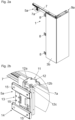
- Fig. 2a shows a portion of the furniture 1, with the furniture part 3a for reasons of improved overview is hidden.
- the guide rail 7 is arranged on an upper side of the furniture body 2 and essentially parallel to a front edge of the furniture body 2, wherein the guide carriage 5a, which is to be connected to the furniture part 3a in an articulated manner, can be moved along a guide web 7a of the guide rail 7.
- the guide web 7a can be designed together with the guide rail 7 either in one piece or alternatively as a separate component from the guide rail 7.
- Fig. 2b shows the in Fig. 2a circled area in an enlarged view, which shows the construction of the guide carriage 5a in more detail.
- the guide carriage 5a includes a chassis 11 with at least one (not visible here) rotatable roller 17a, 17b ( Fig. 3 ), which can be rolled along the guide rail 7.
- the guide carriage 5a also has a connecting part 13 for connecting to the furniture part 3a, the chassis 11 and the connecting part 13 being designed as separate structural units and having at least one fastening device 18 ( Fig. 3 ) can be detachably connected to one another.
- the connecting part 13 comprises a fitting part 14 for fastening the furniture part 3a, the fitting part 14 in an assembled state about a vertically extending axis 27 ( Fig.
- the fitting part 14 can have at least one or more fastening points 15, for example in the form of holes, for fastening to the furniture part 3a.
- the chassis 11 comprises a section 12 with a U-shaped cross section, which in an assembled state surrounds the guide web 7a of the guide rail 7 at least in some areas.
- the U-shaped section 12 has a base web 12a and two legs 12b and 12c projecting downwards from the base web 12a, wherein in an assembled state the at least one rotatably mounted roller 17a, 17b is mounted on a first leg 12b and the connecting part 13 on a second leg 12c of the U-shaped Section 12 can be arranged.
- Fig. 3 shows the guide carriage 5a in a cross section.
- the chassis 11 has at least one roller 17a, 17b, which can be moved along the guide rail 7.
- two or more rollers 17a, 17b are provided, which are spaced apart from one another in a height direction.
- a first roller 17a has a substantially horizontally extending axis of rotation in an assembled state, while a second roller 17b can be rotated about a substantially vertically extending axis of rotation in an assembled state.
- the rollers 17a, 17b are mounted on the first leg 12b of the U-shaped section 12, while the connecting part 13 for fastening the furniture part 3a on the second leg 12c of the U-shaped section 12 is to be mounted.
- the connecting part 13 has a fitting part 14 which can be pivoted about the vertical axis 27 and has the fastening points 15 ( Fig. 2b ) for attachment to the furniture part 3a.
- the connecting part 13 is to be mounted on the chassis 11 via at least one fastening device 18.
- the fastening device 18 comprises at least one movably mounted locking element 19, which is biased towards a locking position by a force accumulator 21 (for example in the form of a coil spring, a torsion spring or a spiral spring).
- the locking element 19 can be releasably locked with a coupling element 22 arranged on a chassis 11.
- the locking element 19 is provided with at least one recess 23, which can be brought into engagement with the coupling element 22 arranged on the chassis 11.
- the locking element 19 is pivotally mounted about an axis 20 which runs horizontally in an assembled state.
- a holding device 24 separate from the fastening device 18 is provided for fastening the connecting part 13 to the chassis 11.
- the holding device 24 and the fastening device 18 are spaced apart from one another in a height direction in an assembled state.
- the holding device 24 has at least one notch 25 arranged on the connecting part 13 for hanging the connecting part 13 on the chassis 11.
- At least one holding element 26 is arranged or formed on the chassis 11, which is in a fastened state of the connecting part 13 engages in the notch 25.
- the connecting part 13 can be hung on the chassis 11 via the holding device 24, then the connecting part 13 suspended on the chassis 11 is pivoted about an axis 16, preferably formed by the holding element 26, and finally connected to the chassis via the at least one locking element 19 11 releasably locked.
- Fig. 4 shows the locked state of the connecting part 13 on the chassis 11 in a cross section.
- the connecting part 13 By hanging the notch 25 of the holding device 24 on the holding element 26, the connecting part 13 can be pivoted about a horizontal axis 16 relative to the chassis 11.
- a positive lock between the connecting part 13 and the chassis 11 can be produced by the fastening device 18 with the locking element 19.
- the locking element 19 interacts with the coupling element 22, the locking element 19 is first moved against a force of the energy accumulator 21, then the locking element 19 can be automatically locked with the coupling element 22 by the force of the relaxing energy accumulator 21.
- the connection between the connecting part 13 and the chassis 11 In a locked state, the connection between the connecting part 13 and the chassis 11 can be released by exerting force on the locking element 19 against the force of the energy accumulator 21.
- the locking element 19 In a locked state between the connecting part 13 and the chassis 11, the locking element 19 is freely accessible to a person and can be actuated directly for manual operation or for operation using a
- the locking element 19 of the fastening device 18 and the notch 25 of the holding device 24 are arranged or formed on the connecting part 13.
- the locking element 19 of the fastening device 18 and the notch 25 of the holding device 24 it is also possible for the locking element 19 of the fastening device 18 and the notch 25 of the holding device 24 to be arranged on the chassis 11, in which case the coupling element 22 and the holding element 26 would have to be arranged on the connecting part 13.
- Fig. 5 shows the guide carriage 5a with the chassis 11 and the connecting part 13 to be attached to it in a perspective view.
- the chassis 11 can have several rollers 17a with a horizontal axis of rotation and several rollers 17b with a vertical axis of rotation.
- the connecting part 13 is pre-positioned on the chassis 11 by the holding device 24, with the holding element 26 of the holding device 24 in the notch 25 ( Fig. 3 ) of the connecting part 13 intervenes.
- the connecting part 13 can be pivoted about a horizontally extending axis 16 formed by the holding element 26, whereupon an automatic locking with the coupling element 22 of the chassis 11 can be brought about by the locking element 19 prestressed by the energy accumulator 21.
- the coupling element 22 of the fastening device 18 and/or the holding element 26 of the holding device 24 can or can be designed as a cylindrical pin or as a cylindrical rod.
- the locking element 19 can be provided with an inclined surface 19a, through which the locking element 19 counteracts the force when interacting with the coupling element 22 of the energy storage 21 is movable in a first direction of rotation, so that the energy storage 21 is charged.
- the locking element 19 When the coupling element 22 enters the recess 23 of the locking element 19, the locking element 19 is moved by the force of the charged energy accumulator 21 in a second direction of rotation opposite to the first direction of rotation, the locking element 19 being able to be locked in a form-fitting manner with the coupling element 22.
- Fig. 6 shows the guide carriage 5a in another perspective view.
- the connecting part 13 is prepositioned at a predetermined height relative to the chassis 11 via the holding device 24 (holding element 26 in notch 25).
- the connecting part 13 can be releasably locked to the chassis 11 by the locking element 19.
- the locking element 19 can have an actuation section 19b, the lock being releasable by manual actuation or by actuation of the actuation section 19b using a tool.
- the guide carriage 5a also has at least one adjusting device 28 with a movably mounted adjusting element 28a, with a position of the connecting part 13 relative to the chassis 11 being adjustable by actuating the adjusting element 28a in a locked state between the connecting part 13 and the chassis 11.
- the fitting part 14 of the connecting part 13 is pivotally mounted about a vertical axis 27 relative to a bearing part 30.
- the adjusting device 28 comprises at least one movably mounted adjusting element 28a, by an actuation of the adjusting element 28a, a position of the fitting part 14 can be adjusted relative to the chassis 11.
- the adjusting device 28 is designed to adjust the height of the fitting part 14.
- the adjusting element 28a is rotatably mounted on a support part 29, but is axially immovable.
- the support part 29 is supported on the coupling element 22, with a threaded section 28b of the adjusting element 28a being in threaded engagement with the bearing part 30.
- a height position of the bearing part 30 and thus a height position of the fitting part 14 can be adjusted, so that in an assembled state, a height position of the furniture part 3a connected to the fitting part 14 can also be adjusted.
- further adjustment devices 28 can also be provided, through which the fitting part 14 can be adjusted in a lateral direction and/or in a depth direction relative to the chassis 11.
Applications Claiming Priority (3)
| Application Number | Priority Date | Filing Date | Title |
|---|---|---|---|
| AT509792018A AT521140B1 (de) | 2018-11-13 | 2018-11-13 | Führungsschlitten zur verfahrbaren Lagerung eines Möbelteiles |
| PCT/AT2019/060370 WO2020097647A1 (fr) | 2018-11-13 | 2019-11-05 | Chariot de guidage servant au montage mobile d'un élément de meuble |
| EP19804614.6A EP3880921B1 (fr) | 2018-11-13 | 2019-11-05 | Chariot de guidage servant au montage mobile d'un élément de meuble |
Related Parent Applications (1)
| Application Number | Title | Priority Date | Filing Date |
|---|---|---|---|
| EP19804614.6A Division EP3880921B1 (fr) | 2018-11-13 | 2019-11-05 | Chariot de guidage servant au montage mobile d'un élément de meuble |
Publications (2)
| Publication Number | Publication Date |
|---|---|
| EP4245954A2 true EP4245954A2 (fr) | 2023-09-20 |
| EP4245954A3 EP4245954A3 (fr) | 2023-10-04 |
Family
ID=68502104
Family Applications (2)
| Application Number | Title | Priority Date | Filing Date |
|---|---|---|---|
| EP19804614.6A Active EP3880921B1 (fr) | 2018-11-13 | 2019-11-05 | Chariot de guidage servant au montage mobile d'un élément de meuble |
| EP23190514.2A Pending EP4245954A3 (fr) | 2018-11-13 | 2019-11-05 | Chariot de guidage pour le montage mobile d'une partie de meuble |
Family Applications Before (1)
| Application Number | Title | Priority Date | Filing Date |
|---|---|---|---|
| EP19804614.6A Active EP3880921B1 (fr) | 2018-11-13 | 2019-11-05 | Chariot de guidage servant au montage mobile d'un élément de meuble |
Country Status (8)
| Country | Link |
|---|---|
| US (1) | US11725441B2 (fr) |
| EP (2) | EP3880921B1 (fr) |
| JP (1) | JP7250926B2 (fr) |
| CN (1) | CN113015838B (fr) |
| AT (1) | AT521140B1 (fr) |
| ES (1) | ES2963084T3 (fr) |
| TW (1) | TWI712729B (fr) |
| WO (1) | WO2020097647A1 (fr) |
Families Citing this family (3)
| Publication number | Priority date | Publication date | Assignee | Title |
|---|---|---|---|---|
| AT521828B1 (de) * | 2018-11-13 | 2022-09-15 | Blum Gmbh Julius | Anordnung zur Führung wenigstens einer Falt-Schiebe-Tür |
| AT523303B1 (de) * | 2019-12-19 | 2023-04-15 | Blum Gmbh Julius | Führungsvorrichtung zur Führung eines Möbelteils |
| AT523374B1 (de) * | 2019-12-19 | 2021-10-15 | Blum Gmbh Julius | Verbindungsvorrichtung, insbesondere Scharnier |
Citations (3)
| Publication number | Priority date | Publication date | Assignee | Title |
|---|---|---|---|---|
| DE3903700A1 (de) | 1989-02-08 | 1990-08-09 | Yoshiji Tutikawa | Lagerung fuer falttueren |
| EP0610557A1 (fr) | 1993-01-23 | 1994-08-17 | Paul Hettich Gmbh & Co. | Ensemble de guidage à rail pour portes coulissantes, portes coulissantes et pliantes, fenêtrès coulissantes ou sémilaires |
| EP2894285A1 (fr) | 2014-01-10 | 2015-07-15 | Argent Alu nv | Élément de couplage, procédé pour suspendre un vantail de porte coulissante à partir d'un corps de rouleau et procédé pour libérer un vantail de porte coulissante à partir d'un corps de rouleau |
Family Cites Families (32)
| Publication number | Priority date | Publication date | Assignee | Title |
|---|---|---|---|---|
| US1195197A (en) * | 1916-08-22 | op sterling | ||
| US1787468A (en) * | 1928-05-07 | 1931-01-06 | Nat Mfg Co | Door hanger |
| US3829929A (en) * | 1971-05-07 | 1974-08-20 | Lawrence Brothers | Folding door hanger with emergency release |
| US3793673A (en) * | 1971-11-17 | 1974-02-26 | Lawrence Brothers | Laterally adjustable door hanger |
| US3757384A (en) * | 1972-02-03 | 1973-09-11 | Lawrence Brothers | Hanger device |
| JPS58159372A (ja) | 1982-03-17 | 1983-09-21 | Toshiba Corp | 半導体装置 |
| JPS58159372U (ja) * | 1982-04-16 | 1983-10-24 | 株式会社ダイケン | スライデイングランナ− |
| GB2162225B (en) * | 1984-07-18 | 1987-09-09 | Genaplast Pty Ltd | Sliding door mechanism |
| US5085262A (en) | 1989-02-08 | 1992-02-04 | Daiyusu Kinzoku Co., Ltd. | Device for supporting folding doors |
| DE29507937U1 (de) * | 1995-05-13 | 1996-11-07 | Inbauproduct Innenausbausystem | Laufrollenbeschlag für Falttürschränke |
| US6209171B1 (en) * | 1999-10-01 | 2001-04-03 | The Stanley Works | Movable door mounting assembly |
| US6983512B2 (en) * | 2002-07-23 | 2006-01-10 | Masco Corporation | Movable door mounting assembly with trolley locking structure |
| JP3878526B2 (ja) * | 2002-08-20 | 2007-02-07 | 株式会社Skb | ランナー |
| WO2004040091A1 (fr) * | 2002-11-01 | 2004-05-13 | Sugatsune Kogyo Co., Ltd. | Dispositif a galets pour porte coulissante |
| JP4469147B2 (ja) * | 2003-07-09 | 2010-05-26 | スワン商事株式会社 | 引違い折畳み開閉自在のサッシ |
| US7117559B1 (en) * | 2004-08-14 | 2006-10-10 | David Barber | Support system for pocket doors |
| KR200385680Y1 (ko) | 2005-03-21 | 2005-06-01 | (주)성광프로젝트 | 미닫이 도어의 착탈구조 |
| TWM343050U (en) | 2008-05-21 | 2008-10-21 | Only Ind Corp | Positioning member capable of preventing shaft rod from releasing |
| PL2781677T3 (pl) * | 2009-07-31 | 2020-01-31 | Allegion (Uk) Limited | Zespół wózka |
| FR2958141B1 (fr) * | 2010-03-31 | 2012-08-03 | Somfy Sas | Chariot d'entrainement pour rideau coulissant |
| IT1402853B1 (it) * | 2010-10-28 | 2013-09-27 | Terno Scorrevoli Srl | Staffa a innesto frontale per carrellini di ante o porte scorrevoli |
| SE535000C2 (sv) * | 2010-07-07 | 2012-03-13 | Assa Abloy Ip Ab | Löpvagn för en skjutdörr och metod för byte av hjul på en löpvagn samt användning |
| US8984716B2 (en) * | 2013-02-25 | 2015-03-24 | Anthony Innovations Pty Ltd. | Roller wheel carriage and bearing assembly |
| AT516282B1 (de) | 2014-11-26 | 2016-04-15 | Blum Gmbh Julius | Anordnung zum Aufspreizen wenigstens zweier gelenkig miteinander verbundener Türflügel |
| CN106320906B (zh) * | 2016-10-21 | 2018-07-27 | 广东顶固集创家居股份有限公司 | 固定装置 |
| AT519374B1 (de) * | 2017-01-13 | 2018-06-15 | Blum Gmbh Julius | Führungssystem zur Führung eines bewegbar gelagerten Möbelteiles |
| US10604930B2 (en) * | 2017-02-15 | 2020-03-31 | Hunter Douglas Inc. | Friction adjustment member for architectural covering |
| JP6761988B2 (ja) * | 2017-03-17 | 2020-09-30 | パナソニックIpマネジメント株式会社 | 引戸装置 |
| US9976329B1 (en) * | 2017-05-05 | 2018-05-22 | Caldwell Manufacturing Company North America, LLC | Adjustable carriage assembly for suspending a panel |
| IT201700081786A1 (it) * | 2017-07-19 | 2019-01-19 | Terno Scorrevoli S P A Unipersonale | Dispositivo di scorrimento per porte e ante di armadi provvisto di regolazioni multiple |
| JP6453496B2 (ja) * | 2018-01-24 | 2019-01-16 | 株式会社ソリック | 吊り金具装置 |
| CN108150041B (zh) * | 2018-02-09 | 2023-08-15 | 广东东泰五金精密制造有限公司 | 一种家具折叠门的自动拆装机构 |
-
2018
- 2018-11-13 AT AT509792018A patent/AT521140B1/de active
-
2019
- 2019-11-05 CN CN201980074732.6A patent/CN113015838B/zh active Active
- 2019-11-05 WO PCT/AT2019/060370 patent/WO2020097647A1/fr unknown
- 2019-11-05 JP JP2021525867A patent/JP7250926B2/ja active Active
- 2019-11-05 EP EP19804614.6A patent/EP3880921B1/fr active Active
- 2019-11-05 ES ES19804614T patent/ES2963084T3/es active Active
- 2019-11-05 EP EP23190514.2A patent/EP4245954A3/fr active Pending
- 2019-11-11 TW TW108140831A patent/TWI712729B/zh active
-
2021
- 2021-05-11 US US17/317,458 patent/US11725441B2/en active Active
Patent Citations (3)
| Publication number | Priority date | Publication date | Assignee | Title |
|---|---|---|---|---|
| DE3903700A1 (de) | 1989-02-08 | 1990-08-09 | Yoshiji Tutikawa | Lagerung fuer falttueren |
| EP0610557A1 (fr) | 1993-01-23 | 1994-08-17 | Paul Hettich Gmbh & Co. | Ensemble de guidage à rail pour portes coulissantes, portes coulissantes et pliantes, fenêtrès coulissantes ou sémilaires |
| EP2894285A1 (fr) | 2014-01-10 | 2015-07-15 | Argent Alu nv | Élément de couplage, procédé pour suspendre un vantail de porte coulissante à partir d'un corps de rouleau et procédé pour libérer un vantail de porte coulissante à partir d'un corps de rouleau |
Also Published As
| Publication number | Publication date |
|---|---|
| CN113015838A (zh) | 2021-06-22 |
| AT521140B1 (de) | 2019-11-15 |
| TW202028591A (zh) | 2020-08-01 |
| EP3880921A1 (fr) | 2021-09-22 |
| US20210262266A1 (en) | 2021-08-26 |
| AT521140A4 (de) | 2019-11-15 |
| CN113015838B (zh) | 2023-05-09 |
| WO2020097647A1 (fr) | 2020-05-22 |
| TWI712729B (zh) | 2020-12-11 |
| ES2963084T3 (es) | 2024-03-25 |
| JP7250926B2 (ja) | 2023-04-03 |
| EP4245954A3 (fr) | 2023-10-04 |
| US11725441B2 (en) | 2023-08-15 |
| JP2022507347A (ja) | 2022-01-18 |
| EP3880921B1 (fr) | 2023-08-23 |
Similar Documents
| Publication | Publication Date | Title |
|---|---|---|
| AT509416B1 (de) | Ausziehführung für eine schublade | |
| WO2018204947A1 (fr) | Système de guidage pour le guidage d'un battant de porte | |
| EP2710209B1 (fr) | Support pour une porte coulissante | |
| EP3880921B1 (fr) | Chariot de guidage servant au montage mobile d'un élément de meuble | |
| EP3625417B1 (fr) | Bras de commande réglable en longueur | |
| DE202009014811U1 (de) | Möbelbeschlag zum lösbaren Verbinden zweier Möbelteile | |
| AT519781A1 (de) | Schubladenwand | |
| EP3818224B1 (fr) | Ferrure pour meuble | |
| EP3760076A1 (fr) | Broche de raccordement pour parties de meuble | |
| EP3580418B1 (fr) | Charnière pour meuble facile à monter | |
| WO2018033221A1 (fr) | Charnière de meuble | |
| EP3058156B1 (fr) | Dispositif de guidage d'une porte coulissante, et procédé de montage d'une porte coulissante | |
| AT515689B1 (de) | Schublade | |
| AT507690B1 (de) | Möbelbeschlag zum lösbaren verbinden zweier möbelteile | |
| AT520427B1 (de) | Befestigungsvorrichtung zum lösbaren Befestigen einer Frontblende an einer Schublade | |
| EP3622144B1 (fr) | Charnière de meuble | |
| EP3622143B1 (fr) | Charnière de meuble | |
| AT518048B1 (de) | Schubladenwand | |
| AT522096B1 (de) | Anordnung mit wenigstens einer Schubladenausziehführung und mit wenigstens einer Verriegelungsvorrichtung zum lösbaren Verriegeln eines ausziehbaren Möbelteiles | |
| AT521333B1 (de) | Schubladenausziehführung |
Legal Events
| Date | Code | Title | Description |
|---|---|---|---|
| PUAI | Public reference made under article 153(3) epc to a published international application that has entered the european phase |
Free format text: ORIGINAL CODE: 0009012 |
|
| STAA | Information on the status of an ep patent application or granted ep patent |
Free format text: STATUS: THE APPLICATION HAS BEEN PUBLISHED |
|
| REG | Reference to a national code |
Ref country code: DE Ref legal event code: R079 Free format text: PREVIOUS MAIN CLASS: E05D0015260000 Ipc: E05D0015060000 |
|
| PUAL | Search report despatched |
Free format text: ORIGINAL CODE: 0009013 |
|
| AC | Divisional application: reference to earlier application |
Ref document number: 3880921 Country of ref document: EP Kind code of ref document: P |
|
| AK | Designated contracting states |
Kind code of ref document: A2 Designated state(s): AL AT BE BG CH CY CZ DE DK EE ES FI FR GB GR HR HU IE IS IT LI LT LU LV MC MK MT NL NO PL PT RO RS SE SI SK SM TR |
|
| AK | Designated contracting states |
Kind code of ref document: A3 Designated state(s): AL AT BE BG CH CY CZ DE DK EE ES FI FR GB GR HR HU IE IS IT LI LT LU LV MC MK MT NL NO PL PT RO RS SE SI SK SM TR |
|
| RIC1 | Information provided on ipc code assigned before grant |
Ipc: E05D 15/26 20060101ALI20230829BHEP Ipc: E05D 15/06 20060101AFI20230829BHEP |
|
| P01 | Opt-out of the competence of the unified patent court (upc) registered |
Effective date: 20231004 |
|
| STAA | Information on the status of an ep patent application or granted ep patent |
Free format text: STATUS: REQUEST FOR EXAMINATION WAS MADE |
|
| 17P | Request for examination filed |
Effective date: 20240319 |
|
| RBV | Designated contracting states (corrected) |
Designated state(s): AL AT BE BG CH CY CZ DE DK EE ES FI FR GB GR HR HU IE IS IT LI LT LU LV MC MK MT NL NO PL PT RO RS SE SI SK SM TR |