EP4241973A1 - Vorrichtung zur formung eines batteriepolstücks und formungsverfahren - Google Patents
Vorrichtung zur formung eines batteriepolstücks und formungsverfahren Download PDFInfo
- Publication number
- EP4241973A1 EP4241973A1 EP21918740.8A EP21918740A EP4241973A1 EP 4241973 A1 EP4241973 A1 EP 4241973A1 EP 21918740 A EP21918740 A EP 21918740A EP 4241973 A1 EP4241973 A1 EP 4241973A1
- Authority
- EP
- European Patent Office
- Prior art keywords
- press roller
- structures
- mounting
- pole piece
- press
- Prior art date
- Legal status (The legal status is an assumption and is not a legal conclusion. Google has not performed a legal analysis and makes no representation as to the accuracy of the status listed.)
- Pending
Links
Images



Classifications
-
- B—PERFORMING OPERATIONS; TRANSPORTING
- B30—PRESSES
- B30B—PRESSES IN GENERAL
- B30B3/00—Presses characterised by the use of rotary pressing members, e.g. rollers, rings, discs
-
- B—PERFORMING OPERATIONS; TRANSPORTING
- B05—SPRAYING OR ATOMISING IN GENERAL; APPLYING FLUENT MATERIALS TO SURFACES, IN GENERAL
- B05C—APPARATUS FOR APPLYING FLUENT MATERIALS TO SURFACES, IN GENERAL
- B05C19/00—Apparatus specially adapted for applying particulate materials to surfaces
- B05C19/008—Accessories or implements for use in connection with applying particulate materials to surfaces; not provided elsewhere in B05C19/00
-
- B—PERFORMING OPERATIONS; TRANSPORTING
- B30—PRESSES
- B30B—PRESSES IN GENERAL
- B30B3/00—Presses characterised by the use of rotary pressing members, e.g. rollers, rings, discs
- B30B3/04—Presses characterised by the use of rotary pressing members, e.g. rollers, rings, discs co-operating with one another, e.g. with co-operating cones
-
- B—PERFORMING OPERATIONS; TRANSPORTING
- B30—PRESSES
- B30B—PRESSES IN GENERAL
- B30B15/00—Details of, or accessories for, presses; Auxiliary measures in connection with pressing
- B30B15/30—Feeding material to presses
-
- H—ELECTRICITY
- H01—ELECTRIC ELEMENTS
- H01M—PROCESSES OR MEANS, e.g. BATTERIES, FOR THE DIRECT CONVERSION OF CHEMICAL ENERGY INTO ELECTRICAL ENERGY
- H01M10/00—Secondary cells; Manufacture thereof
- H01M10/04—Construction or manufacture in general
- H01M10/0404—Machines for assembling batteries
-
- H—ELECTRICITY
- H01—ELECTRIC ELEMENTS
- H01M—PROCESSES OR MEANS, e.g. BATTERIES, FOR THE DIRECT CONVERSION OF CHEMICAL ENERGY INTO ELECTRICAL ENERGY
- H01M10/00—Secondary cells; Manufacture thereof
- H01M10/05—Accumulators with non-aqueous electrolyte
- H01M10/052—Li-accumulators
- H01M10/0525—Rocking-chair batteries, i.e. batteries with lithium insertion or intercalation in both electrodes; Lithium-ion batteries
-
- H—ELECTRICITY
- H01—ELECTRIC ELEMENTS
- H01M—PROCESSES OR MEANS, e.g. BATTERIES, FOR THE DIRECT CONVERSION OF CHEMICAL ENERGY INTO ELECTRICAL ENERGY
- H01M4/00—Electrodes
- H01M4/02—Electrodes composed of, or comprising, active material
- H01M4/04—Processes of manufacture in general
- H01M4/0402—Methods of deposition of the material
- H01M4/0409—Methods of deposition of the material by a doctor blade method, slip-casting or roller coating
-
- H—ELECTRICITY
- H01—ELECTRIC ELEMENTS
- H01M—PROCESSES OR MEANS, e.g. BATTERIES, FOR THE DIRECT CONVERSION OF CHEMICAL ENERGY INTO ELECTRICAL ENERGY
- H01M4/00—Electrodes
- H01M4/02—Electrodes composed of, or comprising, active material
- H01M4/13—Electrodes for accumulators with non-aqueous electrolyte, e.g. for lithium-accumulators; Processes of manufacture thereof
- H01M4/139—Processes of manufacture
-
- B—PERFORMING OPERATIONS; TRANSPORTING
- B30—PRESSES
- B30B—PRESSES IN GENERAL
- B30B9/00—Presses specially adapted for particular purposes
- B30B9/28—Presses specially adapted for particular purposes for forming shaped articles
-
- Y—GENERAL TAGGING OF NEW TECHNOLOGICAL DEVELOPMENTS; GENERAL TAGGING OF CROSS-SECTIONAL TECHNOLOGIES SPANNING OVER SEVERAL SECTIONS OF THE IPC; TECHNICAL SUBJECTS COVERED BY FORMER USPC CROSS-REFERENCE ART COLLECTIONS [XRACs] AND DIGESTS
- Y02—TECHNOLOGIES OR APPLICATIONS FOR MITIGATION OR ADAPTATION AGAINST CLIMATE CHANGE
- Y02E—REDUCTION OF GREENHOUSE GAS [GHG] EMISSIONS, RELATED TO ENERGY GENERATION, TRANSMISSION OR DISTRIBUTION
- Y02E60/00—Enabling technologies; Technologies with a potential or indirect contribution to GHG emissions mitigation
- Y02E60/10—Energy storage using batteries
Definitions
- the present application relates to the field of battery pole piece production equipment, for example, a battery pole piece forming apparatus and method.
- a lithium-ion battery With a large energy density, a lithium-ion battery has been applied to a device such as a mobile phone or a laptop. However, as lithium-ion batteries have broader and more advanced use, a lithium-ion battery is required to have a better performance including a low resistance and a large capacity.
- the electrode of a lithium-ion battery may be a battery pole piece.
- a powder calendering device is used to compression mold the powder.
- a powder calendering device two press rollers each compression mold powder on a respective side of a substrate to obtain a battery pole piece.
- the substrate is prone to jitter when being conveyed, causing powders on two sides of the substrate to have different thicknesses.
- the battery pole piece swells differently in different areas of the battery pole piece. As a result, the powders easily fall from the substrate, affecting the subsequent normal operation of the lithium-ion battery.
- the present application provides a battery pole piece forming apparatus and method, solving a problem of the related art in which powders on two sides of a substrate have different thicknesses and thus affect the subsequent normal operation of a lithium-ion battery.
- a battery pole piece forming apparatus includes a conveying mechanism configured to convey a substrate; a feeding mechanism; and a press roller mechanism.
- the press roller mechanism includes a first press roller, a second press roller, a third press roller, and a fourth press roller arranged side by side in sequence.
- the spacing between the first press roller and the second press roller is the same as the spacing between the third press roller and the fourth press roller.
- the second press roller and the third press roller are configured to make the substrate pass between the second press roller and the third press roller along the vertical direction.
- the first press roller and the second press roller are configured to roll-press active substance particles conveyed by the feeding mechanism to form a first membrane.
- the third press roller and the fourth press roller are configured to roll-press active substance particles conveyed by the feeding mechanism to form a second membrane.
- the second press roller and the third press roller are configured to roll-press the first membrane and the second membrane onto one side of the substrate and another side of the substrate respectively.
- An embodiment provides a battery pole piece forming method.
- the method is applied to the battery pole piece forming apparatus and includes roll-pressing active substance particles to form a first membrane and a second membrane that have the same thickness; and roll-pressing the first membrane and the second membrane onto one side of a substrate and another side of the substrate respectively.
- connection may refer to “fixedly connected”, “detachably connected”, or integrated, may refer to “mechanically connected” or “electrically connected”, or may refer to “connected directly”, “connected indirectly through an intermediary”, “connected inside two components”, or “interaction relations between two components".
- connection relations between two components.
- first feature and the second feature may be in direct contact or be in contact via another feature between the two features instead of being in direct contact.
- first feature is described as “on”, “above”, or “over” the second feature
- first feature is right on, above, or over the second feature or the first feature is obliquely on, above, or over the second feature, or the first feature is simply at a higher level than the second feature.
- the first feature When the first feature is described as “under”, “below”, or “underneath” the second feature, the first feature is right under, below, or underneath the second feature or the first feature is obliquely under, below, or underneath the second feature, or the first feature is simply at a lower level than the second feature.
- orientations or position relations indicated by terms such as “above”, “below”, “right” and the like are based on orientations or position relations shown in the drawings. These orientations or position relations are intended only to facilitate and simplify description of the present application, and not to indicate or imply that a device or element referred to must have such specific orientations or must be configured or operated in such specific orientations. Thus, these orientations or position relations are not to be construed as limiting the present application.
- first and “second” are used only to distinguish between descriptions and have no special meaning.
- the battery pole piece forming apparatus includes a conveying mechanism 2 configured to convey a substrate 100; a feeding mechanism 3; and a press roller mechanism 4.
- the press roller mechanism 4 includes a first press roller 41, a second press roller 42, a third press roller 43, and a fourth press roller 44 arranged side by side in sequence.
- the spacing between the first press roller 41 and the second press roller 42 is the same as the spacing between the third press roller 43 and the fourth press roller 44.
- the second press roller 42 and the third press roller 43 are configured to make the substrate 100 pass between the second press roller 42 and the third press roller 43 along the vertical direction.
- the first press roller 41 and the second press roller 42 are configured to roll-press active substance particles conveyed by the feeding mechanism 3 to form a first membrane.
- the third press roller 43 and the fourth press roller 44 are configured to roll-press active substance particles conveyed by the feeding mechanism 3 to form a second membrane.
- the second press roller 42 and the third press roller 43 are configured to roll-press the first membrane and the second membrane onto one side of the substrate 100 and another side of the substrate 100 respectively.
- the rotation direction of the first press roller 41 is opposite to the rotation direction of the third press roller 43.
- the rotation direction of the second press roller 42 is opposite to the rotation direction of the fourth press roller 44.
- the first membrane roll-pressed by the first press roller 41 and the second press roller 42 is attached to the second press roller 42.
- the second membrane roll-pressed by the third press roller 43 and the fourth press roller 44 is attached to the third press roller 43.
- the second press roller 42 and the third press roller 43 roll-press the first membrane and the second membrane onto one side of the substrate 100 and another side of the substrate 100 respectively.
- the first membrane and the second membrane on two sides of the substrate 100 have the same thickness so that the formed battery pole piece has a uniform thickness.
- the temperature of the first press roller 41 is greater than the temperature of the second press roller 42.
- the temperature of the first press roller 41 is 40°C to 300°C
- the temperature of the second press roller 42 is room temperature, so that the first membrane can be better attached to the second press roller 42 after being roll-formed.
- the temperature of the fourth press roller 44 is greater than the temperature of the third press roller 43.
- the temperature of the fourth press roller 44 is 40°C to 300°C
- the temperature of the third press roller 43 is room temperature, so that the second membrane can be better attached to the third press roller 43 after being roll-formed.
- the first press roller 41, the second press roller 42, the third press roller 43, and the fourth press roller 44 are each 0.4 ⁇ m to 0.8 ⁇ m in roughness.
- the feeding mechanism 3 includes at least two hoppers 31.
- a feeding port of at least one of the at least two hoppers 31 is located between and disposed above the first press roller 41 and the second press roller 42.
- a feeding port of at least one of the at least two hoppers 31 is located between and disposed above the third press roller 43 and the fourth press roller 44.
- the feeding mechanism 3 includes two hoppers 31. It is to be understood that the first membrane is roll-formed from active substance particles conveyed by its corresponding hopper 31, and the second membrane is roll-formed from active substance particles conveyed by its corresponding hopper 31. In this manner, when the two hoppers convey active substance particles at the same rate, the active substance particles are conveyed uniformly, and thereby the first membrane and the second membrane can have the same thickness.
- more than two hoppers 31 may be provided.
- the conveying mechanism 2 includes a first support member 21 and a second support member 22.
- the first support member 21 is configured to support a substrate web.
- a winding roller is disposed on the second support member 22 and configured to drive the substrate 100 to pass between the second press roller 42 and the third press roller 43.
- the conveying mechanism 2 also includes two first support rollers 23 configured to support the substrate 100. One of the two first support rollers 23 is arranged above the other of the two first support rollers 23 so that the substrate 100 located between the two first support rollers 23 is vertically arranged.
- the substrate 100 between the two first support rollers 23 vertically passes between the second press roller 42 and the third press roller 43 under the action of the two first support rollers 23 so that the second press roller 42 roll-presses the first membrane onto one side of the substrate 100 and the third press roller 43 roll-presses the second membrane onto another side of the substrate 100.
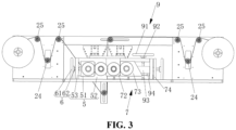
- the conveying mechanism 2 also includes a second support roller 24 and a third support roller 25. At least one second support roller 24 and at least one third support roller 25 are located between the first support member 21 and the press roller mechanism 4. At least one second support roller 24 and at least one third support roller 25 are located between the second support member 22 and the press roller mechanism 4. The second support roller 24 and the third support roller 25 can support and tension the substrate 100. In this embodiment, one second support roller 24 and two third support rollers 25 are disposed between the first support member 21 and the press roller mechanism 4. In an embodiment, as shown in FIG. 3 , the second support roller 24 is located between the two third support rollers 25 and is vertically located below the two third support rollers 25.
- One second support roller 24 and two third support rollers 25 are disposed between the second support member 22 and the press roller mechanism 4.
- the second support roller 24 is located between the two third support rollers 25 and is vertically located below the two third support rollers 25.
- the substrate 100 passes by from below the two second support rollers 24.
- each second support roller 24 can be vertically adjusted such that the substrate 100 can be tensioned.
- the position of a third support roller 25 may be vertically adjusted such that the substrate 100 can be tensioned.
- the pole piece forming apparatus of this embodiment also includes a support bracket 1.
- the support bracket 1 includes a horizontal support plate 11 and a vertical support plate 12.
- the vertical support plate 12 is connected to and perpendicular to the horizontal support plate 11.
- the first support member 21, the second support member 22, the first support roller 23, the second support roller 24, and the third support roller 25 are each disposed on the vertical support plate 12.
- the vertical support plate 12 is provided with multiple linear guide rails extending along the vertical direction.
- the multiple vertical guide rails correspond to the positions of the two second support rollers 24.
- the two second support rollers 24 are slidably disposed on the linear guide rails so as to be movable in the vertical direction.
- the position of the upper first support roller 23 of the two first support rollers 23 is horizontally adjustable to adjust a verticality of the substrate 100 between the two first support rollers 23; and the position of the lower first support roller 23 of the two first support rollers 23 is vertically adjustable to avoid interference occurred between the substrate 100 and the first press roller 41.
- a third chute 121 is horizontally disposed on the vertical support plate 12, and the upper first support roller 23 of the two first support rollers 23 is slidably disposed in the third chute 121.
- the horizontal support plate 11 is provided with an extension plate 111 extending along the vertical direction.
- a fourth chute 1111 extending along the vertical direction is disposed on the extension plate 111.
- the lower first support roller 23 of the two first support rollers 23 is slidably disposed in the fourth chute 1111.
- the horizontal direction is direction ab of FIG. 2
- the vertical direction is direction cd of FIG. 2 .
- the battery pole piece forming apparatus also includes a first driving mechanism and a first mounting assembly 5.
- the first press roller 41 and the second press roller 42 are mounted on the first mounting assembly 5.
- the first driving mechanism is configured to drive the first press roller 41 to move towards or away from the second press roller 42.
- the first mounting assembly 5 includes two first mounting structures 51 opposite to each other and two second mounting structures 52 opposite to each other, the first press roller 41 is rotatably mounted between the two first mounting structures 51, and the second press roller 42 is rotatably mounted between the two second mounting structures 52.
- each second mounting structure 52 is provided with a first chute, each first mounting structure 51 is slidably disposed in the corresponding first chute, and the first driving mechanism is configured to push the first mounting structure 51 to slide along the corresponding first chute so as to drive the first press roller 41 to move towards or away from the second press roller 42.
- the first mounting assembly 5 also includes two first fasteners 53.
- the two first fasteners 53 are connected to the two second mounting structures 52 one to one.
- the first driving mechanism includes two first driving structures 6.
- the two first driving structures 6 are each configured to drive a respective one of the two first mounting structures 51 to slide.
- each first driving structure 6 includes a first runner 61 and a first connecting rod 62 connected to each other.
- the first connecting rod 62 passes through the corresponding first fastener 53 and is connected to the corresponding first mounting structure 51.
- the first connecting rod 62 is screwed to the corresponding first fastener 53.
- the first runner 61 is configured to rotate to drive the corresponding first mounting structure 51 to slide along the corresponding first chute so that the spacing between the first press roller 41 and the second press roller 42 can be adjusted.
- each first mounting structure 51 includes one first mounting block, and the first press roller 41 is mounted between two first mounting blocks. In other embodiments, each first mounting structure 51 may include multiple first mounting blocks. In this embodiment, each second mounting structure 52 includes one second mounting block, and the second press roller 42 is mounted between two second mounting blocks. In other embodiments, each second mounting structure 52 may include multiple second mounting blocks.
- the first driving mechanism may drive the second press roller 42 to move towards or away from the first press roller 41.
- the first mounting assembly 5 includes two fifth mounting structures opposite to each other and two sixth mounting structures opposite to each other.
- the first press roller 41 is mounted between the two fifth mounting structures.
- the second press roller 42 is mounted between the two sixth mounting structures.
- the first driving mechanism includes two fourth driving mechanisms.
- One of the two fourth driving structures can drive one of the two sixth mounting structures to move towards or away from one corresponding fifth mounting structure.
- Another of the two fourth driving structures can drive another of the two sixth mounting structures to move towards or away from another corresponding fifth mounting structure.
- each fourth driving mechanism may be a cylinder, a motor lead screw, or any other structure that can drive a sixth mounting structure.
- the first driving structures can drive the first press roller 41 and the second press roller 42 to move simultaneously to make the first press roller 41 and the second press roller 42 move towards or away from each other.
- the first driving structures may be designed in any manner as long as they can drive the first press roller 41 and the second press roller 42 to move simultaneously.
- the battery pole piece forming apparatus also includes a second driving mechanism and a second mounting assembly 7 slidably disposed on the horizontal support plate 11.
- the third press roller 43 and the fourth press roller 44 are mounted on the second mounting assembly 7.
- the second driving mechanism is configured to drive the second mounting assembly 7 to move towards or away from the second press roller 42.
- the second mounting assembly 7 includes two support structures 71 opposite to each other.
- the third press roller 43 and the fourth press roller 44 are mounted between the two support structures 71.
- the second mounting assembly 7 also includes two second fasteners 74.
- the two second fasteners 74 correspond to the two support structures 71 one to one.
- the two second fasteners 74 are secured to the horizontal support plate 11.
- the two support structures 71 are slidably disposed on the horizontal support plate 11.
- limiting slots are disposed in the horizontal support plate 11 to correspond to the positions of the support structures 71 in a one-to-one manner.
- the support structures 71 are slidably disposed in the limiting slots in a one-to-one manner.
- a roller is disposed on the support structure 71. The roller makes the support structure 71 roll relative to the horizontal support plate 11 instead of sliding relative to the horizontal support plate 11, reducing the friction between a support structure 71 and the horizontal support plate 11.
- the second driving mechanism includes two second driving structures 8.
- the second driving structures 8 are each configured to drive a respective one of the two support structures 71 to move.
- each second driving structure 8 includes a second runner 81 and a second connecting rod 82 connected to each other.
- the second connecting rod 82 passes through the corresponding second fastener 74 and is connected to the corresponding support structure 71.
- the second connecting rod 82 is screwed to the corresponding second fastener 74.
- the second runner 81 is configured to drive the corresponding support structure 71 to move so that the two second driving structures 8 are each configured to drive a respective one of the two support structures 71 to move, thereby driving the second mounting assembly 7 to move. In this manner, the spacing between the second press roller 42 and the third press roller 43 can be adjusted.
- the second mounting assembly 7 also includes two third mounting structures 72 opposite to each other and two fourth mounting structures 73 opposite to each other.
- the third press roller 43 is mounted between the two third mounting structures 72.
- the fourth press roller 44 is mounted between the two fourth mounting structures 73.
- Each support structure 71 is provided with one third mounting structure 72 and one fourth mounting structure 73.
- the third mounting structure 72 is secured to the corresponding support structure 71.
- the fourth mounting structure 73 is slidably disposed on the corresponding support structure 71.
- the support structure 71 is provided with a second chute.
- the fourth mounting structure 73 is slidably disposed in the second chute.
- the battery pole piece forming apparatus also includes a third driving mechanism.
- the third driving mechanism includes two third driving structures 9.
- Each third driving structure 9 is configured to drive a corresponding fourth mounting structure 73 to move towards or away from a corresponding third mounting structure 72.
- each third driving structure 9 includes a driving member, a pushing block 93, and a first elastic member.
- the driving member is configured to drive the pushing block 93 to move along the vertical direction.
- the driving member includes a third runner 91 and a third connecting rod 92.
- the third runner 91 is connected to the third connecting rod 92.
- the third connecting rod 92 is vertically disposed.
- the first end of the third connecting rod 92 passes through the corresponding support structure 71 and is connected to the pushing block 93.
- the third connecting rod 92 is screwed to the corresponding support structure 71.
- the second end of the third connecting rod 92 is provided with the third runner 91.
- the pushing block 93 is located in the second chute.
- the first elastic member is disposed between the corresponding third mounting structure 72 and the corresponding fourth mounting structure 73.
- the pushing block 93 is provided with a first inclined plane
- the corresponding fourth mounting structure 73 is provided with a second inclined plane abutting against the first inclined plane.
- the pushing block 93 slides downwards along the second inclined plane and make the third connecting rod 92 push the corresponding fourth mounting structure 73 towards the corresponding third mounting structure 72 so that the spacing between the third press roller 43 and the fourth press roller 44 is reduced.
- the first elastic member is compressed.
- the pushing block 93 slides upwards along the second inclined plane, and the corresponding fourth mounting structure 73 is pushed away from the corresponding third mounting structure 72 under the elastic force of the elastic recovery of the first elastic member. In this manner, the spacing between the third press roller 43 and the fourth press roller 44 is increased.
- each third mounting structure 72 includes one third mounting block.
- the third press roller 43 is mounted between two third mounting blocks.
- each third mounting structure 72 may include multiple third mounting blocks.
- each fourth mounting structure 73 includes one fourth mounting block.
- the fourth press roller 44 is mounted between two fourth mounting blocks.
- each fourth mounting structure 73 may include multiple fourth mounting blocks.
- the third press roller 43 may be mounted between the two fourth mounting structures 73, and the fourth press roller 44 may be mounted between the two third mounting structures 72.
- the third driving mechanism includes two third driving structures 9, and each third driving structure 9 can drive the third press roller 43 to move towards or away from the fourth press roller 44.
- a third mounting structure 72 is slidably disposed on the corresponding support structure 71, and a fourth mounting structure 73 is secured to the corresponding support structure 71; and the third driving mechanism includes two third driving structures 9, and each third driving structure 9 can drive the corresponding third mounting structure 72 to move towards or away from the corresponding fourth mounting structure 73.
- a third mounting structure 72 and a fourth mounting structure 73 can be slidably disposed on the corresponding support structure 71.
- the third driving mechanism includes four third driving structures 9, each third mounting structure 72 corresponds to one third driving structure 9, and each fourth mounting structure 73 corresponds to one third driving structure 9.
- each third driving structure 9 also includes a second elastic member 94.
- the second elastic member 94 is disposed between the pushing block 93 and the corresponding support structure 71.
- the second elastic member 94 can buffer the movement of the pushing block 93 and can support the pushing block 93 so that when the third runner 91 stops rotating, the position of the pushing block 93 is kept stable so that the spacing between the third press roller 43 and the fourth press roller 44 is kept stable.
- each support structure 71 includes a first portion 711, a second portion 712, and a third portion 713.
- the second portion 712 is vertically connected to the first portion 711.
- the third portion 713 is vertically connected to the second portion 712.
- the second chute is formed between the first portion 711, the second portion 712, and the third portion 713.
- the first portion 711 is located in the limiting slot.
- a roller is disposed on the first portion 711.
- the second connecting rod 82 is screwed to the second portion 712.
- One surface of the pushing block 93 abuts against the second portion 712.
- the third connecting rod 92 passes through the third portion 713 and is connected to the pushing block 93.
- the third connecting rod 92 is screwed to the third portion 713.
- one end of the first press roller 41 is connected to a first gear 45
- one end of the second press roller 42 is connected to a second gear 46
- one end of the third press roller 43 is connected to a third gear 47
- one end of the fourth press roller 44 is connected to a fourth gear 48.
- the first gear 45 engages with the second gear 46.
- the second gear 46 engages with the third gear 47.
- the third gear 47 engages with the fourth gear 48.
- the battery pole piece forming apparatus of this embodiment includes a first press roller 41, a second press roller 42, a third press roller 43, and a fourth press roller 44.
- the first press roller 41 and the second press roller 42 are configured to roll-press active substance particles to form a first membrane.
- the third press roller 43 and the fourth press roller 44 are configured to roll-press active substance particles to form a second membrane.
- the second press roller 42 and the third press roller 43 are configured to roll-press the first membrane and the second membrane onto one side of the substrate 100 and another side of the substrate 100 respectively.
- the first membrane and the second membrane on two sides of the substrate 100 have the uniform thickness so that the formed battery pole piece has a uniform thickness. In this manner, active substance cannot fall in a subsequent operation process of the lithium-ion battery, thus preventing a short circuit and improving the safety performance of the lithium-ion battery.
- An embodiment provides a battery pole piece forming method. As shown in FIG. 4 , the method includes S10 and S20.
- active substance particles are roll-pressed to form a first membrane and a second membrane that have the same thickness.
- the first membrane and the second membrane are roll-pressed onto one side of the substrate 100 and another side of the substrate 100 respectively.
- roll-pressing of the active substance and forming of the battery pole piece are performed in different steps.
- active substance particles are roll-pressed by a first press roller 41 and a second press roller 42 to form a first membrane
- active substance particles are roll-pressed by a third press roller 43 and a fourth press roller 44 to form a second membrane.
- the first membrane and the second membrane have the same thickness.
- the second press roller 42 and the third press roller 43 roll-press the first membrane and the second membrane onto one side of a substrate 100 and another side of the substrate 100 respectively.
- the first membrane and the second membrane have a more uniform thickness so that the battery pole piece formed after the first membrane and the second membrane are roll-pressed onto the substrate 100 has a uniform thickness. In this manner, active substance cannot fall in a subsequent operation process of the lithium-ion battery, thus preventing a short circuit and improving the safety performance of the lithium-ion battery.
Landscapes
- Engineering & Computer Science (AREA)
- Chemical & Material Sciences (AREA)
- Manufacturing & Machinery (AREA)
- Chemical Kinetics & Catalysis (AREA)
- Electrochemistry (AREA)
- General Chemical & Material Sciences (AREA)
- Materials Engineering (AREA)
- Mechanical Engineering (AREA)
- Battery Electrode And Active Subsutance (AREA)
Applications Claiming Priority (2)
| Application Number | Priority Date | Filing Date | Title |
|---|---|---|---|
| CN202110042215.XA CN112873944B (zh) | 2021-01-13 | 2021-01-13 | 一种电池极片成型设备及成型方法 |
| PCT/CN2021/074986 WO2022151541A1 (zh) | 2021-01-13 | 2021-02-03 | 电池极片成型设备及成型方法 |
Publications (2)
| Publication Number | Publication Date |
|---|---|
| EP4241973A1 true EP4241973A1 (de) | 2023-09-13 |
| EP4241973A4 EP4241973A4 (de) | 2024-09-11 |
Family
ID=76045358
Family Applications (1)
| Application Number | Title | Priority Date | Filing Date |
|---|---|---|---|
| EP21918740.8A Pending EP4241973A4 (de) | 2021-01-13 | 2021-02-03 | Vorrichtung zur formung eines batteriepolstücks und formungsverfahren |
Country Status (4)
| Country | Link |
|---|---|
| US (1) | US20240066549A1 (de) |
| EP (1) | EP4241973A4 (de) |
| CN (1) | CN112873944B (de) |
| WO (1) | WO2022151541A1 (de) |
Cited By (1)
| Publication number | Priority date | Publication date | Assignee | Title |
|---|---|---|---|---|
| CN117564169A (zh) * | 2023-10-26 | 2024-02-20 | 合肥国轩电池科技有限公司 | 一种电池极片压花装置及方法 |
Families Citing this family (7)
| Publication number | Priority date | Publication date | Assignee | Title |
|---|---|---|---|---|
| CN118056285B (zh) * | 2022-07-20 | 2025-09-09 | 宁德时代新能源科技股份有限公司 | 极片制造装置 |
| CN218399544U (zh) * | 2022-11-08 | 2023-01-31 | 宁德时代新能源科技股份有限公司 | 一种辊压装置及测量设备 |
| CN117283310B (zh) * | 2023-11-01 | 2024-04-19 | 江苏智泰新能源科技有限公司 | 钠离子电池极片切片装置及其加工方法 |
| CN117841421A (zh) * | 2024-01-15 | 2024-04-09 | 惠州亿纬锂能股份有限公司 | 膜片制备设备及制备方法 |
| CN118117039B (zh) * | 2024-03-08 | 2024-11-22 | 肇庆理士电源技术有限公司 | 一种锂离子电池干法电极制备装置 |
| CN118768386B (zh) * | 2024-08-29 | 2025-04-08 | 浙江天能电池江苏新能源有限公司 | 一种蓄电池极板辊轧机 |
| CN120461926B (zh) * | 2025-07-03 | 2025-09-09 | 邢台朝阳机械制造有限公司 | 一种锂电池极片辊压设备及辊压方法 |
Family Cites Families (20)
| Publication number | Priority date | Publication date | Assignee | Title |
|---|---|---|---|---|
| CN2395875Y (zh) * | 1999-11-13 | 2000-09-13 | 平阳县天风塑料机械厂 | 双胶辊翻面涂塑复合装置 |
| JP3873719B2 (ja) * | 2000-11-10 | 2007-01-24 | 石川島播磨重工業株式会社 | 粉末圧延装置および粉末圧延方法 |
| JP5662778B2 (ja) * | 2010-12-06 | 2015-02-04 | パナソニックIpマネジメント株式会社 | 塗工装置 |
| KR20130074644A (ko) * | 2011-12-26 | 2013-07-04 | 주식회사 포스코 | 박판 주조 설비 |
| JP6231292B2 (ja) * | 2013-03-29 | 2017-11-15 | トヨタ自動車株式会社 | 粉体塗工装置、およびそれを用いた電極の製造方法 |
| CN103357557A (zh) * | 2013-06-25 | 2013-10-23 | 中国兵器工业第二一三研究所 | 制备锂锰一次电池正极极片的高粘度浆料连续涂布方法 |
| JP6277491B2 (ja) * | 2014-02-25 | 2018-02-14 | パナソニックIpマネジメント株式会社 | 塗膜物の製造装置 |
| JP2016025060A (ja) * | 2014-07-24 | 2016-02-08 | トヨタ自動車株式会社 | リチウムイオン二次電池用電極シートの製造方法 |
| JP6436306B2 (ja) * | 2014-08-25 | 2018-12-12 | パナソニックIpマネジメント株式会社 | 塗膜物の製造装置、及びこれを用いた塗膜物の製造方法 |
| JP6700204B2 (ja) * | 2017-02-02 | 2020-05-27 | トヨタ自動車株式会社 | 電極の製造方法 |
| CN206878098U (zh) * | 2017-07-12 | 2018-01-12 | 宁德时代新能源科技股份有限公司 | 极片补锂装置 |
| CN107571517A (zh) * | 2017-08-07 | 2018-01-12 | 安徽嘉明新材料科技有限公司 | 一种生产新型环保tpu广告布的工艺 |
| CN107574679A (zh) * | 2017-08-07 | 2018-01-12 | 安徽嘉明新材料科技有限公司 | 一种生产新型环保tpu篷布的工艺 |
| CN107584846A (zh) * | 2017-08-07 | 2018-01-16 | 安徽嘉明新材料科技有限公司 | 一种双面贴合生产新型环保tpu篷布的工艺 |
| CN108598372A (zh) * | 2018-06-26 | 2018-09-28 | 东莞塔菲尔新能源科技有限公司 | 一种极片补锂系统及补锂方法 |
| CN108899468B (zh) * | 2018-06-27 | 2021-05-14 | 合肥国轩高科动力能源有限公司 | 一种负极极片补锂的方法 |
| CN109390562B (zh) * | 2018-09-28 | 2021-04-20 | 超威电源集团有限公司 | 一种两侧涂膏的蓄电池电极制造方法 |
| CN111822663B (zh) * | 2019-04-17 | 2021-11-19 | 青岛九环新越新能源科技股份有限公司 | 复合金属带连续生产方法 |
| CN112864346A (zh) * | 2021-01-12 | 2021-05-28 | 惠州亿纬锂能股份有限公司 | 一种极片及其制备方法和电池 |
| CN215152086U (zh) * | 2021-01-13 | 2021-12-14 | 惠州亿纬锂能股份有限公司 | 一种电池极片成型设备 |
-
2021
- 2021-01-13 CN CN202110042215.XA patent/CN112873944B/zh active Active
- 2021-02-03 EP EP21918740.8A patent/EP4241973A4/de active Pending
- 2021-02-03 US US18/272,321 patent/US20240066549A1/en active Pending
- 2021-02-03 WO PCT/CN2021/074986 patent/WO2022151541A1/zh not_active Ceased
Cited By (1)
| Publication number | Priority date | Publication date | Assignee | Title |
|---|---|---|---|---|
| CN117564169A (zh) * | 2023-10-26 | 2024-02-20 | 合肥国轩电池科技有限公司 | 一种电池极片压花装置及方法 |
Also Published As
| Publication number | Publication date |
|---|---|
| EP4241973A4 (de) | 2024-09-11 |
| US20240066549A1 (en) | 2024-02-29 |
| WO2022151541A1 (zh) | 2022-07-21 |
| CN112873944A (zh) | 2021-06-01 |
| CN112873944B (zh) | 2024-12-13 |
Similar Documents
| Publication | Publication Date | Title |
|---|---|---|
| EP4241973A1 (de) | Vorrichtung zur formung eines batteriepolstücks und formungsverfahren | |
| CN112873945B (zh) | 一种电池极片成型设备及成型方法 | |
| CN115064759A (zh) | 一种电芯制成装置及其制成工艺 | |
| CN113479690B (zh) | 一种用于柔性板激光切割的送料系统 | |
| CN213677357U (zh) | 适用于曲面屏贴膜的双滚压装置 | |
| CN111786031A (zh) | 对侧推挡摆动折叠设备 | |
| CN213138183U (zh) | 一种覆膜机的覆膜压合机构 | |
| CN120521516B (zh) | 一种防窥膜生产用厚度激光检测装置 | |
| CN215152086U (zh) | 一种电池极片成型设备 | |
| CN218433470U (zh) | 一种触摸屏生产用传送装置 | |
| CN116834111A (zh) | 一种模切机自动定位调节机构 | |
| CN111562799A (zh) | 一种电子信息识别移动伺服机构 | |
| CN114472674A (zh) | 一种极片成型设备 | |
| CN222388529U (zh) | 飞达设备 | |
| CN210349991U (zh) | 叠片压紧机构及装置 | |
| CN217971884U (zh) | 一种张力调节装置 | |
| CN115113066B (zh) | 一种电池定压测试装置 | |
| CN118493044A (zh) | 一种结构精巧的金属带裁切设备 | |
| CN212277285U (zh) | 对侧推挡摆动折叠设备 | |
| CN222552423U (zh) | 一种极片极耳滚焊装置 | |
| CN222552431U (zh) | 超声波滚焊模组 | |
| CN223173407U (zh) | 一种集流体薄膜辊压设备 | |
| CN220426600U (zh) | 一种金属加工送料装置 | |
| CN222312262U (zh) | 一种pvc压延膜的压延机出料处理装置 | |
| CN113714347B (zh) | 一种自动化钢板弧形弯曲设备 |
Legal Events
| Date | Code | Title | Description |
|---|---|---|---|
| STAA | Information on the status of an ep patent application or granted ep patent |
Free format text: STATUS: THE INTERNATIONAL PUBLICATION HAS BEEN MADE |
|
| PUAI | Public reference made under article 153(3) epc to a published international application that has entered the european phase |
Free format text: ORIGINAL CODE: 0009012 |
|
| STAA | Information on the status of an ep patent application or granted ep patent |
Free format text: STATUS: REQUEST FOR EXAMINATION WAS MADE |
|
| 17P | Request for examination filed |
Effective date: 20230606 |
|
| AK | Designated contracting states |
Kind code of ref document: A1 Designated state(s): AL AT BE BG CH CY CZ DE DK EE ES FI FR GB GR HR HU IE IS IT LI LT LU LV MC MK MT NL NO PL PT RO RS SE SI SK SM TR |
|
| DAV | Request for validation of the european patent (deleted) | ||
| DAX | Request for extension of the european patent (deleted) | ||
| A4 | Supplementary search report drawn up and despatched |
Effective date: 20240812 |
|
| RIC1 | Information provided on ipc code assigned before grant |
Ipc: H01M 10/0525 20100101ALI20240806BHEP Ipc: H01M 4/139 20100101ALI20240806BHEP Ipc: H01M 4/04 20060101ALI20240806BHEP Ipc: B30B 15/30 20060101ALI20240806BHEP Ipc: B30B 9/28 20060101ALI20240806BHEP Ipc: B30B 3/00 20060101AFI20240806BHEP |
|
| STAA | Information on the status of an ep patent application or granted ep patent |
Free format text: STATUS: EXAMINATION IS IN PROGRESS |
|
| 17Q | First examination report despatched |
Effective date: 20250923 |