EP4240997B1 - Valves with integrated orifice restrictions - Google Patents
Valves with integrated orifice restrictions Download PDFInfo
- Publication number
- EP4240997B1 EP4240997B1 EP21816233.7A EP21816233A EP4240997B1 EP 4240997 B1 EP4240997 B1 EP 4240997B1 EP 21816233 A EP21816233 A EP 21816233A EP 4240997 B1 EP4240997 B1 EP 4240997B1
- Authority
- EP
- European Patent Office
- Prior art keywords
- valve
- orifice
- seat
- wall
- annular inner
- Prior art date
- Legal status (The legal status is an assumption and is not a legal conclusion. Google has not performed a legal analysis and makes no representation as to the accuracy of the status listed.)
- Active
Links
Images







Classifications
-
- F—MECHANICAL ENGINEERING; LIGHTING; HEATING; WEAPONS; BLASTING
- F16—ENGINEERING ELEMENTS AND UNITS; GENERAL MEASURES FOR PRODUCING AND MAINTAINING EFFECTIVE FUNCTIONING OF MACHINES OR INSTALLATIONS; THERMAL INSULATION IN GENERAL
- F16K—VALVES; TAPS; COCKS; ACTUATING-FLOATS; DEVICES FOR VENTING OR AERATING
- F16K7/00—Diaphragm valves or cut-off apparatus, e.g. with a member deformed, but not moved bodily, to close the passage ; Pinch valves
- F16K7/12—Diaphragm valves or cut-off apparatus, e.g. with a member deformed, but not moved bodily, to close the passage ; Pinch valves with flat, dished, or bowl-shaped diaphragm
- F16K7/14—Diaphragm valves or cut-off apparatus, e.g. with a member deformed, but not moved bodily, to close the passage ; Pinch valves with flat, dished, or bowl-shaped diaphragm arranged to be deformed against a flat seat
- F16K7/17—Diaphragm valves or cut-off apparatus, e.g. with a member deformed, but not moved bodily, to close the passage ; Pinch valves with flat, dished, or bowl-shaped diaphragm arranged to be deformed against a flat seat the diaphragm being actuated by fluid pressure
-
- F—MECHANICAL ENGINEERING; LIGHTING; HEATING; WEAPONS; BLASTING
- F16—ENGINEERING ELEMENTS AND UNITS; GENERAL MEASURES FOR PRODUCING AND MAINTAINING EFFECTIVE FUNCTIONING OF MACHINES OR INSTALLATIONS; THERMAL INSULATION IN GENERAL
- F16K—VALVES; TAPS; COCKS; ACTUATING-FLOATS; DEVICES FOR VENTING OR AERATING
- F16K27/00—Construction of housing; Use of materials therefor
- F16K27/02—Construction of housing; Use of materials therefor of lift valves
- F16K27/0236—Diaphragm cut-off apparatus
Definitions
- the inventions relate to valves used to control fluid flow and delivery.
- Valves are well known for use as flow control devices for gas and liquid fluid delivery.
- delivery of process chemicals during various processing operations is controlled using valves, for example, high purity valves.
- Exemplary applications for valves used in the semiconductor industry include chemical vapor deposition (CVD) and atomic layer deposition (ALD). In many applications, rapid precise control of the amount of fluid supplied is required.
- CVD chemical vapor deposition
- ALD atomic layer deposition
- a prior art valve with a seat carrier subassembly is known from EP 1 300 619 A1 .
- This disclosure shows a valve comprising a valve body including a valve cavity and first and second fluid ports extending to the valve cavity, a seat carrier subassembly installed in the valve cavity, the seat carrier subassembly comprising a seat carrier body including a first annular inner wall and a valve seat, and a second annular inner wall defining a flow aperture, a valve element disposed within the valve cavity and movable between a closed position sealing against the valve seat and an open position permitting fluid flow across the valve seat between the first and second fluid ports, and an orifice restriction.
- a valve in accordance with an exemplary aspect of one or more of the inventions presented in this disclosure, includes a valve body, a seat carrier subassembly, a valve element, and an orifice restriction.
- the valve body includes a valve cavity and first and second fluid ports extending to the valve cavity.
- the seat carrier subassembly is installed in the valve cavity and includes a seat carrier body including a first annular inner wall defining a first flow aperture aligned with the first fluid port and a valve seat disposed in an annular recess surrounding the first annular inner wall, and a second annular inner wall defining a second flow aperture aligned with the second fluid port.
- the valve element is disposed within the valve cavity and is movable between a closed position sealing against the valve seat and an open position permitting fluid flow across the valve seat between the first and second flow apertures.
- the orifice restriction has an outer periphery seated against an interior portion of one of the first annular inner wall and the second annular inner wall.
- Flow orifices are commonplace in applications where a controlled or restricted flow is desired.
- flow orifices are often placed near a valve so that flow through the orifice can be turned on an off.
- a precision orifice such as a wire-honed ruby insert, provides a means to have a similar flow rate across multiple streams simply by providing a uniform pressure upstream of the orifice.
- An orifice is also used in conjunction with a pressure control device to provide a degree of flow control in a fluid system.
- flow orifices are commonly disposed in orifice plates that are placed between the surface mount component and substrate, in a "C-seal" or VCR ® gasket used to create a hermetic seal between connected components, and sometimes integrated directly into the control valves.
- the orifice can be placed in a separate component with a precision hole geometry that is integrated into a seal or valve component or the orifice can be directly created in a valve component by conventional drilling, laser drilling, or other means to form a precision hole.
- the volume between the orifice and the shutoff point or valve seat of the valve is often an important consideration.
- the flow through an orifice is a function of the pressure gradient across the orifice.
- a shutoff valve that controls the flow through the orifice there will exist a transient period where the pressure conditions across the orifice shift from a non-flowing (similar pressure upstream and downstream of the orifice) to a more steady state condition where the pressure differential across the orifice has reached an equilibrium.
- the duration of the transient state where the flow thru the orifice is changing is a function of the volume between the orifice and shutoff valve.
- An orifice placed downstream of a shutoff valve in the closed state will reach equilibrium with the pressure conditions downstream of the valve and an orifice placed upstream of a shutoff valve will reach equilibrium with the pressure conditions upstream of the shutoff valve.
- a change in state of the valve from closed to open produces a transient state that delivers a lower than equilibrium flow while the volume between the shutoff valve and orifice charges to the equilibrium pressure.
- the upstream valve changes state from open to closed the flow through the orifice will begin to decay and the transient period where flow continues through the orifice will also be a function of the volume between orifice and shutoff valve.
- shutoff valve When a flow orifice resides upstream of a shutoff valve a "burst" of flow associated with the volume between the orifice and valve that is in equilibrium with the upstream pressure being rapidly released through the opening shutoff valve.
- closing the shutoff valve produces a more discrete cessation of flow downstream of the valve but there remains a transient flow condition through the orifice as the volume between orifice and shutoff valve charges to the upstream system pressure.
- a valve may be provided with a flow restricting orifice adjacent to the valve seat to minimize the fluid volume between the valve seat and the flow restricting orifice, to reduce the duration of transient flow conditions when the shutoff valve changes state.
- a valve may include an annular valve seat staked or otherwise secured in an annular recess in a seating surface of a valve cavity, surrounding a fluid port in the valve cavity, with a flow restricting orifice disc or other such insert captured between the valve seat and the valve cavity.
- an actuated valve assembly 100 includes a shutoff valve 112 and an actuator 114 (e.g., a pneumatic actuator) operable to move an actuator stem 120 for direct or indirect actuating engagement of a valve element (e.g., diaphragm, as shown) 126 within the valve.
- the valve 112 includes a valve body 130 having a valve cavity 132 partially defined by a seating surface 133, and first and second fluid ports 136, 138 extending to the seating surface.
- a bonnet nut 110 assembled with the valve body 130 applies a clamping force to an outer periphery of the diaphragm 126 to seal the diaphragm against an outer periphery of the seating surface 133.
- the exemplary seating surface 133 includes an annular groove or recess 134 surrounding the first fluid port 136.
- An annular valve seat 140 e.g., a plastic or polymer seat ring
- the recess 134 is defined by an annular inner wall portion 135 and an annular outer wall portion 137. Once the valve seat is inserted into the recess 134, the outer wall portion 137 may be staked or crimped radially inward to securely retain the valve seat 140.
- annular may include circular, as shown, or any other suitable surrounding shape (e.g., oblong, elliptical, etc.).
- valve 112 When the diaphragm 126 is moved into sealing contact with the valve seat 140 by operation of the actuator 114, the valve 112 is in a closed position, and when the diaphragm 126 moves out of contact from the valve seat 140, the valve 112 is in an open position, permitting fluid flow across the valve seat. Fluid flow may pass through the valve 112 from the first port 136 serving as an inlet or upstream port to the second port 138 serving as an outlet or downstream port; however, flow direction may also be reversed.
- the valve seat 140 may be configured to function as an orifice carrier, with an internal counterbore or shoulder 142 of the valve seat receiving an orifice restriction (e.g., a flow restricting orifice disc or insert 145), for example, as a press fit subassembly.
- an orifice restriction e.g., a flow restricting orifice disc or insert 145
- the valve seat 140 is staked, crimped, or otherwise installed into the seating surface recess 134, the flow restricting orifice disc 145 is captured or sandwiched between the valve seat counterbore 142 and an annular inner wall portion 135 disposed between the annular recess 134 and the first port 136.
- a flow restricting orifice disc may be assembled with (e.g., staked into, welded to) a valve seating surface at a first fluid port, radially inward of the valve seat.
- FIG. 2 illustrates an actuated valve assembly 200, similar to the actuated valve assembly 100 of FIG. 1 , but with an orifice restriction 244 assembled with an interior portion of an annular inner wall portion 235 of the valve body 230, inward of the valve seat retaining recess 234 and surrounding the first fluid port 236.
- the annular inner wall portion 235 may be staked or crimped over the outer periphery of the orifice restriction 244.
- the orifice restriction 244 may be provided as a single piece component to be assembled with the inner wall portion, in the illustrated example, as shown in FIGS. 2 , 2A, and 2B , the orifice restriction 244 includes an orifice carrier 246 retaining a flow restricting orifice disc 245 and assembled with the inner wall portion 235, for example, with an outer peripheral step or shoulder 249 seated against an inner peripheral recess 239 of the inner wall portion.
- the exemplary orifice carrier 246 includes an inner diameter counterbore 247 that receives the flow restricting orifice disc 245, and a surrounding wall portion 248 that may be staked or crimped over the outer edge of the orifice disc for secure, sealed retention therewith.
- FIGS. 2C and 2D illustrate an orifice restriction 244' including an orifice carrier 246' having a substantially cylindrical outer periphery 249' and an inner diameter counterbore 247' sized to receive an orifice disc or insert 245' press fit or staked into the counterbore.
- An inner lip portion 248' may be crimped over the orifice disc 245' to securely and sealingly retain the orifice disc with the orifice carrier 246'.
- FIG. 2E illustrates an exemplary valve assembly 200' having an orifice restriction 244' (e.g., the orifice restriction of FIGS. 2C - 2D ) welded with an interior portion of an annular inner wall portion 235' of the valve body 230', inward of the valve seat 240' and surrounding the first fluid port 236'.
- the cylindrical outer periphery 249' of the orifice carrier 246' may be seated in a counterbore portion 239' of the annular inner wall portion 235' and welded (at annular weld bead 201') to the annular inner wall portion, for example, to securely and sealingly retain the orifice restriction 244' with the valve body 230'.
- the weld bead 201' may extend along the entire junction between the counterbore portion 239' and the cylindrical outer periphery 249' (e.g., through to the base flange portion of the counterbore), or only a portion of the junction sufficient to eliminate any crevice or seam between the orifice carrier 246' and the annular inner wall portion 235'.
- a flow restricting orifice disc may be assembled with (e.g., staked into, welded to) a valve seating surface at a second fluid port, radially offset from the valve seat.
- FIG. 3 illustrates an actuated valve assembly 300, similar to the actuated valve assembly 200 of FIG. 2 , but with an orifice restriction 344 assembled with an interior portion of an annular inner wall portion 355 at the second fluid port 338.
- an orifice carrier 346 retaining a flow restricting orifice disc 345 (which may, but need not, be similar to the orifice carrier 246 and disc 245 arrangement shown in FIGS. 2 and 2A and described above) is assembled with the inner wall portion 355, for example, with an outer peripheral step or shoulder 349 seated against an inner peripheral recess 359 of the inner wall portion.
- the seating surface 133, 233, 333, annular seat recess 134, 234, 334, inner wall portions 135, 235, 355, outer wall portions 137, 237, 337 and first and second ports 136, 236, 336, 138, 238, 338 may be integral with and entirely defined by the valve body 130, 230, 330, for installation or assembly of the valve seat 140, 240, 340 and orifice restriction 145, 245, 345 directly with the valve body 130, 230, 330.
- a valve may be provided with a replaceable seat carrier subassembly or cartridge that includes a valve seat (e.g., a staked or crimped plastic or polymeric seat) and a flow restricting orifice (e.g., flow restricting orifice insert or disc), for example, to allow for replacement of a worn or damaged valve seat, and/or replacement of an orifice restriction (e.g., to adjust the desired flow rate through the valve).
- a valve seat e.g., a staked or crimped plastic or polymeric seat
- a flow restricting orifice e.g., flow restricting orifice insert or disc
- FIG. 4 illustrates an actuated valve assembly 400, similar to the actuated valve assembly 100 of FIG. 1 , but with a seat carrier subassembly 460 installed in the valve cavity 432 of the valve body 430.
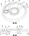
- the seat carrier subassembly 460 ( FIGS. 4A and 4B ) includes a seat carrier body 461 defining an annular seat recess 464 and inner and outer wall portions 465, 467 retaining a valve seat 440, and first and second flow apertures 466, 468 aligned with (i.e., in direct fluid communication with) first and second fluid ports 436, 438 in the valve body 430.
- the seat carrier body 461 may include multiple second flow apertures 468, for example, to provide substantially consistent flow regardless of rotational orientation of the seat carrier subassembly within the valve body.
- a bonnet nut 410 assembled with the valve body 430 applies a clamping force to an outer periphery of the diaphragm 426 and the seat carrier body 461 to seal the diaphragm against the seat carrier body, and to seal the outer periphery of the seat carrier body against an outer periphery of the seating surface 433.
- the diaphragm 426 may be welded to the outer periphery of the seat carrier body 461 to ensure a seal between the seat carrier body and the diaphragm, and to provide the diaphragm as part of the seat carrier subassembly.
- the exemplary seat carrier subassembly 460 further includes a body seal 470 (e.g., a plastic or polymeric seal ring) retained (e.g., staked or press fit) in an annular groove 463 in the seat carrier body 461 to seal against a body cavity surface 439 surrounding the first fluid port 436 of the valve body 430.
- a body seal 470 e.g., a plastic or polymeric seal ring
- retained e.g., staked or press fit
- a valve seat 440 includes an internal counterbore or shoulder 442 that receives a flow restricting orifice disc or insert 445, for example, as a press fit subassembly.
- a flow restricting orifice disc or insert 445 for example, as a press fit subassembly.
- FIG. 5 illustrates an actuated valve assembly 500, similar to the actuated valve assembly 400 of FIG. 4 , but with the seat carrier subassembly 560 including an orifice restriction 544 assembled with the annular inner wall portion 565, inward of the valve seat retaining recess 564 and surrounding the first flow aperture 566. While the orifice restriction may be provided as a single piece component to be assembled with the inner wall portion, in the illustrated example, an orifice carrier 546 retaining a flow restricting orifice disc 545 (which may, but need not, be similar to the orifice carrier 246 and disc 245 arrangement shown in FIGS. 2 and 2A and described above) is assembled with the inner wall portion 565, for example, with an outer peripheral step or shoulder 549 seated against an inner peripheral recess 569 of the inner wall portion.
- the seat carrier subassembly 560 ( FIGS. 5A and 5B ) includes a seat carrier body 561 defining an annular seat recess 564 and inner and outer wall portions 565, 567 retaining a valve seat 540, and first and second flow apertures 566, 568 aligned with (i.e., in direct fluid communication with) first and second fluid ports 536, 538 in the valve body 530.
- the seat carrier body 561 may include multiple second flow apertures 568, for example, to provide substantially consistent flow regardless of rotational orientation of the seat carrier subassembly within the valve body.
- a bonnet nut 510 assembled with the valve body 530 applies a clamping force to an outer periphery of the diaphragm 526 and the seat carrier body 561 to seal the diaphragm against the seat carrier body, and to seal the outer periphery of the seat carrier body against an outer periphery of the seating surface 533.
- the diaphragm 526 may be welded to the outer periphery of the seat carrier body 561 to ensure a seal between the seat carrier body and the diaphragm, and to provide the diaphragm as part of the seat carrier subassembly.
- the exemplary seat carrier subassembly 560 further includes a body seal 570 (e.g., a plastic or polymeric seal ring) retained (e.g., staked or press fit) in an annular groove 563 in the seat carrier body 561 to seal against a body cavity surface 539 surrounding the first fluid port 536 of the valve body 530.
- a body seal 570 e.g., a plastic or polymeric seal ring
- retained e.g., staked or press fit
- the valve seat 540 may be staked, crimped, or otherwise installed into the annular seat recess 564, for example, with the outer wall portion 567 staked or crimped radially inward to securely retain the valve seat 540.
- FIG. 5C illustrates a seat carrier subassembly 560' including an orifice restriction 544' (which may be consistent with the orifice restriction 244' of FIGS.
- the substantially cylindrical outer periphery 549' of the orifice carrier 546' welded with an interior portion of an annular inner wall portion 565' of the seat carrier body 561', inward of the valve seat 540' and surrounding the first flow aperture 566'.
- the cylindrical outer periphery 549' of the orifice carrier 546' may be seated against an inner peripheral recess or counterbore 569' of the inner wall portion 565' and welded (at annular weld bead 501') to the annular inner wall portion 565', for example, to securely and sealingly retain the orifice restriction 244' with the seat carrier body 561'.
- the weld bead 501' may extend along the entire junction between the counterbore portion 569' and the cylindrical outer periphery 549' (e.g., through to the base flange portion of the counterbore), or only a portion of the junction sufficient to eliminate any crevice or seam between the orifice carrier 546' and the annular inner wall portion 565'.
- FIG. 6 illustrates an actuated valve assembly 600, similar to the actuated valve assembly 500 of FIG. 5 , but with an orifice restriction 644 assembled with an interior portion of an annular inner wall portion at the second flow aperture 668 of the seat carrier 660.
- the seat carrier subassembly 660 ( FIGS. 6A and 6B ) includes a seat carrier body 661 defining an annular seat recess 664 and inner and outer wall portions 665, 667 retaining a valve seat 640, and first and second flow apertures 666, 668 aligned with (i.e., in direct fluid communication with) first and second fluid ports 636, 638 in the valve body 630.
- the seat carrier body 661 may include multiple second flow apertures 668, for example, to provide substantially consistent flow regardless of rotational orientation of the seat carrier subassembly within the valve body.
- a bonnet nut 610 assembled with the valve body 630 applies a clamping force to an outer periphery of the diaphragm 626 and the seat carrier body 661 to seal the diaphragm against the seat carrier body, and to seal the outer periphery of the seat carrier body against an outer periphery of the seating surface 633.
- the diaphragm 626 may be welded to the outer periphery of the seat carrier body 661 to ensure a seal between the seat carrier body and the diaphragm, and to provide the diaphragm as part of the seat carrier subassembly.
- the exemplary seat carrier subassembly 660 further includes a body seal 670 (e.g., a plastic or polymeric seal ring) retained (e.g., staked or press fit) in an annular groove 663 in the seat carrier body 661 to seal against a body cavity surface 639 surrounding the first fluid port 636 of the valve body 630.
- a body seal 670 e.g., a plastic or polymeric seal ring
- retained e.g., staked or press fit
- an orifice carrier 646 retaining a flow restricting orifice disc 645 (which may, but need not, be similar to the orifice carrier 246 and disc 245 arrangement shown in FIG. 2 and described above) is assembled with the inner wall portion 665, for example, with an outer peripheral step or shoulder 649 seated against an inner peripheral recess 669 of the inner wall portion.
- an orifice carrier may be adapted to permit removal from, and replacement in, the seat carrier, for example, without removing the valve seat and/or body seal, and/or with a diaphragm welded to the seat carrier.
- a plastic (e.g., perfluoroalkoxy alkane, or PFA) orifice carrier may be sized to be removably inserted (e.g., press fit) into a central flow aperture in the seat carrier, with an orifice disc installed (e.g., press fit) in a central bore of the orifice carrier.
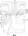
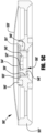
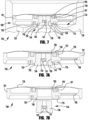
- FIG. 7 illustrates a valve assembly 700 including a seat carrier subassembly 760 including an orifice restriction 744 assembled with a first, central flow aperture 766 in the seat carrier body 761. While the orifice restriction may be provided as a single piece component to be assembled with the first flow aperture 766, in the illustrated example, a plastic (e.g., PFA) orifice carrier 746 retaining a flow restricting orifice disc 745, press fit into the central bore 747 of the orifice carrier, is press fit into the first flow port 766. As shown in FIGS.
- PFA plastic
- the orifice carrier 746 may, but need not, extend into alignment with the annular inner wall portion 765, for example, to provide an extended surface of press fit engagement between the seat carrier body 761 and the orifice carrier.
- the orifice carrier 746 may include an outer shoulder (e.g., chamfered shoulder) 749 that engages a surface (e.g., inner chamfer) 762 of the first flow aperture 766 for proper axial alignment of the orifice carrier 746 in the seat carrier body 761.
- a distal end 741 of the orifice carrier 746 may be sized to extend beyond the body engaging end of the seat carrier body 761, and into the first fluid port 736 of the valve body 730, for example, to facilitate user grasping and removal of the orifice carrier 746 from a removed seat carrier subassembly 760.
- FIG. 8 illustrates an exemplary seat carrier subassembly 860 for use in a valve assembly (e.g., the valve assembly of any of FIGS. 4 , 5 , 6 , and 7 ).
- the seat carrier subassembly 860 includes a flow restricting orifice disc or insert 845 received in an inner peripheral upper counterbore or recess 869 surrounding a first, central flow aperture 866 in a seat carrier body 861, and surrounded by an upper valve seat 840 and a lower body seal 870.
- the orifice disc 845 is staked or press fit into the inner peripheral recess 869 to provide an interference fit between the orifice disk and the seat carrier body 861.
- a flow restricting orifice disc or insert may be staked or press fit into an inner peripheral lower counterbore or recess surrounding a first, central flow aperture, or into an inner peripheral upper or lower counterbore or recess surrounding a second, offset flow aperture.
- the orifice disc 945 is captured in the inner peripheral recess 969 by an annular weld ring 980 received in an outer peripheral lower counterbore or recess 962 in the seat carrier body 961, and welded with the seat carrier body by an annular weld bead 981 penetrating the seat carrier body and weld ring from an upper, diaphragm facing surface of the seat carrier body. As shown, the full penetration of the weld bead 981 may prevent any crevices between the outer peripheral recess 962 and the seat carrier body 961.
- an axial load applied to the weld ring 980 against the orifice disc 945 may prevent leakage between the weld ring and the orifice restriction, and may provide for flexed, live loaded engagement between an inner lip portion 969a of the seat carrier body 961 and the orifice disc.
- a flow restricting orifice disc or insert may be similarly retained in an inner peripheral lower counterbore or recess surrounding a second, offset flow aperture in the seat carrier body.
- FIG. 10 illustrates another exemplary seat carrier subassembly 1060 for use in a valve assembly (e.g., the valve assembly of any of FIGS. 4 , 5 , 6 , and 7 ).
- the seat carrier subassembly 1060 includes a flow restricting orifice disc or insert 1045 received in an inner peripheral upper counterbore or recess 1069 surrounding a first, central flow aperture 1066 in a seat carrier body 1061, and surrounded by an upper valve seat 1040 and a lower body seal 1070.
- the orifice disc 1045 is captured in the inner peripheral recess 1069 by an annular weld ring or disc 1080 received in an outer peripheral upper counterbore or recess 1062 in the seat carrier body 1061, and welded with the seat carrier body by an annular weld bead 1081 penetrating the weld ring and seat carrier body from an upper, diaphragm facing surface of the seat carrier body. As shown, the full penetration of the weld bead 1081 may prevent any crevices between the outer peripheral recess 1062 and the seat carrier body 1061.
- the orifice disc 1145 is captured in the inner peripheral recess 1139 by an annular weld ring or disc 1180 received in an outer peripheral upper counterbore or recess 1132 in the valve body 1130, and welded with the valve body by an annular weld bead 1181 penetrating the weld ring and valve body from an upper, diaphragm facing surface of the valve body.
- an annular weld bead 1181 penetrating the weld ring and valve body from an upper, diaphragm facing surface of the valve body.
- the full penetration of the weld bead 1181 may prevent any crevices between the outer peripheral recess 1132 and the valve body 1130.
- the weld operation may cause the relatively thin annular weld ring or disc 1180 to flex against the orifice disc 1145, for example, to provide for flexed, live loaded engagement between the weld ring and the orifice restriction.
Landscapes
- Engineering & Computer Science (AREA)
- General Engineering & Computer Science (AREA)
- Mechanical Engineering (AREA)
- Physics & Mathematics (AREA)
- Fluid Mechanics (AREA)
- Lift Valve (AREA)
- Valve Housings (AREA)
- Multiple-Way Valves (AREA)
Priority Applications (1)
| Application Number | Priority Date | Filing Date | Title |
|---|---|---|---|
| EP25158054.4A EP4530512A3 (en) | 2020-11-04 | 2021-11-02 | Valves with integrated orifice restrictions |
Applications Claiming Priority (2)
| Application Number | Priority Date | Filing Date | Title |
|---|---|---|---|
| US202063109496P | 2020-11-04 | 2020-11-04 | |
| PCT/US2021/057663 WO2022098620A1 (en) | 2020-11-04 | 2021-11-02 | Valves with integrated orifice restrictions |
Related Child Applications (2)
| Application Number | Title | Priority Date | Filing Date |
|---|---|---|---|
| EP25158054.4A Division EP4530512A3 (en) | 2020-11-04 | 2021-11-02 | Valves with integrated orifice restrictions |
| EP25158054.4A Division-Into EP4530512A3 (en) | 2020-11-04 | 2021-11-02 | Valves with integrated orifice restrictions |
Publications (3)
| Publication Number | Publication Date |
|---|---|
| EP4240997A1 EP4240997A1 (en) | 2023-09-13 |
| EP4240997C0 EP4240997C0 (en) | 2025-04-02 |
| EP4240997B1 true EP4240997B1 (en) | 2025-04-02 |
Family
ID=78819637
Family Applications (2)
| Application Number | Title | Priority Date | Filing Date |
|---|---|---|---|
| EP21816233.7A Active EP4240997B1 (en) | 2020-11-04 | 2021-11-02 | Valves with integrated orifice restrictions |
| EP25158054.4A Withdrawn EP4530512A3 (en) | 2020-11-04 | 2021-11-02 | Valves with integrated orifice restrictions |
Family Applications After (1)
| Application Number | Title | Priority Date | Filing Date |
|---|---|---|---|
| EP25158054.4A Withdrawn EP4530512A3 (en) | 2020-11-04 | 2021-11-02 | Valves with integrated orifice restrictions |
Country Status (7)
| Country | Link |
|---|---|
| US (2) | US11808381B2 (https=) |
| EP (2) | EP4240997B1 (https=) |
| JP (1) | JP2023548331A (https=) |
| KR (1) | KR20230094191A (https=) |
| CN (1) | CN116490710A (https=) |
| TW (1) | TWI900687B (https=) |
| WO (1) | WO2022098620A1 (https=) |
Families Citing this family (3)
| Publication number | Priority date | Publication date | Assignee | Title |
|---|---|---|---|---|
| WO2021101855A1 (en) * | 2019-11-18 | 2021-05-27 | Swagelok Company | Arrangements and methods for controlled valve flow rate |
| US11761547B1 (en) * | 2022-04-07 | 2023-09-19 | Horiba Stec, Co., Ltd. | Valve orifice insert |
| JP7655884B2 (ja) * | 2022-05-24 | 2025-04-02 | Ckd株式会社 | 流体制御弁およびその製造方法 |
Family Cites Families (53)
| Publication number | Priority date | Publication date | Assignee | Title |
|---|---|---|---|---|
| US4516606A (en) * | 1983-02-16 | 1985-05-14 | Exxon Research And Engineering Co. | Variable orifice valve assembly |
| US5334864A (en) | 1987-03-26 | 1994-08-02 | Canon Kabushiki Kaisha | Process for selective formation of II-VI group compound film |
| US5335691A (en) | 1992-05-26 | 1994-08-09 | Nupro Company | High pressure diaphragm valve |
| US5314164A (en) | 1992-07-17 | 1994-05-24 | Mks Instruments, Inc. | Pivotal diaphragm, flow control valve |
| DE19638201B4 (de) | 1996-09-19 | 2005-05-04 | Robert Bosch Gmbh | Brennstoffeinspritzventil |
| DE19653832A1 (de) | 1996-12-21 | 1998-06-25 | Bosch Gmbh Robert | Ventil mit kombiniertem Ventilsitzkörper und Spritzlochscheibe |
| JP3941844B2 (ja) * | 1997-06-03 | 2007-07-04 | シーケーディ株式会社 | ガス制御バルブ |
| US6000416A (en) | 1997-06-04 | 1999-12-14 | Furon Company | Compact valve with rolling diaphragm poppet |
| DE19736682A1 (de) | 1997-08-22 | 1999-02-25 | Bosch Gmbh Robert | Brennstoffeinspritzventil |
| US5881997A (en) | 1997-11-24 | 1999-03-16 | Fujikin Incorporated | Metal diaphragm type valve |
| US5909747A (en) | 1998-04-03 | 1999-06-08 | American Meter Company | Radial flow diaphragm valve |
| JP3522535B2 (ja) | 1998-05-29 | 2004-04-26 | 忠弘 大見 | 圧力式流量制御装置を備えたガス供給設備 |
| JP3502561B2 (ja) | 1999-02-22 | 2004-03-02 | Smc株式会社 | レギュレーター |
| DE19946838C1 (de) | 1999-09-30 | 2000-10-19 | Bosch Gmbh Robert | Ventil zum Steuern von Flüssigkeiten |
| KR100426709B1 (ko) | 2000-06-05 | 2004-04-14 | 가부시키가이샤 후지킨 | 오리피스 내장밸브 |
| CA2370819C (en) | 2001-02-09 | 2005-07-26 | Jennmar Corporation | Cable bolt with mixing delay device |
| US20030042459A1 (en) | 2001-08-29 | 2003-03-06 | Gregoire Roger J. | Unitary diaphragm and seat assembly |
| JP4197627B2 (ja) | 2003-06-02 | 2008-12-17 | シーケーディ株式会社 | ガスレギュレータ |
| JP3861206B2 (ja) | 2003-12-08 | 2006-12-20 | 株式会社フジキン | 流体制御器 |
| JP2005188672A (ja) | 2003-12-26 | 2005-07-14 | Neriki:Kk | バルブ装置 |
| EP1721227A4 (en) | 2004-02-27 | 2010-02-03 | Horiba Stec Co Ltd | THROTTLE BODY |
| DE102004033280A1 (de) | 2004-07-09 | 2006-02-02 | Robert Bosch Gmbh | Einspritzventil zur Kraftstoffeinspritzung |
| JP2006090386A (ja) | 2004-09-22 | 2006-04-06 | Kitz Sct:Kk | ダイヤフラムバルブ |
| CN2812071Y (zh) * | 2005-07-18 | 2006-08-30 | 西安交通大学 | 一种带接头的节流元件 |
| JP4549981B2 (ja) | 2006-01-27 | 2010-09-22 | 株式会社キッツエスシーティー | 流体制御機器 |
| JP4256884B2 (ja) | 2006-06-23 | 2009-04-22 | 東京エレクトロン株式会社 | 気化器への原料液供給ユニット |
| EP2003379A1 (en) | 2007-06-12 | 2008-12-17 | Luxembourg Patent Company S.A. | High pressure diaphragm valve with exchangeable seat assembly |
| WO2011163210A1 (en) | 2010-06-22 | 2011-12-29 | Swagelok Company | Clamp ring for welded diaphragms |
| DE102010064268A1 (de) | 2010-12-28 | 2012-06-28 | Robert Bosch Gmbh | Einspritzventil |
| DE102012211665A1 (de) | 2011-08-18 | 2013-02-21 | Robert Bosch Gmbh | Ventil für ein strömendes Fluid |
| US9188989B1 (en) | 2011-08-20 | 2015-11-17 | Daniel T. Mudd | Flow node to deliver process gas using a remote pressure measurement device |
| US9863542B2 (en) * | 2013-02-01 | 2018-01-09 | Swagelok Company | Diaphragm valve with welded diaphragm seat carrier |
| JP6141663B2 (ja) | 2013-03-27 | 2017-06-07 | 株式会社堀場エステック | 流体制御弁 |
| EP2792902B1 (en) | 2013-04-16 | 2016-09-07 | Öhlins Racing Ab | Valve arrangement |
| JP6072648B2 (ja) | 2013-08-12 | 2017-02-01 | 株式会社フジキン | ダイヤフラム弁 |
| JP6335685B2 (ja) | 2014-06-30 | 2018-05-30 | 株式会社フジキン | ダイヤフラム弁、流体制御装置、半導体製造装置および半導体製造方法 |
| JP6602553B2 (ja) | 2015-04-30 | 2019-11-06 | Ckd株式会社 | ダイアフラム、流体制御装置、及びダイアフラムの製造方法 |
| JP6216738B2 (ja) | 2015-05-26 | 2017-10-18 | Ckd株式会社 | パイロット式電磁弁 |
| US10781892B2 (en) | 2015-07-31 | 2020-09-22 | Borgwarner Inc. | Press-fit check valve for a hydraulic tensioner reservoir with metered backflow |
| WO2018021277A1 (ja) | 2016-07-29 | 2018-02-01 | 株式会社フジキン | オリフィス内蔵弁および圧力式流量制御装置 |
| CN110114601B (zh) | 2016-12-26 | 2020-10-27 | 株式会社富士金 | 压电元件驱动式阀以及流量控制装置 |
| JP6929098B2 (ja) * | 2017-03-30 | 2021-09-01 | 株式会社キッツエスシーティー | メタルダイヤフラムバルブ |
| US10982633B2 (en) | 2017-07-03 | 2021-04-20 | Continental Automotive Systems, Inc. | Fuel pump solenoid assembly method |
| WO2019047916A1 (zh) | 2017-09-08 | 2019-03-14 | 江苏科维仪表控制工程有限公司 | 密封性优越式手动高温高压疏水球阀 |
| US11162597B2 (en) * | 2017-10-31 | 2021-11-02 | Fujikin Incorporated | Flow path assembly and valve device |
| US11231026B2 (en) | 2017-10-31 | 2022-01-25 | Fujikin Incorporated | Valve device |
| CN111417809A (zh) * | 2017-11-30 | 2020-07-14 | 株式会社富士金 | 阀装置、使用该阀装置的流体控制装置以及半导体制造装置 |
| US10877495B2 (en) | 2018-03-08 | 2020-12-29 | Emerson Process Management Regulator Technologies, Inc. | Pressure loaded regulator with dual diaphragm and redundant seal |
| US11402029B2 (en) | 2018-04-06 | 2022-08-02 | Fujikin Incorporated | Valve device, fluid control system, fluid control method, semiconductor manufacturing system, and semiconductor manufacturing method |
| KR102499250B1 (ko) | 2018-09-25 | 2023-02-10 | 가부시키가이샤 후지킨 | 밸브 |
| JP2020204369A (ja) | 2019-06-18 | 2020-12-24 | Ckd株式会社 | ダイアフラムバルブの製造方法 |
| JP2021021408A (ja) | 2019-07-25 | 2021-02-18 | 株式会社ノーリツ | 流量調整弁 |
| WO2021101855A1 (en) | 2019-11-18 | 2021-05-27 | Swagelok Company | Arrangements and methods for controlled valve flow rate |
-
2021
- 2021-11-02 JP JP2023526458A patent/JP2023548331A/ja active Pending
- 2021-11-02 WO PCT/US2021/057663 patent/WO2022098620A1/en not_active Ceased
- 2021-11-02 EP EP21816233.7A patent/EP4240997B1/en active Active
- 2021-11-02 US US17/517,317 patent/US11808381B2/en active Active
- 2021-11-02 KR KR1020237016083A patent/KR20230094191A/ko active Pending
- 2021-11-02 CN CN202180074394.3A patent/CN116490710A/zh active Pending
- 2021-11-02 EP EP25158054.4A patent/EP4530512A3/en not_active Withdrawn
- 2021-11-03 TW TW110141020A patent/TWI900687B/zh active
-
2023
- 2023-09-25 US US18/473,835 patent/US12203568B2/en active Active
Also Published As
| Publication number | Publication date |
|---|---|
| US20240019034A1 (en) | 2024-01-18 |
| JP2023548331A (ja) | 2023-11-16 |
| EP4530512A2 (en) | 2025-04-02 |
| US12203568B2 (en) | 2025-01-21 |
| WO2022098620A1 (en) | 2022-05-12 |
| EP4240997A1 (en) | 2023-09-13 |
| US11808381B2 (en) | 2023-11-07 |
| EP4240997C0 (en) | 2025-04-02 |
| KR20230094191A (ko) | 2023-06-27 |
| EP4530512A3 (en) | 2025-05-14 |
| US20220136610A1 (en) | 2022-05-05 |
| TWI900687B (zh) | 2025-10-11 |
| TW202227738A (zh) | 2022-07-16 |
| CN116490710A (zh) | 2023-07-25 |
Similar Documents
| Publication | Publication Date | Title |
|---|---|---|
| US12203568B2 (en) | Valves with integrated orifice restrictions | |
| US9133942B2 (en) | Valve structure for fluid pressure device | |
| EP2598778B1 (en) | Valve seat apparatus for use with fluid valves | |
| EP2250410B1 (en) | Dual seating quick connect valve | |
| EP0892204B1 (en) | Improved diaphragm valve with leak detection | |
| US7610928B2 (en) | Valve and actuator assemblies | |
| MX2010007617A (es) | Ensamble de sello para uso con valvulas que tienen una jaula de dos piezas. | |
| EP3027940B1 (en) | Fluid valve apparatus having enclosed seals | |
| WO2009088633A1 (en) | Control valve trim and seal | |
| EP4240998B1 (en) | Valve cavity cap arrangements | |
| US7258133B2 (en) | Pressure reducing valve | |
| US11162597B2 (en) | Flow path assembly and valve device | |
| KR20240013881A (ko) | 밸브 장치 | |
| WO2020085302A1 (ja) | バルブ装置およびガス供給システム |
Legal Events
| Date | Code | Title | Description |
|---|---|---|---|
| STAA | Information on the status of an ep patent application or granted ep patent |
Free format text: STATUS: UNKNOWN |
|
| STAA | Information on the status of an ep patent application or granted ep patent |
Free format text: STATUS: THE INTERNATIONAL PUBLICATION HAS BEEN MADE |
|
| PUAI | Public reference made under article 153(3) epc to a published international application that has entered the european phase |
Free format text: ORIGINAL CODE: 0009012 |
|
| STAA | Information on the status of an ep patent application or granted ep patent |
Free format text: STATUS: REQUEST FOR EXAMINATION WAS MADE |
|
| 17P | Request for examination filed |
Effective date: 20230404 |
|
| AK | Designated contracting states |
Kind code of ref document: A1 Designated state(s): AL AT BE BG CH CY CZ DE DK EE ES FI FR GB GR HR HU IE IS IT LI LT LU LV MC MK MT NL NO PL PT RO RS SE SI SK SM TR |
|
| DAV | Request for validation of the european patent (deleted) | ||
| DAX | Request for extension of the european patent (deleted) | ||
| GRAP | Despatch of communication of intention to grant a patent |
Free format text: ORIGINAL CODE: EPIDOSNIGR1 |
|
| STAA | Information on the status of an ep patent application or granted ep patent |
Free format text: STATUS: GRANT OF PATENT IS INTENDED |
|
| INTG | Intention to grant announced |
Effective date: 20241205 |
|
| GRAS | Grant fee paid |
Free format text: ORIGINAL CODE: EPIDOSNIGR3 |
|
| GRAA | (expected) grant |
Free format text: ORIGINAL CODE: 0009210 |
|
| STAA | Information on the status of an ep patent application or granted ep patent |
Free format text: STATUS: THE PATENT HAS BEEN GRANTED |
|
| AK | Designated contracting states |
Kind code of ref document: B1 Designated state(s): AL AT BE BG CH CY CZ DE DK EE ES FI FR GB GR HR HU IE IS IT LI LT LU LV MC MK MT NL NO PL PT RO RS SE SI SK SM TR |
|
| REG | Reference to a national code |
Ref country code: GB Ref legal event code: FG4D |
|
| REG | Reference to a national code |
Ref country code: CH Ref legal event code: EP |
|
| REG | Reference to a national code |
Ref country code: IE Ref legal event code: FG4D |
|
| REG | Reference to a national code |
Ref country code: DE Ref legal event code: R096 Ref document number: 602021028638 Country of ref document: DE |
|
| U01 | Request for unitary effect filed |
Effective date: 20250416 |
|
| U07 | Unitary effect registered |
Designated state(s): AT BE BG DE DK EE FI FR IT LT LU LV MT NL PT RO SE SI Effective date: 20250424 |
|
| PG25 | Lapsed in a contracting state [announced via postgrant information from national office to epo] |
Ref country code: ES Free format text: LAPSE BECAUSE OF FAILURE TO SUBMIT A TRANSLATION OF THE DESCRIPTION OR TO PAY THE FEE WITHIN THE PRESCRIBED TIME-LIMIT Effective date: 20250402 |
|
| PG25 | Lapsed in a contracting state [announced via postgrant information from national office to epo] |
Ref country code: NO Free format text: LAPSE BECAUSE OF FAILURE TO SUBMIT A TRANSLATION OF THE DESCRIPTION OR TO PAY THE FEE WITHIN THE PRESCRIBED TIME-LIMIT Effective date: 20250702 Ref country code: GR Free format text: LAPSE BECAUSE OF FAILURE TO SUBMIT A TRANSLATION OF THE DESCRIPTION OR TO PAY THE FEE WITHIN THE PRESCRIBED TIME-LIMIT Effective date: 20250703 |
|
| PG25 | Lapsed in a contracting state [announced via postgrant information from national office to epo] |
Ref country code: PL Free format text: LAPSE BECAUSE OF FAILURE TO SUBMIT A TRANSLATION OF THE DESCRIPTION OR TO PAY THE FEE WITHIN THE PRESCRIBED TIME-LIMIT Effective date: 20250402 |
|
| PG25 | Lapsed in a contracting state [announced via postgrant information from national office to epo] |
Ref country code: HR Free format text: LAPSE BECAUSE OF FAILURE TO SUBMIT A TRANSLATION OF THE DESCRIPTION OR TO PAY THE FEE WITHIN THE PRESCRIBED TIME-LIMIT Effective date: 20250402 |
|
| PG25 | Lapsed in a contracting state [announced via postgrant information from national office to epo] |
Ref country code: RS Free format text: LAPSE BECAUSE OF FAILURE TO SUBMIT A TRANSLATION OF THE DESCRIPTION OR TO PAY THE FEE WITHIN THE PRESCRIBED TIME-LIMIT Effective date: 20250702 |
|
| PG25 | Lapsed in a contracting state [announced via postgrant information from national office to epo] |
Ref country code: IS Free format text: LAPSE BECAUSE OF FAILURE TO SUBMIT A TRANSLATION OF THE DESCRIPTION OR TO PAY THE FEE WITHIN THE PRESCRIBED TIME-LIMIT Effective date: 20250802 |
|
| U20 | Renewal fee for the european patent with unitary effect paid |
Year of fee payment: 5 Effective date: 20251126 |
|
| PGFP | Annual fee paid to national office [announced via postgrant information from national office to epo] |
Ref country code: GB Payment date: 20251127 Year of fee payment: 5 |
|
| PG25 | Lapsed in a contracting state [announced via postgrant information from national office to epo] |
Ref country code: SM Free format text: LAPSE BECAUSE OF FAILURE TO SUBMIT A TRANSLATION OF THE DESCRIPTION OR TO PAY THE FEE WITHIN THE PRESCRIBED TIME-LIMIT Effective date: 20250402 |
|
| PG25 | Lapsed in a contracting state [announced via postgrant information from national office to epo] |
Ref country code: CZ Free format text: LAPSE BECAUSE OF FAILURE TO SUBMIT A TRANSLATION OF THE DESCRIPTION OR TO PAY THE FEE WITHIN THE PRESCRIBED TIME-LIMIT Effective date: 20250402 |
|
| PGFP | Annual fee paid to national office [announced via postgrant information from national office to epo] |
Ref country code: IE Payment date: 20251127 Year of fee payment: 5 |
|
| PG25 | Lapsed in a contracting state [announced via postgrant information from national office to epo] |
Ref country code: SK Free format text: LAPSE BECAUSE OF FAILURE TO SUBMIT A TRANSLATION OF THE DESCRIPTION OR TO PAY THE FEE WITHIN THE PRESCRIBED TIME-LIMIT Effective date: 20250402 |
|
| PLBE | No opposition filed within time limit |
Free format text: ORIGINAL CODE: 0009261 |
|
| STAA | Information on the status of an ep patent application or granted ep patent |
Free format text: STATUS: NO OPPOSITION FILED WITHIN TIME LIMIT |
|
| REG | Reference to a national code |
Ref country code: CH Ref legal event code: L10 Free format text: ST27 STATUS EVENT CODE: U-0-0-L10-L00 (AS PROVIDED BY THE NATIONAL OFFICE) Effective date: 20260211 |
|
| 26N | No opposition filed |
Effective date: 20260105 |