EP4225518B1 - Blechtafel mit erhöhten bereichen zur erzeugung eines industriefussbodens mit verbesserten hafteigenschaften - Google Patents
Blechtafel mit erhöhten bereichen zur erzeugung eines industriefussbodens mit verbesserten hafteigenschaften Download PDFInfo
- Publication number
- EP4225518B1 EP4225518B1 EP21799312.0A EP21799312A EP4225518B1 EP 4225518 B1 EP4225518 B1 EP 4225518B1 EP 21799312 A EP21799312 A EP 21799312A EP 4225518 B1 EP4225518 B1 EP 4225518B1
- Authority
- EP
- European Patent Office
- Prior art keywords
- sheet metal
- metal plate
- rolling
- lower face
- roughness
- Prior art date
- Legal status (The legal status is an assumption and is not a legal conclusion. Google has not performed a legal analysis and makes no representation as to the accuracy of the status listed.)
- Active
Links
Images


Classifications
-
- B—PERFORMING OPERATIONS; TRANSPORTING
- B21—MECHANICAL METAL-WORKING WITHOUT ESSENTIALLY REMOVING MATERIAL; PUNCHING METAL
- B21H—MAKING PARTICULAR METAL OBJECTS BY ROLLING, e.g. SCREWS, WHEELS, RINGS, BARRELS, BALLS
- B21H8/00—Rolling metal of indefinite length in repetitive shapes specially designed for the manufacture of particular objects, e.g. checkered sheets
- B21H8/005—Embossing sheets or rolls
-
- B—PERFORMING OPERATIONS; TRANSPORTING
- B21—MECHANICAL METAL-WORKING WITHOUT ESSENTIALLY REMOVING MATERIAL; PUNCHING METAL
- B21B—ROLLING OF METAL
- B21B1/00—Metal-rolling methods or mills for making semi-finished products of solid or profiled cross-section; Sequence of operations in milling trains; Layout of rolling-mill plant, e.g. grouping of stands; Succession of passes or of sectional pass alternations
- B21B1/22—Metal-rolling methods or mills for making semi-finished products of solid or profiled cross-section; Sequence of operations in milling trains; Layout of rolling-mill plant, e.g. grouping of stands; Succession of passes or of sectional pass alternations for rolling plates, strips, bands or sheets of indefinite length
- B21B1/227—Surface roughening or texturing
-
- B—PERFORMING OPERATIONS; TRANSPORTING
- B21—MECHANICAL METAL-WORKING WITHOUT ESSENTIALLY REMOVING MATERIAL; PUNCHING METAL
- B21B—ROLLING OF METAL
- B21B1/00—Metal-rolling methods or mills for making semi-finished products of solid or profiled cross-section; Sequence of operations in milling trains; Layout of rolling-mill plant, e.g. grouping of stands; Succession of passes or of sectional pass alternations
- B21B1/22—Metal-rolling methods or mills for making semi-finished products of solid or profiled cross-section; Sequence of operations in milling trains; Layout of rolling-mill plant, e.g. grouping of stands; Succession of passes or of sectional pass alternations for rolling plates, strips, bands or sheets of indefinite length
- B21B2001/225—Metal-rolling methods or mills for making semi-finished products of solid or profiled cross-section; Sequence of operations in milling trains; Layout of rolling-mill plant, e.g. grouping of stands; Succession of passes or of sectional pass alternations for rolling plates, strips, bands or sheets of indefinite length by hot-rolling
-
- B—PERFORMING OPERATIONS; TRANSPORTING
- B21—MECHANICAL METAL-WORKING WITHOUT ESSENTIALLY REMOVING MATERIAL; PUNCHING METAL
- B21B—ROLLING OF METAL
- B21B3/00—Rolling materials of special alloys so far as the composition of the alloy requires or permits special rolling methods or sequences ; Rolling of aluminium, copper, zinc or other non-ferrous metals
- B21B2003/001—Aluminium or its alloys
-
- B—PERFORMING OPERATIONS; TRANSPORTING
- B21—MECHANICAL METAL-WORKING WITHOUT ESSENTIALLY REMOVING MATERIAL; PUNCHING METAL
- B21B—ROLLING OF METAL
- B21B2205/00—Particular shaped rolled products
-
- B—PERFORMING OPERATIONS; TRANSPORTING
- B21—MECHANICAL METAL-WORKING WITHOUT ESSENTIALLY REMOVING MATERIAL; PUNCHING METAL
- B21B—ROLLING OF METAL
- B21B2261/00—Product parameters
- B21B2261/14—Roughness
-
- B—PERFORMING OPERATIONS; TRANSPORTING
- B21—MECHANICAL METAL-WORKING WITHOUT ESSENTIALLY REMOVING MATERIAL; PUNCHING METAL
- B21B—ROLLING OF METAL
- B21B2267/00—Roll parameters
- B21B2267/10—Roughness of roll surface
-
- B—PERFORMING OPERATIONS; TRANSPORTING
- B44—DECORATIVE ARTS
- B44C—PRODUCING DECORATIVE EFFECTS; MOSAICS; TARSIA WORK; PAPERHANGING
- B44C1/00—Processes, not specifically provided for elsewhere, for producing decorative surface effects
- B44C1/24—Pressing or stamping ornamental designs on surfaces
-
- B—PERFORMING OPERATIONS; TRANSPORTING
- B44—DECORATIVE ARTS
- B44C—PRODUCING DECORATIVE EFFECTS; MOSAICS; TARSIA WORK; PAPERHANGING
- B44C5/00—Processes for producing special ornamental bodies
- B44C5/04—Ornamental plaques, e.g. decorative panels, decorative veneers
- B44C5/0415—Ornamental plaques, e.g. decorative panels, decorative veneers containing metallic elements
-
- B—PERFORMING OPERATIONS; TRANSPORTING
- B62—LAND VEHICLES FOR TRAVELLING OTHERWISE THAN ON RAILS
- B62D—MOTOR VEHICLES; TRAILERS
- B62D25/00—Superstructure or monocoque structure sub-units; Parts or details thereof not otherwise provided for
- B62D25/20—Floors or bottom sub-units
- B62D25/2054—Load carrying floors for commercial vehicles
Definitions
- the invention relates to a metal sheet for producing floors, in particular for industrial vehicles, having on one of its faces a plurality of relief patterns arranged periodically, each pattern itself being made up of one or more projecting parts, which we will call “reliefs”.
- This sheet is intended to be glued to a support, typically boards, to form the floor of the industrial vehicle.
- the term "relief sheet metal” refers to a sheet metal "printed with a relief pattern on one side, by rolling". These patterns are for example described in standard NF-EN-1386 and are often referred to in a figurative way (checkerboard, barley grain, almond, diamond, rice grain, checkerboard 2, checkerboard 5, etc.).
- the "checkerboard 5" pattern also called “quintet”, frequently used to make industrial floor sheets, has a group of 5 elongated bumps, half-ovoid in shape, parallel to each other, which is surrounded by four groups identical to each other and deduced from the first group by a 90° rotation.
- Figure 1 represents a relief sheet according to the EN1386 standard.
- the height of the relief pattern is the difference, h, between the maximum thickness measured up to the top of the pattern and the thickness t of the adjacent area without relief.
- the "rice grain” pattern described in the patent FR 2 747 948 , is also used for the production of aluminum alloy sheets for industrial floors, which have satisfactory operating properties, in particular because they have good wear resistance and offer frictional contact conditions which allow pedestrians to walk around without the risk of falling by slipping and trolleys to roll without skidding.
- the patent application WO2011/121191 which forms the basis for the preamble of claim 1, describes a metal sheet for the production of floors, in particular of industrial vehicles, on which trolleys must circulate, having a plurality of patterns, the reliefs of which have a maximum height of between 0.2 and 1.5 mm and a friction surface, which has, whatever the direction in which it is measured, an average width at least equal to 1 mm.
- the relief sheets have on the upper face, intended to form the floor and be in contact with people or handling vehicles used for example in industrial vehicles, said repetitive relief patterns.
- the patent application WO03/013752 describes a structure and associated methods having non-slip surfaces formed on projections, recesses or other surfaces of the structure to promote safe and stable movement of persons and/or objects on the structure.
- the patent application EP2316590 describes an embossed sheet with a repeating pattern having a plurality of pattern units.
- Each pattern unit includes one or more raised elongated reliefs, an elongated relief having a length along a major axis and a width less than the length along a minor axis perpendicular to the major axis.
- JPS59202103 describes the manufacture by rolling of strip or sheet having a continuous partially gridded pattern in the rolling direction.
- the patent application JPH03114601 describes the rolling of a single-sided embossed steel strip by measuring the thickness of the strip steel plate under rolling by a radiation thickness gauge and adjusting the draw of a rolling mill so that the difference of its average values becomes within a desired range.
- the lower face of the relief sheet is most often glued to a support, for example a wooden board typically made of plywood, to form the floor of the industrial vehicle.
- a surface treatment is carried out, according to the prior art, typically degreasing and the deposition of a primary adhesion layer such as typically a varnish. This treatment is effective, however it requires additional operations to be carried out which result in a high cost.
- the patent application JP2011069060A discloses a decorative sheet for a floor material, in which a transparent resin layer composed of a polypropylene resin layer is superimposed on a base material sheet, in which at least one transparent resin layer with a thickness of 150 ⁇ m or more is laminated to the base material sheet via an adhesive layer, is characterized as follows: (1) the transparent resin layer is composed of two or more polypropylene resin layers; and (2) the polypropylene resin layer, bonded to the base material sheet, among the two or more polypropylene resin layers, has a flexural rigidity of 200 to 500 MPa.
- the patent KR102147477B1 discloses a multi-purpose panel with improved adhesion and durability comprising a plurality of inner layer panels bonded by a bonding resin and an outer layer panel bonded to the upper and lower surfaces of the inner layer panel, respectively, in which a plurality of air holes are formed to penetrate in the width direction along the length direction.
- the utility model CN201933751U relates to a metal floor tile having a thickness of 1.5 to 5.5 mm.
- the metal floor tile comprises a panel and a rim formed by bending downward from the periphery of the panel, wherein a plurality of open holes are punched on the panel; one end of each open hole is downward to form an anchor bar connected to the panel; a plurality of through holes are punched on the rim; and one end of each through hole is inward to form a reinforcing bar connected to the rim.
- the problem that the present invention seeks to solve is to obtain a relief sheet exhibiting improved adhesion without requiring a surface treatment operation and deposition of a primer adhesion layer.
- a first subject of the invention is a metal sheet for producing floors, in particular for industrial vehicles, said sheet having on its upper face a plurality of relief patterns, each relief pattern comprising one or more projecting parts, said relief patterns being arranged in a periodic, discrete and orderly manner, the height h of said relief patterns being between 0.3 and 3 mm, characterized in that it has on its lower face, intended to be bonded to a support, a rough surface whose roughness R max is between 10 ⁇ m and 250 ⁇ m.
- Another object of the invention is the use of a metal sheet according to the invention for producing floors of industrial vehicles, preferably floors of refrigerated vehicles.
- the sheet metal according to the invention is a metal sheet intended to be bonded to a support to form the floor of a vehicle.
- a sheet metal is a rolled product with a generally rectangular cross-section whose average thickness does not exceed 1/10th of the width.
- the floor is the part of a construction or a vehicle which constitutes a horizontal platform, the upper face of which forms the ground.
- the roughness parameter R max is defined as the largest deviation between the highest peak and the lowest trough on the analyzed length or the analyzed surface.
- the analyzed length has a direction perpendicular to the rolling direction of the sheet metal and has a value depending on the R max value, as described below: 0.025 ⁇ m ⁇ R max ⁇ 0.1 ⁇ m typical analyzed length: 0.08 mm 0.1 ⁇ m ⁇ R max ⁇ 0.5 ⁇ m typical analyzed length: 0.25 mm 0.5 ⁇ m ⁇ R max ⁇ 10 ⁇ m typical analyzed length: 0.80 mm 10 ⁇ m ⁇ R max ⁇ 50 ⁇ m typical analyzed length: 2.50 mm 50 ⁇ m ⁇ R max ⁇ 250 ⁇ m typical analyzed length: 8.00 mm
- the R max parameter is notably mentioned in the BS 1134 2010 A2 standard in which the above definitions can be supplemented if necessary.
- the sheet metal according to the invention has on its upper face, intended to form the upper face of the floor, relief patterns which comprise one or more projecting parts and which, like the elementary mesh of a crystal lattice, are repeated in a periodic and orderly manner.
- a relief pattern is therefore a piece of sheet metal which is repeated indefinitely by translation in two directions of the plane of the sheet metal.
- This piece of sheet metal may comprise only one projecting part but it may also comprise several protruding parts which may have different shapes or orientations. It does not seem advantageous to have protruding parts of different heights but this is not a priori excluded.
- the height h of these relief patterns is between 0.3 mm and 3 mm.
- the height of the relief pattern is the difference, h, between the maximum thickness measured up to the top of the pattern and the thickness t of the adjacent area without relief.
- h the maximum thickness measured up to the top of the pattern
- t the thickness of the adjacent area without relief.
- Said patterns are also repeated in a discreet manner, since such a configuration is favorable to the non-slip property of the floor.
- the reliefs behave like indenters that act on the surface of the sole or tread of the wheel: under the effect of the weight of the pedestrian or the trolley, the latter deforms and "sinks" around the relief to a certain height, the order of magnitude of which is one, two or three tenths of a millimeter.
- a discontinuous relief promotes, in the sole or the tread, the formation of a bead all around its top wall, which promotes the "grip" of the sole, the tread or the tire of the wheel on the floor.
- the sheet according to the invention must therefore not have a continuous relief.
- the relief patterns on the upper face are obtained by rolling using an engraved rolling cylinder characterized in that it has engraved cavities allowing the relief patterns on the sheet to be obtained.
- the lower face of the sheet metal intended to be glued to a floor, has a rough surface whose roughness R max is between 10 ⁇ m and 250 ⁇ m and preferably between 50 ⁇ m and 150 ⁇ m, preferentially between 100 ⁇ m and 140 ⁇ m.
- the present inventor has found that thanks to the roughness of the lower face of the sheet metal, the adhesion between the floor, typically made of wood, and the metal sheet is satisfactory in the absence of surface treatment and primer deposition.
- the roughness according to the invention can be obtained in particular by electrochemical milling, mechanical milling, brushing, or by deformation typically sandblasting, shot peening, rolling, embossing, embossing.
- the roughness is obtained by rolling.
- the roughness of the lower face of the sheet metal is obtained by a texture, preferably produced by rolling.
- the sheet metal according to the invention has on its lower face a texture which comprises one or more projecting parts and which are repeated in a periodic and orderly manner. It does not seem advantageous to have projecting parts of different heights but this is not a priori excluded.
- the roughness R max of the lower face of the sheet metal corresponds to the maximum height of these projecting parts of the lower face.
- at least 30% and preferably at least 50% of the lower face of the sheet metal is covered by the texture and/or the dimension of the texture is between 1 and 6 mm and/or the reproduction pitch of the texture is between 1 and 6 mm.
- the metal sheet according to the invention is an aluminum alloy sheet.
- the sheet is made of an aluminum alloy belonging to the group comprising the aluminum alloys of the 1xxx, 3xxx, 5xxx, 6xxx series according to the designation of the Aluminum Association as well as the alloys of the 7xxx series, comprising less than 0.4% Cu.
- the alloy is selected from the list consisting of AA1050A, AA3003, AA3103, AA5026, AA5052, AA5083, AA5086, AA5754, AA6061, AA6082 and AA7020.
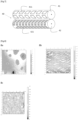
- FIG. 2 schematically represents a metal sheet 10 according to the invention having on its upper face 11 a relief pattern comprising a projecting part 20, of height h and on its lower face 12, a rough surface.
- FIG. 3 schematically represents a metal sheet 10 according to the invention in a preferred embodiment having on its upper face 11 a relief pattern comprising a projecting part 20, of height h and on its lower face 12, a rough surface consisting of a texture comprising projecting parts repeating periodically and in an orderly manner.
- FIG. 4 schematically represents a floor 30 comprising a metal sheet 10 according to the invention glued to a board 32 using an adhesive 31.
- the two steps are carried out simultaneously on a rolling mill comprising two engraved cylinders: a first engraved cylinder to obtain the relief patterns of the upper face and a second engraved cylinder to obtain the texture of the lower face.
- the two engraved cylinders are the working cylinders used during the last pass of a hot tandem rolling mill.
- a tandem rolling mill is a rolling mill comprising several successive stands, in which the product is engaged in several stands at the same time.
- FIG. 7 schematically represents the last stand 40 of a hot tandem rolling mill in this embodiment.
- the working rolls used 41, 42 are engraved rolls.
- a first engraved roll 41 has cavities 411 for obtaining the relief patterns of the upper face.
- a second engraved roll 42 has cavities 421 for obtaining the texture of the lower face of the sheet.
- the adhesion performance of a 2.5 mm thick AA5086 alloy sheet having a rice grain pattern relief as defined in standard NF EN 1386 on the upper face and a variable roughness on the lower face was compared.
- the lower face was as-rolled and the roughness R max was less than 3 ⁇ m.
- the lower face was textured with patterns having reliefs of different heights as described in Table 1. The textured patterns were obtained by rolling with an engraved cylinder. The same cylinder was used for samples B and C with a different clamping force so as to vary the depth of the imprint. These textures are shown in Figure 5 .
- the pitch of the patterns being about 4 mm in the X and Y direction.
- the patterns were circles of diameter about 2.5 mm.
- the patterns of examples E, F and G are shown in the Figures 8a, 8b and 8c , respectively. All samples were degreased and then 0.3 g/ m2 of a lubricant (Lubrilam) was deposited on the surface so as to simulate a raw rolling sample under reproducible conditions.
- a fourth sample D was prepared according to the prior art by depositing a primary adhesion varnish on the lower face.
- test setup is shown on the Figure 6 .
- Samples of 100x25 mm size of sheet metal 10 and plywood boards 32 were glued using epoxy glue 31 (Korapür 666) over a joint length of 16.5 mm and tested in lap shear.
- the rupture In the absence of a textured pattern, the rupture is essentially adhesive and a strong dispersion of the shear force is observed. On the contrary, in the presence of the textured pattern, the rupture is cohesive and the force obtained is similar to the force obtained according to the prior art in the presence of an adhesion primer.
Landscapes
- Engineering & Computer Science (AREA)
- Mechanical Engineering (AREA)
- Floor Finish (AREA)
- Laminated Bodies (AREA)
- Press Drives And Press Lines (AREA)
- Shaping Metal By Deep-Drawing, Or The Like (AREA)
- Metal Rolling (AREA)
Claims (9)
- Metallblech (10) zur Herstellung von Böden (30), insbesondere für Nutzfahrzeuge, wobei das Blech auf seiner Oberseite (11) eine Vielzahl von Reliefmustern aufweist, wobei jedes Reliefmuster einen oder mehrere vorspringende Teile (20) umfasst, wobei die Reliefmuster periodisch, diskret und geordnet angeordnet sind, wobei die Höhe h der Reliefmuster im Bereich zwischen 0,3 und 3 mm liegt, dadurch gekennzeichnet, dass es auf seiner Unterseite (12), die dazu bestimmt ist, auf einen Träger geklebt zu werden, eine raue Fläche aufweist, deren Rauheit Rmax im Bereich zwischen 10 µm und 250 µm liegt.
- Metallblech nach Anspruch 1, dadurch gekennzeichnet, dass die Rauheit Rmax der rauen Fläche im Bereich zwischen 50 µm und 150 µm und bevorzugt zwischen 100 µm und 140 µm liegt.
- Metallblech nach Anspruch 1 oder Anspruch 2, wobei die Rauheit der Unterseite durch elektrochemisches Fräsen, mechanisches Fräsen, Bürsten oder durch Verformung, typischerweise Sandstrahlen, Kugelstrahlen, Walzen, Prägen, Prägewalzen bevorzugt durch Walzen, erhalten wird.
- Metallblech nach einem der Ansprüche 1 bis 3, wobei die Rauheit der Unterseite durch eine sich periodisch und geordnet wiederholende Textur erhalten wird, die bevorzugt durch Walzen hergestellt wird.
- Metallblech nach einem der Ansprüche 1 bis 4, wobei das Blech aus einer Aluminiumlegierung ist, die zu der Gruppe gehört, die die Aluminiumlegierungen der Serien 1xxx, 3xxx, 5xxx, 6xxx gemäß der Bezeichnung der Aluminum Association sowie die Legierungen der Serie 7xxx zusammenfasst, die weniger als 0,4 % Cu umfassen.
- Verfahren zur Herstellung eines Metallblechs nach einem der Ansprüche 1 bis 5, umfassend(i) einen Schritt des Walzens unter Verwendung eines gravierten Walzzylinders, der gravierte Hohlräume umfasst, die es ermöglichen, die Reliefmuster der Oberseite des Blechs zu erhalten,(ii) einen Schritt des elektrochemischen Fräsens, mechanischen Fräsens, Bürstens oder Verformens, typischerweise Sandstrahlens, Kugelstrahlens, Walzens, Prägens, Prägewalzens der es ermöglicht, die Rauheit der Unterseite des Blechs zu erhalten.
- Verfahren nach Anspruch 6, wobei die zwei Schritte gleichzeitig auf einem Walzwerk (40) ausgeführt werden, das zwei gravierte Zylinder umfasst: einen ersten gravierten Zylinder (41), um die Reliefmuster der Oberseite zu erhalten, und einen zweiten gravierten Zylinder (42), um die Textur der Unterseite des Blechs zu erhalten.
- Verfahren nach Anspruch 7, wobei die zwei gravierten Zylinder die Arbeitszylinder sind, die beim letzten Durchgang eines Tandem-Warmwalzwerks verwendet werden.
- Verwendung eines Metallblechs nach einem der Ansprüche 1 bis 5, um Böden für Nutzfahrzeuge, bevorzugt Böden für Kühlfahrzeuge, herzustellen.
Applications Claiming Priority (2)
| Application Number | Priority Date | Filing Date | Title |
|---|---|---|---|
| FR2010325A FR3114983B1 (fr) | 2020-10-09 | 2020-10-09 | Tole metallique a reliefs pour la realisation de planchers industriels a proprietes adhesives ameliorees |
| PCT/FR2021/051712 WO2022074320A1 (fr) | 2020-10-09 | 2021-10-04 | Tole metallique a reliefs pour la realisation de planchers industriels a proprieted adhesives ameliorees |
Publications (2)
| Publication Number | Publication Date |
|---|---|
| EP4225518A1 EP4225518A1 (de) | 2023-08-16 |
| EP4225518B1 true EP4225518B1 (de) | 2024-09-04 |
Family
ID=74095879
Family Applications (1)
| Application Number | Title | Priority Date | Filing Date |
|---|---|---|---|
| EP21799312.0A Active EP4225518B1 (de) | 2020-10-09 | 2021-10-04 | Blechtafel mit erhöhten bereichen zur erzeugung eines industriefussbodens mit verbesserten hafteigenschaften |
Country Status (7)
| Country | Link |
|---|---|
| US (1) | US12226812B2 (de) |
| EP (1) | EP4225518B1 (de) |
| JP (1) | JP2023546819A (de) |
| ES (1) | ES2994217T3 (de) |
| FR (1) | FR3114983B1 (de) |
| WO (1) | WO2022074320A1 (de) |
| ZA (1) | ZA202303537B (de) |
Family Cites Families (23)
| Publication number | Priority date | Publication date | Assignee | Title |
|---|---|---|---|---|
| US1856898A (en) * | 1928-03-30 | 1932-05-03 | Alan D Wood | Fabrication of embossed metallic plates |
| JPS5433261A (en) * | 1977-08-19 | 1979-03-10 | Nippon Kokan Kk <Nkk> | Production of rough surface steel plates using electric discharge machining roll |
| JPS59202103A (ja) * | 1983-04-28 | 1984-11-15 | Nakayama Seikosho:Kk | 圧延方向に連続な部分縞模様を有する帯状もしくは板状の金属圧延方法 |
| JPS61276707A (ja) * | 1985-05-30 | 1986-12-06 | Kobe Steel Ltd | プレス成形加工用アルミニウムおよびアルミニウム合金板 |
| JPH01127332A (ja) * | 1987-11-12 | 1989-05-19 | Kawasaki Steel Corp | 高接着力を有した積層型複合鋼板 |
| JP2731957B2 (ja) * | 1989-09-27 | 1998-03-25 | 日新製鋼株式会社 | 片面エンボス圧延鋼帯の製造方法 |
| JPH0751701A (ja) * | 1993-08-10 | 1995-02-28 | Nippon Steel Corp | 縞鋼板の製造法 |
| FR2747948B1 (fr) | 1996-04-29 | 1998-07-03 | Pechiney Rhenalu | Tole metallique gravee a motif repetitif |
| JPH10202739A (ja) * | 1997-01-17 | 1998-08-04 | Kureha Elastomer Kk | ゴムシート |
| JP2000177049A (ja) * | 1998-12-15 | 2000-06-27 | Sumitomo Chem Co Ltd | 熱可塑性樹脂被覆金属材料の製造方法 |
| US20020018908A1 (en) * | 1999-11-19 | 2002-02-14 | Smith Troy G. | Structures having enhanced slip-resistant surfaces and associated methods |
| JP2002186630A (ja) * | 2000-12-20 | 2002-07-02 | Gc Corp | 義歯用磁性アタッチメント |
| EP1362653A1 (de) * | 2002-05-17 | 2003-11-19 | Corus UK Limited | Verfahren und Vorrichtung zur Herstellung von Metallbändern, Verfahren zur Herstellung der Vorrichtung, und Metallband und Artikel mit einem solchen Metallband |
| JP2006281232A (ja) * | 2005-03-31 | 2006-10-19 | Jfe Steel Kk | 連続式熱間仕上圧延機における縞鋼板の縞目高さ制御方法 |
| JP5691150B2 (ja) | 2009-09-24 | 2015-04-01 | 大日本印刷株式会社 | 床材用化粧シート及び床用化粧材 |
| EP2316590B1 (de) * | 2009-10-28 | 2012-05-30 | ELVAL Hellenic Aluminium Industry S.A. | Geprägtes Blech mit sich wiederholender Struktur, gravierter Zylinder zur Herstellung des geprägten Blechs |
| FR2958192B1 (fr) * | 2010-04-01 | 2012-04-20 | Alcan Rhenalu | Tole metallique a reliefs pour la realisation de planchers industrielles sur lesquels circulent des chariots, cylindre grave permettant d'obtenir de telles toles par laminage |
| CN201933751U (zh) | 2010-12-30 | 2011-08-17 | 上海华仕科技工程有限公司 | 新型金属地砖 |
| JP5463535B2 (ja) * | 2011-11-22 | 2014-04-09 | 草竹コンクリート工業株式会社 | 視覚障害者用床材 |
| US10493508B2 (en) * | 2015-10-14 | 2019-12-03 | Novelis Inc. | Engineered work roll texturing |
| CN110958918A (zh) * | 2017-07-21 | 2020-04-03 | 诺维尔里斯公司 | 低压轧制控制金属基材平坦度的系统和方法 |
| KR20210061758A (ko) * | 2019-11-20 | 2021-05-28 | 포스코강판 주식회사 | 압연무늬 외관을 갖는 용융도금강판의 제조방법 |
| KR102147477B1 (ko) | 2019-11-28 | 2020-08-24 | 한승민 | 접착력 및 내구성이 향상된 다목적 패널 및 이의 제조방법 |
-
2020
- 2020-10-09 FR FR2010325A patent/FR3114983B1/fr active Active
-
2021
- 2021-10-04 JP JP2023521277A patent/JP2023546819A/ja active Pending
- 2021-10-04 WO PCT/FR2021/051712 patent/WO2022074320A1/fr not_active Ceased
- 2021-10-04 EP EP21799312.0A patent/EP4225518B1/de active Active
- 2021-10-04 US US18/247,884 patent/US12226812B2/en active Active
- 2021-10-04 ES ES21799312T patent/ES2994217T3/es active Active
-
2023
- 2023-03-13 ZA ZA2023/03537A patent/ZA202303537B/en unknown
Also Published As
| Publication number | Publication date |
|---|---|
| JP2023546819A (ja) | 2023-11-08 |
| EP4225518A1 (de) | 2023-08-16 |
| FR3114983A1 (fr) | 2022-04-15 |
| ZA202303537B (en) | 2024-07-31 |
| ES2994217T3 (en) | 2025-01-20 |
| FR3114983B1 (fr) | 2022-09-23 |
| WO2022074320A1 (fr) | 2022-04-14 |
| US12226812B2 (en) | 2025-02-18 |
| US20230415210A1 (en) | 2023-12-28 |
Similar Documents
| Publication | Publication Date | Title |
|---|---|---|
| EP2115233B1 (de) | Verbundmetalltafel und herstellungsverfahren dafür | |
| EP2552612B1 (de) | Metallblech mit reliefs zur erzeugung eines durch lastwagen befahrbaren industriellen bodens und gravierter zylinder zur gewinnung solcher metallbleche durch walzung | |
| KR101982252B1 (ko) | 미끄럼 베어링의 제조 방법 및 미끄럼 베어링 | |
| WO2022074320A1 (fr) | Tole metallique a reliefs pour la realisation de planchers industriels a proprieted adhesives ameliorees | |
| EP4003621B1 (de) | Metallisches substrat mit oberflächentextur und verfahren zum aufbringen solcher texturen auf metallische substrate | |
| FR2747948A1 (fr) | Tole metallique gravee a motif repetitif | |
| EP4496670B1 (de) | Profilierte metallplatte mit guter leistung unter eisigen bedingungen | |
| US20100064956A1 (en) | Handrails and Fabrication Methods | |
| EP1794028B1 (de) | Behälter für körnige materialien | |
| WO2014199080A4 (fr) | Procédé d'obtention d'une cale pelable non plane et cale pelable non plane ainsi obtenue | |
| EP2316590B1 (de) | Geprägtes Blech mit sich wiederholender Struktur, gravierter Zylinder zur Herstellung des geprägten Blechs | |
| EP0412073B1 (de) | Mit einem Metallüberzug versehenes Tiefziehstahlblech und Verfahren zur Herstellung desselben | |
| EP1173298B1 (de) | Verfahren und werkzeuge, insbesondere zum ziehen von teilen aus metallblech | |
| JPH03243201A (ja) | 格子模様状突起を有する可塑板の製造法 | |
| EP4273596A3 (de) | Strukturell gefärbte artikel und verfahren zur herstellung und verwendung von strukturell gefärbten artikeln | |
| JP6723007B2 (ja) | 床材 | |
| FR2846011A1 (fr) | Flan metallique a former et procede de fabrication de celui-ci | |
| WO2019054953A1 (en) | FLEXIBLE MARBLE COATING AND METHOD FOR PRODUCING THE SAME | |
| JP2008214991A (ja) | フロア基材用合板およびフロア材 | |
| FR3071770A1 (fr) | Outil de matricage d'un enduit | |
| FR2871723A1 (fr) | Materiau en plaque ou en feuille a structure alveolaire rigidifiee par enfoncement partiel d'au moins une paroi | |
| FR2939351A1 (fr) | Usinage de plaques de platre comprenant un revetement decoratif |
Legal Events
| Date | Code | Title | Description |
|---|---|---|---|
| STAA | Information on the status of an ep patent application or granted ep patent |
Free format text: STATUS: UNKNOWN |
|
| STAA | Information on the status of an ep patent application or granted ep patent |
Free format text: STATUS: THE INTERNATIONAL PUBLICATION HAS BEEN MADE |
|
| PUAI | Public reference made under article 153(3) epc to a published international application that has entered the european phase |
Free format text: ORIGINAL CODE: 0009012 |
|
| STAA | Information on the status of an ep patent application or granted ep patent |
Free format text: STATUS: REQUEST FOR EXAMINATION WAS MADE |
|
| 17P | Request for examination filed |
Effective date: 20230414 |
|
| AK | Designated contracting states |
Kind code of ref document: A1 Designated state(s): AL AT BE BG CH CY CZ DE DK EE ES FI FR GB GR HR HU IE IS IT LI LT LU LV MC MK MT NL NO PL PT RO RS SE SI SK SM TR |
|
| DAV | Request for validation of the european patent (deleted) | ||
| DAX | Request for extension of the european patent (deleted) | ||
| GRAP | Despatch of communication of intention to grant a patent |
Free format text: ORIGINAL CODE: EPIDOSNIGR1 |
|
| STAA | Information on the status of an ep patent application or granted ep patent |
Free format text: STATUS: GRANT OF PATENT IS INTENDED |
|
| INTG | Intention to grant announced |
Effective date: 20240429 |
|
| GRAS | Grant fee paid |
Free format text: ORIGINAL CODE: EPIDOSNIGR3 |
|
| GRAA | (expected) grant |
Free format text: ORIGINAL CODE: 0009210 |
|
| STAA | Information on the status of an ep patent application or granted ep patent |
Free format text: STATUS: THE PATENT HAS BEEN GRANTED |
|
| AK | Designated contracting states |
Kind code of ref document: B1 Designated state(s): AL AT BE BG CH CY CZ DE DK EE ES FI FR GB GR HR HU IE IS IT LI LT LU LV MC MK MT NL NO PL PT RO RS SE SI SK SM TR |
|
| REG | Reference to a national code |
Ref country code: GB Ref legal event code: FG4D Free format text: NOT ENGLISH |
|
| REG | Reference to a national code |
Ref country code: CH Ref legal event code: EP |
|
| REG | Reference to a national code |
Ref country code: IE Ref legal event code: FG4D Free format text: LANGUAGE OF EP DOCUMENT: FRENCH |
|
| REG | Reference to a national code |
Ref country code: DE Ref legal event code: R096 Ref document number: 602021018433 Country of ref document: DE |
|
| P01 | Opt-out of the competence of the unified patent court (upc) registered |
Free format text: CASE NUMBER: APP_50453/2024 Effective date: 20240905 |
|
| REG | Reference to a national code |
Ref country code: LT Ref legal event code: MG9D |
|
| REG | Reference to a national code |
Ref country code: NL Ref legal event code: MP Effective date: 20240904 |
|
| PG25 | Lapsed in a contracting state [announced via postgrant information from national office to epo] |
Ref country code: NO Free format text: LAPSE BECAUSE OF FAILURE TO SUBMIT A TRANSLATION OF THE DESCRIPTION OR TO PAY THE FEE WITHIN THE PRESCRIBED TIME-LIMIT Effective date: 20241204 |
|
| PG25 | Lapsed in a contracting state [announced via postgrant information from national office to epo] |
Ref country code: PL Free format text: LAPSE BECAUSE OF FAILURE TO SUBMIT A TRANSLATION OF THE DESCRIPTION OR TO PAY THE FEE WITHIN THE PRESCRIBED TIME-LIMIT Effective date: 20240904 Ref country code: FI Free format text: LAPSE BECAUSE OF FAILURE TO SUBMIT A TRANSLATION OF THE DESCRIPTION OR TO PAY THE FEE WITHIN THE PRESCRIBED TIME-LIMIT Effective date: 20240904 Ref country code: GR Free format text: LAPSE BECAUSE OF FAILURE TO SUBMIT A TRANSLATION OF THE DESCRIPTION OR TO PAY THE FEE WITHIN THE PRESCRIBED TIME-LIMIT Effective date: 20241205 |
|
| PG25 | Lapsed in a contracting state [announced via postgrant information from national office to epo] |
Ref country code: BG Free format text: LAPSE BECAUSE OF FAILURE TO SUBMIT A TRANSLATION OF THE DESCRIPTION OR TO PAY THE FEE WITHIN THE PRESCRIBED TIME-LIMIT Effective date: 20240904 |
|
| REG | Reference to a national code |
Ref country code: ES Ref legal event code: FG2A Ref document number: 2994217 Country of ref document: ES Kind code of ref document: T3 Effective date: 20250120 |
|
| PG25 | Lapsed in a contracting state [announced via postgrant information from national office to epo] |
Ref country code: LV Free format text: LAPSE BECAUSE OF FAILURE TO SUBMIT A TRANSLATION OF THE DESCRIPTION OR TO PAY THE FEE WITHIN THE PRESCRIBED TIME-LIMIT Effective date: 20240904 |
|
| PG25 | Lapsed in a contracting state [announced via postgrant information from national office to epo] |
Ref country code: HR Free format text: LAPSE BECAUSE OF FAILURE TO SUBMIT A TRANSLATION OF THE DESCRIPTION OR TO PAY THE FEE WITHIN THE PRESCRIBED TIME-LIMIT Effective date: 20240904 |
|
| PG25 | Lapsed in a contracting state [announced via postgrant information from national office to epo] |
Ref country code: RS Free format text: LAPSE BECAUSE OF FAILURE TO SUBMIT A TRANSLATION OF THE DESCRIPTION OR TO PAY THE FEE WITHIN THE PRESCRIBED TIME-LIMIT Effective date: 20241204 |
|
| PG25 | Lapsed in a contracting state [announced via postgrant information from national office to epo] |
Ref country code: RS Free format text: LAPSE BECAUSE OF FAILURE TO SUBMIT A TRANSLATION OF THE DESCRIPTION OR TO PAY THE FEE WITHIN THE PRESCRIBED TIME-LIMIT Effective date: 20241204 Ref country code: PL Free format text: LAPSE BECAUSE OF FAILURE TO SUBMIT A TRANSLATION OF THE DESCRIPTION OR TO PAY THE FEE WITHIN THE PRESCRIBED TIME-LIMIT Effective date: 20240904 Ref country code: NO Free format text: LAPSE BECAUSE OF FAILURE TO SUBMIT A TRANSLATION OF THE DESCRIPTION OR TO PAY THE FEE WITHIN THE PRESCRIBED TIME-LIMIT Effective date: 20241204 Ref country code: LV Free format text: LAPSE BECAUSE OF FAILURE TO SUBMIT A TRANSLATION OF THE DESCRIPTION OR TO PAY THE FEE WITHIN THE PRESCRIBED TIME-LIMIT Effective date: 20240904 Ref country code: HR Free format text: LAPSE BECAUSE OF FAILURE TO SUBMIT A TRANSLATION OF THE DESCRIPTION OR TO PAY THE FEE WITHIN THE PRESCRIBED TIME-LIMIT Effective date: 20240904 Ref country code: GR Free format text: LAPSE BECAUSE OF FAILURE TO SUBMIT A TRANSLATION OF THE DESCRIPTION OR TO PAY THE FEE WITHIN THE PRESCRIBED TIME-LIMIT Effective date: 20241205 Ref country code: FI Free format text: LAPSE BECAUSE OF FAILURE TO SUBMIT A TRANSLATION OF THE DESCRIPTION OR TO PAY THE FEE WITHIN THE PRESCRIBED TIME-LIMIT Effective date: 20240904 Ref country code: BG Free format text: LAPSE BECAUSE OF FAILURE TO SUBMIT A TRANSLATION OF THE DESCRIPTION OR TO PAY THE FEE WITHIN THE PRESCRIBED TIME-LIMIT Effective date: 20240904 |
|
| REG | Reference to a national code |
Ref country code: AT Ref legal event code: MK05 Ref document number: 1719829 Country of ref document: AT Kind code of ref document: T Effective date: 20240904 |
|
| PG25 | Lapsed in a contracting state [announced via postgrant information from national office to epo] |
Ref country code: NL Free format text: LAPSE BECAUSE OF FAILURE TO SUBMIT A TRANSLATION OF THE DESCRIPTION OR TO PAY THE FEE WITHIN THE PRESCRIBED TIME-LIMIT Effective date: 20240904 |
|
| PG25 | Lapsed in a contracting state [announced via postgrant information from national office to epo] |
Ref country code: PT Free format text: LAPSE BECAUSE OF FAILURE TO SUBMIT A TRANSLATION OF THE DESCRIPTION OR TO PAY THE FEE WITHIN THE PRESCRIBED TIME-LIMIT Effective date: 20250106 Ref country code: IS Free format text: LAPSE BECAUSE OF FAILURE TO SUBMIT A TRANSLATION OF THE DESCRIPTION OR TO PAY THE FEE WITHIN THE PRESCRIBED TIME-LIMIT Effective date: 20250104 |
|
| PG25 | Lapsed in a contracting state [announced via postgrant information from national office to epo] |
Ref country code: SM Free format text: LAPSE BECAUSE OF FAILURE TO SUBMIT A TRANSLATION OF THE DESCRIPTION OR TO PAY THE FEE WITHIN THE PRESCRIBED TIME-LIMIT Effective date: 20240904 Ref country code: RO Free format text: LAPSE BECAUSE OF FAILURE TO SUBMIT A TRANSLATION OF THE DESCRIPTION OR TO PAY THE FEE WITHIN THE PRESCRIBED TIME-LIMIT Effective date: 20240904 |
|
| PG25 | Lapsed in a contracting state [announced via postgrant information from national office to epo] |
Ref country code: AT Free format text: LAPSE BECAUSE OF FAILURE TO SUBMIT A TRANSLATION OF THE DESCRIPTION OR TO PAY THE FEE WITHIN THE PRESCRIBED TIME-LIMIT Effective date: 20240904 Ref country code: EE Free format text: LAPSE BECAUSE OF FAILURE TO SUBMIT A TRANSLATION OF THE DESCRIPTION OR TO PAY THE FEE WITHIN THE PRESCRIBED TIME-LIMIT Effective date: 20240904 |
|
| PG25 | Lapsed in a contracting state [announced via postgrant information from national office to epo] |
Ref country code: CZ Free format text: LAPSE BECAUSE OF FAILURE TO SUBMIT A TRANSLATION OF THE DESCRIPTION OR TO PAY THE FEE WITHIN THE PRESCRIBED TIME-LIMIT Effective date: 20240904 |
|
| PG25 | Lapsed in a contracting state [announced via postgrant information from national office to epo] |
Ref country code: SK Free format text: LAPSE BECAUSE OF FAILURE TO SUBMIT A TRANSLATION OF THE DESCRIPTION OR TO PAY THE FEE WITHIN THE PRESCRIBED TIME-LIMIT Effective date: 20240904 |
|
| REG | Reference to a national code |
Ref country code: CH Ref legal event code: PL |
|
| REG | Reference to a national code |
Ref country code: DE Ref legal event code: R097 Ref document number: 602021018433 Country of ref document: DE |
|
| PG25 | Lapsed in a contracting state [announced via postgrant information from national office to epo] |
Ref country code: MC Free format text: LAPSE BECAUSE OF FAILURE TO SUBMIT A TRANSLATION OF THE DESCRIPTION OR TO PAY THE FEE WITHIN THE PRESCRIBED TIME-LIMIT Effective date: 20240904 |
|
| PG25 | Lapsed in a contracting state [announced via postgrant information from national office to epo] |
Ref country code: DK Free format text: LAPSE BECAUSE OF FAILURE TO SUBMIT A TRANSLATION OF THE DESCRIPTION OR TO PAY THE FEE WITHIN THE PRESCRIBED TIME-LIMIT Effective date: 20240904 |
|
| PLBE | No opposition filed within time limit |
Free format text: ORIGINAL CODE: 0009261 |
|
| STAA | Information on the status of an ep patent application or granted ep patent |
Free format text: STATUS: NO OPPOSITION FILED WITHIN TIME LIMIT |
|
| PG25 | Lapsed in a contracting state [announced via postgrant information from national office to epo] |
Ref country code: LU Free format text: LAPSE BECAUSE OF NON-PAYMENT OF DUE FEES Effective date: 20241004 |
|
| PG25 | Lapsed in a contracting state [announced via postgrant information from national office to epo] |
Ref country code: CH Free format text: LAPSE BECAUSE OF NON-PAYMENT OF DUE FEES Effective date: 20241031 |
|
| 26N | No opposition filed |
Effective date: 20250605 |
|
| PG25 | Lapsed in a contracting state [announced via postgrant information from national office to epo] |
Ref country code: SE Free format text: LAPSE BECAUSE OF FAILURE TO SUBMIT A TRANSLATION OF THE DESCRIPTION OR TO PAY THE FEE WITHIN THE PRESCRIBED TIME-LIMIT Effective date: 20240904 |
|
| PG25 | Lapsed in a contracting state [announced via postgrant information from national office to epo] |
Ref country code: IE Free format text: LAPSE BECAUSE OF NON-PAYMENT OF DUE FEES Effective date: 20241004 |
|
| PGFP | Annual fee paid to national office [announced via postgrant information from national office to epo] |
Ref country code: DE Payment date: 20251029 Year of fee payment: 5 |
|
| PGFP | Annual fee paid to national office [announced via postgrant information from national office to epo] |
Ref country code: GB Payment date: 20251027 Year of fee payment: 5 |
|
| PGFP | Annual fee paid to national office [announced via postgrant information from national office to epo] |
Ref country code: IT Payment date: 20251021 Year of fee payment: 5 |
|
| PGFP | Annual fee paid to national office [announced via postgrant information from national office to epo] |
Ref country code: FR Payment date: 20251027 Year of fee payment: 5 |
|
| PGFP | Annual fee paid to national office [announced via postgrant information from national office to epo] |
Ref country code: BE Payment date: 20251027 Year of fee payment: 5 |
|
| PG25 | Lapsed in a contracting state [announced via postgrant information from national office to epo] |
Ref country code: CY Free format text: LAPSE BECAUSE OF FAILURE TO SUBMIT A TRANSLATION OF THE DESCRIPTION OR TO PAY THE FEE WITHIN THE PRESCRIBED TIME-LIMIT; INVALID AB INITIO Effective date: 20211004 |
|
| PGFP | Annual fee paid to national office [announced via postgrant information from national office to epo] |
Ref country code: ES Payment date: 20251103 Year of fee payment: 5 |
|
| PG25 | Lapsed in a contracting state [announced via postgrant information from national office to epo] |
Ref country code: HU Free format text: LAPSE BECAUSE OF FAILURE TO SUBMIT A TRANSLATION OF THE DESCRIPTION OR TO PAY THE FEE WITHIN THE PRESCRIBED TIME-LIMIT; INVALID AB INITIO Effective date: 20211004 |