EP2115233B1 - Verbundmetalltafel und herstellungsverfahren dafür - Google Patents
Verbundmetalltafel und herstellungsverfahren dafür Download PDFInfo
- Publication number
- EP2115233B1 EP2115233B1 EP08761854.2A EP08761854A EP2115233B1 EP 2115233 B1 EP2115233 B1 EP 2115233B1 EP 08761854 A EP08761854 A EP 08761854A EP 2115233 B1 EP2115233 B1 EP 2115233B1
- Authority
- EP
- European Patent Office
- Prior art keywords
- sheets
- profiles
- panel
- segments
- thickness
- Prior art date
- Legal status (The legal status is an assumption and is not a legal conclusion. Google has not performed a legal analysis and makes no representation as to the accuracy of the status listed.)
- Not-in-force
Links
- 239000002131 composite material Substances 0.000 title claims description 35
- 238000000034 method Methods 0.000 title claims description 13
- 239000003292 glue Substances 0.000 claims description 14
- 238000004026 adhesive bonding Methods 0.000 claims description 13
- 238000003466 welding Methods 0.000 claims description 12
- 238000004364 calculation method Methods 0.000 claims description 11
- 238000004519 manufacturing process Methods 0.000 claims description 8
- 229910000838 Al alloy Inorganic materials 0.000 claims description 7
- 238000003756 stirring Methods 0.000 claims description 6
- 238000010276 construction Methods 0.000 claims description 5
- 239000002905 metal composite material Substances 0.000 claims description 5
- 239000004593 Epoxy Substances 0.000 claims description 4
- 238000007667 floating Methods 0.000 claims description 4
- 238000005096 rolling process Methods 0.000 claims description 4
- 239000007769 metal material Substances 0.000 claims description 3
- 238000001125 extrusion Methods 0.000 claims 1
- 238000009408 flooring Methods 0.000 claims 1
- 229910045601 alloy Inorganic materials 0.000 description 16
- 239000000956 alloy Substances 0.000 description 16
- 229910052751 metal Inorganic materials 0.000 description 11
- 239000002184 metal Substances 0.000 description 10
- 229910052782 aluminium Inorganic materials 0.000 description 9
- XAGFODPZIPBFFR-UHFFFAOYSA-N aluminium Chemical compound [Al] XAGFODPZIPBFFR-UHFFFAOYSA-N 0.000 description 9
- 239000000853 adhesive Substances 0.000 description 7
- 230000001070 adhesive effect Effects 0.000 description 7
- 239000000463 material Substances 0.000 description 6
- 238000005457 optimization Methods 0.000 description 4
- 229910000831 Steel Inorganic materials 0.000 description 3
- 238000010438 heat treatment Methods 0.000 description 3
- 239000010959 steel Substances 0.000 description 3
- 230000007797 corrosion Effects 0.000 description 2
- 238000005260 corrosion Methods 0.000 description 2
- 239000010432 diamond Substances 0.000 description 2
- 230000002349 favourable effect Effects 0.000 description 2
- 230000004927 fusion Effects 0.000 description 2
- 231100000817 safety factor Toxicity 0.000 description 2
- 125000006850 spacer group Chemical group 0.000 description 2
- 235000011437 Amygdalus communis Nutrition 0.000 description 1
- 244000144725 Amygdalus communis Species 0.000 description 1
- 240000007594 Oryza sativa Species 0.000 description 1
- 235000007164 Oryza sativa Nutrition 0.000 description 1
- 235000008331 Pinus X rigitaeda Nutrition 0.000 description 1
- 235000011613 Pinus brutia Nutrition 0.000 description 1
- 241000018646 Pinus brutia Species 0.000 description 1
- HCHKCACWOHOZIP-UHFFFAOYSA-N Zinc Chemical compound [Zn] HCHKCACWOHOZIP-UHFFFAOYSA-N 0.000 description 1
- 230000006978 adaptation Effects 0.000 description 1
- 235000020224 almond Nutrition 0.000 description 1
- 230000000712 assembly Effects 0.000 description 1
- 238000000429 assembly Methods 0.000 description 1
- 229940098396 barley grain Drugs 0.000 description 1
- 235000013339 cereals Nutrition 0.000 description 1
- 230000006835 compression Effects 0.000 description 1
- 238000007906 compression Methods 0.000 description 1
- 230000002089 crippling effect Effects 0.000 description 1
- 229910003460 diamond Inorganic materials 0.000 description 1
- 238000006073 displacement reaction Methods 0.000 description 1
- 238000011156 evaluation Methods 0.000 description 1
- 238000010304 firing Methods 0.000 description 1
- 239000011888 foil Substances 0.000 description 1
- 239000000446 fuel Substances 0.000 description 1
- 238000009439 industrial construction Methods 0.000 description 1
- 239000011229 interlayer Substances 0.000 description 1
- 229910001234 light alloy Inorganic materials 0.000 description 1
- 230000005226 mechanical processes and functions Effects 0.000 description 1
- 238000002844 melting Methods 0.000 description 1
- 230000008018 melting Effects 0.000 description 1
- 229910001092 metal group alloy Inorganic materials 0.000 description 1
- 239000000203 mixture Substances 0.000 description 1
- 230000002093 peripheral effect Effects 0.000 description 1
- 235000009566 rice Nutrition 0.000 description 1
- 238000000926 separation method Methods 0.000 description 1
- 238000004088 simulation Methods 0.000 description 1
- 238000009987 spinning Methods 0.000 description 1
- 239000010935 stainless steel Substances 0.000 description 1
- 229910001220 stainless steel Inorganic materials 0.000 description 1
- 239000000126 substance Substances 0.000 description 1
- 238000004381 surface treatment Methods 0.000 description 1
- 238000011282 treatment Methods 0.000 description 1
- 230000004584 weight gain Effects 0.000 description 1
- 235000019786 weight gain Nutrition 0.000 description 1
- 238000004804 winding Methods 0.000 description 1
- 229910052725 zinc Inorganic materials 0.000 description 1
- 239000011701 zinc Substances 0.000 description 1
Images




Classifications
-
- E—FIXED CONSTRUCTIONS
- E04—BUILDING
- E04C—STRUCTURAL ELEMENTS; BUILDING MATERIALS
- E04C2/00—Building elements of relatively thin form for the construction of parts of buildings, e.g. sheet materials, slabs, or panels
- E04C2/02—Building elements of relatively thin form for the construction of parts of buildings, e.g. sheet materials, slabs, or panels characterised by specified materials
- E04C2/08—Building elements of relatively thin form for the construction of parts of buildings, e.g. sheet materials, slabs, or panels characterised by specified materials of metal, e.g. sheet metal
-
- E—FIXED CONSTRUCTIONS
- E04—BUILDING
- E04C—STRUCTURAL ELEMENTS; BUILDING MATERIALS
- E04C2/00—Building elements of relatively thin form for the construction of parts of buildings, e.g. sheet materials, slabs, or panels
- E04C2/30—Building elements of relatively thin form for the construction of parts of buildings, e.g. sheet materials, slabs, or panels characterised by the shape or structure
- E04C2/34—Building elements of relatively thin form for the construction of parts of buildings, e.g. sheet materials, slabs, or panels characterised by the shape or structure composed of two or more spaced sheet-like parts
-
- E—FIXED CONSTRUCTIONS
- E04—BUILDING
- E04C—STRUCTURAL ELEMENTS; BUILDING MATERIALS
- E04C2/00—Building elements of relatively thin form for the construction of parts of buildings, e.g. sheet materials, slabs, or panels
- E04C2/30—Building elements of relatively thin form for the construction of parts of buildings, e.g. sheet materials, slabs, or panels characterised by the shape or structure
- E04C2/34—Building elements of relatively thin form for the construction of parts of buildings, e.g. sheet materials, slabs, or panels characterised by the shape or structure composed of two or more spaced sheet-like parts
- E04C2/3405—Building elements of relatively thin form for the construction of parts of buildings, e.g. sheet materials, slabs, or panels characterised by the shape or structure composed of two or more spaced sheet-like parts spaced apart by profiled spacer sheets
-
- B—PERFORMING OPERATIONS; TRANSPORTING
- B63—SHIPS OR OTHER WATERBORNE VESSELS; RELATED EQUIPMENT
- B63B—SHIPS OR OTHER WATERBORNE VESSELS; EQUIPMENT FOR SHIPPING
- B63B29/00—Accommodation for crew or passengers not otherwise provided for
- B63B29/02—Cabins or other living spaces; Construction or arrangement thereof
-
- B—PERFORMING OPERATIONS; TRANSPORTING
- B63—SHIPS OR OTHER WATERBORNE VESSELS; RELATED EQUIPMENT
- B63B—SHIPS OR OTHER WATERBORNE VESSELS; EQUIPMENT FOR SHIPPING
- B63B3/00—Hulls characterised by their structure or component parts
- B63B3/14—Hull parts
- B63B3/48—Decks
-
- Y—GENERAL TAGGING OF NEW TECHNOLOGICAL DEVELOPMENTS; GENERAL TAGGING OF CROSS-SECTIONAL TECHNOLOGIES SPANNING OVER SEVERAL SECTIONS OF THE IPC; TECHNICAL SUBJECTS COVERED BY FORMER USPC CROSS-REFERENCE ART COLLECTIONS [XRACs] AND DIGESTS
- Y10—TECHNICAL SUBJECTS COVERED BY FORMER USPC
- Y10T—TECHNICAL SUBJECTS COVERED BY FORMER US CLASSIFICATION
- Y10T29/00—Metal working
- Y10T29/49—Method of mechanical manufacture
- Y10T29/49826—Assembling or joining
Definitions
- the invention relates to a structural aluminum composite panel comprising two parallel sheets interconnected by profiles and its manufacturing method.
- the invention is particularly useful in the field of construction of large vehicles.
- Hollow composite panels are used in a large number of structures.
- horizontal panels are used as floors and vertical panels are used for separations in the fields of civil and industrial construction, and in the field of transport (particularly shipbuilding, truck construction and aircraft construction). ).
- FR 1,024,889 discloses a plurality of geometries for hollow composite panels having two walls held by spacers consisting of thin corrugated or embossed metal sheets or the like extending smoothly over the entire surface of a panel member.
- spacers consisting of thin corrugated or embossed metal sheets or the like extending smoothly over the entire surface of a panel member.
- the use of metal foils does not allow to achieve sufficient mechanical strengths for the most demanding achievements.
- US6,574,938 discloses a sandwich panel comprising at least one sheet and at least one shrink element whose size is substantially similar to that of the sheet and whose sectional profile has a succession of adjacent trapezoidal patterns.
- the manufacturing method comprises a step of winding the fretted element which is difficult to envisage for thick metal which limits the application of this invention in terms of mechanical strength.
- FR 2,207,581 (Wendel-Sidelor) describes a hollow steel slab consisting of two sheets held at a distance by U-shaped connector members and bordered by sealed edges, all elements being secured by gluing.
- EP 0 589 054 discloses stainless steel honeycomb panels formed from corrugated sheet metal or throat-like materials.
- WO 02/32598 discloses a metal sandwich structure comprising a core having a plurality of individual honeycomb sections spaced apart from each other, and a first and a second cover panel secured by laser welding and end-fitting the shape of the sections.
- EP 1 133 390 discloses an aluminum panel comprising two parallel sheets joined to the peaks and valleys of a corrugated sheet, preferably by welding. A particular alloy (alloy of the family 5XXX, including zinc) was selected for the manufacture of corrugated sheet. The mechanical strength properties of the panel obtained are not specified.
- EP 1 222 993 A1 (Hitachi) thus describes the assembly by welding hollow sections to make a panel.
- This technique has the disadvantage of requiring many assemblies due to the limited width of the profiles, which weakens the structure.
- panels assembled by friction stir welding comprising sheets separated by aluminum honeycomb structure, these panels comprising peripheral profiles.
- the disadvantages of the metal panels of the prior art are multiple. In processes including a fusion welding step, sometimes crippling deformation of the panels occurs. Furthermore, in the embodiments having an intermediate sheet the mechanical strength of the panels is limited by the characteristics of the interlayers. It is indeed difficult, and this requires a costly investment, to obtain corrugated or shrunk sheets with thick sheets, such as in particular sheets whose thickness is greater than 1 mm or 2 mm.
- the panels of the prior art are essentially symmetrical with respect to a transverse and / or longitudinal plane or it would be desirable to be able easily to adapt, if necessary locally, the mechanical resistance of the panel to the stresses it will have to undergo so as to optimize the local compromise between its weight and its mechanical resistance.
- a first object of the invention is a metal composite panel for the construction comprising at least two sheets (21) and (22) substantially parallel and, arranged between them, profiles (3) substantially parallel to each other and fixed to said sheets said at least three sections serve as dividers for separating said sheets and are arranged such that the average distance between two adjacent profiles is not uniform but adapted to the local conditions of use of said panel
- Still other objects of the invention are the use of a composite panel according to the invention as floor of a rolling vehicle or steering wheel or as a floor, deck, floating vehicle ramp.
- the designation of the alloys follows the rules of The Aluminum Association, known to those skilled in the art.
- the metallurgical states and heat treatments are defined in the European standard EN 515.
- the chemical composition of standardized aluminum alloys is defined for example in the standard EN 573-3.
- sheet metal is used here for rolled products of any thickness.
- profile is used here to denote a wrought product of uniform cross section over its entire length and shape other than bar, wire, tube, sheet or strip.
- a metal panel is said composite in that it consists of several metal elements assembled together.
- a metal composite panel according to the invention comprises at least two sheets (21) and (22) substantially parallel and, arranged between them, profiles (3) substantially parallel to each other and fixed to said sheets.
- the number of profiles is at least three and preferably at least ten.
- a metal panel according to the invention is characterized in that said profiles, at least three in number, serve as spacers for separating said sheets and are arranged such that the average distance between two adjacent sections is not uniform but adapted to the local conditions of use of said panel.
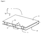
- the figure 1 illustrates a composite panel according to the invention (1).
- Two sheets (21) and (22) are spaced and assembled by profiles (3).
- the sheets are spaced a distance h which corresponds to the height of the profiles in the direction H perpendicular to the plane of the panel.
- the adjacent profiles are substantially parallel to each other in the direction L and spaced apart by an average distance d in the direction D.
- the composite panel comprises three sections defining two distances d between identical profiles.
- the ratio R h / d between on the one hand the distance between the sheets h and on the other hand any of the distances d between adjacent sections is carefully chosen. In fact, if this ratio R is too high, the panel does not locally have the desired mechanical strength and if this ratio is too low, the surface weight of the panel is locally too high. In an advantageous embodiment of the invention, the ratio R is between 0.2 and 1.5 and preferably between 0.4 and 1.0.
- the composite panel is used as a floor, it is advantageous to distinguish the upper sheet (21), in contact with the load transported from the lower sheet (22). Indeed, in this case, it is advantageous that the upper sheet (21) has mechanical characteristics (R 0.2 and R m ) greater than that of the lower sheet (22) and / or a greater thickness.
- the superior mechanical characteristics are obtained in particular by the choice of the alloy and / or the metallurgical state. Given the constraints imposed, which are typically those of a floor capable of supporting motorized vehicles possibly carrying loads, the optimum thickness of the upper sheet is typically between 2 and 4 mm and that of the lower sheet is typically between 1 and 3 mm.
- the thickness of the upper sheet is advantageously greater by at least 30% and preferably by at least 50%, than the thickness of the lower sheet, particularly if the bottom sheet has mechanical characteristics at least equal to those of the upper plate.
- the thickness of the sheet is the thickness outside the thickness of the relief.
- the upper plate is in direct contact with the transported loads and must provide mechanical functions as well as contact functions.
- the function of the lower plate is to reinforce the assembly of the panel and for certain applications to protect the upper plate and the profiles of the outer projections, in particular to prevent their corrosion. In one embodiment of the invention, however, a perforated lower sheet is used to limit the weight of the panel.
- the panel is used as a floor that the upper face of the upper sheet provides a non-slip function.
- an engraved sheet that is to say a sheet on which a pattern has been printed hollow or in relief, on one or both sides.
- the upper face of the upper plate is etched.
- a sheet made non-slip by any other method, including grooving or sanding.
- a relief comprising a plurality of elongated lines, substantially linear or not, is fine.
- Such patterns are known as the standard names in EN1386 "Damier 2", “Damier 5", “Diamond”, “Barley grain”, “Almond”, and other designations such as “Grain de rice “,” Diamonds “,” Pine cone “,” Damier 3 “(derived from Damier 2 with three parallel lines instead of 2),” Damier 4 “(derived from Damier 5 with 4 parallel lines instead of five) . All these descriptions describe succinctly and figuratively the form of the pattern.
- the checkerboard sheets are also called D2, D3, D4, D5, depending on the number of parallel lines that make up the pattern.
- a pattern that is suitable for carrying out the present invention is that described in the French patent. FR 2,747,948 (Pechiney Rhenalu).
- the profiles can be oriented either in the direction parallel to the length of the panel or in the direction perpendicular to the length of the panel.
- the panel when the panel is used as the floor of a rolling vehicle, or steering wheel, such as in particular a truck, a wagon, a cargo plane, a handling means such as a container, the profiles are oriented in the direction perpendicular to the length of the panel, as in the example of the figure 1 , while when the panel is used as a floor (including fixed or temporary bridge, a bridge), floating vehicle, such as including a ship, the profiles are oriented in the direction parallel to the length of the panel.
- the profiles used in the context of the invention are obtained by spinning.
- the profiles (3) used in the context of the invention comprise at least one transverse portion (31) intended to space the sheets and at least two lateral portions (321) and (322) intended to come into contact with the sheets ( 21) and (22).
- at least one transverse portion (31) is inclined from 5 ° to 70 ° and preferably from 5 ° to 60 ° relative to the direction perpendicular to the plane defined by the sheets.
- the end of the side portions in contact with the sheets is rounded, because an end with a sharp angle, typically a right angle, is unfavorable for assembly by gluing.
- the thickness of the profile is not identical in the transverse portion and the lateral portions. In an advantageous embodiment of the invention, the thickness of the profile is higher in the transverse portion than in the lateral portions.
- the profiles consist of at least 5 and preferably 5 segments, referenced b, c, g, j, and k the transverse portions (31) consisting of at least two and preferably two segments (c and j), the upper lateral portion (321) consisting of at least two and preferably two segments (b and k) and the lower lateral portion (322) consisting of at least one segment and preferably a segment (g), the segment g connecting the two transverse portions.
- a segment is a portion of the section of the profile having two ends: either a free end and an end defined by a non-zero junction angle with another segment, or two ends defined by a non-zero junction angle with another segment.
- the profiles consist of at least nine segments and preferably nine segments, referenced a, b, c, d, g, hj, k and l, the transverse portions (31) being constituted by at least two segments and preferably of two segments (c and j), the upper lateral portion (321) being constituted by at least four segments and preferably by four segments (b, d, h and k) located on either side of the transverse segments and the lower side portion (322) consisting of at least three segments and preferably three segments (a, g, 1), the segment g connecting the two transverse portions.
- This embodiment is particularly advantageous when the composite panel is assembled by gluing.
- the segments added with respect to a five-segment geometry make it possible to considerably reduce the stresses within the glue.
- the maximum stress calculated within the glue is at least 30% less and in some cases at least 50% less than a geometry that does not include these additional segments.
- Additional profiles with the same or different geometry as used for the intermediate profiles (3) can be used at the periphery of the panel so as to partially or completely close the space between the sheets.
- the sheets and profiles are made of aluminum alloy.
- the sheets used in the context of the invention are 5XXX alloy, preferably alloy 5052, 5083, 5086 or 5383.
- an alloy sheet 5083, 5086 or 5383 is advantageously used for the upper sheet while an alloy sheet 5052 or 5383 is advantageously used for the lower sheet.
- the metallurgical state of the sheets used is typically a state H.
- the profiles used in the context of the invention are 5XXX alloy typically in an H or 6XXX state typically in the T5 or T6 state, preferably in the T6 state.
- families of different alloys are used on the one hand for the sheets and on the other hand for the profiles.
- the corrosion resistance of the selected alloys is important especially for certain applications (in particular for panels intended for shipbuilding).
- plated sheets are used.
- the underside of the bottom plate is plated.
- Composite panels according to the invention are advantageously used as floor of a rolling vehicle, floor, deck and / or ramp of floating vehicle or floor of flying vehicle.
- the maximum mechanical stresses likely to be exerted on the panel are determined.
- This estimate can be made by a calculation imposed by a regulation or chosen according to a particular use.
- the level of constraint and its method of evaluation is generally imposed by certification bodies that are members of the International Association of Classification Societies (IACS), such as DNV (Det Norske Veritas), Lloyd's Register, ABS (American Bureau of Shipping), Veritas.
- IACS International Association of Classification Societies
- the objective to be achieved is defined in terms of deformation of the panel and / or in terms of maximum level of acceptable local stress.
- the maximum level of acceptable local stress depends on the yield strength of the materials used and the intended conditions of use.
- a safety factor is defined with respect to the elastic limit of the material to take into account, among other things, fatigue strain conditions.
- a yield point and a density are chosen for the sheets and the profiles. These values are determined in a reasonable way according to the most promising materials for the realization of the panel.
- a fourth step the optimal geometry of the composite panel is calculated.
- the objective of this step is to find the panel with the lowest weight possible that resists the constraints determined in the second step.
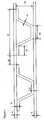
- the composite panel (1) consists of two sheets, an upper plate (21) and a lower plate (22), spaced and assembled by sections (3) divided for the purposes of calculation into 12 sub-segments, referenced by a letter from "a” to "1".
- the transverse portions (31) are constituted by the sub-segments "c” and "j".
- the upper lateral portion (321) which is in contact with the upper plate (21) is constituted by the sub-segments "b", "d", "f", "h” and "k”.
- the lower lateral portion (322) which is in contact with the lower plate (22) is constituted by the sub-segments "a”, “e”, “g”, “i” and "l".
- a sub-segment is a computing unit that can during simulation digital either be deleted or give alone or in combination a segment of the optimized solution.
- a sub-segment differs from a segment in that the angle between sub-segments can be zero (see Fig. 3a , sub-segments d, f and h).
- the upper plate is the sheet in contact with the load.
- the starting geometry used for the profile is advantageous because it allows to reach directly most of the final geometries of possible profiles.
- the calculation advantageously carried out by finite elements, consists of varying the various parameters: thickness of the sheets, length and thickness of each sub-segment of the profiles so as to obtain an optimized solution, that is to say, presenting the best compromise between the weight of the panel, the maximum level of local stresses and / or the deformation of the panel.
- the thickness of the sheets always remains greater than a minimum value of 0.1 mm and preferably 0.5 mm.
- the thickness of the profile sub-segments is either zero (in this case this profile sub-segment is not used) or greater than a minimum value of 0.5 mm and preferably greater than 1 mm.
- the length of the sub-segments of the profile whose thickness is zero may not be equal to zero so as to generate two profiles (see figure 3d ).
- the vertical sub-segments can advantageously be inclined, the angle between the direction perpendicular to the plane defined by the plates (H) and the vertical sub-segments, when they are inclined, being between 5 ° and 70 ° advantageously between 5 ° and 60 ° and preferably between 10 ° and 45 °.
- Three examples of results obtained are given in Figures 3b and 3c (case of a local applied load) and 3d (case of an applied load distributed over the whole surface).
- the geometry obtained for the profile is in the shape of "Omega", the upper lateral portions “b” and “k” being thicker than the lower lateral portion "g".
- the upper plate (21) is thicker than the lower plate (22).
- the figure 3c represents an optimization in which the shear of the glue at the end of the contact zone has been taken into account.
- the geometry obtained for the profile is in the shape of "I".
- the sub-segments "f” and “g” have a zero thickness but their length has increased compared to that of the figure 3a .
- Optimization can also take into account economic requirements such as, for example, the cost of assembling the profiles according to the number of profiles used and the cost of manufacturing the optimized geometries.
- the weight obtained is compared to the objective determined in the first step, if the weight obtained is greater than this objective, we return to the third step.
- a fifth step the cost of the solution obtained is calculated.
- the most suitable metal alloys to reach the elastic limit and density conditions are selected and the cost of obtaining the sheets and profile for these alloys in the optimized geometry is determined.
- the difference between the cost of the solution obtained by making a suitable choice of metallic materials for the optimized geometry and the cost objective determined in the first step is calculated, and if it is positive, it returns to the third step.
- the sheets and profiles are selected alloy selected having the desired geometry.
- a seventh step the panel is assembled.
- the assembly is performed using a method in which there is no metal melting.
- fusion welding methods are not used in the context of the invention. Methods requiring heat treatment of the panel at a temperature above 200 ° C or even above 150 ° C (such as the treatment required to bake an adhesive) are also unfavorable because they generate a loss of mechanical properties.
- the sheets and profiles are assembled by bonding without firing, advantageously using a two-component epoxy type glue, the elements being assembled by pressurization, typically between 50 and 100. kg / m 2 and the panel temperature not exceeding 100 ° C, and advantageously not exceeding the ambient temperature, during the gluing step or later.
- a wire of controlled thickness between the lateral portions of the profiles (321) and (322) and the sheets (21) and (22). It is also possible to introduce calibrated diameter balls into the glue.
- a protrusion of the profile in the direction H on the segments in contact with the sheets (321) and (322) is made so as to control the thickness of glue.
- a surface treatment is performed before assembly by gluing.
- the panels are assembled by friction stir welding.
- FIG. Figure 2 the structure of a composite panel according to the invention optimized for a constraint as described in FIG. Figure 2 .
- a mass of 2 tons (4) of surface 144 cm 2 (length 180 mm, width 80 mm) is applied to the composite panel (1) fixed on two supports (5).
- the length of the panel was 13.8 m and its width 2.3 m.
- the profiles are perpendicular to the direction of the length of the panel.
- the optimization parameters only the thickness of the sheets and the distance between profiles have been optimized.
- the general shape of the profile has not been optimized, the "Omega" form as described in the figure 4 .
- the figure 4 also summarizes the various parameters: thickness of the sheets (e 1 : upper sheet and e 2 : lower sheet), distance between the sections (d), thickness of the different parts of the profile (e 3 thickness of the transverse portion, e 4 : thickness of the upper lateral portion in contact with the upper plate and e 5 : thickness of the lower lateral portion in contact with the lower plate).
- the thicknesses of the different parts of the profile have been fixed.
- a thickness of 2.8 mm was fixed for e 3 and e 5 .
- a thickness of 5 mm was fixed for e 4 .
- the values of d 2 , d 3 , d 4 and d 5 were set at 120 mm, 27 mm, 45 mm and 50 mm, respectively.
- the local constraint is calculated for each element of the grid of the computation and the maximum local stress is thus obtained for each geometry considered. This maximum local stress can then be compared with a target value consistent with the material resistance and the necessary safety factors.
- the figure 5 illustrates the results obtained for different values of d 1 , e 1 and e 2 . In general, it can be seen that the heavier the panels, the lower the maximum local stresses, which reflects the stronger resistance of the panels. Geometries in which the thickness of the upper sheet is higher than that of the lower sheet are the most favorable.
- a panel was made in which the thickness of the upper sheet and that of the lower sheet were 3 mm and the distance between the profiles was 80 mm.
- the upper plate consisted of 5086 alloy in the H244 state while the lower plate consisted of 5383 alloy in the H34 state.
- the profiles consisted of alloy 6005 in the T6 state.
- the sheets and profiles were assembled by gluing using a two-component epoxy type glue. The thickness of the glue was controlled by a piano wire positioned on the parts of the profiles in contact with the sheets, in the area of lower stress. The glue was crosslinked under pressure without heating.
- a sample of the panel obtained with a size of 500 mm by 1300 mm was tested under a force of 30 000 N applied to the center of the sample. No crack was observed, either on the glue, the profiles or the sheets. The maximum displacement observed was 6 mm.
- FIG. Figure 2 the structure of a composite panel according to the invention optimized for a constraint as described in FIG. Figure 2 .
- a load of 0.4 MPa (4) of surface 365 cm 2 (length 215 mm (parallel to the profiles), width 170 mm (perpendicular to the profiles)) is applied to the composite panel (1) fixed on two supports (5).
- panel length was 2.4 m and its width 0.6 m.
- the general shape of the profile has been optimized.
- the "Omega" form as described in FIG. figure 4 .
- the following parameters have been optimized: thickness of the upper and lower plates, distance between the profiles, profile geometry (length and thickness of the different starting sub-segments).
- the local constraint is calculated for each element of the grid of the computation and the maximum local stress is thus obtained for each geometry considered.
- Geometry 2 there is a very clear advantage of Geometry 2 including a reduction of the order of 50% of all the maximum stresses in the glue.
Landscapes
- Engineering & Computer Science (AREA)
- Architecture (AREA)
- Civil Engineering (AREA)
- Structural Engineering (AREA)
- Laminated Bodies (AREA)
- Body Structure For Vehicles (AREA)
Claims (17)
- Metallische Verbundplatte für Konstruktionszwecke, umfassend mindestens zwei im Wesentlichen parallele Bleche (21) und (22) und dazwischen angeordnete Profile (3), welche im Wesentlichen parallel zueinander verlaufen und an den Blechen befestigt sind, wobei jedes Profil einen gleichmäßigen Querschnitt über seine gesamte Länge besitzt, wobei die Profile mindestens einen Querabschnitt (31) aufweisen, der die Bleche (21) und (22) in Abstand voneinander hält, und mindestens zwei Seitenabschnitte (321) und (322) aufweisen, die mit den Blechen in Kontakt kommen, dadurch gekennzeichnet, dass die - mindestens drei - Profile als Abstandsstücke zum Trennen der Bleche dienen und so angeordnet sind, dass der mittlere Abstand zwischen zwei benachbarten Profilen nicht gleichmäßig, sondern den örtlichen Einsatzbedingungen angepasst ist.
- Verbundplatte nach Anspruch 1 zur Verwendung als Boden, bei der das obere Blech (21), welches mit der Last in Kontakt ist, mechanische Eigenschaften und/oder eine Dicke aufweist, die größer ist als die Dicke des unteren Blechs (22), und bei der in bevorzugter Weise die Dicke des oberen Blechs zwischen 2 und 4 mm liegt und die Dicke des unteren Blechs zwischen 1 und 3 mm liegt.
- Verbundplatte nach Anspruch 2, bei der die Oberseite des oberen Blechs (21) Antirutschfunktion hat und vorzugsweise geprägt ist.
- Verbundplatte nach irgendeinem der Ansprüche 1 bis 3, bei der die Profile durch Strangpressen hergestellt sind und das Ende der mit den Blechen in Kontakt kommenden Seitenabschnitte der Profile (321) und (322) abgerundet ist.
- Verbundplatte nach Anspruch 4, bei der mindestens ein Querabschnitt (31) um 5° bis 70° gegenüber einer Richtung senkrecht zu der durch die Bleche definierten Ebene geneigt ist.
- Verbundplatte nach Anspruch 4 oder Anspruch 5, bei der die Dicke der Profile in dem Querabschnitt (31) höher ist als in den Seitenabschnitten (321) und (322).
- Verbundplatte nach irgendeinem der Ansprüche 4 bis 6, bei der die Profile aus mindestens fünf Segmenten bestehen, wobei die Querabschnitte (31) aus mindestens zwei Segmenten bestehen, der obere Seitenabschnitt (321) aus mindestens zwei Segmenten besteht und der untere Seitenabschnitt (322) aus mindestens einem Segment besteht, welches die beiden Querabschnitte verbindet.
- Verbundplatte nach irgendeinem der Ansprüche 4 bis 7, bei der die Profile aus mindestens neun Segmenten bestehen, wobei die Querabschnitte (31) aus mindestens zwei Segmenten bestehen, der obere Seitenabschnitt (321) aus mindestens vier beiderseits der Quersegmente angeordneten Segmenten besteht und der untere Seitenabschnitt (322) aus mindestens drei Segmenten besteht, von denen eins die beiden Querabschnitte verbindet.
- Verbundplatte nach irgendeinem der Ansprüche 1 bis 8, bei der die Bleche und Profile aus einer Aluminiumlegierung bestehen bzw. bei der die Bleche (21) und (22) aus einer Aluminiumlegierung der Serie 5xxx und vorzugsweise aus einer Aluminiumlegierung 5052, 5083, 5086 oder 5383 bestehen und/oder die Profile aus einer Aluminiumlegierung der Serie 5xxx im Zustand H oder einer Aluminiumlegierung der Serie 6xxx im Zustand T6 bestehen.
- Verbundplatte nach irgendeinem der Ansprüche 1 bis 9, bei der die Bleche und Profile durch Klebung, vorzugsweise mit einem Zweikomponenten-Epoxidkleber, ohne Einbrennen unter Druck miteinander verbunden sind, wobei die Temperatur der Platte beim Kleben oder zu einem späteren Zeitpunkt 100 °C nicht übersteigt,.
- Verbundplatte nach irgendeinem der Ansprüche 1 bis 10, bei der die Bleche und Profile durch Reibrührschweißung miteinander verbunden sind.
- Verfahren zur Herstellung einer metallischen Verbundplatte umfassend mindestens zwei im Wesentlichen parallele Bleche und mindestens drei dazwischen angeordnete Profile, welche im Wesentlichen parallel zueinander verlaufen, an den Blechen befestigt sind und als Abstandsstücke zum Trennen der Bleche dienen, wobei jedes Profil einen gleichmäßigen Querschnitt über seine gesamte Länge besitzt, dadurch gekennzeichnet, dass es folgende aufeinanderfolgende Schritte aufweist:(i) Ermitteln der Kosten und des höchstzulässigen Gewichts für die Herstellung der Platte in Abhängigkeit von dem Verwendungszweck der Platte,(ii) Ermitteln der maximalen mechanischen Belastungen, die auf die Platte einwirken können, je nach Verwendungszweck der Platte,(iii) Wählen einer Dehngrenze und Dichte für die Bleche und Profile,(iv) Berechnen der optimalen Geometrie der Platte, insbesondere(a) der Dicke der Bleche,(b) der Geometrie der Profile,(c) des Abstands zwischen den Profilen,
um eine Platte mit möglichst geringem Gewicht zu erhalten, die den in Schritt (ii) bestimmten Belastungen standhält, und wenn das erhaltene Gewicht über dem in Schritt (i) bestimmten Gewicht liegt, Zurückkehren zu Schritt (iii),(v) Berechnen, vorzugsweise durch finite Elemente, der Differenz zwischen den Kosten der durch eine geeignete Wahl der metallischen Werkstoffe im Hinblick auf die optimierte Geometrie in Schritt (iv) erhaltenen Lösung einerseits und den in Schritt (i) bestimmten Kosten andererseits, und wenn die Differenz positiv ist, Zurückgehen zu Schritt (iii),(vi) Bereitstellen der in Schritt (v) gewählten Bleche und Profile,(vii) Verbinden der Bleche und Profile durch Kleben ohne Einbrennen oder durch Reibrührschweißen. - Verfahren nach Anspruch 12, bei dem die Ausgangsgeometrie für die Berechnung eine Verbundplatte (1) ist, welche aus zwei Blechen besteht, einem oberen Blech (21) und einem unteren Blech (22), die voneinander beabstandet und durch in 12 Teilsegmente unterteilte Profile (3) miteinander verbunden sind, wobei die Querabschnitte (31) aus zwei Teilsegmenten bestehen, der obere Seitenabschnitt (321), der mit dem oberen Blech (21) in Kontakt ist, aus 5 Teilsegmenten besteht, der untere Seitenabschnitt (322), der mit dem unteren Blech (22) in Kontakt ist, aus 5 Teilsegmenten besteht, und bei dem die Berechnung darin besteht, die einzelnen Parameter, d.h. Dicke der Bleche, Länge und Dicke jedes Teilsegments der Profile, zu verändern, um eine optimierte Lösung zu erhalten, d.h. die den besten Kompromiss zwischen dem Gewicht der Platte, dem Höchstmaß an örtlichen Belastungen und/oder der Verformung der Platte aufweist.
- Verfahren nach Anspruch 13, bei dem die Dicke der Bleche immer über einem Mindestwert von 0,1 mm und vorzugsweise 0,5 mm bleibt und die Dicke der Profilteilsegmente entweder Null ist oder über einem Mindestwert von 0,5 mm und vorzugweise 1 mm liegt.
- Verfahren nach irgendeinem der Ansprüche 12 bis 14, bei dem die Elemente durch Kleben, vorzugsweise mit einem Zweikomponenten-Epoxidkleber, unter einem Druck im Bereich zwischen 50 und 100 kg/m2 verbunden werden und die Temperatur der Platte beim Kleben oder zu einem späteren Zeitpunkt 100 °C nicht übersteigt.
- Verfahren nach irgendeinem der Ansprüche 12 bis 15, bei dem die Elemente durch Reibrührschweißen verbunden werden.
- Verwendung einer Verbundplatte nach irgendeinem der Ansprüche 1 bis 11 als Boden eines rollenden Fahrzeugs oder als Boden, Deck und/oder Rampe eines schwimmenden Fahrzeugs oder als Boden eines fliegenden Fahrzeugs.
Applications Claiming Priority (3)
| Application Number | Priority Date | Filing Date | Title |
|---|---|---|---|
| FR0700923A FR2912490B1 (fr) | 2007-02-09 | 2007-02-09 | Panneau composite metallique et procede de fabrication |
| US94527107P | 2007-06-20 | 2007-06-20 | |
| PCT/FR2008/000151 WO2008113911A2 (fr) | 2007-02-09 | 2008-02-08 | Panneau composite métallique et procede de fabrication |
Publications (2)
| Publication Number | Publication Date |
|---|---|
| EP2115233A2 EP2115233A2 (de) | 2009-11-11 |
| EP2115233B1 true EP2115233B1 (de) | 2016-07-27 |
Family
ID=38515495
Family Applications (1)
| Application Number | Title | Priority Date | Filing Date |
|---|---|---|---|
| EP08761854.2A Not-in-force EP2115233B1 (de) | 2007-02-09 | 2008-02-08 | Verbundmetalltafel und herstellungsverfahren dafür |
Country Status (5)
| Country | Link |
|---|---|
| US (1) | US8393129B2 (de) |
| EP (1) | EP2115233B1 (de) |
| AU (1) | AU2008228154B2 (de) |
| FR (1) | FR2912490B1 (de) |
| WO (1) | WO2008113911A2 (de) |
Families Citing this family (23)
| Publication number | Priority date | Publication date | Assignee | Title |
|---|---|---|---|---|
| US20140372082A1 (en) * | 2000-12-01 | 2014-12-18 | Aleksandr I. KAMENOMOSTSKIY | Tool for optimized thin wall profile member (tpm) and tpm-panel design and selection |
| US20020184850A1 (en) * | 2002-06-04 | 2002-12-12 | Kamenomostski Alexandre Ilich | Thin-webbed profile member and panel based on it (variants) |
| US8100316B2 (en) * | 2008-05-29 | 2012-01-24 | Airbus Operations Gmbh | Method for joining aircraft fuselage elements by friction stir welding (fsw) |
| US7857191B2 (en) * | 2008-06-16 | 2010-12-28 | Embraer-Empresa Brasileira De Aeronautica S.A. | Friction stir welding (FSW) methods and systems and friction stir welded components made thereby |
| US20100199590A1 (en) * | 2009-02-06 | 2010-08-12 | Aar Corp. | Aircraft Cargo Pallet and Method of Manufacture |
| US9091049B2 (en) | 2010-08-24 | 2015-07-28 | James Walker | Ventilated structural panels and method of construction with ventilated structural panels |
| US8534018B2 (en) * | 2010-08-24 | 2013-09-17 | James Walker | Ventilated structural panels and method of construction with ventilated structural panels |
| US8615945B2 (en) * | 2010-08-24 | 2013-12-31 | James Walker | Ventilated structural panels and method of construction with ventilated structural panels |
| US9604428B2 (en) | 2010-08-24 | 2017-03-28 | James Walker | Ventilated structural panels and method of construction with ventilated structural panels |
| US9050766B2 (en) | 2013-03-01 | 2015-06-09 | James Walker | Variations and methods of producing ventilated structural panels |
| US9740799B2 (en) | 2010-12-03 | 2017-08-22 | The Regents Of The University Of Colorado, A Body Corporate | Cut-fold shape technology for engineered molded fiber boards |
| US9010054B2 (en) * | 2011-06-15 | 2015-04-21 | Biosips, Inc. | Structural insulated building panel |
| CN103075629B (zh) * | 2011-10-26 | 2016-07-20 | 上海卫星工程研究所 | 一种大型预埋复杂小变形框架蜂窝板 |
| CN103071908B (zh) * | 2013-01-18 | 2014-11-12 | 中国人民解放军理工大学野战工程学院 | 一种大面积双层钢板间设置多根加强肋的爆炸焊接方法 |
| DE102013002504A1 (de) * | 2013-02-14 | 2014-08-14 | Daimler Ag | Kraftfahrzeug-Bodenstruktur |
| JP5811168B2 (ja) * | 2013-12-25 | 2015-11-11 | トヨタ自動車株式会社 | 車両用電池搭載構造 |
| SE1551682A1 (en) * | 2015-12-21 | 2017-06-22 | Macgregor Sweden Ab | Load-bearing panel for cargo on a ship |
| WO2017129160A1 (de) * | 2016-01-27 | 2017-08-03 | Bpe E.K. | Schwimmfähige solaranlage und verfahren zu deren betrieb |
| CH712884A1 (de) * | 2016-09-07 | 2018-03-15 | Ludwig Elkuch Ag | Verfahren zur Herstellung eines flächigen Distanzkörpers und Distanzkörper. |
| CN113016101A (zh) * | 2018-11-13 | 2021-06-22 | 瑞维安知识产权控股有限责任公司 | 具有底部防冲击护罩的电动车辆电池组 |
| US11541440B2 (en) | 2019-07-25 | 2023-01-03 | National Research Council Of Canada | Snap-fit extrusions for forming panels |
| CN111222263B (zh) * | 2019-10-31 | 2023-04-07 | 长春英利汽车工业股份有限公司 | 一种仪表板横梁振动试验有限元模拟方法 |
| WO2025237593A1 (de) | 2024-05-14 | 2025-11-20 | Sew-Eurodrive Gmbh & Co Kg | Behältnis zur beurteilung einer vergussmasse |
Family Cites Families (25)
| Publication number | Priority date | Publication date | Assignee | Title |
|---|---|---|---|---|
| US3258892A (en) * | 1962-11-16 | 1966-07-05 | Washington Aluminum Company In | Panel structure |
| FR2207581A5 (en) * | 1972-11-22 | 1974-06-14 | Wendel Sidelor | Hollow steel constructional slab or panel - for building, coach building, etc. formed by glueing constituent parts |
| US4425980A (en) * | 1981-12-14 | 1984-01-17 | The Boeing Company | Beam dampers for damping the vibrations of the skin of reinforced structures |
| GB8808280D0 (en) * | 1988-04-08 | 1988-05-11 | Lk Tool Co Ltd | Machine structure |
| US5128195A (en) * | 1990-03-13 | 1992-07-07 | Hexcel Corporation | Woven core structure |
| US5162143A (en) * | 1990-03-30 | 1992-11-10 | The United States Of America As Represented By The Administrator, National Aeronautics And Space Administration | Core design for use with precision composite reflectors |
| EP0589054A1 (de) * | 1992-03-30 | 1994-03-30 | Nippon Steel Corporation | Platte mit honigwabenstruktur und verfahren zur herstellung derselben |
| US5635306A (en) * | 1992-03-30 | 1997-06-03 | Nippon Steel Corporation | Honeycomb panel and process for producing same |
| FR2691923B1 (fr) * | 1992-06-04 | 1994-09-09 | Europ Propulsion | Structure en nid d'abeilles en matériau composite thermostructural et son procédé de fabrication. |
| US5424113A (en) * | 1993-06-23 | 1995-06-13 | The United States Of America As Represented By The Secretary Of The Navy | Lattice core sandwich construction |
| US5348601A (en) * | 1993-06-23 | 1994-09-20 | The United States Of America As Represented By The Secretary Of The Navy | Method of making an offset corrugated sandwich construction |
| US5543204A (en) * | 1995-01-05 | 1996-08-06 | The United States Of America As Represented By The Secretary Of The Navy | Bi-directionally corrugated sandwich construction |
| CN1322242C (zh) * | 1996-03-19 | 2007-06-20 | 株式会社日立制作所 | 摩擦焊接用结构体 |
| FR2747948B1 (fr) * | 1996-04-29 | 1998-07-03 | Pechiney Rhenalu | Tole metallique gravee a motif repetitif |
| US5894044A (en) * | 1997-04-21 | 1999-04-13 | The Procter & Gamble Company | Honeycomb structure and method of making |
| US5876831A (en) * | 1997-05-13 | 1999-03-02 | Lockheed Martin Corporation | High thermal conductivity plugs for structural panels |
| US6209273B1 (en) * | 1997-05-30 | 2001-04-03 | Steelcase Development Inc. | Panel wall construction |
| AU747689B2 (en) * | 1998-10-30 | 2002-05-16 | Corus Aluminium Walzprodukte Gmbh | Composite aluminium panel |
| US7377084B2 (en) * | 2000-04-24 | 2008-05-27 | Hunter Douglas Inc. | Compressible structural panel |
| FI108340B (fi) * | 2000-10-18 | 2002-01-15 | Pentti Kujala | Metallinen kerroslevyrakenne |
| US7334374B2 (en) * | 2001-08-03 | 2008-02-26 | Schmid Ben L | Stucco sheathing fastener |
| JP3918699B2 (ja) * | 2002-09-20 | 2007-05-23 | ヤマハ株式会社 | 中空パネル |
| DE102004002115B4 (de) * | 2004-01-14 | 2006-08-17 | Ewald Dörken Ag | Noppenbahn, Verbundplatte und Verfahren zur Herstellung einer Noppenbahn |
| US7930861B2 (en) * | 2006-12-04 | 2011-04-26 | Composite Panel Systems Llc | Building, building walls and other structures |
| US7690720B2 (en) * | 2008-01-31 | 2010-04-06 | Gm Global Technology Operations, Inc. | Energy absorbing vehicle hood assembly with asymmetric sandwich inner structure |
-
2007
- 2007-02-09 FR FR0700923A patent/FR2912490B1/fr active Active
-
2008
- 2008-02-08 EP EP08761854.2A patent/EP2115233B1/de not_active Not-in-force
- 2008-02-08 WO PCT/FR2008/000151 patent/WO2008113911A2/fr not_active Ceased
- 2008-02-08 US US12/028,226 patent/US8393129B2/en not_active Expired - Fee Related
- 2008-02-08 AU AU2008228154A patent/AU2008228154B2/en active Active
Also Published As
| Publication number | Publication date |
|---|---|
| WO2008113911A2 (fr) | 2008-09-25 |
| US20080202066A1 (en) | 2008-08-28 |
| WO2008113911A3 (fr) | 2009-07-23 |
| FR2912490A1 (fr) | 2008-08-15 |
| AU2008228154B2 (en) | 2013-11-28 |
| AU2008228154A1 (en) | 2008-09-25 |
| FR2912490B1 (fr) | 2010-10-29 |
| EP2115233A2 (de) | 2009-11-11 |
| US8393129B2 (en) | 2013-03-12 |
Similar Documents
| Publication | Publication Date | Title |
|---|---|---|
| EP2115233A2 (de) | Verbundmetalltafel und herstellungsverfahren dafür | |
| EP2464505B1 (de) | Verfahren zur reparatur einer wand aus mehreren schichten | |
| EP3096998B1 (de) | Vorrichtung für fahrzeugkarosserieaufbau | |
| WO2011110685A1 (fr) | Procede de fabrication d'un assemblage metallique ayant une feuille d'aluminium traitee thermiquement pour obtenir de l'alumine alpha et une autre feuille avec des irregularites de surface que s'y incrustent lors du colaminage. | |
| EP2723558B1 (de) | Kern eines baumaterials, blatt und montageverfahren | |
| EP1571079B1 (de) | Rumpfholm für ein Flugzeug und Flügelmittelkasten mit einem solchen Rumpfholm | |
| EP1787801B1 (de) | Kiste aus einer Verbundplatte | |
| FR2513291A1 (fr) | Poutre de coffrage en bois et procede pour la fabrication d'une poutre de coffrage en bois de ce type | |
| EP2032419B1 (de) | Mittels stumpfverbindung erzeugtes strukturelement für ein kraftfahrzeug | |
| FR2980136A1 (fr) | Composites, leur procede de preparation et les voiles de vol les comprenant | |
| EP2969544A1 (de) | Strukturmaterialkern auf der basis von profilelementen, strukturmaterial und herstellungsverfahren | |
| EP4225518B1 (de) | Blechtafel mit erhöhten bereichen zur erzeugung eines industriefussbodens mit verbesserten hafteigenschaften | |
| FR2552017A1 (fr) | Panneau composite de haute resistance | |
| EP1743986A2 (de) | Hohlkammerplatte | |
| FR2944359A1 (fr) | Procede de fabrication d'un miroir a variation de reflexion d'intensite lumineuse | |
| EP3271233B1 (de) | Anordnung mit flexibler verbindung und flexible verbindung für eine derartige anordnung | |
| EP3328637B1 (de) | Mehrschichtige holzplatte und verfahren zum schneiden und zusammensetzen von kantgrünholz zur herstellung solch einer platte | |
| EP3765284A1 (de) | Geschichtetes aluminium-verbundwerkstoff-hybridbauteil | |
| FR2673222A1 (fr) | Element de revetement boise tel qu'un lambris et procede de fabrication d'un tel element. | |
| EP3516128B1 (de) | Hohles längliches bauelement | |
| FR3051678A1 (fr) | Ski a noyau allege | |
| FR3102401A1 (fr) | Film d’isolation logistique et son procédé de fabrication | |
| FR2989917A1 (fr) | Procede de fabrication d'un modele destine a etre utilise pour la realisation de pieces en materiau composite | |
| FR2948586A1 (fr) | Feuille de materiau bi-matieres et procede de fabrication d'une telle feuille | |
| CA2233764A1 (fr) | Escalier ultra leger |
Legal Events
| Date | Code | Title | Description |
|---|---|---|---|
| PUAI | Public reference made under article 153(3) epc to a published international application that has entered the european phase |
Free format text: ORIGINAL CODE: 0009012 |
|
| 17P | Request for examination filed |
Effective date: 20090717 |
|
| AK | Designated contracting states |
Kind code of ref document: A2 Designated state(s): AT BE BG CH CY CZ DE DK EE ES FI FR GB GR HR HU IE IS IT LI LT LU LV MC MT NL NO PL PT RO SE SI SK TR |
|
| RAP1 | Party data changed (applicant data changed or rights of an application transferred) |
Owner name: CONSTELLIUM FRANCE |
|
| DAX | Request for extension of the european patent (deleted) | ||
| 17Q | First examination report despatched |
Effective date: 20141202 |
|
| REG | Reference to a national code |
Ref country code: DE Ref legal event code: R079 Ref document number: 602008045331 Country of ref document: DE Free format text: PREVIOUS MAIN CLASS: E04C0002340000 Ipc: E04C0002080000 |
|
| RIC1 | Information provided on ipc code assigned before grant |
Ipc: B63B 3/48 20060101ALI20151026BHEP Ipc: E04C 2/08 20060101AFI20151026BHEP Ipc: B63B 29/02 20060101ALI20151026BHEP Ipc: E04C 2/34 20060101ALI20151026BHEP |
|
| GRAP | Despatch of communication of intention to grant a patent |
Free format text: ORIGINAL CODE: EPIDOSNIGR1 |
|
| INTG | Intention to grant announced |
Effective date: 20151221 |
|
| RAP1 | Party data changed (applicant data changed or rights of an application transferred) |
Owner name: CONSTELLIUM ISSOIRE |
|
| GRAS | Grant fee paid |
Free format text: ORIGINAL CODE: EPIDOSNIGR3 |
|
| GRAA | (expected) grant |
Free format text: ORIGINAL CODE: 0009210 |
|
| AK | Designated contracting states |
Kind code of ref document: B1 Designated state(s): AT BE BG CH CY CZ DE DK EE ES FI FR GB GR HR HU IE IS IT LI LT LU LV MC MT NL NO PL PT RO SE SI SK TR |
|
| REG | Reference to a national code |
Ref country code: GB Ref legal event code: FG4D Free format text: NOT ENGLISH |
|
| REG | Reference to a national code |
Ref country code: CH Ref legal event code: EP |
|
| REG | Reference to a national code |
Ref country code: AT Ref legal event code: REF Ref document number: 815925 Country of ref document: AT Kind code of ref document: T Effective date: 20160815 |
|
| REG | Reference to a national code |
Ref country code: IE Ref legal event code: FG4D Free format text: LANGUAGE OF EP DOCUMENT: FRENCH |
|
| REG | Reference to a national code |
Ref country code: DE Ref legal event code: R096 Ref document number: 602008045331 Country of ref document: DE |
|
| REG | Reference to a national code |
Ref country code: NL Ref legal event code: FP |
|
| REG | Reference to a national code |
Ref country code: SE Ref legal event code: TRGR |
|
| REG | Reference to a national code |
Ref country code: NO Ref legal event code: T2 Effective date: 20160727 |
|
| REG | Reference to a national code |
Ref country code: LT Ref legal event code: MG4D |
|
| REG | Reference to a national code |
Ref country code: AT Ref legal event code: MK05 Ref document number: 815925 Country of ref document: AT Kind code of ref document: T Effective date: 20160727 |
|
| PG25 | Lapsed in a contracting state [announced via postgrant information from national office to epo] |
Ref country code: HR Free format text: LAPSE BECAUSE OF FAILURE TO SUBMIT A TRANSLATION OF THE DESCRIPTION OR TO PAY THE FEE WITHIN THE PRESCRIBED TIME-LIMIT Effective date: 20160727 Ref country code: IS Free format text: LAPSE BECAUSE OF FAILURE TO SUBMIT A TRANSLATION OF THE DESCRIPTION OR TO PAY THE FEE WITHIN THE PRESCRIBED TIME-LIMIT Effective date: 20161127 Ref country code: LT Free format text: LAPSE BECAUSE OF FAILURE TO SUBMIT A TRANSLATION OF THE DESCRIPTION OR TO PAY THE FEE WITHIN THE PRESCRIBED TIME-LIMIT Effective date: 20160727 Ref country code: FI Free format text: LAPSE BECAUSE OF FAILURE TO SUBMIT A TRANSLATION OF THE DESCRIPTION OR TO PAY THE FEE WITHIN THE PRESCRIBED TIME-LIMIT Effective date: 20160727 |
|
| REG | Reference to a national code |
Ref country code: FR Ref legal event code: PLFP Year of fee payment: 10 |
|
| PG25 | Lapsed in a contracting state [announced via postgrant information from national office to epo] |
Ref country code: AT Free format text: LAPSE BECAUSE OF FAILURE TO SUBMIT A TRANSLATION OF THE DESCRIPTION OR TO PAY THE FEE WITHIN THE PRESCRIBED TIME-LIMIT Effective date: 20160727 Ref country code: PL Free format text: LAPSE BECAUSE OF FAILURE TO SUBMIT A TRANSLATION OF THE DESCRIPTION OR TO PAY THE FEE WITHIN THE PRESCRIBED TIME-LIMIT Effective date: 20160727 Ref country code: LV Free format text: LAPSE BECAUSE OF FAILURE TO SUBMIT A TRANSLATION OF THE DESCRIPTION OR TO PAY THE FEE WITHIN THE PRESCRIBED TIME-LIMIT Effective date: 20160727 Ref country code: ES Free format text: LAPSE BECAUSE OF FAILURE TO SUBMIT A TRANSLATION OF THE DESCRIPTION OR TO PAY THE FEE WITHIN THE PRESCRIBED TIME-LIMIT Effective date: 20160727 Ref country code: PT Free format text: LAPSE BECAUSE OF FAILURE TO SUBMIT A TRANSLATION OF THE DESCRIPTION OR TO PAY THE FEE WITHIN THE PRESCRIBED TIME-LIMIT Effective date: 20161128 Ref country code: GR Free format text: LAPSE BECAUSE OF FAILURE TO SUBMIT A TRANSLATION OF THE DESCRIPTION OR TO PAY THE FEE WITHIN THE PRESCRIBED TIME-LIMIT Effective date: 20161028 |
|
| PG25 | Lapsed in a contracting state [announced via postgrant information from national office to epo] |
Ref country code: EE Free format text: LAPSE BECAUSE OF FAILURE TO SUBMIT A TRANSLATION OF THE DESCRIPTION OR TO PAY THE FEE WITHIN THE PRESCRIBED TIME-LIMIT Effective date: 20160727 Ref country code: RO Free format text: LAPSE BECAUSE OF FAILURE TO SUBMIT A TRANSLATION OF THE DESCRIPTION OR TO PAY THE FEE WITHIN THE PRESCRIBED TIME-LIMIT Effective date: 20160727 |
|
| REG | Reference to a national code |
Ref country code: DE Ref legal event code: R097 Ref document number: 602008045331 Country of ref document: DE |
|
| PG25 | Lapsed in a contracting state [announced via postgrant information from national office to epo] |
Ref country code: BG Free format text: LAPSE BECAUSE OF FAILURE TO SUBMIT A TRANSLATION OF THE DESCRIPTION OR TO PAY THE FEE WITHIN THE PRESCRIBED TIME-LIMIT Effective date: 20161027 Ref country code: SK Free format text: LAPSE BECAUSE OF FAILURE TO SUBMIT A TRANSLATION OF THE DESCRIPTION OR TO PAY THE FEE WITHIN THE PRESCRIBED TIME-LIMIT Effective date: 20160727 Ref country code: CZ Free format text: LAPSE BECAUSE OF FAILURE TO SUBMIT A TRANSLATION OF THE DESCRIPTION OR TO PAY THE FEE WITHIN THE PRESCRIBED TIME-LIMIT Effective date: 20160727 Ref country code: BE Free format text: LAPSE BECAUSE OF NON-PAYMENT OF DUE FEES Effective date: 20170228 Ref country code: DK Free format text: LAPSE BECAUSE OF FAILURE TO SUBMIT A TRANSLATION OF THE DESCRIPTION OR TO PAY THE FEE WITHIN THE PRESCRIBED TIME-LIMIT Effective date: 20160727 |
|
| PLBE | No opposition filed within time limit |
Free format text: ORIGINAL CODE: 0009261 |
|
| STAA | Information on the status of an ep patent application or granted ep patent |
Free format text: STATUS: NO OPPOSITION FILED WITHIN TIME LIMIT |
|
| 26N | No opposition filed |
Effective date: 20170502 |
|
| PG25 | Lapsed in a contracting state [announced via postgrant information from national office to epo] |
Ref country code: SI Free format text: LAPSE BECAUSE OF FAILURE TO SUBMIT A TRANSLATION OF THE DESCRIPTION OR TO PAY THE FEE WITHIN THE PRESCRIBED TIME-LIMIT Effective date: 20160727 |
|
| PG25 | Lapsed in a contracting state [announced via postgrant information from national office to epo] |
Ref country code: MC Free format text: LAPSE BECAUSE OF FAILURE TO SUBMIT A TRANSLATION OF THE DESCRIPTION OR TO PAY THE FEE WITHIN THE PRESCRIBED TIME-LIMIT Effective date: 20160727 |
|
| REG | Reference to a national code |
Ref country code: CH Ref legal event code: PL |
|
| PG25 | Lapsed in a contracting state [announced via postgrant information from national office to epo] |
Ref country code: CH Free format text: LAPSE BECAUSE OF NON-PAYMENT OF DUE FEES Effective date: 20170228 Ref country code: LI Free format text: LAPSE BECAUSE OF NON-PAYMENT OF DUE FEES Effective date: 20170228 |
|
| REG | Reference to a national code |
Ref country code: IE Ref legal event code: MM4A |
|
| PG25 | Lapsed in a contracting state [announced via postgrant information from national office to epo] |
Ref country code: LU Free format text: LAPSE BECAUSE OF NON-PAYMENT OF DUE FEES Effective date: 20170208 |
|
| REG | Reference to a national code |
Ref country code: BE Ref legal event code: MM Effective date: 20170228 |
|
| REG | Reference to a national code |
Ref country code: FR Ref legal event code: PLFP Year of fee payment: 11 |
|
| PG25 | Lapsed in a contracting state [announced via postgrant information from national office to epo] |
Ref country code: IE Free format text: LAPSE BECAUSE OF NON-PAYMENT OF DUE FEES Effective date: 20170208 |
|
| PG25 | Lapsed in a contracting state [announced via postgrant information from national office to epo] |
Ref country code: MT Free format text: LAPSE BECAUSE OF FAILURE TO SUBMIT A TRANSLATION OF THE DESCRIPTION OR TO PAY THE FEE WITHIN THE PRESCRIBED TIME-LIMIT Effective date: 20160727 |
|
| PG25 | Lapsed in a contracting state [announced via postgrant information from national office to epo] |
Ref country code: HU Free format text: LAPSE BECAUSE OF FAILURE TO SUBMIT A TRANSLATION OF THE DESCRIPTION OR TO PAY THE FEE WITHIN THE PRESCRIBED TIME-LIMIT; INVALID AB INITIO Effective date: 20080208 |
|
| PG25 | Lapsed in a contracting state [announced via postgrant information from national office to epo] |
Ref country code: CY Free format text: LAPSE BECAUSE OF NON-PAYMENT OF DUE FEES Effective date: 20160727 |
|
| PG25 | Lapsed in a contracting state [announced via postgrant information from national office to epo] |
Ref country code: TR Free format text: LAPSE BECAUSE OF FAILURE TO SUBMIT A TRANSLATION OF THE DESCRIPTION OR TO PAY THE FEE WITHIN THE PRESCRIBED TIME-LIMIT Effective date: 20160727 |
|
| PGFP | Annual fee paid to national office [announced via postgrant information from national office to epo] |
Ref country code: NO Payment date: 20200227 Year of fee payment: 13 Ref country code: DE Payment date: 20200227 Year of fee payment: 13 Ref country code: SE Payment date: 20200227 Year of fee payment: 13 Ref country code: GB Payment date: 20200227 Year of fee payment: 13 Ref country code: IT Payment date: 20200220 Year of fee payment: 13 Ref country code: NL Payment date: 20200226 Year of fee payment: 13 |
|
| PGFP | Annual fee paid to national office [announced via postgrant information from national office to epo] |
Ref country code: FR Payment date: 20200225 Year of fee payment: 13 |
|
| REG | Reference to a national code |
Ref country code: DE Ref legal event code: R119 Ref document number: 602008045331 Country of ref document: DE |
|
| REG | Reference to a national code |
Ref country code: NO Ref legal event code: MMEP |
|
| REG | Reference to a national code |
Ref country code: SE Ref legal event code: EUG |
|
| GBPC | Gb: european patent ceased through non-payment of renewal fee |
Effective date: 20210208 |
|
| PG25 | Lapsed in a contracting state [announced via postgrant information from national office to epo] |
Ref country code: NO Free format text: LAPSE BECAUSE OF NON-PAYMENT OF DUE FEES Effective date: 20210228 Ref country code: SE Free format text: LAPSE BECAUSE OF NON-PAYMENT OF DUE FEES Effective date: 20210209 |
|
| REG | Reference to a national code |
Ref country code: NL Ref legal event code: MM Effective date: 20210301 |
|
| PG25 | Lapsed in a contracting state [announced via postgrant information from national office to epo] |
Ref country code: NL Free format text: LAPSE BECAUSE OF NON-PAYMENT OF DUE FEES Effective date: 20210301 |
|
| PG25 | Lapsed in a contracting state [announced via postgrant information from national office to epo] |
Ref country code: DE Free format text: LAPSE BECAUSE OF NON-PAYMENT OF DUE FEES Effective date: 20210901 Ref country code: GB Free format text: LAPSE BECAUSE OF NON-PAYMENT OF DUE FEES Effective date: 20210208 Ref country code: FR Free format text: LAPSE BECAUSE OF NON-PAYMENT OF DUE FEES Effective date: 20210228 |
|
| PG25 | Lapsed in a contracting state [announced via postgrant information from national office to epo] |
Ref country code: IT Free format text: LAPSE BECAUSE OF NON-PAYMENT OF DUE FEES Effective date: 20210208 |
|
| P01 | Opt-out of the competence of the unified patent court (upc) registered |
Effective date: 20230411 |