EP4222304B1 - Schneidvorrichtung und verfahren zum durchtrennen von in textilen bändern gewebten vliesabschnitten aus fäden oder filamenten - Google Patents
Schneidvorrichtung und verfahren zum durchtrennen von in textilen bändern gewebten vliesabschnitten aus fäden oder filamenten Download PDFInfo
- Publication number
- EP4222304B1 EP4222304B1 EP20785711.1A EP20785711A EP4222304B1 EP 4222304 B1 EP4222304 B1 EP 4222304B1 EP 20785711 A EP20785711 A EP 20785711A EP 4222304 B1 EP4222304 B1 EP 4222304B1
- Authority
- EP
- European Patent Office
- Prior art keywords
- ribbon
- woven
- fabric
- filament
- cutting
- Prior art date
- Legal status (The legal status is an assumption and is not a legal conclusion. Google has not performed a legal analysis and makes no representation as to the accuracy of the status listed.)
- Active
Links
Images


Classifications
-
- D—TEXTILES; PAPER
- D06—TREATMENT OF TEXTILES OR THE LIKE; LAUNDERING; FLEXIBLE MATERIALS NOT OTHERWISE PROVIDED FOR
- D06H—MARKING, INSPECTING, SEAMING OR SEVERING TEXTILE MATERIALS
- D06H7/00—Apparatus or processes for cutting, or otherwise severing, specially adapted for the cutting, or otherwise severing, of textile materials
- D06H7/02—Apparatus or processes for cutting, or otherwise severing, specially adapted for the cutting, or otherwise severing, of textile materials transversely
- D06H7/025—Apparatus or processes for cutting, or otherwise severing, specially adapted for the cutting, or otherwise severing, of textile materials transversely in line with an embossed or a raised pattern on the fabric; Cutting pile fabric along a loopless or napless zone, e.g. the plain woven portion of towel cloth
-
- D—TEXTILES; PAPER
- D06—TREATMENT OF TEXTILES OR THE LIKE; LAUNDERING; FLEXIBLE MATERIALS NOT OTHERWISE PROVIDED FOR
- D06H—MARKING, INSPECTING, SEAMING OR SEVERING TEXTILE MATERIALS
- D06H7/00—Apparatus or processes for cutting, or otherwise severing, specially adapted for the cutting, or otherwise severing, of textile materials
-
- D—TEXTILES; PAPER
- D06—TREATMENT OF TEXTILES OR THE LIKE; LAUNDERING; FLEXIBLE MATERIALS NOT OTHERWISE PROVIDED FOR
- D06C—FINISHING, DRESSING, TENTERING OR STRETCHING TEXTILE FABRICS
- D06C13/00—Shearing, clipping or cropping surfaces of textile fabrics; Pile cutting; Trimming seamed edges
- D06C13/06—Removing floats
-
- D—TEXTILES; PAPER
- D06—TREATMENT OF TEXTILES OR THE LIKE; LAUNDERING; FLEXIBLE MATERIALS NOT OTHERWISE PROVIDED FOR
- D06H—MARKING, INSPECTING, SEAMING OR SEVERING TEXTILE MATERIALS
- D06H7/00—Apparatus or processes for cutting, or otherwise severing, specially adapted for the cutting, or otherwise severing, of textile materials
- D06H7/02—Apparatus or processes for cutting, or otherwise severing, specially adapted for the cutting, or otherwise severing, of textile materials transversely
-
- D—TEXTILES; PAPER
- D06—TREATMENT OF TEXTILES OR THE LIKE; LAUNDERING; FLEXIBLE MATERIALS NOT OTHERWISE PROVIDED FOR
- D06H—MARKING, INSPECTING, SEAMING OR SEVERING TEXTILE MATERIALS
- D06H7/00—Apparatus or processes for cutting, or otherwise severing, specially adapted for the cutting, or otherwise severing, of textile materials
- D06H7/14—Cutting fabrics by cutting the weft or warp threads while making special provision to avoid cutting warp or weft threads, respectively, adjacent to the cut
Definitions
- the invention relates to a cutting device for severing non-woven-in sections of threads or filaments woven in textile ribbons.
- the invention is furthermore concerned with methods for severing non-woven-in sections of threads or filaments woven in textile ribbons.
- radio-frequency identification enables the producers and retailers to digitally process and/or keep track of the textile goods.
- Tiny antenna filaments woven in the labels are able to communicate why a radiofrequency.
- the labels including the antenna filament are stored as a quasi-endlessly textile ribbon rolled around our band reel.
- each label is cut from the quasi-endless textile ribbon with the quasi-endless antenna filament woven therein before integrated into the clothes.
- a loose end of the antenna filament is thereby generated at each label which may negatively impact the sensitive RFID functionality.
- No solution is present in the prior art, that provides a sufficient severing of the labels and the antenna filament from the quasi-endlessly textile ribbon.
- the document WO 2005/071605 A2 discloses for example a textile material that comprises a high-frequency transponder which includes a circuit module and the antenna linked therewith and set to a working frequency.
- the document DE 10 2011 106 648 A1 discloses a portable data device which consists of an apparatus for storing and processing data, and an antenna for transmitting energy and data, which is connected to the apparatus.
- the document WO2017/216817 discloses a shearing machine on warp and weft, particularly suited to cut bridge threads both vertically and horizontally on any type of fabric.
- the shearing machine comprises at least a first cutting unit and a second cutting unit, spaced apart along a sliding direction of the fabric.
- aspects of the invention may provide solutions for severing non-woven-in sections of metallized threads or filaments, that are alternately woven/non-woven in the fabric of quasi-endlessly textile ribbons.
- the invention is set out in the accompanying set of claims.
- a cutting device for severing non-woven-in sections of threads or filaments woven in textile ribbons comprises: a ribbon conveying table configured to convey a textile ribbon having a metallized thread or filament quasi-endlessly woven/non-woven in the fabric of the ribbon; a ribbon conveying drive configured to convey the ribbon in a conveying direction; at least two cutting assemblies spaced apart from one another along the conveying direction of the textile ribbon, the at least two cutting assemblies being configured to simultaneously perform a cutting action for severing a non-woven-in section of the metallized thread or filament from the fabric of the ribbon; and at least two sliding spacers spaced apart from one another along the conveying direction of the textile ribbon, the at least two sliding spacers each being connected to a respective one of the at least two cutting assemblies, contacting the surface of the ribbon and being configured to slidingly move between the metallized thread or filament and the fabric of the ribbon at the edges of the non-woven-in sections to facilitate the cutting action of the at least
- a cutting device for severing non-woven-in sections of fibers woven in fabric straps comprises: a strap conveying table configured to convey a fabric strap with an electrical conductive fiber quasi-endlessly woven/non-woven in the fabric strap; and at least two tool holding structures each having a scissor assembly and a fiber separator, wherein the tool holding structures are movably connected to the strap conveying table; wherein the scissor assemblies of the at least two tool holding structures are arranged parallel to the conveying direction of the fabric strap and configured to simultaneously perform a severing action for severing a non-woven-in section of the electrical conductive fiber from the fabric strap; wherein the fiber separators are configured to slidingly separate the electrical conductive fiber from the fabric strap at the edges of the non-woven-in sections to facilitate the severing action of the scissor assemblies.
- a method for severing non-woven-in sections of fibers woven in fabric straps comprises the steps of: providing a cutting device, in particular a cutting device of claim 1, and a fabric strap with an electrical conductive fiber quasi-endlessly woven/non-woven in the fabric strap; conveying the fabric strap in the strap conveying table in a conveying direction; stopping the fabric strap after conveying the fabric strap a calculated amount of travel; traveling the tool holding structures from a first position to a second position, wherein the fiber separators slide between the electrical conductive fiber and the fabric strap at the edges of the non-woven-in section causing the electrical conductive fiber to separate from the fabric strap; and simultaneously performing a severing action for severing a non-woven-in section of the electrical conductive fiber from the fabric strap at the edges of the non-woven-in section.
- a fundamental concept of the invention is to simultaneously cut a metallized thread or filament, such as an antenna filament, at the edges of a non-woven-in section of the metallized thread or filament. Since the ribbon is usually fabricated quasi-endlessly the metallized thread or filament is woven/non-woven in the ribbon as well and contacts the fabric of the ribbon, which is conveyed in the ribbon conveying table in the conveying direction, in the non-woven-in section. Therefore, the metallized thread or filament needs to be separated from the fabric in order to perform the cutting action, because the fabric of the ribbon should not be contacted or even damaged by the cutting assemblies.
- the separation of the metallized thread or filament from the fabric of the ribbon in the non-woven-in section is achieved by sliding spacers that slide between the metallized thread or filament and the fabric and thereby separate them the further the more the sliding spacers slide under the metallized thread or filament.
- the metallized thread or filament is fixed to the ribbon, wherein the sliding spacers slide under the metallized thread or filament anywhere between the edges, preferably close to the edges.
- a particular advantage in the solution according to an aspect of the invention is that the non-woven-in section of the metallized thread or filament is severed from the ribbon only leaving a very short loose end of the metallized thread or filament behind at the edge of the woven section.
- the metallized thread or filament remaining in the fabric in the woven section is to communicate via radio frequency, it is very important to not leave a long loose end behind since an undefined loose end of the metallized thread or filament disturbs the radio frequency signal.
- the sliding spacers have a distal end portion, which contacts the fabric when conveying the textile ribbon, and an elongated body extending from the distal end portion in a direction that is basically perpendicular to the conveying direction of the ribbon.
- the elongated body includes an upper surface, which faces away from the fabric and extends from the fabric in an angle between 10° to 80°, preferably between 35° to 55° with regard to a conveying plane of the ribbon conveying table.
- the sliding spacers are positioned closer to each other than the cutting assemblies are positioned to each other.
- the cutting assemblies and/or the sliding spacers are kinematically connected via a tool connecting assembly, in particular a spindle or a shaft, such that the position of and/or the distance between the cutting assemblies and/or the sliding spacers are adjustable in an axis parallel to the conveying direction of the ribbon.
- the cutting assemblies and the sliding spacers have a first position, in which the ribbon is conveyable in the conveying direction, and a second position, wherein in the second position the metallized thread or filament is lifted away from the fabric by the sliding spacers, positioned between the metallized thread or filament and the fabric.
- a travel from the first position to the second position of the cutting assemblies is substantially linear transverse to the conveying direction of the ribbon.
- the cutting device further comprising a travel drive, in particular a pneumatic, hydraulic or electromechanical cylinder, which is coupled to the cutting assemblies and to the sliding spacers and configured to drive at least one of or each of the cutting assemblies and the sliding spacers along the travel by oscillating motion.
- a travel drive in particular a pneumatic, hydraulic or electromechanical cylinder
- the cutting device further comprising a sensor, in particular a capacitive, inductive, magnetic field or optical sensor, configured to sense reference positions of the metallized thread or filament in the fabric and a ribbon conveying drive configured to convey the ribbon in the conveying direction by an amount of travel which is based on the sensed reference positions of the metallized thread or filament in the fabric and a predetermined length of the woven/non-woven sections of the metallized thread or filament in the fabric.
- a sensor in particular a capacitive, inductive, magnetic field or optical sensor
- the cutting device further comprising at least two textile ribbon reels configured to take up the textile ribbon, wherein at least one of the at least two textile ribbon reels is positioned before and at least one of the at least two textile ribbon reels is positioned after the cutting assemblies and the sliding spacers in relation to the conveying direction of the ribbon.
- the cutting device further comprising a quality assurance device for assuring non-woven-in sections of the metallized thread or filament being completely severed from the fabric strap, the quality assurance device being positioned downstream the cutting assemblies and the sliding spacers in relation to the conveying direction of the ribbon.
- the cutting assemblies are configured as scissors each having a fixed scissor blade and a movable scissor blade, wherein the movable scissor blades are coupled to an actuator, in particular a pneumatic, hydraulic or electromechanical cylinder.
- the cutting device further comprising a supporting structure configured to mechanically support the cutting assemblies and the sliding spacers and mounted to the ribbon conveying table, preferably being pivotally mounted to the ribbon conveying table about an axis parallel to the conveying direction of the ribbon.
- the cutting assemblies and the sliding spacers are in a first position, in which a distal end portion of the sliding spacers contacts the fabric.
- the calculated amount of travel is based on a reference position of the metallized thread or filament in the fabric sensed by a sensor, in particular a capacitive, inductive, magnetic field or optical sensor, and a predetermined length of the woven/non-woven sections of the metallized thread or filament in the fabric.
- the sliding spacers with its distal end portion contacting the fabric slide basically linear transverse to the conveying direction of the stopped ribbon, wherein the non-woven section of the metallized thread or filament is lifted along an upper surface of the sliding spacers, wherein the upper surface faces away from the fabric and extends from the fabric in an angle between 10° to 80°, preferably between 35° to 55° with regard to a conveying plane of the ribbon conveying table.
- the method further comprising the step of adjusting the position of and/or the distance between the cutting assemblies and/or the sliding spacers to a length of the non-woven section of the metallized thread or filament in the fabric via a tool connecting assembly, in particular a spindle or a shaft, in an axis parallel to the conveying direction of the ribbon.
- the method further comprising the step of removing the severed metallized thread or filament from the ribbon conveying table where the cutting action is performed by an air stream generated by an air stream generator and streaming over the ribbon conveying table.
- the fiber separators have a distal end portion, which is oriented and configured to contact the fabric strap, and an elongated body extending from the distal end portion in a direction that is basically perpendicular to the conveying direction of the fabric strap.
- the elongated body includes an upper surface, which faces away from the fabric strap and extends from the fabric strap in an angle between 10° to 80°, preferably between 35° to 55° with regard to the strap conveying table.
- the scissor assemblies and the fiber separators of two of the at least two tool holding structures are arranged in the respective tool holding structure such that the fiber separators are closer to each other than the scissor assemblies are to each other.
- the tool holding structures are kinematically connected via a tool connection assembly, in particular a spindle or a shaft, such that the position of and/or the distance between the tool holding structures are adjustable in an axis parallel to the conveying direction of the fabric strap.
- the tool holding structures have a first position, in which the fabric strap is conveyable in the conveying direction, and a second position, wherein in the second position the electrical conductive fiber is separated from the fabric strap by the fiber separators, positioned between the electrical conductive fiber and the fabric strap.
- a travel from the first position to the second position of the tool holding structures is substantially linear transverse to the conveying direction of the fabric strap.
- the device further comprises a travel drive, in particular a pneumatic, hydraulic or electromechanical cylinder, which is coupled to the tool holding structures and configured to drive at least one of or each of the tool holding structures along the travel by oscillating motion.
- a travel drive in particular a pneumatic, hydraulic or electromechanical cylinder, which is coupled to the tool holding structures and configured to drive at least one of or each of the tool holding structures along the travel by oscillating motion.
- the device further comprises a sensor, in particular a capacitive, inductive, magnetic field or optical sensor, configured to sense reference positions of the electrical conductive fiber in the fabric strap and a strap conveying drive configured to convey the fabric strap in the conveying direction by an amount of travel which is based on the sensed reference positions of the electrical conductive fiber in the fabric strap and a predetermined length of the woven/non-woven sections of the electrical conductive fiber.
- a sensor in particular a capacitive, inductive, magnetic field or optical sensor, configured to sense reference positions of the electrical conductive fiber in the fabric strap and a strap conveying drive configured to convey the fabric strap in the conveying direction by an amount of travel which is based on the sensed reference positions of the electrical conductive fiber in the fabric strap and a predetermined length of the woven/non-woven sections of the electrical conductive fiber.
- the device further comprises at least two fabric strap reels configured to take up the fabric strap, wherein at least one of the at least two fabric strap reels is positioned before and at least one of the at least two fabric strap reels is positioned after the at least two tool holding structures in relation to the conveying direction of the fabric strap.
- the device further comprises a quality assurance device for assuring non-woven-in sections of the metallized thread or filament being completely severed from the fabric strap, the quality assurance device being positioned downstream the tool holding structures in relation to the conveying direction of the fabric strap.
- the scissor assemblies are configured as scissors each having a fixed scissor blade and a movable scissor blade, wherein the movable scissor blades are coupled to an actuator, in particular a pneumatic, hydraulic or electromechanical cylinder.
- the tool holding structures are configured to be pivotally in relation to the strap conveying table about an axis parallel to the conveying direction of the fabric strap.
- the tool holding structures are in a first position, in which a distal end portion of the fiber separator contacts the fabric strap.
- the calculated amount of travel is based on a reference position of the thread in the fabric strap sensed by a sensor, in particular a capacitive, inductive, magnetic field or optical sensor, and a predetermined length of the woven/non-woven sections of the electrical conductive fiber in the fabric strap.
- the fiber separators in the step of traveling the fiber separators with its distal end contacting the textile slide basically linear transverse to the conveying direction of the stopped fabric strap, wherein the non-woven section of the electrical conductive fiber is lifted along an upper surface of the fiber separators, wherein the upper surface faces away from the fabric strap and extends from the fabric strap in an angle between 10° to 80°, preferably between 35° to 55° with regard to the strap conveying table.
- the method further comprises the step of adjusting the position of and/or the distance between the tool holding structures to a length of the non-woven section of the electrical conductive fiber in the fabric strap via a tool connecting assembly, in particular a spindle or a shaft, in an axis parallel to the conveying direction of the fabric strap.
- a tool connecting assembly in particular a spindle or a shaft
- the method further comprises the step of removing the severed electrical conductive fiber from the strap conveying table where the severing action is performed by an air stream generated by an air stream generator and streaming over the strap conveying table.
- a ribbon conveying table may also be a strap conveying table in the meaning of the present invention.
- a cutting assembly may also be a scissor assembly in the meaning of the present invention.
- a sliding spacer may also be a fiber separator in the meaning of the present invention.
- a textile ribbon may also be a fabric strap or any textile that is at least double in length in relation to its width in the meaning of the present invention.
- a metallized thread or filament may also be an electrical conductive fiber or any yarn, thread or filament that is able to communicate via radio frequency in the meaning of the present invention.
- a supporting structure may also be a tool holding structure or any structure that is configured to have at least a cutting assembly and a sliding spacer in the meaning of the present invention.
- a ribbon conveying drive may also be strap conveying drive in the meaning of the present invention.
- Fig. 1 and Fig. 2 show a schematic illustration of a textile ribbon 4 with a metallized thread or filament 5 quasi-endlessly woven/non-woven in the fabric of the ribbon 4.
- the textile ribbon 4 is produced quasi-endlessly. Also the metallized thread or filament 5 is produced and woven quasi-endlessly in the fabric of the ribbon 4 such that the metallized thread or filament 5 is an antenna or at least has the properties and functionalities of an antenna.
- Fig. 2 shows a textile ribbon 4 with severed non-woven-in sections 52 of the metallized thread or filament 5.
- the non-woven-in sections 52 are cut at their edges 50, where the woven sections 51 of the metallized thread or filament 5 start/end.
- the woven sections 51 the metallized thread or filament 5 are woven in any pattern, preferably in serpentines, in the textile ribbon 4.
- the metallized thread or filament 5 is woven in the textile ribbon 4 such that the non-woven-in sections 52 and the woven sections 51 alternate in a predetermined length L along the quasi-endlessly ribbon 4, wherein the predetermined length L is the length between an edge 50 of the beginning non-woven-in section 52 and an edge 50 of an ending woven section 51 in a longitudinal direction of the quasi-endlessly ribbon 4 as defined in Fig. 2 .
- the predetermined length L includes the length of the woven section 51 and the non-woven-in section 52 in the longitudinal direction of the quasi-endlessly ribbon 4, the predetermined length L being constant at the textile ribbon 4 according to this embodiment.
- a cutting device 100 according to embodiments of the invention is illustrated schematically. Components and features of the cutting device 100 that are the same in Fig. 3 to 5 are only described once with regard to one of these Figures. Unless described otherwise, these components and features may be included and combined in each embodiment of the invention.
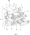
- Fig. 3 shows an isometric illustration of a cutting device 100 for severing non-woven-in sections 52 of threads or filaments 5 woven in textile ribbons 4 according to one embodiment of the invention.
- the cutting device 100 comprises a ribbon conveying table 1, at least two cutting assemblies 2 and at least two sliding spacers 3.
- the ribbon conveying table 1 is configured to convey a textile ribbon 4 having a metallized thread or filament 5 quasi-endlessly woven/non-woven in the fabric of the ribbon 4, in particular the ribbon 4 of Fig. 1 and 2 .
- the ribbon conveying table 1 may have a ribbon conveying drive configured to convey the ribbon 4 in the conveying direction A.
- the ribbon conveying drive may be configured as an electrical, fluidical or combustion engine driving the ribbon 4 by rotating or linear drive means, in particular configured as a conveyor belt system with a plane belt driven between at least two cylindrical rolls.
- the ribbon conveying table 1 may have a basis standing on a floor and supporting at least some of the components of the ribbon conveying table 1.
- the at least two cutting assemblies 2 are spaced apart from one another along the conveying direction A of the textile ribbon 4, the at least two cutting assemblies 2 being configured to simultaneously perform a cutting action for severing a non-woven-in section 52 of the metallized thread or filament 5 from the fabric of the ribbon 4.
- the cutting assemblies 2 are kinematically connected via a tool connecting assembly 10, in particular a spindle or a shaft, such that the position of and/or the distance between the cutting assemblies 2 are adjustable in an axis parallel to the conveying direction A of the ribbon 4.
- the tool connecting assembly 10 is able to manually or automatically adjust the distance between the cutting assemblies 2 to the edges 50 of the metallized thread or filament 5, where the cutting assemblies 2 are to cut the metallized thread or filament 5.
- the tool connecting assembly 10 is configured to manually or automatically change the position of the cutting assemblies 2 in an axis parallel to the conveying direction A of the ribbon 4. Therefore, the embodiment according to Fig. 3 shows a divided threaded spindle, wherein each divisional part of the threaded spindle guides one of the at least two cutting assemblies 2 and wherein the threads of the two divisional parts of the threaded spindle are arranged in opposite direction such that by rotating the spindle the cutting assemblies 2 move closer together or remove from each other in the conveying direction A.
- the spindle might be movably and fixedly supported in a shaft bearing, for example, that allows the spindle to be moved in its longitudinal direction in the conveying direction A.
- the at least two sliding spacers 3 are spaced apart from one another along the conveying direction A of the textile ribbon 4, the at least two sliding spacers 3 each being connected to a respective one of the at least two cutting assemblies 2, contacting the surface of the ribbon 4 and being configured to slidingly move between the metallized thread or filament 5 and the fabric of the ribbon 4 at the edges 50 of the non-woven-in sections 52 to facilitate the cutting action of the at least two cutting assemblies 2.
- the sliding spacers 3 can be kinematically connected via the tool connecting assembly 10, in particular a spindle or a shaft, such that the position of and/or the distance between the sliding spacers 3 are adjustable in an axis parallel to the conveying direction A of the ribbon 4.
- Optional sliding spacers 3 can be kinematically connected via a second tool connecting assembly being kinematically independent from the tool connecting assembly 10, which might connect the cutting assemblies 2.
- the cutting device 100 further comprises support structures 11 in which the cutting assemblies 2 and the sliding spacers 3 are supported, wherein each support structure 11 supports one cutting assembly of the at least two cutting assemblies 2 and one sliding spacer of the at least two sliding spacers 3.
- the support structures 11 can be directly or indirectly connected to the tool connecting assembly 10.
- the cutting device 100 may further comprise a sensor 7 configured to sense reference positions of the metallized thread or filament 5 in the fabric.
- the sensor 7 is in particular configured as a capacitive, inductive, magnetic field or optical sensor.
- the sensor 7 is preferably located upstream the cutting assemblies 2 and the sliding spacers 3 in relation to the conveying direction A of the ribbon 4.
- the sensor 7 might be designed to sense a specific point in the structure of the metallized thread or filament 5.
- the specific point in the structure of the metallized thread or filament 5 could be a starting point to calculate an amount of travel that is needed to travel the textile ribbon 4 in the conveying direction A until the ribbon 4 is stopped in a position relative to the cutting assemblies 2 and the sliding spacers 3 in the conveying direction A, in which the non-woven-in section 52 can be severed from the fabric of the ribbon 4.
- the cutting device 100 may comprise a ribbon conveying drive configured to convey the ribbon 4 in the conveying direction A by the amount of travel which is based on the sensed reference positions of the metallized thread or filament 5 in the fabric and the predetermined length L of the woven/non-woven sections of the metallized thread or filament 5 in the fabric of the ribbon 4.
- the predetermined length L can be defined as described in the embodiment of fig. 2 , as the length of the non-woven-in section 52, as the length of the woven section 51 only or any other length that is characteristic for the textile ribbon 4 to position the edges 50 of the sections 51, 52 of the metallized thread or filament 5 in the above-described relation to the cutting assemblies 2 and the sliding spacers 3 in the conveying direction A.
- the cutting device 100 may further comprise at least two textile ribbon reels 8 configured to take up the textile ribbon 4, wherein at least one of the at least two textile ribbon reels 8 is positioned before and at least one of the at least two textile ribbon reels 8 is positioned after the cutting assemblies 2 and the sliding spacers 3 in relation to the conveying direction A of the ribbon 4.
- the textile ribbon reels 8 can be configured as cardboard sleeves, spools or cylinder like forms. They might be pivotally mounted to the ribbon conveying table 1, wherein the rotation axis of the ribbon reels 8 is perpendicular to the conveying direction A.
- the cutting device 100 may comprise a quality assurance device 9 for assuring non-woven-in sections 52 of the metallized thread or filament 5 being completely severed from the fabric, the quality assurance device 9 being positioned downstream the cutting assemblies 2 and the sliding spacers 3 in relation to the conveying direction A of the ribbon 4.
- the quality assurance device 9 can be configured to visually supervise the surface of the textile ribbon 4 for defects of the ribbon 4 after the cutting action. Defects could be that the nonwoven in section 52 of the metallized thread or filament 5 has not been severed from the ribbon 4 and is still attached to the ribbon 4 or that the woven section 51 of the metallized thread or filament 5 is incorrect.
- the cutting device 100 may have an air stream generator 12 configured to generate an air stream streaming over the ribbon conveying table 1. Therefore, the air stream generator 12 can be figured as an extraction system, as illustrated in Fig. 3 , and arranged next to the ribbon conveying table 1 in view of the conveying direction A and opposite to the cutting assemblies 2 and the sliding spacers 3 with regard to the textile ribbon 4.
- Fig. 4 shows a top view of a cutting device 100 of Fig. 3 according to a further embodiment of the invention.
- the sliding spacers 3 might be positioned closer to each other than the cutting assemblies 2 might be positioned to each other.
- the distance in the conveying direction A between the two illustrated cutting assemblies 2 has a maximum amount being the length of the non-woven-in section 52.
- the cutting assemblies 2 and the sliding spacers 3 can be arranged parallel to each other and transverse to the conveying direction A of the ribbon 4.
- the cutting assemblies 2 and the sliding spacers 3 might have a first position, in which the ribbon 4 is conveyable in the conveying direction A.
- the sliding spacers 3 contact the fabric of the ribbon 4 in a line of the ribbon 4 that is lateral displaced, in particular about 2 mm displaced, from the metallized thread or filament 5, which alignment basically corresponds to the conveying direction A in the non-woven-in section 52, with regard to the conveying direction A.
- the cutting assemblies 2 and the sliding spacers 3 might further have a second position, in which the cutting action is performed by the cutting assemblies 2.
- the sliding spacers 3 can contact the fabric of the ribbon 4 also in the second position, but are not limited thereto and can be positioned lateral to the ribbon 4 not contacting the fabric of the ribbon 4 as well.
- the ribbon 4 is stopped and the sliding spacers 3 are positioned between the metallized thread or filament 5 in the non-woven-in section 52 and the fabric of the ribbon 4, wherein the metallized thread or filament is displaced vertical from the ribbon 4 such that to be cut by the cutting assemblies 2 without the cutting assemblies 2 contacting the fabric of the ribbon 4.
- the cutting device 100 may have a travel drive 6, in particular a pneumatic, hydraulic or electromechanical cylinder, which is coupled to the cutting assemblies 2 and configured to drive at least one of or each of the cutting assemblies 2 along the travel by oscillating motion.
- the travel drive 6 can be coupled to the sliding spacers 3 and configured to drive at least one of or each of the sliding spacers 3 along the travel by oscillating motion.
- a plurality of travel drives 6 can be provided to travel each or groups of the cutting assemblies 2 and on the sliding spacers 3 kinematically and/or timely independently from one another.
- the cutting device 100 might further comprise pins 13, which are configured to guide the ribbon 4 on the ribbon conveying table 1.the plurality of pins 13, shown in fig. 4 , are detachably connected to the ribbon conveying table 1, wherein the pins 13 are configured to be inserted into respective slots positioned in series along the conveying direction A.
- the pins 13 are inserted in those slots being upstream and/or downstream of the cutting assemblies 2 and the sliding spacers 3 in the conveying direction a such that the cutting assemblies 2 and the sliding spacers 3 cannot collide with the pins 13 when the second position of the cutting assemblies 2 and the sliding spacers 3 cause them to be positioned besides the ribbon 4.
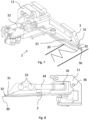
- Fig. 5 shows a side view of a cutting device 100 of Fig. 3 viewed in a conveying direction A of the textile ribbon 4 according to a further embodiment of the invention.
- the travel drive 6 might also be coupled to the supporting structure 11 for traveling the supporting structures 11 supporting the cutting assemblies 2 and the sliding spacers 3 between the first position and the second position.
- the air stream generator 12 is configured as a nozzle arranged above the cutting assemblies 2 and the sliding spacers 3, wherein the head of the nozzle 12 is designed and oriented to generate an airflow streaming over the ribbon conveying table 1 to blow away the section of the metallized thread or filament 5 severed in the cutting action.
- the supporting structure 11 can be configured to mechanically support the cutting assemblies 2 and the sliding spacers 3 and mounted to the ribbon conveying table 1, preferably being pivotally mounted to the ribbon conveying table 1 about an axis W parallel to the conveying direction A of the ribbon 4.
- the supporting structures 11 can be arranged in an arrangement, for example, in a section of the ribbon conveying table 1 such that this section is pivotal to the basis of the ribbon conveying table 1 about the pivot axis W.
- the pivot axis W may be designed as a pivotal joint pivotally connecting the section of the ribbon conveying table 1, which includes at least the supporting structures 11 with the cutting assemblies 2 and the sliding spacers 3 and the travel drive 6, and the basis of the ribbon conveying table 1.
- Pivoting the cutting assemblies 2 and the sliding spacers 3 about the pivot axis W is beneficial for applying the textile ribbon 4 since the cutting assemblies and the sliding spacers 3 are lifted from a conveying plane of the ribbon conveying table 1. Furthermore, operations, such as maintenance or reparation, at the cutting assemblies 2 or the sliding spacers 3 are easier to perform when the cutting assemblies 2 and the sliding spacers 3 are in an upright position.
- Fig. 6 shows a detail extract of the arrangement of cutting assemblies 2 and sliding spacers 3 on a section of the ribbon conveying table 1 with regard to Fig. 5 according to a further embodiment of the invention.
- the arrangement may comprise a travel drive 6, a tool connecting assembly 10, two supporting structures 11 each having a cutting assembly 2 and a sliding spacer 3, a connecting bar 14, first and second guide rails 15, 16 and sliding bodies 17.
- the first guide rail 16 and the tool connecting assembly 10, in particular a divided spindle, are arranged parallel to one other and connected to a plate which might be pivotally mounted to the basis of the ribbon conveying table 1 about the people axis W.
- the sliding bodies 17 are connected to the tool connecting assembly 10 and guided in the first guide rail 16.
- the second guide rail 15 is provided and arranged perpendicular to the tool connecting assembly 10 and the first guide rail 16. With the second guide rail 15 the supporting structure 11 is guided.
- the two supporting structures 11 are slidingly connected via the connecting bar 14, the connecting bar 14 being parallel to the tool connecting assembly 10 and the first guide rail 16.
- the connecting bar 14 is configured to allow sliding of the two supporting structures 11 along the first guide rail 16, wherein the two supporting structures 11 are driven by the tool connecting assembly 10.
- the travel drive 6 drives the supporting structures 11 along the second guide rails 15, wherein the travel drive 6 might further be fixed to the plate or a housing of the section of the ribbon conveying table.
- the first and the second guide rails 15, 16 can be configured as carriage guidance systems, for example, made of metals, light metals, plastics or combinations thereof.
- Fig. 7 and Fig. 8 show a schematic illustration of a supporting structure 11 having a cutting assembly 2 and a sliding spacer 3 according to a further embodiment of the invention.
- the sliding spacer 3 may have a distal end portion 30, which contacts the fabric when conveying the textile ribbon 4.
- the edges of the sliding spacer 3, in particular the distal end portion 30, can provide a radius lower than 1 mm.
- the sliding spacers 3 may further have an elongated body 31 extending from the distal end portion 30 in a direction that is basically perpendicular to the conveying direction A of the ribbon 4.
- the elongated body 31 includes an upper surface 32, which faces away from the fabric and extends from the fabric in an angle between 10° to 80°, preferably between 35° to 55° with regard to a conveying plane of the ribbon conveying table 1.
- the distal end portion 30 and the elongated body 31 can be made of metal, light metal, plastics or combinations thereof. Additionally the distal end portion 30 and the elongated body 31 can be configured elastically.
- the cutting assembly 2 can be configured as a scissor having a fixed scissor blade 20 and a movable scissor blade 21, wherein the movable scissor blade 21 is coupled to an actuator 22, in particular a pneumatic, hydraulic or electromechanical cylinder.
- the actuator 22 is supported by the supporting structure 11.
- the scissor blades 20, 21 might be arranged at 0.2-0.5 mm above the textile ribbon 4 when conveyed in the ribbon conveying table 1. Moreover, the scissor blades 20, 21 can be arranged parallel to the textile ribbon 4.
- the scissor blades 20, 21 can also be arranged in an angle, in particular 0 to 45°, about the longitudinal axis of the scissor relative to the textile ribbon 4 such that it is easier for the cutting assembly 2 to cut the lifted metallized thread or filament 5 when the lifted metallized thread or filament 5 extending basically diagonal in relation to the conveying plane of the ribbon conveying table 1.
- the fixed scissor blade 20 lies below the movable scissor blade 21, but is not limited to that configuration and can also lie above the movable scissor blade 21.
- the movable scissor blade 21 may be closer to the sliding spacer 3 in an open position of the scissor than the fixed scissor blade 20.
- the fixed scissor blade 20 may be closer to the sliding spacer 3 in an open position of the scissor than the movable scissor blade 21.
- Each supporting structure 11 in the cutting device 100 supporting at least the cutting assembly 2, the sliding spacer 3 and the actuator 22 can have an individual configuration and does not necessarily have to be identical to other supporting structures 11. According to some embodiments of Fig. 4 and 6 , one of the two supporting structures 11 supporting at least the cutting assembly 2, the sliding spacer 3 and the actuator 22 is configured reversed in comparison to the other of the two supporting structures 11.
- Fig. 7 shows the cutting assembly 2 and the sliding spacer 3 in the second position being ready to perform the cutting action to sever the metallized thread or filament 5 from the fabric of the ribbon 4.
- the metallized thread or filament 5 in the non-woven-in section 52 contacts the upper surface 32 of the sliding spacer 3, the sliding spacer 3 being positioned between the metallized thread or filament 5 and the fabric of the ribbon 4.
- the metallized thread or filament 5 is lifted by the gradient angle of the elongated body 31 of the sliding spacer 3 relative to the ribbon 4.
- Fig. 8 shows a schematic side view of the supporting structure 11 of Fig. 7 .
- the sliding spacer 3 may further comprise a solenoid 33 and can be magnetically connected to an extension arm 34 by the solenoid 33, the extension arm 34 being pivotally fixed to the supporting structure 11 and having the respective counterpart of the solenoid 33 of the sliding spacer 3. Furthermore, a spring 35 is positioned at a proximal end of the extension arm 34 and supported in the supporting structure 11, wherein the spring 35 is configured to preload the sliding spacer 3 when the distal end portion 30 is in contact with the fabric of the ribbon 4.
- the cutting assembly 2 and/or the sliding spacer 3 can be pivotable around the axis of a screw 36 in the supporting structure 11, the axis of the screw 36 being parallel to the conveying direction A of the ribbon 4. Therefore, the screw 36 is to be loosened and fixed again in the supporting structure 11.
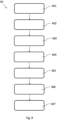
- Fig. 9 shows a flow chart for a method M for severing non-woven-in sections 52 of threads or filaments 5 woven in textile ribbons 4 according to a further embodiment of the invention.
- the method M comprises the step of providing M1 a cutting device 100, in particular a cutting device 100 according to any of the preceding claims, and a textile ribbon 4 having a metallized thread or filament 5 quasi-endlessly woven/non-woven in the fabric of the ribbon 4.
- the method M comprises the step of conveying M2 the textile ribbon 4 in the ribbon conveying table 1 in the conveying direction A.
- the cutting assemblies 2 and the sliding spacers 3 might be in a first position, in which a distal end portion 30 of the sliding spacers 3 contacts the fabric.
- the distal end portion 30 may slide over the fabric of the textile ribbon 4 and the metallized thread or filament 5 woven in the fabric of the textile ribbon in the woven sections 51 without damaging the metallized thread or filament 5 or the textile ribbon 4.
- the sliding spacer 3 In case of a force applying on the sliding spacer 3, in particular on the distal end portion 30 or the elongated body 31, the force being above a defined threshold for a holding force of the solenoid 33, the sliding spacer 3 would be disconnect from the extension arm 34 at the solenoid 33.
- the method M further comprises the step of stopping M3 the ribbon 4 after conveying the ribbon 4 a calculated amount of travel.
- the calculated amount of travel may be based on a reference position of the metallized thread or filament 5 in the fabric sensed by a sensor 7 and a predetermined length L of the woven/non-woven-in sections 51, 52 of the metallized thread or filament 5 in the fabric.
- the sensor 7 is in particular configured as a capacitive, inductive, magnetic field or optical sensor.
- the sensor 7 could sense the reference position by being triggered to a characteristic point of the metallized thread or filament 5 which passes the sensor 7 such as the edge 50 of the non-woven-in sections 52 or a specific inductively marked point of the ribbon 4, for example marked by a specific metallized piece woven in the fabric of the ribbon 4 besides the metallized thread or filament 5 that triggers the sensor 7.
- the method M comprises the step of traveling M4 the cutting assemblies 2 and the sliding spacers 3 from the first position to a second position, wherein the sliding spacers 3 slide between the metallized thread or filament 5 and the fabric of the ribbon 4 at the edges 50 of the non-woven-in section 52 causing the metallized thread or filament 5 to lift away from the fabric.
- the sliding spacers 3 with its distal end portion 30 contacting the fabric may slide basically linear transverse to the conveying direction A of the stopped ribbon 4, wherein the non-woven section 52 of the metallized thread or filament 5 can be lifted along an upper surface 32 of the sliding spacers 3, wherein the upper surface 32 faces away from the fabric and extends from the fabric in an angle between 10° to 80°, preferably between 35° to 55° with regard to a conveying plane of the ribbon conveying table 1.
- the method M comprises the step of simultaneously performing M5 a cutting action for severing a non-woven-in section 52 of the metallized thread or filament 5 from the fabric of the ribbon 4 at the edges 50 of the non-woven-in section 52.
- the cutting action may be initiated by a control unit which can be electronically coupled to at least some components of the cutting device 100, in particular the travel drive 6, the sensor 7, the ribbon conveying drive and the actuators 22.
- the cutting action may be performed in the second position of the cutting assemblies 2 and the sliding spacers 3.
- the actuators 22 simultaneously move the movable scissor blades 21 while the metallized thread or filament 5 is lifted by the sliding spacers 3 and a portion of the metallized thread or filament extending between the sliding spacer 3 and the edge 50 is arranged inside the fixed and the movable scissor blade 20, 21, thereby cutting the metallized thread or filament 5 at the edges 50 of the non-woven-in section 52.
- the method M may further comprise the step of adjusting M6 the distance between the cutting assemblies 2 to a length of the non-woven section 52 of the metallized thread or filament 5 in the fabric via a tool connecting assembly10, in particular a spindle or a shaft, in an axis parallel to the conveying direction A of the ribbon 4. Additionally or optional, the step of adjusting M6 may also include adjusting M6 the distance between the sliding spacers 3 to a length of the non-woven section 52 of the metallized thread or filament 5 in the fabric via a tool connecting assembly10, in particular a spindle or a shaft, in an axis parallel to the conveying direction A of the ribbon 4.
- step of adjusting M6 may include adjusting M6 the position of the cutting assemblies 2 to a position of the edges 50 of the non-woven section 52 of the metallized thread or filament 5 in the fabric via a tool connecting assembly10, in particular a spindle or a shaft, in an axis parallel to the conveying direction A of the ribbon 4.
- the method M may further comprise the step of removing M7 the severed metallized thread or filament 5 from the ribbon conveying table 1 where the cutting action is performed by an air stream generated by an air stream generator 12 and streaming over the ribbon conveying table 1.
- the air stream can be generated constantly or time by the time, in particular every time after the cutting action had been performed.
Landscapes
- Engineering & Computer Science (AREA)
- Textile Engineering (AREA)
- Treatment Of Fiber Materials (AREA)
Claims (17)
- Schneidvorrichtung (100) zum Trennen nicht eingewebter Abschnitte (52) von in textilen Bändern (4) eingewebten Fäden oder Filamenten (5), wobei die Vorrichtung Folgendes umfasst:einen Bandtransporttisch (1), der zum Transportieren eines textilen Bandes (4) konfiguriert ist, das einen metallisierten Faden oder ein metallisiertes Filament (5) aufweist, das quasi endlos in das Gewebe des Bandes (4) eingewebt/nicht eingewebt ist;einen Bandtransportantrieb, der dazu konfiguriert ist, das Band (4) in eine Transportrichtung (A) zu transportieren,mindestens zwei Schneidanordnungen (2), die entlang der Transportrichtung (A) des textilen Bandes (4) voneinander beabstandet sind, wobei die mindestens zwei Schneidanordnungen (2) dazu konfiguriert sind, gleichzeitig einen Schneidvorgang zum Trennen eines nicht eingewebten Abschnitts (52) des metallisierten Fadens oder Filaments (5) von dem Gewebe des Bandes (4) durchzuführen; undmindestens zwei gleitende Abstandshalter (3), die entlang der Transportrichtung (A) des textilen Bandes (4) voneinander beabstandet sind, wobei die mindestens zwei gleitenden Abstandshalter (3) jeweils mit einer jeweiligen der mindestens zwei Schneidanordnungen (2) verbunden sind, die Oberfläche des Bandes (4) berühren und dazu konfiguriert sind, sich an den Kanten (50) der nicht eingewebten Abschnitte (52) gleitend zwischen dem metallisierten Faden oder Filament (5) und dem Gewebe des Bandes (4) zu bewegen, um den Schneidvorgang der mindestens zwei Schneidanordnungen (2) zu erleichtern, wobei die Schneidanordnungen (2) und/oder die gleitenden Abstandshalter (3) über eine Werkzeugverbindungsanordnung (10), insbesondere eine Spindel oder eine Welle, kinematisch verbunden sind, sodass die Position und/oder der Abstand zwischen den Schneidanordnungen (2) und/oder den gleitenden Abstandshaltern (3) in einer Achse, die parallel zu der Transportrichtung (A) des Bandes (4) ist, verstellbar sind.
- Schneidvorrichtung (100) nach Anspruch 1, wobei die gleitenden Abstandshalter (3) einen distalen Endabschnitt (30), der beim Transportieren des textilen Bandes (4) das Gewebe berührt, und einen länglichen Körper (31) aufweisen, der sich von dem distalen Endabschnitt (30) in eine Richtung erstreckt, die im Wesentlichen senkrecht zu der Transportrichtung (A) des Bandes (4) ist.
- Schneidvorrichtung (100) nach Anspruch 2, wobei der längliche Körper (31) eine obere Oberfläche (32) enthält, die von dem Gewebe abgewandt ist und sich von dem Gewebe in einem Winkel zwischen 10° und 80°, vorzugsweise zwischen 35° und 55°, in Bezug auf eine Transportebene des Bandtransporttisches (1) erstreckt.
- Schneidvorrichtung (100) nach einem der vorhergehenden Ansprüche, wobei die gleitenden Abstandshalter (3) entlang der Transportrichtung (A) des Bandes (4) näher beieinander positioniert sind als die Schneidanordnungen (2) beieinander positioniert sind.
- Schneidvorrichtung (100) nach einem der vorhergehenden Ansprüche, wobei die Schneidanordnungen (2) und die gleitenden Abstandshalter (3) eine erste Position, in der das Band (4) in der Transportrichtung (A) transportierbar ist, und eine zweite Position aufweisen, wobei in der zweiten Position der metallisierte Faden oder das metallisierte Filament (5) durch die gleitenden Abstandshalter (3), die zwischen dem metallisierten Faden oder Filament (5) und dem Gewebe positioniert sind, von dem Gewebe weg abgehoben ist.
- Schneidvorrichtung (100) nach Anspruch 5, wobei ein Fahrweg von der ersten Position zu der zweiten Position der Schneidanordnungen (2) im Wesentlichen linear quer zu der Transportrichtung (A) des Bandes (4) ist.
- Schneidvorrichtung (100) nach Anspruch 6, ferner umfassend:
einen Fahrantrieb (6), insbesondere einen pneumatischen, hydraulischen oder elektromechanischen Zylinder, der mit den Schneidanordnungen (2) und den gleitenden Abstandshaltern (3) gekoppelt ist und dazu konfiguriert ist, mindestens eines oder jedes von den Schneidanordnungen (2) und den gleitenden Abstandshaltern (3) durch eine oszillierende Bewegung entlang des Fahrwegs anzutreiben. - Schneidvorrichtung (100) nach einem der vorhergehenden Ansprüche, ferner umfassend:einen Sensor (7), insbesondere einen kapazitiven, induktiven, Magnetfeld- oder optischen Sensor, der dazu konfiguriert ist, Referenzpositionen des metallisierten Fadens oder Filaments (5) in dem Gewebe zu erfassen; undeinen Bandtransportantrieb, der dazu konfiguriert ist, das Band (4) in der Transportrichtung (A) über eine Fahrwegstrecke zu transportieren, die auf den erfassten Referenzpositionen des metallisierten Fadens oder Filaments (5) in dem Gewebe und einer vorbestimmten Länge (L) der gewebten/nicht gewebten Abschnitte (51, 52) des metallisierten Fadens oder Filaments (5) in dem Gewebe basiert.
- Schneidvorrichtung (100) nach einem der vorhergehenden Ansprüche, ferner umfassend:
mindestens zwei Rollen (8) für textiles Band, die zum Aufnehmen des textilen Bandes (4) konfiguriert sind, wobei in Bezug auf die Transportrichtung (A) des Bandes (4) mindestens eine der mindestens zwei Rollen (8) für textiles Band vor und mindestens eine der mindestens zwei Rollen (8) für textiles Band nach den Schneidanordnungen (2) und den gleitenden Abstandshaltern (3) positioniert ist. - Schneidvorrichtung (100) nach einem der vorhergehenden Ansprüche, ferner umfassend:
eine Qualitätssicherungsvorrichtung (9) zum Sicherstellen, dass nicht eingewebte Abschnitte (52) des metallisierten Fadens oder Filaments (5) von dem Gewebe des Bandes (4) vollständig getrennt sind, wobei die Qualitätssicherungsvorrichtung (9) in Bezug auf die Transportrichtung (A) des Bandes (4) stromabwärts der Schneidanordnungen (2) und der gleitenden Abstandshalter (3) positioniert ist. - Schneidvorrichtung (100) nach einem der vorhergehenden Ansprüche, wobei die Schneidanordnungen (2) als Scheren mit jeweils einem feststehenden Scherenblatt (20) und einem beweglichen Scherenblatt (21) konfiguriert sind, wobei die beweglichen Scherenblätter (21) mit einem Aktuator (22), insbesondere einem pneumatischen, hydraulischen oder elektromechanischen Zylinder, gekoppelt sind.
- Schneidvorrichtung (100) nach einem der vorhergehenden Ansprüche, ferner umfassend:
eine Stützstruktur (11), die dazu konfiguriert ist, die Schneidanordnungen (2) und die gleitenden Abstandshalter (3) mechanisch zu stützen, und an dem Bandtransporttisch (1) montiert ist, wobei sie vorzugsweise um eine Achse (W) schwenkbar an dem Bandtransporttisch (1) montiert ist, die parallel zu der Transportrichtung (A) des Bandes (4) ist. - Verfahren (M) zum Trennen nicht eingewebter Abschnitte (52) von in textilen Bändern (4) eingewebten Fäden oder Filamenten (5), wobei das Verfahren (M) die folgenden Schritte umfasst: Bereitstellen (M1) einer Schneidvorrichtung (100), insbesondere einer Schneidvorrichtung (100) nach einem der vorhergehenden Ansprüche, und eines textilen Bandes (4) mit einem in das Gewebe des Bandes (4) quasi endlos eingewebten/nicht eingewebten metallisierten Faden oder Filament (5);Transportieren (M2) des textilen Bandes (4) in dem Bandtransporttisch (1) unter Verwendung eines Bandtransportantriebs, der zum Transportieren des Bandes (4) in einer Transportrichtung (A) konfiguriert ist;Anhalten (M3) des Bandes (4), nachdem das Band (4) eine berechnete Fahrwegstrecke transportiert wurde;Fahren (M4) der Schneidanordnungen (2) und der gleitenden Abstandshalter (3) von einer ersten Position in eine zweite Position, wobei die gleitenden Abstandshalter (3) zwischen dem metallisierten Faden oder Filament (5) und dem Gewebe des Bandes (4) an den Kanten (50) des nicht eingewebten Abschnitts (52) gleiten, wodurch bewirkt wird, dass sich der metallisierte Faden oder das metallisierte Filament (5) von dem Gewebe weg abhebt;gleichzeitiges Durchführen (M5) eines Schneidvorgangs zum Trennen eines nicht eingewebten Abschnitts (52) des metallisierten Fadens oder Filaments (5) von dem Gewebe des Bandes (4) an den Kanten (50) des nicht eingewebten Abschnitts (52); undVerstellen (M6) der Position von und/oder des Abstandes zwischen den Schneidanordnungen (2) und/oder den gleitenden Abstandshaltern (3) auf eine Länge des nicht eingewebten Abschnitts (52) des metallisierten Fadens oder Filaments (5) in dem Gewebe über eine Werkzeugverbindungsanordnung (10), insbesondere eine Spindel oder eine Welle, in einer Achse, die parallel zu der Transportrichtung (A) des Bandes (4) ist.
- Verfahren (M) nach Anspruch 13, wobei sich während des Schritts des Transportierens (M2) die Schneidanordnungen (2) und die gleitenden Abstandshalter (3) in einer ersten Position befinden, in der ein distaler Endabschnitt (30) der gleitenden Abstandshalter (3) das Gewebe berührt.
- Verfahren (M) nach Anspruch 13 oder 14, wobei die berechnete Fahrwegstrecke auf einer durch einen Sensor (7), insbesondere einen kapazitiven, induktiven, Magnetfeld- oder optischen Sensor, erfassten Referenzposition des metallisierten Fadens oder Filaments (5) in dem Gewebe und einer vorbestimmten Länge (L) der gewebten/nicht gewebten Abschnitte (51, 52) des metallisierten Fadens oder Filaments (5) in dem Gewebe basiert.
- Verfahren (M) nach einem der Ansprüche 13 bis 15, wobei bei dem Schritt des Fahrens (M4) die gleitenden Abstandshalter (3), die mit ihrem distalen Endabschnitt (30) das Gewebe berühren, im Wesentlichen linear quer zu der Transportrichtung (A) des angehaltenen Bandes (4) gleiten, wobei der nicht gewebte Abschnitt (52) des metallisierten Fadens oder Filaments (5) entlang einer oberen Oberfläche (32) der gleitenden Abstandshalter (3) angehoben wird, wobei die obere Oberfläche (32) von dem Gewebe abgewandt ist und sich von dem Gewebe in einem Winkel zwischen 10° und 80°, vorzugsweise zwischen 35° und 55°, in Bezug auf eine Transportebene des Bandtransporttisches (1) erstreckt.
- Verfahren (M) nach einem der Ansprüche 13 bis 16, ferner umfassend den Schritt eines Entfernens (M7) des getrennten metallisierten Fadens oder Filaments (5) von dem Bandtransporttisch (1), wobei der Schneidvorgang durch einen Luftstrom ausgeführt wird, der durch einen Luftstromgenerator (12) erzeugt wird und über den Bandtransporttisch (1) strömt.
Applications Claiming Priority (1)
| Application Number | Priority Date | Filing Date | Title |
|---|---|---|---|
| PCT/EP2020/077188 WO2022069015A1 (en) | 2020-09-29 | 2020-09-29 | Cutting device and method for severing non-woven-in sections of threads or filaments woven in textile ribbons |
Publications (2)
| Publication Number | Publication Date |
|---|---|
| EP4222304A1 EP4222304A1 (de) | 2023-08-09 |
| EP4222304B1 true EP4222304B1 (de) | 2025-01-08 |
Family
ID=72717855
Family Applications (1)
| Application Number | Title | Priority Date | Filing Date |
|---|---|---|---|
| EP20785711.1A Active EP4222304B1 (de) | 2020-09-29 | 2020-09-29 | Schneidvorrichtung und verfahren zum durchtrennen von in textilen bändern gewebten vliesabschnitten aus fäden oder filamenten |
Country Status (8)
| Country | Link |
|---|---|
| US (1) | US12442118B2 (de) |
| EP (1) | EP4222304B1 (de) |
| JP (1) | JP7642802B2 (de) |
| KR (1) | KR20230074200A (de) |
| CN (1) | CN116529434B (de) |
| CA (1) | CA3193850A1 (de) |
| MX (1) | MX2023003398A (de) |
| WO (1) | WO2022069015A1 (de) |
Families Citing this family (2)
| Publication number | Priority date | Publication date | Assignee | Title |
|---|---|---|---|---|
| CN116752337A (zh) * | 2023-06-09 | 2023-09-15 | 四川祥和鸟服饰有限公司 | 一种服饰面料裁切设备及裁切方法 |
| CN117564493A (zh) * | 2023-10-17 | 2024-02-20 | 浙江叮当猫校服有限公司 | 一种排汗清爽型校服面料制备设备及制备工艺 |
Family Cites Families (17)
| Publication number | Priority date | Publication date | Assignee | Title |
|---|---|---|---|---|
| US1002415A (en) * | 1909-10-25 | 1911-09-05 | Curtis & Marble Machine Company | Float-thread cutter. |
| US1752611A (en) * | 1929-04-27 | 1930-04-01 | Seekonk Lace Company | Thread cutter |
| US2594918A (en) * | 1950-07-06 | 1952-04-29 | Parks & Woolson Machine Co | Selvage finishing mechanism |
| FR1282181A (fr) * | 1960-12-09 | 1962-01-19 | Lace Clipping Co | Machine à découper la dentelle et les produits textiles analogues |
| US3772127A (en) * | 1972-01-07 | 1973-11-13 | A James | Thread fusing and severing apparatus |
| JP3343929B2 (ja) * | 1992-03-24 | 2002-11-11 | 石川島播磨重工業株式会社 | テキスタイルコードの横糸処理装置 |
| US5406872A (en) * | 1992-07-28 | 1995-04-18 | Mim Industries, Inc. | Side-by-side programmable feed system |
| DE102004003461C5 (de) | 2004-01-22 | 2009-11-19 | ASTRA Gesellschaft für Asset Management mbH & Co. KG | Textilmaterial mit einem HF-Transponder |
| KR20120111427A (ko) * | 2011-03-31 | 2012-10-10 | 자인섬유 (주) | 제직기의 직물표면 절단장치 |
| DE102011106648A1 (de) | 2011-07-05 | 2013-01-10 | Giesecke & Devrient Gmbh | Tragbarer Datenträger mit Antenne |
| CN104126040B (zh) * | 2012-01-24 | 2017-06-09 | 耐克创新有限合伙公司 | 编织修整装置 |
| WO2016181298A1 (en) * | 2015-05-14 | 2016-11-17 | Morgan Tecnica S.P.A. | Machine for spreading fabric |
| WO2017216817A1 (en) * | 2016-06-15 | 2017-12-21 | Visentin, Liliana | Improved shearing machine |
| CN108085913B (zh) * | 2017-11-22 | 2023-09-05 | 广东天海花边有限公司 | 一种智能跟边护边的剪线机 |
| CN208440899U (zh) * | 2018-05-04 | 2019-01-29 | 四川省宜宾圣山服装家纺有限公司 | 一种具有切口功能的横切机 |
| CN109338651B (zh) * | 2018-12-18 | 2021-05-11 | 江苏工程职业技术学院 | 一种双动力式机织面料自动纬纱剪花机构 |
| CN114714730B (zh) * | 2022-03-24 | 2023-03-21 | 宁波新润纺织品有限公司 | 可撕开成片的连续性涤纶纤维纺织布、加工设备及方法 |
-
2020
- 2020-09-29 EP EP20785711.1A patent/EP4222304B1/de active Active
- 2020-09-29 WO PCT/EP2020/077188 patent/WO2022069015A1/en not_active Ceased
- 2020-09-29 CN CN202080107462.7A patent/CN116529434B/zh active Active
- 2020-09-29 CA CA3193850A patent/CA3193850A1/en active Pending
- 2020-09-29 MX MX2023003398A patent/MX2023003398A/es unknown
- 2020-09-29 JP JP2023519669A patent/JP7642802B2/ja active Active
- 2020-09-29 KR KR1020237013237A patent/KR20230074200A/ko not_active Withdrawn
- 2020-09-29 US US18/021,925 patent/US12442118B2/en active Active
Also Published As
| Publication number | Publication date |
|---|---|
| MX2023003398A (es) | 2023-03-31 |
| JP7642802B2 (ja) | 2025-03-10 |
| KR20230074200A (ko) | 2023-05-26 |
| EP4222304A1 (de) | 2023-08-09 |
| CA3193850A1 (en) | 2022-04-07 |
| JP2023543077A (ja) | 2023-10-12 |
| CN116529434B (zh) | 2025-08-05 |
| US12442118B2 (en) | 2025-10-14 |
| US20230304208A1 (en) | 2023-09-28 |
| CN116529434A (zh) | 2023-08-01 |
| WO2022069015A1 (en) | 2022-04-07 |
Similar Documents
| Publication | Publication Date | Title |
|---|---|---|
| EP4222304B1 (de) | Schneidvorrichtung und verfahren zum durchtrennen von in textilen bändern gewebten vliesabschnitten aus fäden oder filamenten | |
| CN101678518B (zh) | 用于皮革的切割机 | |
| CN107405794B (zh) | 具有刀具的用于分割至少一根纤维的切割单元 | |
| CN113905861B (zh) | 用于引入分离装置的系统及膜吹塑设备以及该设备中制造并提供至少两个塑料膜幅材的方法 | |
| JP7105869B2 (ja) | 糸群を糸掛けしかつ分離するための方法ならびに溶融紡糸装置 | |
| CN101016656A (zh) | 用于制造和贮放丝束的方法和装置 | |
| US8152090B2 (en) | Take-up device | |
| WO2019011548A1 (de) | Schmelzspinnvorrichtung | |
| CZ280498B6 (cs) | Zařízení pro oddělování jednotlivých nitěnek pro stroje pro navádění osnovních nití | |
| CN101590652B (zh) | 一种片式元件的全自动分割机及其使用方法 | |
| EP2815859B1 (de) | Längsschneideranordnung einer Längschneiderwickel einer Faserbahn-Herstellungslinie | |
| KR20020082481A (ko) | 절단된 열가소성 얀을 제조하기 위한 시스템 | |
| JP6461705B2 (ja) | 糸切断装置 | |
| JPH0735625B2 (ja) | たて糸の切れ端分離方法およびその装置 | |
| BR112023005947B1 (pt) | Dispositivo de corte e método para separar seções não tecidas de fios ou filamentos tecidos em fitas têxteis | |
| US12473168B2 (en) | Unwinder with automatic switching of the unwinding roll | |
| US12486134B2 (en) | Unwinder of thin ply product wound on a roll, with facilitated extraction of the roll | |
| CN112823220A (zh) | 熔纺装置操作方法和熔纺装置 | |
| CN110155706A (zh) | 多工位输送装置及食品罐打码机 | |
| CN111958132B (zh) | 一种纺织面料自动切割系统 | |
| CN220920033U (zh) | 卡带检测装置 | |
| JPH02216244A (ja) | 織機の破断したたて糸を自動的に修復するための装置及び方法 | |
| CN1654296A (zh) | 用于连接纱线的机器 | |
| KR20230020791A (ko) | 실패의 잔사제거장치 | |
| CN216836377U (zh) | 一种卷盘物料的在线自动传送装置 |
Legal Events
| Date | Code | Title | Description |
|---|---|---|---|
| STAA | Information on the status of an ep patent application or granted ep patent |
Free format text: STATUS: UNKNOWN |
|
| STAA | Information on the status of an ep patent application or granted ep patent |
Free format text: STATUS: THE INTERNATIONAL PUBLICATION HAS BEEN MADE |
|
| PUAI | Public reference made under article 153(3) epc to a published international application that has entered the european phase |
Free format text: ORIGINAL CODE: 0009012 |
|
| STAA | Information on the status of an ep patent application or granted ep patent |
Free format text: STATUS: REQUEST FOR EXAMINATION WAS MADE |
|
| 17P | Request for examination filed |
Effective date: 20230329 |
|
| AK | Designated contracting states |
Kind code of ref document: A1 Designated state(s): AL AT BE BG CH CY CZ DE DK EE ES FI FR GB GR HR HU IE IS IT LI LT LU LV MC MK MT NL NO PL PT RO RS SE SI SK SM TR |
|
| DAV | Request for validation of the european patent (deleted) | ||
| DAX | Request for extension of the european patent (deleted) | ||
| GRAP | Despatch of communication of intention to grant a patent |
Free format text: ORIGINAL CODE: EPIDOSNIGR1 |
|
| STAA | Information on the status of an ep patent application or granted ep patent |
Free format text: STATUS: GRANT OF PATENT IS INTENDED |
|
| INTG | Intention to grant announced |
Effective date: 20240510 |
|
| GRAJ | Information related to disapproval of communication of intention to grant by the applicant or resumption of examination proceedings by the epo deleted |
Free format text: ORIGINAL CODE: EPIDOSDIGR1 |
|
| STAA | Information on the status of an ep patent application or granted ep patent |
Free format text: STATUS: REQUEST FOR EXAMINATION WAS MADE |
|
| INTC | Intention to grant announced (deleted) | ||
| GRAP | Despatch of communication of intention to grant a patent |
Free format text: ORIGINAL CODE: EPIDOSNIGR1 |
|
| STAA | Information on the status of an ep patent application or granted ep patent |
Free format text: STATUS: GRANT OF PATENT IS INTENDED |
|
| INTG | Intention to grant announced |
Effective date: 20240816 |
|
| GRAS | Grant fee paid |
Free format text: ORIGINAL CODE: EPIDOSNIGR3 |
|
| GRAA | (expected) grant |
Free format text: ORIGINAL CODE: 0009210 |
|
| STAA | Information on the status of an ep patent application or granted ep patent |
Free format text: STATUS: THE PATENT HAS BEEN GRANTED |
|
| P01 | Opt-out of the competence of the unified patent court (upc) registered |
Free format text: CASE NUMBER: APP_60453/2024 Effective date: 20241108 |
|
| AK | Designated contracting states |
Kind code of ref document: B1 Designated state(s): AL AT BE BG CH CY CZ DE DK EE ES FI FR GB GR HR HU IE IS IT LI LT LU LV MC MK MT NL NO PL PT RO RS SE SI SK SM TR |
|
| REG | Reference to a national code |
Ref country code: GB Ref legal event code: FG4D |
|
| REG | Reference to a national code |
Ref country code: CH Ref legal event code: EP |
|
| REG | Reference to a national code |
Ref country code: DE Ref legal event code: R096 Ref document number: 602020044560 Country of ref document: DE |
|
| REG | Reference to a national code |
Ref country code: IE Ref legal event code: FG4D |
|
| REG | Reference to a national code |
Ref country code: LT Ref legal event code: MG9D |
|
| REG | Reference to a national code |
Ref country code: NL Ref legal event code: MP Effective date: 20250108 |
|
| REG | Reference to a national code |
Ref country code: AT Ref legal event code: MK05 Ref document number: 1758389 Country of ref document: AT Kind code of ref document: T Effective date: 20250108 |
|
| PG25 | Lapsed in a contracting state [announced via postgrant information from national office to epo] |
Ref country code: NL Free format text: LAPSE BECAUSE OF FAILURE TO SUBMIT A TRANSLATION OF THE DESCRIPTION OR TO PAY THE FEE WITHIN THE PRESCRIBED TIME-LIMIT Effective date: 20250108 |
|
| PG25 | Lapsed in a contracting state [announced via postgrant information from national office to epo] |
Ref country code: RS Free format text: LAPSE BECAUSE OF FAILURE TO SUBMIT A TRANSLATION OF THE DESCRIPTION OR TO PAY THE FEE WITHIN THE PRESCRIBED TIME-LIMIT Effective date: 20250408 |
|
| PG25 | Lapsed in a contracting state [announced via postgrant information from national office to epo] |
Ref country code: FI Free format text: LAPSE BECAUSE OF FAILURE TO SUBMIT A TRANSLATION OF THE DESCRIPTION OR TO PAY THE FEE WITHIN THE PRESCRIBED TIME-LIMIT Effective date: 20250108 |
|
| PG25 | Lapsed in a contracting state [announced via postgrant information from national office to epo] |
Ref country code: PL Free format text: LAPSE BECAUSE OF FAILURE TO SUBMIT A TRANSLATION OF THE DESCRIPTION OR TO PAY THE FEE WITHIN THE PRESCRIBED TIME-LIMIT Effective date: 20250108 |
|
| PG25 | Lapsed in a contracting state [announced via postgrant information from national office to epo] |
Ref country code: ES Free format text: LAPSE BECAUSE OF FAILURE TO SUBMIT A TRANSLATION OF THE DESCRIPTION OR TO PAY THE FEE WITHIN THE PRESCRIBED TIME-LIMIT Effective date: 20250108 |
|
| PG25 | Lapsed in a contracting state [announced via postgrant information from national office to epo] |
Ref country code: NO Free format text: LAPSE BECAUSE OF FAILURE TO SUBMIT A TRANSLATION OF THE DESCRIPTION OR TO PAY THE FEE WITHIN THE PRESCRIBED TIME-LIMIT Effective date: 20250408 Ref country code: IS Free format text: LAPSE BECAUSE OF FAILURE TO SUBMIT A TRANSLATION OF THE DESCRIPTION OR TO PAY THE FEE WITHIN THE PRESCRIBED TIME-LIMIT Effective date: 20250508 |
|
| PG25 | Lapsed in a contracting state [announced via postgrant information from national office to epo] |
Ref country code: HR Free format text: LAPSE BECAUSE OF FAILURE TO SUBMIT A TRANSLATION OF THE DESCRIPTION OR TO PAY THE FEE WITHIN THE PRESCRIBED TIME-LIMIT Effective date: 20250108 |
|
| PG25 | Lapsed in a contracting state [announced via postgrant information from national office to epo] |
Ref country code: PT Free format text: LAPSE BECAUSE OF FAILURE TO SUBMIT A TRANSLATION OF THE DESCRIPTION OR TO PAY THE FEE WITHIN THE PRESCRIBED TIME-LIMIT Effective date: 20250508 Ref country code: LV Free format text: LAPSE BECAUSE OF FAILURE TO SUBMIT A TRANSLATION OF THE DESCRIPTION OR TO PAY THE FEE WITHIN THE PRESCRIBED TIME-LIMIT Effective date: 20250108 |
|
| PG25 | Lapsed in a contracting state [announced via postgrant information from national office to epo] |
Ref country code: BG Free format text: LAPSE BECAUSE OF FAILURE TO SUBMIT A TRANSLATION OF THE DESCRIPTION OR TO PAY THE FEE WITHIN THE PRESCRIBED TIME-LIMIT Effective date: 20250108 Ref country code: GR Free format text: LAPSE BECAUSE OF FAILURE TO SUBMIT A TRANSLATION OF THE DESCRIPTION OR TO PAY THE FEE WITHIN THE PRESCRIBED TIME-LIMIT Effective date: 20250409 |
|
| PG25 | Lapsed in a contracting state [announced via postgrant information from national office to epo] |
Ref country code: AT Free format text: LAPSE BECAUSE OF FAILURE TO SUBMIT A TRANSLATION OF THE DESCRIPTION OR TO PAY THE FEE WITHIN THE PRESCRIBED TIME-LIMIT Effective date: 20250108 |
|
| PG25 | Lapsed in a contracting state [announced via postgrant information from national office to epo] |
Ref country code: SE Free format text: LAPSE BECAUSE OF FAILURE TO SUBMIT A TRANSLATION OF THE DESCRIPTION OR TO PAY THE FEE WITHIN THE PRESCRIBED TIME-LIMIT Effective date: 20250108 |
|
| PG25 | Lapsed in a contracting state [announced via postgrant information from national office to epo] |
Ref country code: SM Free format text: LAPSE BECAUSE OF FAILURE TO SUBMIT A TRANSLATION OF THE DESCRIPTION OR TO PAY THE FEE WITHIN THE PRESCRIBED TIME-LIMIT Effective date: 20250108 |
|
| REG | Reference to a national code |
Ref country code: DE Ref legal event code: R097 Ref document number: 602020044560 Country of ref document: DE |
|
| PG25 | Lapsed in a contracting state [announced via postgrant information from national office to epo] |
Ref country code: DK Free format text: LAPSE BECAUSE OF FAILURE TO SUBMIT A TRANSLATION OF THE DESCRIPTION OR TO PAY THE FEE WITHIN THE PRESCRIBED TIME-LIMIT Effective date: 20250108 |
|
| PGFP | Annual fee paid to national office [announced via postgrant information from national office to epo] |
Ref country code: DE Payment date: 20250808 Year of fee payment: 6 |
|
| PGFP | Annual fee paid to national office [announced via postgrant information from national office to epo] |
Ref country code: GB Payment date: 20250814 Year of fee payment: 6 |
|
| PGFP | Annual fee paid to national office [announced via postgrant information from national office to epo] |
Ref country code: FR Payment date: 20250808 Year of fee payment: 6 |
|
| PG25 | Lapsed in a contracting state [announced via postgrant information from national office to epo] |
Ref country code: CZ Free format text: LAPSE BECAUSE OF FAILURE TO SUBMIT A TRANSLATION OF THE DESCRIPTION OR TO PAY THE FEE WITHIN THE PRESCRIBED TIME-LIMIT Effective date: 20250108 Ref country code: EE Free format text: LAPSE BECAUSE OF FAILURE TO SUBMIT A TRANSLATION OF THE DESCRIPTION OR TO PAY THE FEE WITHIN THE PRESCRIBED TIME-LIMIT Effective date: 20250108 |
|
| PG25 | Lapsed in a contracting state [announced via postgrant information from national office to epo] |
Ref country code: RO Free format text: LAPSE BECAUSE OF FAILURE TO SUBMIT A TRANSLATION OF THE DESCRIPTION OR TO PAY THE FEE WITHIN THE PRESCRIBED TIME-LIMIT Effective date: 20250108 |
|
| PG25 | Lapsed in a contracting state [announced via postgrant information from national office to epo] |
Ref country code: SK Free format text: LAPSE BECAUSE OF FAILURE TO SUBMIT A TRANSLATION OF THE DESCRIPTION OR TO PAY THE FEE WITHIN THE PRESCRIBED TIME-LIMIT Effective date: 20250108 |
|
| PLBE | No opposition filed within time limit |
Free format text: ORIGINAL CODE: 0009261 |
|
| STAA | Information on the status of an ep patent application or granted ep patent |
Free format text: STATUS: NO OPPOSITION FILED WITHIN TIME LIMIT |
|
| 26N | No opposition filed |
Effective date: 20251009 |
|
| PG25 | Lapsed in a contracting state [announced via postgrant information from national office to epo] |
Ref country code: IT Free format text: LAPSE BECAUSE OF FAILURE TO SUBMIT A TRANSLATION OF THE DESCRIPTION OR TO PAY THE FEE WITHIN THE PRESCRIBED TIME-LIMIT Effective date: 20250108 |