EP4219281A2 - Dérailleur arrière pour montage coaxial - Google Patents
Dérailleur arrière pour montage coaxial Download PDFInfo
- Publication number
- EP4219281A2 EP4219281A2 EP23020162.6A EP23020162A EP4219281A2 EP 4219281 A2 EP4219281 A2 EP 4219281A2 EP 23020162 A EP23020162 A EP 23020162A EP 4219281 A2 EP4219281 A2 EP 4219281A2
- Authority
- EP
- European Patent Office
- Prior art keywords
- axle
- rear derailleur
- adapter
- base element
- arm
- Prior art date
- Legal status (The legal status is an assumption and is not a legal conclusion. Google has not performed a legal analysis and makes no representation as to the accuracy of the status listed.)
- Pending
Links
- 230000007246 mechanism Effects 0.000 claims abstract description 62
- 230000008878 coupling Effects 0.000 claims abstract description 7
- 238000010168 coupling process Methods 0.000 claims abstract description 7
- 238000005859 coupling reaction Methods 0.000 claims abstract description 7
- 230000013011 mating Effects 0.000 abstract 2
- 238000011161 development Methods 0.000 description 18
- 238000013461 design Methods 0.000 description 9
- 239000000463 material Substances 0.000 description 8
- 238000004519 manufacturing process Methods 0.000 description 7
- 230000007704 transition Effects 0.000 description 7
- 230000000694 effects Effects 0.000 description 6
- 230000008901 benefit Effects 0.000 description 5
- 229910052782 aluminium Inorganic materials 0.000 description 4
- XAGFODPZIPBFFR-UHFFFAOYSA-N aluminium Chemical compound [Al] XAGFODPZIPBFFR-UHFFFAOYSA-N 0.000 description 4
- 238000007667 floating Methods 0.000 description 4
- 238000005452 bending Methods 0.000 description 3
- 230000008092 positive effect Effects 0.000 description 3
- RTAQQCXQSZGOHL-UHFFFAOYSA-N Titanium Chemical compound [Ti] RTAQQCXQSZGOHL-UHFFFAOYSA-N 0.000 description 2
- 208000012886 Vertigo Diseases 0.000 description 2
- 238000010276 construction Methods 0.000 description 2
- 230000003993 interaction Effects 0.000 description 2
- 230000002093 peripheral effect Effects 0.000 description 2
- 230000008719 thickening Effects 0.000 description 2
- 229910052719 titanium Inorganic materials 0.000 description 2
- 239000010936 titanium Substances 0.000 description 2
- 241001136792 Alle Species 0.000 description 1
- 229920002430 Fibre-reinforced plastic Polymers 0.000 description 1
- 229910000831 Steel Inorganic materials 0.000 description 1
- 230000006978 adaptation Effects 0.000 description 1
- 239000004411 aluminium Substances 0.000 description 1
- 238000013459 approach Methods 0.000 description 1
- 230000000712 assembly Effects 0.000 description 1
- 238000000429 assembly Methods 0.000 description 1
- 230000005540 biological transmission Effects 0.000 description 1
- 230000008859 change Effects 0.000 description 1
- 230000006835 compression Effects 0.000 description 1
- 238000007906 compression Methods 0.000 description 1
- 230000007423 decrease Effects 0.000 description 1
- 230000001419 dependent effect Effects 0.000 description 1
- 239000011151 fibre-reinforced plastic Substances 0.000 description 1
- 238000009432 framing Methods 0.000 description 1
- 238000012423 maintenance Methods 0.000 description 1
- 229910052751 metal Inorganic materials 0.000 description 1
- 239000002184 metal Substances 0.000 description 1
- 238000000034 method Methods 0.000 description 1
- 230000036316 preload Effects 0.000 description 1
- 238000012545 processing Methods 0.000 description 1
- 239000010959 steel Substances 0.000 description 1
Images


Classifications
-
- B—PERFORMING OPERATIONS; TRANSPORTING
- B62—LAND VEHICLES FOR TRAVELLING OTHERWISE THAN ON RAILS
- B62M—RIDER PROPULSION OF WHEELED VEHICLES OR SLEDGES; POWERED PROPULSION OF SLEDGES OR SINGLE-TRACK CYCLES; TRANSMISSIONS SPECIALLY ADAPTED FOR SUCH VEHICLES
- B62M9/00—Transmissions characterised by use of an endless chain, belt, or the like
- B62M9/04—Transmissions characterised by use of an endless chain, belt, or the like of changeable ratio
- B62M9/06—Transmissions characterised by use of an endless chain, belt, or the like of changeable ratio using a single chain, belt, or the like
- B62M9/10—Transmissions characterised by use of an endless chain, belt, or the like of changeable ratio using a single chain, belt, or the like involving different-sized wheels, e.g. rear sprocket chain wheels selectively engaged by the chain, belt, or the like
- B62M9/12—Transmissions characterised by use of an endless chain, belt, or the like of changeable ratio using a single chain, belt, or the like involving different-sized wheels, e.g. rear sprocket chain wheels selectively engaged by the chain, belt, or the like the chain, belt, or the like being laterally shiftable, e.g. using a rear derailleur
- B62M9/121—Rear derailleurs
- B62M9/125—Mounting the derailleur on the frame
-
- B—PERFORMING OPERATIONS; TRANSPORTING
- B62—LAND VEHICLES FOR TRAVELLING OTHERWISE THAN ON RAILS
- B62K—CYCLES; CYCLE FRAMES; CYCLE STEERING DEVICES; RIDER-OPERATED TERMINAL CONTROLS SPECIALLY ADAPTED FOR CYCLES; CYCLE AXLE SUSPENSIONS; CYCLE SIDE-CARS, FORECARS, OR THE LIKE
- B62K25/00—Axle suspensions
- B62K25/02—Axle suspensions for mounting axles rigidly on cycle frame or fork, e.g. adjustably
-
- B—PERFORMING OPERATIONS; TRANSPORTING
- B62—LAND VEHICLES FOR TRAVELLING OTHERWISE THAN ON RAILS
- B62M—RIDER PROPULSION OF WHEELED VEHICLES OR SLEDGES; POWERED PROPULSION OF SLEDGES OR SINGLE-TRACK CYCLES; TRANSMISSIONS SPECIALLY ADAPTED FOR SUCH VEHICLES
- B62M9/00—Transmissions characterised by use of an endless chain, belt, or the like
- B62M9/04—Transmissions characterised by use of an endless chain, belt, or the like of changeable ratio
- B62M9/06—Transmissions characterised by use of an endless chain, belt, or the like of changeable ratio using a single chain, belt, or the like
- B62M9/10—Transmissions characterised by use of an endless chain, belt, or the like of changeable ratio using a single chain, belt, or the like involving different-sized wheels, e.g. rear sprocket chain wheels selectively engaged by the chain, belt, or the like
- B62M9/12—Transmissions characterised by use of an endless chain, belt, or the like of changeable ratio using a single chain, belt, or the like involving different-sized wheels, e.g. rear sprocket chain wheels selectively engaged by the chain, belt, or the like the chain, belt, or the like being laterally shiftable, e.g. using a rear derailleur
- B62M9/121—Rear derailleurs
- B62M9/124—Mechanisms for shifting laterally
- B62M9/1242—Mechanisms for shifting laterally characterised by the linkage mechanisms
-
- B—PERFORMING OPERATIONS; TRANSPORTING
- B62—LAND VEHICLES FOR TRAVELLING OTHERWISE THAN ON RAILS
- B62M—RIDER PROPULSION OF WHEELED VEHICLES OR SLEDGES; POWERED PROPULSION OF SLEDGES OR SINGLE-TRACK CYCLES; TRANSMISSIONS SPECIALLY ADAPTED FOR SUCH VEHICLES
- B62M9/00—Transmissions characterised by use of an endless chain, belt, or the like
- B62M9/04—Transmissions characterised by use of an endless chain, belt, or the like of changeable ratio
- B62M9/06—Transmissions characterised by use of an endless chain, belt, or the like of changeable ratio using a single chain, belt, or the like
- B62M9/10—Transmissions characterised by use of an endless chain, belt, or the like of changeable ratio using a single chain, belt, or the like involving different-sized wheels, e.g. rear sprocket chain wheels selectively engaged by the chain, belt, or the like
- B62M9/12—Transmissions characterised by use of an endless chain, belt, or the like of changeable ratio using a single chain, belt, or the like involving different-sized wheels, e.g. rear sprocket chain wheels selectively engaged by the chain, belt, or the like the chain, belt, or the like being laterally shiftable, e.g. using a rear derailleur
- B62M9/121—Rear derailleurs
- B62M9/126—Chain guides; Mounting thereof
-
- B—PERFORMING OPERATIONS; TRANSPORTING
- B62—LAND VEHICLES FOR TRAVELLING OTHERWISE THAN ON RAILS
- B62M—RIDER PROPULSION OF WHEELED VEHICLES OR SLEDGES; POWERED PROPULSION OF SLEDGES OR SINGLE-TRACK CYCLES; TRANSMISSIONS SPECIALLY ADAPTED FOR SUCH VEHICLES
- B62M9/00—Transmissions characterised by use of an endless chain, belt, or the like
- B62M9/04—Transmissions characterised by use of an endless chain, belt, or the like of changeable ratio
- B62M9/06—Transmissions characterised by use of an endless chain, belt, or the like of changeable ratio using a single chain, belt, or the like
- B62M9/10—Transmissions characterised by use of an endless chain, belt, or the like of changeable ratio using a single chain, belt, or the like involving different-sized wheels, e.g. rear sprocket chain wheels selectively engaged by the chain, belt, or the like
- B62M9/12—Transmissions characterised by use of an endless chain, belt, or the like of changeable ratio using a single chain, belt, or the like involving different-sized wheels, e.g. rear sprocket chain wheels selectively engaged by the chain, belt, or the like the chain, belt, or the like being laterally shiftable, e.g. using a rear derailleur
- B62M9/121—Rear derailleurs
- B62M9/127—Mounting or guiding of cables
-
- B—PERFORMING OPERATIONS; TRANSPORTING
- B62—LAND VEHICLES FOR TRAVELLING OTHERWISE THAN ON RAILS
- B62M—RIDER PROPULSION OF WHEELED VEHICLES OR SLEDGES; POWERED PROPULSION OF SLEDGES OR SINGLE-TRACK CYCLES; TRANSMISSIONS SPECIALLY ADAPTED FOR SUCH VEHICLES
- B62M9/00—Transmissions characterised by use of an endless chain, belt, or the like
- B62M9/04—Transmissions characterised by use of an endless chain, belt, or the like of changeable ratio
- B62M9/06—Transmissions characterised by use of an endless chain, belt, or the like of changeable ratio using a single chain, belt, or the like
- B62M9/10—Transmissions characterised by use of an endless chain, belt, or the like of changeable ratio using a single chain, belt, or the like involving different-sized wheels, e.g. rear sprocket chain wheels selectively engaged by the chain, belt, or the like
- B62M9/12—Transmissions characterised by use of an endless chain, belt, or the like of changeable ratio using a single chain, belt, or the like involving different-sized wheels, e.g. rear sprocket chain wheels selectively engaged by the chain, belt, or the like the chain, belt, or the like being laterally shiftable, e.g. using a rear derailleur
- B62M9/121—Rear derailleurs
- B62M9/128—Accessories, e.g. protectors
-
- B—PERFORMING OPERATIONS; TRANSPORTING
- B62—LAND VEHICLES FOR TRAVELLING OTHERWISE THAN ON RAILS
- B62M—RIDER PROPULSION OF WHEELED VEHICLES OR SLEDGES; POWERED PROPULSION OF SLEDGES OR SINGLE-TRACK CYCLES; TRANSMISSIONS SPECIALLY ADAPTED FOR SUCH VEHICLES
- B62M9/00—Transmissions characterised by use of an endless chain, belt, or the like
- B62M9/16—Tensioning or adjusting equipment for chains, belts or the like
Definitions
- the invention relates to a rear derailleur for coaxial assembly on a rear wheel axle.
- Rear derailleurs are usually attached to the right dropout of the frame using a derailleur hanger.
- One end of the derailleur hanger is fixed coaxially with the rear wheel axle on the frame and the other end is connected to the base element (also known as the B-knuckle) of the rear derailleur.
- the base element can be rotated about the B axis relative to the derailleur hanger.
- Derailleur hangers differ greatly depending on the manufacturer and the type of attachment. They can be designed in one piece with the frame or be present as a separate component. Separate derailleur hangers are clamped to the frame either via quick-release axles or via quick-release axles. Clamping on the outside of the frame as well as on the inside of the frame is possible.
- the rear derailleur assumes a different position relative to the rear wheel axle and also to the sprocket set, depending on the derailleur hanger used.
- These positional differences in both the axial and radial directions make the rear derailleur design and assembly complicated.
- the rear derailleur must be readjusted.
- the additional component adds tolerances that have a negative effect on the positioning accuracy of the rear derailleur.
- derailleur hangers especially as separate components, are prone to damage and often unstable.
- large sprocket sets and correspondingly large rear derailleur dimensions increased leverage occurs, which is the case with a replaceable
- the rear wheel includes, among other things, a rear wheel hub with a hollow hub axle (also called a hollow axle).
- a separate thru-axle or quick-release axle is routed through the hub axle of the rear wheel hub and clamped to the frame.
- the known rear derailleur usually comprise a base element with a fastening end with an opening for receiving an axle. Similar to a derailleur hanger, the attachment end is attached either to the outside or inside of the frame. For this purpose, it is clamped to the frame using a quick-release axle or quick-release axle.
- these known coaxial designs have shortcomings.
- the object is therefore to provide a rear derailleur that overcomes the disadvantages of the known derailleurs.
- a first aspect of the invention solves the problem with a rear derailleur for coaxial mounting according to claim 1.
- the rear derailleur according to the invention is suitable for coaxial mounting on a rear wheel axle.
- the rear derailleur has a base member (aka B-knuckle), a pivot mechanism, a movable member (aka P-knuckle), and a chain guide assembly.
- the pivoting mechanism connects the base member to the movable member.
- the chain guide assembly is rotatably connected to the movable member about a pivot axis (P-axis).
- the base element comprises a first connection end which can be mounted on the bicycle frame coaxially with the rear wheel axle, and a second connection end for Coupling with the swivel mechanism.
- the first terminal end having a first arm and a second arm spaced apart from each other in the axial direction.
- the two arms are used to attach the base element to the rear wheel axle.
- the advantage of this configuration is that the two spaced-apart arms of the base element ensure stable alignment of the rear derailleur parallel to the plane of rotation of the pinion and thus perpendicular to the rear wheel axle when the rear derailleur is in the assembled state. Tilting of the rear derailleur out of this plane is effectively prevented even with larger forces.
- the two axially spaced attachment points of the base element on the rear wheel axle can absorb the forces acting on the rear derailleur much better than the known rear derailleur with only one attachment end.
- the first arm is located on an axial inner side of a bicycle frame and the second arm is located on an axial outer side of the frame.
- the assembled state means that the rear derailleur is mounted on the frame coaxially to the rear wheel axle A.
- the rear derailleur is mounted on the right dropout of the frame.
- the inside of the frame means the side of the frame pointing in the direction of the sprocket pack.
- the axial outer side means that side of the frame which is opposite the inner side and points away from the sprocket set.
- the first arm has a first centering opening and the second arm has a second centering opening.
- the first arm has an adapter stop surface on its axial outer side.
- the first arm has a hub stop surface on its axial inner side.
- the two abutment surfaces each provide an axial abutment for the parts adjoining the base element in the assembled state.
- Adapter from the outside, and a hub, in particular a hub end cap, from the inside on the base element.
- the first arm has a hub guide on its axial inner side.
- the hub guide facilitates the assembly of the rear wheel because the hub, in particular the hub end cap, can slide into its end position along the hub guide, in particular its guide surfaces which converge.
- the inside of the arm means the side of the arm that points in the direction of the sprocket set when the base element is in the mounted state.
- the outside is the side of the arm facing away from the sprocket set.
- the first arm has an axle opening through which an axle can pass.
- the axle is in particular a quick-release axle or a quick-release axle.
- the diameter of the axle opening must therefore be larger than that of the axle so that it can be passed through.
- the centering opening on the first arm forms the axle opening at the same time.
- the two openings could also be formed separately from one another.
- the second arm of the base element mounted on the outside of the frame can also have an axle opening if the axle projects into the area of the second arm or beyond. This can be the case with quick-release axles.
- the base element has a connection point for a cable deflection. A shift cable coming from the frame is usually routed via the shift linkage to the swivel mechanism.
- the base element has a first mount for a first pivot axis of the pivot mechanism and a second mount for a second pivot axis of the pivot mechanism.
- the inner pivoting arm of the pivoting mechanism is rotatably connected to the base element via the first pivoting axis.
- the outer pivot arm of the pivot mechanism is rotatably connected to the base element via the second pivot axis.
- the pivot axes are each mounted in a receptacle on the base element.
- the axle mounts are aligned in such a way that they can accommodate the pivot axes oriented orthogonally to the rear wheel axle.
- This means that the receptacles or their longitudinal axes are matched to the pivot axes of the pivot mechanism and, like the pivot axes, are each oriented orthogonally to the rear wheel axis.
- An orientation orthogonal to the rear wheel axis means that the longitudinal axes of the first and second mounts of the base element each lie in a plane that intersects the rear wheel axis or a geometric axis A running along the rear wheel axis at a right angle.
- connection point for the cable deflection can either be designed in one piece with the base element or be connected to it as a separate part. The same applies to the inner and outer axle mount.
- the base element itself can also be designed in one piece or in several parts.
- a base element manufactured in one piece from metal, in particular milled from aluminum, is particularly stable and can be manufactured very precisely.
- other materials such as fiber-reinforced plastics can also be used for parts or the entire base element.
- the rear derailleur has an adapter that includes a screw connection.
- the screw connection is formed in particular by a bolt with an external thread and a nut with an internal thread.
- the rear derailleur can be fixed to the frame using the adapter.
- the adapter can be inserted into a frame opening. In other words, the adapter reaches through the frame opening.
- the frame opening can vary depending on the axle used. Thru axles are usually inserted into openings enclosed by the frame. Quick-release axles, on the other hand, are usually inserted into a slot-like opening from below.
- the adapter can be fixed to the frame using the screw connection.
- the adapter has outside diameters at both of its ends, which are dimensioned larger than the diameter of the frame opening.
- One end of the adapter is on the inside of the frame and the other end is on the outside.
- the head of the bolt and the nut are sized larger than the frame opening and fit on the inside and outside of it.
- the nut has a knurled contact surface which, when fully assembled, rests positively and non-positively on the frame.
- the bolt has a bolt body with a contact area and a compensation area.
- the contact area is on the inner diameter of the frame opening.
- the compensating area for example, is tapered and has a little more play compared to the frame opening. Due to the increased play, the bolt and thus the entire adapter can be aligned with respect to the frame opening. Framing inaccuracies can be compensated for in this way.
- the adapter can align itself coaxially with the rear wheel axis A, even if the frame opening axis deviates from it due to tolerances.
- the adapter has an axle opening in which an internal thread is arranged.
- the counter-thread of a quick-release axle can be screwed into the internal thread.
- the bolt has the axle opening with the internal thread.
- the external thread of the bolt and the internal thread of the bolt are arranged in areas along the longitudinal axis of the bolt that do not overlap or overlap only slightly. With this arrangement, the forces transmitted to the bolt via the thread can best be absorbed.
- a first outer diameter of the adapter is matched to an inner diameter of the first centering opening of the base element.
- a second outside diameter of the adapter is matched to an inside diameter of the second centering openings of the base element.
- first outside diameter of a centering foot of the bolt is matched to the first centering opening.
- a second outside diameter of the bolt head is matched to the second centering opening.
- a loose fit between the adapter and the centering openings of the base element makes it possible to insert the adapter into the base element and thus to center the base element with respect to the adapter.
- the adapter in particular the stop surface of the bolt, lies against the adapter stop surface of the base element in the mounted state. This limits an inward axial movement of the adapter relative to the base element.
- the base element has a stop and the adapter has a counter-stop. If the adapter is turned clockwise (CW), its counter-stop hits the stop of the base element and rotates it as well. The twisting of the adapter relative to the base element is limited by the stops.
- the stop on the base element is formed in particular by two pins on the first arm of the base element, which interact with two projections on the nut.
- the rear derailleur of the invention is suitable for coaxial mounting on a rear wheel axle.
- the rear derailleur includes a base member, a pivot mechanism, a movable member, and a chain guide assembly.
- the pivoting mechanism connects the base member to the movable member.
- the chain guide assembly is rotatably connected to the movable member about a pivot axis P .
- the rear derailleur is thus referenced in the axial direction on the hub.
- the first arm of the base element is arranged between the hub end cap and the adapter when it is ready to drive.
- the first arm of the base member is frictionally and non-rotatably fixed between the hub end cap and the adapter.
- the frictional connection is generated by tightening an axle, in particular the quick-release axle.
- the base element is clamped between the hub end cap and the adapter and at the same time aligned orthogonally to the hub axis.
- the usual referencing of the rear derailleur on the frame is no longer necessary, so that manufacturing tolerances of the frame no longer have a negative effect on the positioning and adjustment of the rear derailleur.
- the base element is positioned with play in relation to the frame so that it just doesn't touch it.
- the rear derailleur and the rear wheel are installed and the quick-release axle is tightened when it is ready to drive.
- the base element is then both fixed in the axial direction and mounted in a torsion-proof manner on the rear wheel axle.
- the base element encompasses the adapter and is centered relative to it.
- an axle nut or another comparable functional part can also hit the base element. It is important that this functional part allows the base element and thus the rear derailleur to be aligned vertically to the rear wheel axle A.
- the rear derailleur of the invention is suitable for mounting coaxially on a rear wheel axle.
- the rear derailleur includes a base member, a pivot mechanism, a movable member, and a chain guide assembly.
- the pivoting mechanism connects the base member to the movable member.
- the chain guide assembly is rotatably connected to the movable member about a pivot axis P .
- the pivot mechanism includes at least one pivot axis that is orthogonal to the rear wheel axis A oriented. The orthogonal alignment of the pivot axes is independent of the selected relative position of the rear derailleur.
- pivot axis lies in a plane that intersects the rear wheel axis or a geometric axis A running along the rear wheel axis at a right angle. Due to manufacturing tolerances and assembly inaccuracies, this angle can also deviate slightly.
- the rear wheel axle, the hub axle, the axis of rotation of the sprockets and the assembled base element all extend on the same axis A.
- the swivel mechanism is designed as a four-bar parallelogram linkage with four swivel axes. All four pivot axes are oriented orthogonally to the rear wheel axis.
- the pivot mechanism Due to the pivot axes oriented orthogonally to the rear wheel axis, the pivot mechanism only moves in the axial direction. Impacts on the rear derailleur, which occur when riding on uneven terrain, can be absorbed by the pivoting mechanism without moving it. Unintentional switching is prevented.
- a rear derailleur with a straight parallelogram four-bar linkage is particularly easy to assemble and adjust. Mounting and adjustment is described in detail below.
- a first pivot axis rotatably connects an inner pivot arm of the pivot mechanism to an inner receptacle on the base element.
- a second pivot axis rotatably connects an outer pivot arm of the pivot mechanism to an outer socket on the base member.
- the recordings are aligned axially with the pivot axes.
- the longitudinal axes of the recordings run exactly like the recorded pivot axes orthogonal to the rear wheel axis.
- the receptacles are arranged at the second connection end of the base element, which points in the direction of the pivoting mechanism.
- the chain guide arrangement includes an upper chain guide roller.
- the upper chain guide roller is rotatably arranged at a constant upper distance from the axis of rotation P of the chain guide assembly with the movable element.
- the rear derailleur further includes a lower chain guide roller rotatably arranged at a constant lower distance from the axis of rotation P of the chain guide assembly with the movable element.
- the upper distance between the upper chain guide roller and the axis of rotation P is shorter than the lower distance between the lower chain guide roller and the axis of rotation P.
- the three aspects of the invention can be considered and implemented both separately from one another and in a combination of two or three aspects.
- the embodiments shown show a combination of all three aspects.
- the rear derailleur in particular the movable element, has a locking element.
- the locking element allows the prestressed chain guide arrangement to be fixed relative to the movable element for adjusting the rear derailleur. The adjustment method is explained in connection with the figures.
- the first connection end of the base element has a first centering opening, which interacts with a centering surface of the through-axle in the ready-to-drive state.
- the direct interaction of the first centering opening of the base element and the centering surface of the thru-axle leads to the direct centering of the base element on the thru-axle.
- the base element is referenced on the through-axle, so that manufacturing tolerances of the frame do not affect the centering of the rear derailleur.
- a first limit stop is arranged on the movable element or on the chain guide arrangement.
- the first or inner limit stop is designed to interact with a sprocket set in an inner maximum position of the rear derailleur.
- the rear derailleur's inner limit stop limits inward axial movement of the rear derailleur.
- In the inner maximum position of the rear derailleur there is a chain on the innermost, i.e. largest, sprocket of the sprocket pack.
- the first limit stop prevents the rear derailleur from being moved further in the axial direction beyond the intended inner maximum position. A collision of the rear derailleur with the bicycle spokes is impossible.
- an outer limit stop is arranged on the chain guide arrangement.
- the second or outer limit stop is designed to interact with the base element in an outer maximum position of the rear derailleur.
- the outer limit stop of the rear derailleur limits an axial movement of the rear derailleur to the outside. In the outer maximum position of the rear derailleur, there is a chain on the outermost, i.e. smallest, sprocket of the sprocket pack.
- the second limit stop prevents the rear derailleur from being moved further in the axial direction beyond the intended, outer maximum position.
- the limit stops make it possible to do without conventional, high-maintenance limit screws.
- the rear derailleur designs described allow both a radial centering of the base element on the adapter, more precisely on the bolt base of the adapter, and a radial centering of the base element directly on a centering surface of the through-axle. This has the advantage that the same base element can be used with through axles of different diameters.
- the rear derailleur can remain mostly unchanged. Only the adapter, in particular the bolt, for attaching the rear derailleur to the frame has to be adapted to the external dimensions of the thru axle used. Common outer diameters for thru axles are 12 mm and 15 mm. This design also allows the same hub assembly to be quickly and inexpensively adapted to different conditions simply by replacing the quick-release axle.
- a 12 mm thru-axle can be replaced by a 15 mm thru-axle.
- Different wall thickness versions of the 15 mm thru-axle also allow adaptation to particularly light or particularly stiff rear wheel axle configurations.
- the rear derailleur is suitable for coaxial mounting on a rear wheel axle.
- the rear derailleur includes a base member, a pivot mechanism, a movable member, and a chain guide assembly.
- the pivoting mechanism connects the base member to the movable member.
- the chain guide assembly is rotatably connected to the movable member about a pivot axis P .
- the base element includes a a first connector end for mounting coaxially to the rear wheel axle and a second connector end for coupling to the pivot mechanism.
- the first connection end of the base element has a first centering opening for directly centering the base element on a through axle.
- the first centering opening is formed in a first arm of the base element.
- the first centering opening of the base element interacts directly with the screwed-in thru-axle, in particular a centering surface of the thru-axle.
- the direct interaction of the first centering opening of the base element and the centering surface of the thru-axle leads to the centering of the base element directly on the thru-axle.
- the base element is referenced on the through-axle, so that manufacturing tolerances of the frame do not affect the centering of the rear derailleur.
- the base element has a second arm which is arranged at a distance from the first arm in the axial direction.
- the second arm has a second centering opening.
- the first centering opening of the first arm interacts with the centering surface of the quick-release axle and the second centering opening of the second arm interacts with the adapter, in particular the outer diameter of the bolt head of the adapter. This arrangement allows precise alignment of the rear derailleur perpendicular to the rear wheel axle.
- the base element is designed in such a way that it abuts axially on a hub end cap when the vehicle is ready to drive.
- an axial hub abutment surface of the first arm of the base member is configured to abut the hub end cap.
- the pivot mechanism comprises at least one pivot axis that is oriented orthogonally to the rear wheel axis.
- a fifth aspect of the invention relates to a through-axle for screwing into a rear derailleur, in particular into a derailleur for coaxial assembly as described above.
- the through-axle is suitable for screwing into a rear derailleur.
- the thru-axle has a first thru-axle end and a second thru-axle end.
- the quick-release axle has an external thread and a centering surface on an outer peripheral surface in the region of the second end. The centering surface is used to center the base element directly on the thru axle. When screwed in, the centering surface of the through axle interacts with a first centering opening in the base element for direct centering of the base element on the through axle.
- the through axle is hollow.
- the quick-release axle has a greater wall thickness in the area of the external thread and/or the centering surface than in other areas.
- a sixth aspect of the invention provides a sufficiently stiff yet lightweight rear wheel axle assembly for a bicycle (stiffness to weight ratio ). This design is particularly important for MTBs and E-MTBs.
- Rear wheel axle assemblies known from the prior art tend to break the hub axle (hollow axle).
- the hub axle is subject to high maximum bending stresses compared to the thru-axle. It has proven to be advantageous to distribute the stresses and forces that occur as evenly as possible over the hub axle and the quick-release axle, thus preventing one of the two components from breaking. Both the hub axle and the thru-axle are loaded more evenly and are no longer overloaded on one side.
- the area moment of inertia ratio of the hub axle to the through axle is in the range of about 0.8 to 1.5, in particular about 1.1.
- it has a positive effect that the hub axle is subjected to compression and the thru-axle to tension. The pressure and Tensile stresses are superimposed on the bending stresses and partially balance each other out.
- a rear wheel axle assembly for a bicycle includes a hub assembly and a thru axle.
- the hub assembly includes a rear wheel hub (also referred to as a hub shell) that is rotatable about the rear wheel axle, a hollow hub axle (also referred to as a hollow axle), and a hub bearing.
- the hub bearing enables the rear wheel hub to be mounted so that it can rotate relative to the hub axle about the rear wheel axle.
- the hollow thru-axle can be inserted into the hollow hub axle to fix the hub assembly to a bicycle frame and can be screwed into a rear derailleur.
- the hollow quick-release axle has a wall thickness which is dimensioned at least as great as a wall thickness of the hub axle.
- the thru-axle is also a load-bearing component.
- the increased diameter of the thru-axle contributes to a balanced area moment of inertia of the hub axle and thru-axle.
- rear wheel axle arrangements have proven themselves which include a hub axle with an outer diameter of approximately 17 mm and an inner diameter of approximately 15 mm combined with a through axle with an outer diameter of approximately 15 mm. The diameters of the thru axle and the hub axle are matched in such a way that the thru axle can be pushed into the hub axle with a loose fit.
- the thru-axle can have a wall thickness of 1.5 mm (standard), 1 mm (lightweight construction) and 2 mm (e-bike). These designs lead to a balanced load on the hub axle and thru axle.
- the different thru axles can be used with the same hub axle depending on the area of application. In other words, the same hub arrangement can be adapted inexpensively and quickly by replacing the quick-release axle (modular principle).
- the invention further relates to a bicycle drive that includes a rear derailleur according to the invention, a multiple sprocket arrangement with eleven, twelve or more sprockets, a bicycle chain and a chain ring arrangement with in particular exactly one chain ring.
- the switching mechanism according to the invention can be controlled electrically.
- the front derailleur can also be controlled electrically if there are several chain rings.
- Wireless control of the rear derailleur and/or the front derailleur is particularly advantageous.
- Electrically controlled rear derailleurs usually include a transmission unit and a battery.
- the gear unit and / or battery could save space in a cavity of the base member, z. B. be arranged between the two arms of the base member. In this position it would be protected from external influences by the structure of the base member and would be immobile with respect to the frame.
- At least one pinion of the pinion arrangement can have a sequence of a thin tooth, a thick tooth and a further thin tooth.
- a thick tooth is designed so thick in the axial direction that it can engage in a pair of outer link plates of the chain, but not in a pair of inner link plates. This has a positive effect on the chain guide.
- the sequence can be repeated several times along the circumference of a pinion. In the case of pinions with an even number of teeth, all of the teeth can also be designed to be thin and thick in alternation.
- the axial thickening can either be pronounced on both sides of the pinion, or only on one. The thickening is preferably only arranged on the rear side of the pinion.
- the improved chain guidance minimizes the negative consequences of chain skewing.
- the chain ring can also have alternating thick and thin teeth that serve to improve chain guidance.
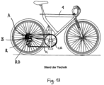
- FIG 13 shows an example of a bicycle with a bicycle drive known from the prior art.
- the bicycle drive comprises a front sprocket CR, a rear sprocket set R and a chain K, which can be moved from one sprocket to the next by means of the rear derailleur RD.
- the directional information right/left and front/back used in the following refers to a bicycle in the direction of travel.
- the bicycle frame 1 has left and right rear dropouts between which the rear wheel is mounted.
- the rear wheel rotates together with the sprocket set R about the rear wheel axis A.
- Axial refers to the rear wheel axis A or the axis of rotation A of the multiple sprocket arrangement R.
- the largest sprocket is axially further inwards than the smaller sprockets.
- the teeth are arranged radially on the outside of the pinions.
- the outside diameter of a sprocket is the radially outer end, the inside diameter is the radially inner end of the sprocket.
- the RD rear derailleur shown here is conventionally attached to the right dropout of the frame with a derailleur hanger.
- the known rear derailleur RD is spaced from the rear wheel axle A and is not mounted coaxially with it.
- the derailleur RD rotates about the B axis, which is spaced from the A axis.
- the pivot mechanism of the rear derailleur is designed as an inclined parallelogram.
- figure 1 shows a perspective view of the rear derailleur 10 according to the invention mounted coaxially on the rear wheel axle 6.
- the rear wheel and the sprocket set are not shown.
- the rear wheel hub 3 arranged between the two dropouts of the frame 1 and the rear derailleur 10 surrounding the right dropout can be seen.
- the base element 20 is mounted on the frame 1 coaxially with the axis A by means of the adapter 60 .
- figure 2 shows a section along the axis A of the in figure 1 illustrated rear derailleur 10 in the rear view.
- the geometric axis A extends along the Rear wheel axle 6.
- the base element 20 is attached to the right dropout by means of the adapter 60 .
- the adapter 60 passes through the right-hand frame opening 2b.
- the quick-release axle 7 is inserted into the left-hand frame opening 2a and screwed to the adapter 60.
- the adapter 60 also serves as a counter for the thru-axle 7. When the thru-axle 7 is tightened, it screws further into the adapter 60 and clamps against the frame 1.
- FIG 3 shows a side view of the rear derailleur 10 according to the invention mounted on the frame 1 figure 2 .
- the Figures 1 to 3 each show the entire rear derailleur 10 with the base element 20, the pivoting mechanism 30, the movable element 40 and the chain guide arrangement 50.
- a cable deflection 11 is arranged on the base element 20, here in the form of a cable deflection roller rotatably mounted at the connection point 29c.
- the base element 20 is mounted on the frame 1 coaxially with the rear wheel axle A at its first, upper connection end.
- two arms of the base element 20 spaced apart from one another in the axial direction encompass the dropout of the frame 1, so that one arm is arranged on the inside of the frame 1 and the other arm on the outside of the frame 1.
- the base element 20 is pre-assembled on the frame 1 with the adapter 60 . Furthermore, the base element 20 is coupled to the pivoting mechanism 30 at its second, lower connection end.
- the swivel mechanism 30 is designed as a four-bar parallelogram linkage with an inner swivel arm 35, an outer swivel arm 36 and four swivel axes 31, 32, 33, 34.
- the four pivot axes 31, 32, 33, 34 each run in planes that intersect the axis A at right angles. In other words, the pivot axes 31, 32, 33, 34 lie in planes that extend parallel to the pinion planes, not shown here (cf. Figure 11 to 13 ).
- the first and second pivot axis 31, 32 connects the pivot mechanism 30 to the base element 20.
- the third and fourth pivot axis 33, 34 connects the pivot mechanism 30 to the movable element 40.
- Both the base element 20 and the movable element 40 each have two receptacles for the swivel axes.
- the longitudinal axes L1, L2 of the housings on the base element 20 and the longitudinal axes of the housings on the mobile element 40 are like the pivot axes 31, 32, 33, 34 itself aligned orthogonally to the rear wheel axle 6 or the axis A (cf. Figures 4 to 9 ).
- the chain guide arrangement 50 is rotatably connected to the movable element 40 about the axis P and is prestressed clockwise (to the rear), so that a chain (not shown here) running through the chain guide 50 in an S-shape is tensioned.
- the chain guide arrangement 50 comprises an upper and a lower chain guide roller 51, 52, which are each rotatably mounted between two cage halves 57a, 57b.
- the upper chain guide roller 51 is arranged at an upper distance from the axis P so as to be rotatable about the upper axis of rotation 55 .
- the lower chain guide roller 56 is rotatably arranged at a lower distance from the P-axis around the lower pivot 56, with the upper chain guide roller 51 being arranged at a smaller distance from the P-axis than the lower chain guide roller 52 is.
- the movable element 40 has a locking element 42 which allows the prestressed chain guide arrangement 50 to be fixed in relation to the movable element 40 . In this way, the rear derailleur 20 can be assembled without the chain guide assembly 50 snapping backwards due to the preload.
- the chain guide assembly 50 When shifting to a smaller sprocket, the chain guide assembly 50 rotates backwards about the axis of rotation P of the movable member 40 in the clockwise direction. Conversely, when shifting to a next larger sprocket, the chain guide assembly 50 rotates forward about the axis of rotation P counterclockwise. Due to the rotary movement about the axis P, the upper chain guide roller 51 is moved radially towards or away from the sprockets. The chain guide arrangement 50 is moved in the axial direction in that the pivot arms 35, 36 are pivoted about the pivot axes 31, 32, 33, 34. Depending on the direction of shifting, the upper chain guide roller 51 moves inwards or outwards in the axial direction together with the entire chain guide arrangement 50 .
- FIG 4 and 5 each show perspective partial sections of the base element 20 mounted on the frame 1 with the aid of the adapter 60 and parts of the hub arrangement.
- the first arm 22a and the second arm 22b are positioned on one side of the frame 1, respectively.
- the hub guide 27 is designed as a collar with guide surfaces running towards one another. In its final position, the hub end cap 4 lies radially against the hub guide 27 . In the axial direction, the hub end cap 4 abuts against the axial hub stop surface 26 on the inside of the base element 20.
- the hub end cap 4 is shown in section.
- FIG 5 shows a section through the base element 20 with the two arms 22a, 22b surrounding the adapter 60.
- the adapter 60 consists of the bolt 61 and the nut 66.
- the bolt 61 is screwed into the nut 66 so that the bolt head 62 and the nut 66 are clamped to the frame 1.
- the adapter 60 can be fixed relative to the frame 1 in this way.
- the base element 20 is centered on the adapter 60 .
- the base element 20 is clamped in a rotationally fixed manner between the hub end cap 4 and the adapter 60 .
- the base element 20 rests in the axial direction only on the hub end cap 4 and on the adapter 60 .
- the base element 20 is indirectly mounted on the frame 1 via the adapter 60 .
- the base element 20 and thus the entire rear derailleur 10 is referenced on the hub 4 - and not on the frame 1 as is usual.
- FIG 6 shows the enlarged partial section of the base element 20 mounted on the frame 1 with the adapter 60 figure 5 .
- Bolt head 62 and nut 66 are sized larger than frame opening 2b.
- the nut 66 has a knurled surface 69 in order to additionally produce a positive connection to the frame 1 and to counteract a forward twisting of the rear derailleur 10 (counterclockwise).
- the bolt body 63 has a contact area 63a which bears against the frame opening 2b with little play and a compensating area 63b which has more play compared to the frame opening 2b.
- the balancing area 63b allows the adapter 60 to align along the axis A in the frame opening 2b.
- the bolt 61 has play in the frame opening 2b and can tilt slightly therein if the frame opening is not exactly aligned with the axis A.
- FIG 7 shows the arrangement figure 6 with cut adapter 60.
- the adapter 60 has two tasks: 1) The clamp on the frame 1 is through the Screw connection between bolt 61 and nut 66 made. Alternatively, the nut could also be arranged on the outside and the bolt on the inside. It is important that the adapter 60 can be fixed relative to the frame 1 and can be adapted to it in the axial direction. With a thinner frame, the screw connection is tightened further than with a thicker frame. 2) The adapter 60 can only be twisted to a limited extent in relation to the base element 20 in the clockwise direction and thus represents an anti-twist device.
- the external thread 64 and the internal thread 65 of the bolt 61 are arranged in different areas along the bolt 61 in order to be able to absorb forces better.
- the quick-release axle 7 is screwed into the internal thread 65 and pulls the adapter 60, in particular the bolt head 62, against the outside of the frame 1.
- a washer is arranged between the bolt head 62 and the frame 1.
- FIG figure 8 an exploded view of the unassembled base member 20 and adapter 60.
- FIG figure 7 the internal thread 67 of the nut 66 and the external thread 64 of the bolt 61, which together form the screw connection of the adapter 60, can be seen clearly.
- the bolt could also be screwed directly into a thread in the frame opening. But then frame tolerances would have a direct effect on the rear derailleur, which should be avoided.
- the bolt foot 63c matched to the first centering opening 23a and the bolt head 62 matched to the second centering opening 23b can be seen.
- the stop surface 63d of the bolt 61 interacts with the outside of the first arm 22a of the base element 20, which is turned away here (cf. Figure 9a ).
- Figure 9a and 9b show a perspective outside and inside view of the base element 20 with the first and second centering opening 23a, 23b.
- the first Centering opening 23a is matched to the outside diameter of bolt foot 63c of bolt 61 .
- the second centering opening 23b is matched to the outside diameter of the bolt head 61 .
- the adapter stop surface 25 which interacts with the stop surface 63d of the bolt 61 can be seen on the outside of the first arm 22a.
- the hub stop surface 26 is arranged on the opposite inner side of the first arm 22a. In the ready-to-drive condition, the bolt 61 is clamped with the bolt stop surface 63d against the outside and the hub end cap 4 is clamped against the inside of the base element 20 .
- connection point 29c for a cable deflection 11 is located at the lower connection end of the base element 20.
- first receptacle 29a for the first pivot axis 31 and the second receptacle 29b for the second pivot axis 32 of the pivot mechanism are located at the lower connection end of the base element 20 30.
- the longitudinal axes L1, L2 of the first and second receptacles 29a, 29b extend in planes which intersect the rear wheel axis A at right angles, respectively.
- the four pivot axes 31, 32, 33, 34 of the parallelogram four-bar linkage 30 are therefore aligned orthogonally to the common pinion axis A, independently of the selected relative position of the rear derailleur 10.
- figure 10 shows a partial section through the second embodiment of the rear derailleur 10 according to the invention with an adjustment aid.
- the section runs through the movable element 40 and the chain guide assembly 50.
- the adjustment aid is in the form of the locking element 42 which engages in the locking opening 58 in the outer cage half 57b.
- the chain guide arrangement 50 which is prestressed in the CW direction, is fixed in a predetermined rotational position relative to the movable element 40 by means of the adjustment aid.
- the predetermined rotational or angular position defines the upper chain guide roller 51 at an ideal distance from a reference sprocket of the sprocket set, not shown here.
- To adjust the rear derailleur 10 this is locked using the adjustment aid. After adjustment, the lock is released so that the chain guide assembly 50 can rotate relative to the movable member 40 .
- figure 11 and 12 show third exemplary embodiments of the rear derailleur 10 according to the invention with limit stops 59a and 59b, which make it possible to dispense with the usual limit screws 70 (limit screws).
- limit screws 70 limit screws
- the limit screws are 70 in figure 12 still shown.
- the rear derailleur 10 in figure 11 is aligned with the largest sprocket R12 of the sprocket pack R. This position represents the inner maximum position.
- the rear derailleur 10 should not move further inwards in the axial direction.
- the first limit stop 59a is arranged on the chain guide arrangement 50, in particular on the inside of the outer cage half 57b.
- the first limit stop 59a is designed to cooperate with the largest sprocket R12.
- the inner limit stop 59a projects beyond the cage 57b in the area of the P axis and, in the inner maximum position, abuts against the outside of the Pinion R12.
- the chain guide arrangement 50 can then not be moved any further inwards in the axial direction in relation to the largest sprocket R12.
- the outer cage half 57b of the chain guide arrangement 50 extends in the radial direction into an area of the largest sprocket R12 which is located within the radial outer diameter of the largest sprocket R12. In the axial direction, the outer cage half 57b extends in the inner maximum position of the rear derailleur 10 between the largest sprocket R12 and its adjacent next smaller sprocket R11. In the inner maximum position of the rear derailleur 10, a chain (not shown here) is in engagement with the largest sprocket R12.
- the outer cage half 57b or the inner limit stop 59a abuts against the largest sprocket R12 and thus limits the movement of the rear derailleur 10.
- the inner limit stop 59a is here in one piece of the outer cage half 57b. Multi-part designs of cage and limit stop are also conceivable.
- the movable element can also be designed in such a way that it acts as an inner limit stop in the intended, inner maximum position of the rear derailleur.
- the inner limit stop interacts with the sprocket set, in particular a sprocket or another suitable element assigned to the sprocket set, for example a chain guard.
- the rear derailleur 10 is aligned with the smallest sprocket R1 of the sprocket pack R.
- the chain guide assembly 50 is rotated much further rearward (CCW).
- the upper chain guide roller 51 is about the same distance from the pinion R1 in the radial direction, as in FIG figure 12 from the pinion R12.
- the position shown represents the outer maximum position of the rear derailleur 10.
- the rear derailleur 10 should not move further outwards in the axial direction.
- the second limit stop 59b is arranged on the chain guide arrangement 50, in particular on the outside of the outer cage half 57b.
- the second limit stop 59a is designed in such a way that it can be connected to the base element 20 works together.
- the outside of the outer cage half 57b in the area of the upper chain guide roller 51 acts as a second limit stop 59b.
- the second limit stop 59b abuts against the inside of the base element 20.
- the inside of the base element 20 is at the same time the inside of the first arm 22a.
- the chain guide arrangement 50 can then no longer be moved outwards in the axial direction relative to the base element 20 .
- the advantage of the limiting stops 59a, 59b is that these fixed stops no longer have to be adjusted, but are already matched to the sprocket set R.
- the limiting screws 70 for setting the stops are no longer necessary.
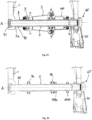
- figure 14 shows a sectional representation of a fourth exemplary embodiment along the axis A in rear view.
- the frame 1 the quick-release axle 70, the right-hand hub end cap 4 and selected parts of the rear derailleur are shown in this illustration. All visible parts are shown in section.
- the base element 20 is attached to the right dropout by means of the adapter 60 .
- the bolt 61 extends through the right-hand frame opening 2b and is screwed to the nut 66 .
- the first end 71 of the quick-release axle 70 is inserted into the left-hand frame opening 2a and its second end 72 is screwed into the bolt 61 of the adapter 60 .
- the adapter 60 or the bolt 61 also serves as a counter for the quick-release axle 70. When the quick-release axle 70 is tightened, it screws further into the bolt 61 and clamps it against the frame 1.
- the outer diameter 74 of the quick-release axle 70 is dimensioned smaller than the frame opening 2a. The gap is compensated with a bushing 71a.
- the first axle end 71 has a head with a larger diameter than the frame opening 2a, and cannot slip through the frame opening 2a.
- the head diameter decreases continuously from the first end 71 to the body or shaft of the thru axle 70 down to the outer diameter 74.
- the transition is at a 45 degree angle. Other angles, in particular 90 degrees, are also conceivable.
- the inner arm 22a of the base member 20 is fixed between the right hub end cap 4 and the bolt 61 in the axial direction.
- the inner arm 22a of the base element 20 is positioned in the radial direction on the centering area of the bolt 61 (cf. details in figure 7 and 8th ) and the outer arm 22b centered on the bolt head 62.
- the quick-release axle 70 shown has an outer diameter 74 of 12 mm and an inner diameter 75 of 7 mm. This results in a thru-axle wall thickness of 2.5 mm.
- the exemplary embodiment of the thru axle 70 in figure 14 essentially corresponds to the previous figures, but is again shown here directly according to a quick-release axle 80 Figure 15a with an enlarged outer diameter 84 and a different centering.
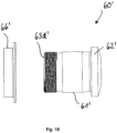
- Figure 15a shows a sectional view of a fifth exemplary embodiment, which differs from the previous embodiment in several respects due to the quick-release axle 80 with an enlarged outer diameter 84 .
- the through axle 80 shown has an outer diameter 84 of 15 mm and a first inner diameter 85 of 12 mm. This leads to a first wall thickness W85 of 1.5 mm. All parts shown are shown in section.
- the frame 1 with its frame openings 2a and 2b, the hub arrangement with the hub end cap 4, which is only partially shown here, and the base element 20 of the rear derailleur are unchanged. Only the adapter 60' has to be adapted to the enlarged outside diameter 84 of the through-axle 80. In order to be able to accommodate the quick-release axle 80, the diameter of the internal thread 65 ⁇ of the bolt 61' is adapted to its external diameter 84. In addition, the centering area (cf. centering area 63c of the previous embodiments) on the bolt 61' is omitted. This results in the base member 20 directly contacting the outer peripheral surface of the thru-axle 80 .
- the inner arm 22a of the base member 20 centers directly on the thru-axle 80, rather than on the adapter 60 as in the previous examples.
- the outer arm 22b of the base member continues to center on the outer periphery of the bolt head 62'.
- the referencing of the base element 20 in the axial direction and in the radial direction takes place independently of the frame 1.
- the base element 20 is between the hub end cap 4 and the adapter 60 ⁇ , in particular the stop surface 63d ⁇ of the bolt 61' (see figure 19 ), fixed.
- the inner arm 22a of the base element 20 is centered directly on the quick-release axle 80 and the outer arm 22b on the adapter 60', in particular on the bolt head 62'.
- the extensive independence from frame tolerances allows precise alignment of the rear derailleur even if the two frame openings 2a and 2b are not exactly aligned.
- the transition between the head at the first end 81 of the thru-axle 80 to the thru-axle body with the outer diameter 84 is right-angled here.
- the outside diameter 84 of the through axle 80 corresponds approximately to the frame opening 2a.
- the quick-release axle 80 is guided through the opening 2a with less play.
- the socket 91a has a 45 degree angle and is used to center the quick-release axle 80 in the frame opening 2a. This socket could also be formed at a different angle.
- Figure 15b a perspective external view of the sectional view Figure 15a .
- the hub end cap 4 abuts axially against the hub stop surface 26 of the base member 20 .
- FIG 16 1 is an enlarged detailed view of the right dropout of the frame 1 from FIG Figure 15b shown.
- the second end 82 of the quick-release axle 80 is screwed into the internal thread 65' of the bolt 61' of the adapter 60'.
- the inner arm 22a of the base element 20 rests with its first centering opening 23a in the radial direction directly on the outer circumference of the wheel spindle 80 .
- the inner arm 22a is fixed between the hub end cap 4 and the stop surface 63d ⁇ of the bolt 61'.
- the nut 66' essentially corresponds to the previous exemplary embodiments.
- FIG 17 corresponds to the view figure 16 , with the hub end cap and adapter nut omitted for clarity.
- the bolt 61' strikes in the axial direction with its stop face 63d' against the counter stop face 25 of the inner arm 22a.
- the outer arm 22b of the base member 20 remains centered with its second centering opening 23b on the outer circumference of the bolt head 62'.
- figure 18 shows the arrangement figure 17 without the bolt.
- the centering of the base element 20 on the quick-release axle 80 is particularly clear here.
- the second end 82 of the quick-release axle 20 passes through the inner arm 22a of the base element 20.
- the external thread 83 of the quick-release axle 80 lies in the assembled state between the first and the second arm 22a, 22b of the base element 20.
- the surface 87 of the thru-axle 80 is processed at least in the contact area between the base element 20 and the thru-axle 80.
- This centering surface 87 is finely turned, ground and/or coated, for example. Due to the complex processing, the centering surface 87 is kept as narrow as possible. However, the centering surface 87 must be at least as wide as the first centering opening 23a of the first arm 22a of the base element 20 .
- the centering surface 87 of the full-floating axle 80 extends at least into the area of the bolt 61 ′ in the assembled state, so that the bolt foot comes to rest on the centering surface 87 .
- This design permits precise centering of the bolt 61' on the quick-release axle 80. Centering by screwing the external thread 83 of the quick-release axle 80 into the internal thread 65' of the bolt 61' alone is not precise enough due to the thread play. The centering surface 87 takes out the play between the bolt 61' and the quick-release axle 80. A particularly rigid connection between the quick-release axle 80 and the bolt 61' is thus possible.
- the centering surface 87 should have a minimum width so that tolerances depending on the screw-in depth, depending on the hub arrangement and frame width, can be compensated and the base element 20 always comes to rest on the surface 87 .
- An axial width of the centering surface 87 of about 2.5 mm (or more) is sufficiently wide and can be manufactured relatively quickly and inexpensively.
- Another centering surface could be attached to the extreme second end of the thru-axle, which also cooperates with the bolt and becomes a even more rigid connection.
- the outer surface of particularly high-quality thru-axles could also be completely reworked.
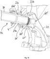
- FIG 19 shows an enlarged exploded view in the uncut rear view of the adapter 60', consisting of the bolt 61' and the nut 66'.
- the adapter 60' essentially corresponds to the adapter 60 of the previous exemplary embodiment in FIGS Figures 1 to 12 , which is why only the differences are discussed here.
- the inner thread which has been enlarged in diameter and adapted to the 15 mm thru-axle 80, is not visible in the rear view.
- the stop 63d ⁇ forms the inner axial end of the bolt 61 ⁇ .
- the other external dimensions of the bolt 61' are unchanged and matched to the base element 20.
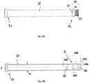
- a quick-release axle 80 according to the fifth exemplary embodiment is shown in an uncut rear view in FIG Figure 20a and in a sectional view along the axis A in Figure 20b shown.
- the quick-release axle 80 has an outside diameter 84 of 15 mm.
- the overall axial width from the first end 81 to the second end 82 varies depending on the hub standard used and the general conditions. Typical hub widths from left to right hub end cap are 142 to 148 mm.
- the external thread 83 and the centering surface 87 are arranged in the area of the second end 82 of the quick-release axle.
- the centering surface 87 is axially further inward than the external thread 83.
- the centering surface 87 begins at a distance 88 of about 13.5 mm and ends at a distance 88 of about 16 mm from the second quick-release axle end 82.
- the centering surface 87 has an axial width B87 of about 2.5mm.
- the axial width B83 of the external thread 83 measures approximately 10 mm.
- the quick-release axle 80 has an outer diameter 84 of 15 mm. Only the first end 81 has a larger head diameter. A first inner diameter 85 of the through axle 80 is 12 mm. This results in a first wall thickness W85 of about 1.5 mm. The first wall thickness W85 extends over a large part of the axial width of the through-axle 80. In the area of the second end 82 of the through-axle, it has a second inner diameter 86, which is approximately 10 mm. The second inside diameter 86 is smaller than the first inside diameter 85. The second inside diameter 86 results in a second wall thickness W86, which is greater than the first wall thickness is W85. In the exemplary embodiment shown, the second wall thickness W86 is approximately 2.4 mm.
- the second inner diameter 86 or the increased second wall thickness W86 is arranged precisely in the areas of the through axle 80 that are heavily loaded. In particular in the area of the external thread 83.
- the area of the centering surface 87 also has an increased wall thickness W86, because here the base element 20 rests on the quick-release axle 80 and correspondingly larger forces act.
- the transition between the first and second inner diameters W85, W86 is continuous.
- the second inner diameter 86 extends from the outermost second floating axle end 82 in the axial direction over a width B86 of approximately 18 mm.
- the figure 21 shows a sectional view of a rear wheel axle arrangement with a quick-release axle 80 according to the fifth exemplary embodiment. All parts are shown in section.
- the quick-release axle 80 passes through the frame opening 2a, the hub arrangement and the driver 100 and is screwed into the rear derailleur, in particular the adapter 60'.
- the rear derailleur (only partially shown here) is attached to the right-hand dropout of the frame 1 via the base element 20 and the adapter 60'.
- the hub arrangement is fastened to the frame 1 with the quick-release axle 80 .
- the base element 20 is braced against the hub arrangement, in particular the right-hand hub end cap 4, in the axial direction.
- the hub assembly includes, among other things, the left hub end cap 8, the hub bearing 9, the hub shell 3, the hub axle 5 and the right hub end cap 4.
- FIG 22 shows selected parts of the rear wheel axle assembly figure 21 .
- the driver and most parts of the hub assembly have been removed for clarity. Only the hub axle 5 and the hub bearing 9, consisting of the hub bearings 9a, 9b of the hub arrangement designed as roller bearings, are shown.
- the quick-release axle 80 is inserted into the hub axle 5 with little play.
- the hub bearings 9a, 9b and the driver bearings 109a, 109b are fitted onto the hub axle 5. All parts are shown in section.
- FIG 23 shows the sectional view of the rear wheel axle assembly figure 22 without the bearings.
- the quick-release axle 80 with an outer diameter 84 of 15 mm is inserted into the hub axle 5 with little play.
- the inner diameter d5 of the hub axle 5 is slightly more than 15 mm.
- the outside diameter D5 of the hub axle 5 is about 17 mm.
- the wall thickness W85 of the thru-axle 80 is greater than the wall thickness W5 of the hub axle 5.
- the wall thickness W85 of the thru-axle 80 is about 1.5 mm and thus 1.5 times that of the hub axle 5. This leads to a relatively balanced ratio of the area moments of inertia .
- Figure 24a shows a partial section through selected parts of a rear wheel axle arrangement with a quick-release axle 90 according to the sixth exemplary embodiment. With the exception of the quick-release axle 90, all parts are shown in section.
- Figure 24b shows the partial section Figure 24a in an external perspective view.
- the quick-release axle 90 passes through the left frame opening 2a, the hub end caps 8, 4 and the hub axle 5 with little play.
- the second quick-release axle end 92 is screwed with the external thread 93 into the adapter 60' of the rear derailleur.
- the first outer diameter 94a of the quick-release axle 90 is slightly smaller than the inner diameter of the hub axle 5.
- the quick-release axle 90 has the first outer diameter 94a in the areas with increased loads. These are in particular the quick-release axle ends 91, 92 and the areas of the bearings 9a, 9b, 109a, 109b.
- the remaining areas of the wheel spindle 90 have a second, reduced outer diameter 94b.
- the quick-release axle 90 according to the sixth embodiment is shown in an uncut rear view in FIG Figure 25a and in a sectional view along the axis A in Figure 25b shown.
- the quick-release axle 90 differs from the quick-release axle 80 primarily in that it has a reduced wall thickness W94b in large areas to save weight.
- the through axle 90 has a first outer diameter 94a of 15 mm and a first inner diameter 95 of 12 mm.
- the first outer diameter 94a of 15mm has been reduced to a second outer diameter 94b of 14mm.
- the first inner diameter 95 remains unchanged. This results in a first wall thickness W94a of 1.5 mm in the area of the first outer diameter 94a and a second, reduced wall thickness W94b of 1 mm in the area of the reduced outer diameter 94b.
- the quick-release axle 90 has the larger outside diameter 94a and the greater wall thickness W94b only in the axial areas that are subject to a greater load.
- the through axle 90 has a second smaller inside diameter 96 in the region of the second end 92, which is approximately 10 mm.
- a third wall thickness W96 results from the second inner diameter 96, which is greater than the first and the second wall thickness W94a, W94b.
- the second inner diameter 96 or the increased second wall thickness W96 is arranged in the heavily loaded area of the external thread 93 and the centering surface 97 .
- first end 91 with an enlarged head diameter, right-angled transition to the first outer diameter 94a, first inner diameter 95 with the resulting wall thickness W94a in the areas subjected to greater loads, in between the reduced outer diameter 94b with the resulting reduced wall thickness W94b, transition from the reduced outer diameter 94b to the second inner diameter 96 with the resulting wall thickness W96, centering surface 97, external thread 96 and second quick-release axle end 92.
- the reduced outer diameter 94b can be produced particularly easily by turning off the excess material on the outside of the quick-release axle 90.
- a reduced wall thickness could also be realized by a third, enlarged inner diameter. Material is removed or saved on the inside of the thru-axle and not on the outside. The weight saving effect would be the same.
- the quick-release axles 80, 90 with an increased outer diameter of 15 mm have a greatly increased area moment of inertia compared to the quick-release axles 70 with an outer diameter of 12 mm, despite a lower wall thickness of 1 mm to 2 mm. Stiffness is increased and/or weight reduced.
- the through axle 80 according to the fifth exemplary embodiment can achieve an approximately 30% higher area moment of inertia of the overall system and at the same time a somewhat 21% lower weight.
- Another exemplary embodiment, not shown here, which could be used specifically for e-bikes, is a thru-axle with an outer diameter of 15 mm and an inner diameter of 11 mm.
- the area moment of inertia is reduced somewhat, but the weight is significantly saved.
- the more even distribution of the area moment of inertia on the thru axle and hub axle leads to an overall more stable axle arrangement, because the maximum stresses on the outer skin of the hub axle are lower.
- both the rigidity and the weight can be further influenced.
- Preferred materials for the thru-axle are aluminium, titanium or steel.
- the modular system allows a simple and inexpensive exchange of the thru-axle 70, 80, 90.
- a stiffer or lighter thru-axle can be selected. Only the adapter 60, 60' has to be adapted to the selected thru-axle 70, 80, 90.
- the hub arrangement, the driver 100, the base element 20 and the remaining parts of the rear derailleur can be used unchanged and are not affected by changing the thru-axle.
- the wall thicknesses of the hub and quick-release axles mentioned in the exemplary embodiments described above are designed for production from aluminum.
- the statements made on the area moment of inertia remain independent of the material. As long as the same material is used for the thru axle and the hub axle, the wall thickness ratios mentioned can be maintained.
- the wall thicknesses can be adjusted according to the maximum stresses.
- a thru-axle could be made from titanium and a hub axle from aluminum. Then the thru-axle could be designed with thinner walls in accordance with the allowable yield points.
Landscapes
- Engineering & Computer Science (AREA)
- Mechanical Engineering (AREA)
- Chemical & Material Sciences (AREA)
- Combustion & Propulsion (AREA)
- Transportation (AREA)
- Axle Suspensions And Sidecars For Cycles (AREA)
- Transmissions By Endless Flexible Members (AREA)
- Devices For Conveying Motion By Means Of Endless Flexible Members (AREA)
- Automatic Cycles, And Cycles In General (AREA)
- Input Circuits Of Receivers And Coupling Of Receivers And Audio Equipment (AREA)
- Support Of Aerials (AREA)
- Steering-Linkage Mechanisms And Four-Wheel Steering (AREA)
Applications Claiming Priority (3)
| Application Number | Priority Date | Filing Date | Title |
|---|---|---|---|
| DE102017002629 | 2017-03-20 | ||
| DE102018001253.1A DE102018001253A1 (de) | 2017-03-20 | 2018-02-16 | Hinteres Schaltwerk zur koaxialen Montage |
| EP18000255.2A EP3388324B1 (fr) | 2017-03-20 | 2018-03-14 | Derailleur arrière destiné au montage coaxial |
Related Parent Applications (2)
| Application Number | Title | Priority Date | Filing Date |
|---|---|---|---|
| EP18000255.2A Division EP3388324B1 (fr) | 2017-03-20 | 2018-03-14 | Derailleur arrière destiné au montage coaxial |
| EP18000255.2A Division-Into EP3388324B1 (fr) | 2017-03-20 | 2018-03-14 | Derailleur arrière destiné au montage coaxial |
Publications (2)
| Publication Number | Publication Date |
|---|---|
| EP4219281A2 true EP4219281A2 (fr) | 2023-08-02 |
| EP4219281A3 EP4219281A3 (fr) | 2023-11-15 |
Family
ID=63372508
Family Applications (2)
| Application Number | Title | Priority Date | Filing Date |
|---|---|---|---|
| EP18000255.2A Active EP3388324B1 (fr) | 2017-03-20 | 2018-03-14 | Derailleur arrière destiné au montage coaxial |
| EP23020162.6A Pending EP4219281A3 (fr) | 2017-03-20 | 2018-03-14 | Dérailleur arrière pour montage coaxial |
Family Applications Before (1)
| Application Number | Title | Priority Date | Filing Date |
|---|---|---|---|
| EP18000255.2A Active EP3388324B1 (fr) | 2017-03-20 | 2018-03-14 | Derailleur arrière destiné au montage coaxial |
Country Status (7)
| Country | Link |
|---|---|
| US (4) | US10870464B2 (fr) |
| EP (2) | EP3388324B1 (fr) |
| CN (2) | CN113173224B (fr) |
| DE (1) | DE102018001253A1 (fr) |
| ES (1) | ES2953658T3 (fr) |
| PL (1) | PL3388324T3 (fr) |
| TW (2) | TWI765982B (fr) |
Families Citing this family (41)
| Publication number | Priority date | Publication date | Assignee | Title |
|---|---|---|---|---|
| DE102018001253A1 (de) * | 2017-03-20 | 2018-09-20 | Sram Deutschland Gmbh | Hinteres Schaltwerk zur koaxialen Montage |
| US10464634B2 (en) * | 2017-07-12 | 2019-11-05 | Shimano Inc. | Bicycle rear derailleur |
| US10766301B2 (en) * | 2017-12-14 | 2020-09-08 | Shimano Inc. | Rear wheel fixing mechanism for a bicycle |
| US10981626B2 (en) * | 2018-03-20 | 2021-04-20 | Sram Deutschland Gmbh | Drive arrangement for a bicycle |
| TWM562816U (zh) * | 2018-04-03 | 2018-07-01 | 彥豪金屬工業股份有限公司 | 變速器總成 |
| DE102018206104A1 (de) | 2018-04-20 | 2019-10-24 | Sram Deutschland Gmbh | Schaltauge zur Montage eines hinteren Schaltwerks an einem Fahrradrahmen und Set von Komponenten zur wahlweisen Montage alternativer hinterer Schaltwerke an dem Fahrradrahmen |
| DE102018214218A1 (de) * | 2018-08-22 | 2020-02-27 | Sram Deutschland Gmbh | Hinterrad-Kettenschaltwerk mit exzentrischer Seilzug-Umlenkrollenanordung mit Übersetzungsverhältnis |
| DE102018222834A1 (de) * | 2018-12-21 | 2020-06-25 | Sram Deutschland Gmbh | Halterungselement und Fahrrad mit einem Halterungselement |
| TWI730290B (zh) * | 2019-02-13 | 2021-06-11 | 彥豪金屬工業股份有限公司 | 自行車後變速器的固定組件 |
| US11498643B2 (en) * | 2019-02-26 | 2022-11-15 | Shimano Inc. | Bicycle electric derailleur |
| DE102020201229A1 (de) * | 2019-03-22 | 2020-09-24 | Sram Deutschland Gmbh | Koaxiale Schaltwerksanbindung |
| EP3712052A1 (fr) | 2019-03-22 | 2020-09-23 | SRAM Deutschland GmbH | Raccordement coaxial de monte-et-baisse |
| PL3730394T3 (pl) * | 2019-04-25 | 2024-03-04 | Sram Deutschland Gmbh | Elektromechaniczna tylna przerzutka rowerowa do montażu współosiowego |
| DE102020000827A1 (de) | 2019-04-25 | 2020-10-29 | Sram Deutschland Gmbh | Elektromechanisches Schaltwerk zur koaxialen Montage |
| US11608139B2 (en) | 2019-05-13 | 2023-03-21 | Shimano Inc. | Bicycle rear derailleur |
| EP3782891B1 (fr) | 2019-08-23 | 2022-12-07 | SRAM Deutschland GmbH | Dérailleur de bicyclette pourvu d'affichage de réglage |
| DE102020210354A1 (de) | 2019-08-23 | 2021-02-25 | Sram Deutschland Gmbh | Fahrradschaltwerk mit einstellanzeige |
| US11511826B2 (en) * | 2019-12-09 | 2022-11-29 | Sram, Llc | Bicycle axle assembly including a power meter |
| DE102020132208A1 (de) * | 2019-12-18 | 2021-06-24 | Sram Deutschland Gmbh | Fahrrad-Schaltwerk und Anbindung eines Schaltwerks an einem Fahrrad-Rahmen |
| EP3838731B1 (fr) * | 2019-12-18 | 2024-05-15 | SRAM Deutschland GmbH | Dérailleur de bicyclette et raccordement d'un dérailleur à un cadre de bicyclette |
| TWI742700B (zh) * | 2020-05-29 | 2021-10-11 | 彥豪金屬工業股份有限公司 | 自行車後變速器 |
| EP3964437A1 (fr) * | 2020-09-03 | 2022-03-09 | SRAM Deutschland GmbH | Derailleur arriere électromécanique pour montage coaxial pourvu de dispositif de blocage |
| DE102021131414A1 (de) | 2020-12-03 | 2022-06-09 | Sram Deutschland Gmbh | Hinteres Schaltwerk zur koaxialen Anbindung an einem Fahrrad-Rahmen |
| EP4008622B1 (fr) | 2020-12-03 | 2024-09-04 | SRAM Deutschland GmbH | Mécanisme de commutation arrière destiné à la liaison coaxiale à un cadre de bicyclette |
| TW202227319A (zh) | 2020-12-31 | 2022-07-16 | 日商島野股份有限公司 | 托架裝置 |
| TW202227320A (zh) | 2020-12-31 | 2022-07-16 | 日商島野股份有限公司 | 後撥鏈器 |
| US12024264B2 (en) | 2021-03-26 | 2024-07-02 | Sram Deutschland Gmbh | Bicycle derailleur pulley |
| DE102022103284A1 (de) | 2021-03-26 | 2022-09-29 | Sram Deutschland Gmbh | Kettenführungsrolle für Fahrrad-Schaltwerk sowie Fahrrad-Schaltwerk und Fahrrad-Antriebsstrang |
| TW202246122A (zh) | 2021-05-24 | 2022-12-01 | 新加坡商島野(新)私人有限公司 | 人力驅動車之後變速器 |
| DE102022115599A1 (de) | 2021-06-29 | 2022-12-29 | Sram Deutschland Gmbh | Modulares Fahrrad-Schaltwerk |
| CN218141972U (zh) | 2021-06-29 | 2022-12-27 | Sram德国有限公司 | 自行车换挡机构及用于自行车换挡机构的马达传动单元 |
| JP2023028813A (ja) | 2021-08-20 | 2023-03-03 | 株式会社シマノ | 人力駆動車用のリアディレイラ |
| TWI800929B (zh) * | 2021-09-27 | 2023-05-01 | 彥豪金屬工業股份有限公司 | 自行車後變速器 |
| JP2023057891A (ja) | 2021-10-12 | 2023-04-24 | 株式会社シマノ | 人力駆動車用のリアディレイラ |
| JP2023057889A (ja) | 2021-10-12 | 2023-04-24 | 株式会社シマノ | 人力駆動車用のリアディレイラ |
| JP2023057890A (ja) | 2021-10-12 | 2023-04-24 | 株式会社シマノ | 人力駆動車用のリアディレイラ |
| US20230182860A1 (en) * | 2021-12-09 | 2023-06-15 | Sram, Llc | Bicycle derailleur |
| US12059924B1 (en) | 2023-09-05 | 2024-08-13 | Red Star Holdings, Llc | Bicycle hub system, method and device including a front hub locking mechanism |
| US12059923B1 (en) | 2023-09-05 | 2024-08-13 | Red Star Holdings, Llc | Bicycle hub system, method and device including a rear hub locking mechanism |
| US12059922B1 (en) | 2023-09-05 | 2024-08-13 | Red Star Holdings, Llc | Bicycle hub system, method and device including an interchangeable hub locking mechanism |
| US11975802B1 (en) | 2023-09-05 | 2024-05-07 | Red Star Holdings, Llc | Bicycle hub system, method and device including an interchangeable rear hub with a direct mount derailleur |
Citations (3)
| Publication number | Priority date | Publication date | Assignee | Title |
|---|---|---|---|---|
| EP0875444A1 (fr) | 1997-04-30 | 1998-11-04 | Shimano Inc. | Dérailleur démontable rapide |
| EP1342658A1 (fr) | 2002-03-07 | 2003-09-10 | Shimano Inc. | Dérailleur arrière pour bicyclette |
| EP1764297A1 (fr) | 2004-09-01 | 2007-03-21 | Shimano Inc. | Dérailleur arrière pour bicyclette |
Family Cites Families (93)
| Publication number | Priority date | Publication date | Assignee | Title |
|---|---|---|---|---|
| US2108941A (en) * | 1936-04-14 | 1938-02-22 | Morgan Joseph Thomas | Change speed gear mechanism for cycles and the like |
| GB645791A (en) * | 1948-10-18 | 1950-11-08 | Frederick James William Markle | A foot-controlled derailleur change speed gear for cycles |
| GB660230A (en) * | 1949-02-10 | 1951-10-31 | Hercules Cycle And Motor Compa | Improvements in or relating to variable gear mechanism for cycles |
| US3111855A (en) * | 1960-05-31 | 1963-11-26 | Juy Lucien Charles Hippolyte | Change speed gear mechanism for bicycles and the like vehicles |
| US3184993A (en) * | 1963-12-11 | 1965-05-25 | Carl A Swenson | Derailleur guard |
| DE2314554C2 (de) * | 1973-03-23 | 1983-10-06 | Fichtel & Sachs Ag, 8720 Schweinfurt | Kettenschaltung mit Änderung des Anstellwinkels des Leitrades |
| FR2225327B1 (fr) * | 1973-04-16 | 1976-09-10 | Juy Lucien | |
| US3903751A (en) * | 1974-04-24 | 1975-09-09 | Beatrice Foods Co | Bicycle derailler with overload cable protection means |
| US4027542A (en) * | 1974-10-04 | 1977-06-07 | Shimano Industrial Company, Limited | Derailleur for bicycle |
| US3964330A (en) * | 1974-11-08 | 1976-06-22 | Maeda Industries, Ltd. | Chain guide connector device for use in bicycle derailleurs |
| US3979962A (en) * | 1974-12-12 | 1976-09-14 | Alex Kebsch | Bicycle gear shift derailleur |
| FR2314093A1 (fr) * | 1975-06-12 | 1977-01-07 | Huret Roger | Derailleur pour bicyclette |
| DE2654426A1 (de) * | 1975-12-02 | 1977-06-23 | Simplex Ets | Gangschaltung fuer fahrraeder oder aehnliche fahrzeuge |
| US4215872A (en) * | 1979-02-07 | 1980-08-05 | Clark Marion A | Positive shift derailleur mechanism |
| US4371064A (en) * | 1979-08-28 | 1983-02-01 | Shimano Industrial Company Limited | Drive and brake device for a bicycle |
| JPS56135391U (fr) * | 1980-03-14 | 1981-10-14 | ||
| FR2496587B1 (fr) * | 1980-12-23 | 1986-02-28 | Bridgestone Cycle Co | Changement de vitesses pour bicyclette |
| DE3113439A1 (de) * | 1981-04-03 | 1982-10-21 | Fichtel & Sachs Ag, 8720 Schweinfurt | Nabe fuer fahrraeder o.dgl. mit schnellspann-einrichtung zur befestigung der nabenachse |
| FR2508862A1 (fr) * | 1981-07-03 | 1983-01-07 | Simplex Ets | Dispositif de commande assurant des positions multiples preetablies et controlees, applicable en particulier aux changements de vitesse pour les cycles et vehicules similaires |
| JPH0671916B2 (ja) * | 1984-12-29 | 1994-09-14 | 島野工業株式会社 | 自転車用デイレ−ラ− |
| JPS63119196U (fr) * | 1987-01-28 | 1988-08-02 | ||
| JPS63195992U (fr) * | 1987-06-06 | 1988-12-16 | ||
| ES2037277T3 (es) * | 1987-07-24 | 1993-06-16 | Marelmo Di Marchigiano G., Ezzu L., Mogno G.P. S.N.C. | Descarrilador trasero para cambios de marcha de bicicletas. |
| US4789379A (en) * | 1987-10-06 | 1988-12-06 | Maeda Industries, Ltd. | Bicycle deraileur |
| US4905541A (en) * | 1988-09-29 | 1990-03-06 | Huffy Corporation | Derailleur guard |
| DE69008298T2 (de) * | 1989-10-20 | 1994-08-04 | Campagnolo Srl | Drehgriffvorrichtung zum Betätigen der Gangschaltungen eines Fahrrads. |
| CN2061550U (zh) * | 1990-02-14 | 1990-09-05 | 裘百占 | 自行车同轴变速器 |
| JP3375163B2 (ja) * | 1993-02-03 | 2003-02-10 | 株式会社シマノ | 自転車用リヤディレーラ |
| US5494307A (en) * | 1993-09-09 | 1996-02-27 | Anderson; Paul M. | Gear shifting apparatus |
| JP2607328Y2 (ja) * | 1993-11-12 | 2001-07-09 | 株式会社シマノ | 自転車用リヤディレーラ |
| JP3372616B2 (ja) * | 1993-11-30 | 2003-02-04 | 株式会社シマノ | 自転車用ディレーラ |
| JPH07156855A (ja) * | 1993-12-06 | 1995-06-20 | Nobuo Ozaki | 自転車用リヤディレーラおよびその取付け構造 |
| US5624334A (en) * | 1995-11-03 | 1997-04-29 | Avid Enterprises, Inc. | Low-friction derailleur cable router |
| US5961409A (en) * | 1996-12-26 | 1999-10-05 | Shimano, Inc. | Rear derailleur for a bicycle |
| TW341218U (en) | 1997-05-14 | 1998-09-21 | Falcon Cycle Parts Co Ltd | A bicycle multi-stage flywheel automatic shift system |
| US6015360A (en) * | 1998-06-17 | 2000-01-18 | Falcon Industrial Co., Ltd. | Automatic gearshifting device of multi-stage fly wheel of bicycle |
| EP1107902B1 (fr) * | 1998-08-26 | 2003-12-03 | Shimano Inc. | Dispositif de deraillage arriere pour velo |
| US6293883B1 (en) * | 1998-09-10 | 2001-09-25 | Shimano, Inc. | Quick release derailleur |
| US6676549B1 (en) * | 1998-12-18 | 2004-01-13 | Shimano, Inc. | Motion sensor for use with a bicycle sprocket assembly |
| US6162140A (en) * | 1998-12-18 | 2000-12-19 | Shimano, Inc. | Motor driven derailleur |
| IT1307681B1 (it) * | 1999-04-13 | 2001-11-14 | Campagnolo Srl | Deragliatore posteriore di bicicletta. |
| US20030171176A1 (en) * | 2002-03-07 | 2003-09-11 | Shimano, Inc. | Bicycle rear derailleur |
| US20030236142A1 (en) * | 2002-06-20 | 2003-12-25 | Shimano, Inc., A Japanese Corporation | Protective device for a bicycle rear derailleur |
| JP3645872B2 (ja) * | 2002-07-29 | 2005-05-11 | 株式会社シマノ | 自転車用リアディレーラ |
| JP3746025B2 (ja) * | 2002-07-31 | 2006-02-15 | 株式会社シマノ | 自転車用リアディレーラ |
| JP3708515B2 (ja) * | 2002-10-30 | 2005-10-19 | 株式会社シマノ | 自転車用リアディレーラ |
| JP4039939B2 (ja) * | 2002-12-02 | 2008-01-30 | 株式会社シマノ | リアーディレイラー |
| JP2004189168A (ja) * | 2002-12-13 | 2004-07-08 | Shimano Inc | 自転車用リアディレーラ |
| US7033294B2 (en) * | 2003-06-11 | 2006-04-25 | Specialized Bicycle Components | Bicycle rear derailleur guard |
| US7152498B2 (en) * | 2003-12-03 | 2006-12-26 | Shimano Inc. | Bicycle control cable fixing device |
| US7244203B2 (en) * | 2004-02-26 | 2007-07-17 | Shimano (Singapore) Pte., Ltd. | Bicycle derailleur |
| US20050215368A1 (en) * | 2004-03-29 | 2005-09-29 | Shimano (Singapore ) Pte., Ltd. | Bicycle derailleur |
| ITMO20040108A1 (it) * | 2004-05-06 | 2004-08-06 | L A M S R L | Cambio per bicicletta |
| NL1027308C2 (nl) * | 2004-10-21 | 2006-04-26 | Innobike B V | Excentrische kettingspanner. |
| US20060172831A1 (en) * | 2005-01-31 | 2006-08-03 | Yi-Ling Wen | Holding device for a rear derailleur of a bicycle |
| US7666111B2 (en) * | 2005-07-19 | 2010-02-23 | Shimano Inc. | Bicycle rear derailleur |
| US8419573B2 (en) * | 2005-07-28 | 2013-04-16 | Shimano Inc. | Bicycle rear derailleur |
| DE202006003055U1 (de) | 2006-02-27 | 2006-09-28 | Klieber, Jochen | Abstützung für ein Schaltwerk, speziell für Fahrräder |
| CN101028855B (zh) * | 2006-02-28 | 2010-05-12 | 株式会社岛野 | 低轮廓后拨链器 |
| US8277346B2 (en) * | 2006-02-28 | 2012-10-02 | Shimano, Inc. | Low profile rear derailleur |
| EP2000399B1 (fr) | 2006-02-28 | 2011-09-28 | Shimano, Inc. | Dérailleur |
| CN100548790C (zh) * | 2006-06-09 | 2009-10-14 | 株式会社岛野 | 低轮廓后拨链器 |
| US20080026890A1 (en) * | 2006-07-31 | 2008-01-31 | Shimano Inc. | Bicycle rear derailleur |
| US8025598B2 (en) * | 2006-10-24 | 2011-09-27 | Shimano, Inc. | Low profile rear derailleur with a chain receiving space |
| US7530645B2 (en) * | 2007-03-01 | 2009-05-12 | Shimano Inc. | Bicycle wheel securing structure |
| US7703785B2 (en) * | 2007-08-16 | 2010-04-27 | Trek Bicycle Corporation | Bicycle derailleur system |
| US7871346B2 (en) * | 2008-03-31 | 2011-01-18 | Shimano, Inc. | Bicycle derailleur |
| US7963870B2 (en) * | 2008-05-01 | 2011-06-21 | Shimano Inc. | Bicycle rear derailleur |
| US8142312B2 (en) * | 2008-07-02 | 2012-03-27 | Shimano Inc. | Bicycle rear derailleur |
| EP2210805A2 (fr) * | 2009-01-23 | 2010-07-28 | Rose Versand GmbH | Système de fixation de toit de vélo |
| NL2004338C2 (nl) * | 2010-03-04 | 2011-09-06 | Koga B V | Naaf voor een achterwiel voor een rijwiel. |
| DE102010032721A1 (de) | 2010-07-26 | 2012-01-26 | Till Rydyger | Kettenschaltung für Fahrräder |
| CN102233939A (zh) * | 2011-04-21 | 2011-11-09 | 江苏磁源动力科技有限公司 | 一种助力车三力复合动力装置 |
| DE102011107162B4 (de) * | 2011-07-13 | 2024-02-22 | Sram Deutschland Gmbh | Mehrfach-Ritzelanordnung für eine Fahrradschaltung mit kleinen Ritzeln sowie Adapter hierfür |
| DE102011118912A1 (de) * | 2011-11-18 | 2013-05-23 | Sram Deutschland Gmbh | Umwerfereinrichtung für eine Fahrradschaltung, insbesondere hintere Umwerfereinrichtung |
| US9394030B2 (en) * | 2012-09-27 | 2016-07-19 | Sram, Llc | Rear derailleur |
| ITMI20130252A1 (it) * | 2013-02-22 | 2014-08-23 | Campagnolo Srl | Cambio di bicicletta a precisione di comando migliorata |
| ITMI20130251A1 (it) * | 2013-02-22 | 2014-08-23 | Campagnolo Srl | Cambio di bicicletta a precisione di comando migliorata |
| CN105764787B (zh) * | 2013-10-11 | 2018-08-17 | 菲戈尔有限公司 | 自行车的变速系统 |
| US9676444B2 (en) * | 2013-10-23 | 2017-06-13 | Sram, Llc | Electromechanical rear derailleur |
| US9308961B2 (en) | 2013-11-27 | 2016-04-12 | Specialized Bicycle Components, Inc. | Bicycle frame with convertible dropouts |
| US20160039494A1 (en) * | 2014-08-08 | 2016-02-11 | Cycling Sports Group, Inc. | Bicycle with pivoting derailleur hanger |
| CN204096023U (zh) * | 2014-08-22 | 2015-01-14 | 刘春生 | 自行车后拨链器 |
| ITMI20142069A1 (it) * | 2014-12-02 | 2016-06-02 | Campagnolo Srl | Deragliatore di un cambio di bicicletta e metodo per controllare elettronicamente un cambio di bicicletta |
| WO2016094717A1 (fr) * | 2014-12-10 | 2016-06-16 | Yeti Cycling, Llc | Mécanisme de dérailleur linéaire |
| IT201600076517A1 (it) * | 2016-07-21 | 2018-01-21 | Campagnolo Srl | Cambio di bicicletta |
| TWM537557U (zh) * | 2016-09-19 | 2017-03-01 | J D Components Co Ltd | 自行車之電子後變速器 |
| IT201700018702A1 (it) * | 2017-02-20 | 2018-08-20 | Campagnolo Srl | Deragliatore elettrico posteriore di bicicletta |
| DE102018001253A1 (de) * | 2017-03-20 | 2018-09-20 | Sram Deutschland Gmbh | Hinteres Schaltwerk zur koaxialen Montage |
| US10793222B1 (en) * | 2017-03-21 | 2020-10-06 | Jonathan K. Harris | Bicycle derailleur having upper and lower alignment assemblies |
| US10773773B2 (en) * | 2017-06-07 | 2020-09-15 | Shimano Inc. | Electric bicycle derailleur |
| DE102017010348A1 (de) * | 2017-11-09 | 2019-05-09 | Sram Deutschland Gmbh | Elektromechanisches Schaltwerk |
| DE102018207493A1 (de) * | 2018-05-15 | 2019-11-21 | Sram Deutschland Gmbh | Stelleinrichtung für ein Fahrrad und Verfahren zur Steuerung oder Einstellung solcher Stelleinrichtungen |
-
2018
- 2018-02-16 DE DE102018001253.1A patent/DE102018001253A1/de active Pending
- 2018-03-07 TW TW107107712A patent/TWI765982B/zh active
- 2018-03-07 TW TW111127022A patent/TW202321096A/zh unknown
- 2018-03-14 EP EP18000255.2A patent/EP3388324B1/fr active Active
- 2018-03-14 EP EP23020162.6A patent/EP4219281A3/fr active Pending
- 2018-03-14 ES ES18000255T patent/ES2953658T3/es active Active
- 2018-03-14 PL PL18000255.2T patent/PL3388324T3/pl unknown
- 2018-03-16 CN CN202110654319.6A patent/CN113173224B/zh active Active
- 2018-03-16 CN CN201810217966.9A patent/CN108622302B/zh active Active
- 2018-03-20 US US15/926,194 patent/US10870464B2/en active Active
-
2020
- 2020-11-17 US US16/950,282 patent/US11661142B2/en active Active
-
2022
- 2022-12-08 US US18/077,343 patent/US11975801B2/en active Active
-
2024
- 2024-04-02 US US18/624,303 patent/US20240246634A1/en active Pending
Patent Citations (3)
| Publication number | Priority date | Publication date | Assignee | Title |
|---|---|---|---|---|
| EP0875444A1 (fr) | 1997-04-30 | 1998-11-04 | Shimano Inc. | Dérailleur démontable rapide |
| EP1342658A1 (fr) | 2002-03-07 | 2003-09-10 | Shimano Inc. | Dérailleur arrière pour bicyclette |
| EP1764297A1 (fr) | 2004-09-01 | 2007-03-21 | Shimano Inc. | Dérailleur arrière pour bicyclette |
Also Published As
| Publication number | Publication date |
|---|---|
| PL3388324T3 (pl) | 2023-11-13 |
| CN108622302A (zh) | 2018-10-09 |
| US20180265169A1 (en) | 2018-09-20 |
| ES2953658T3 (es) | 2023-11-15 |
| US11975801B2 (en) | 2024-05-07 |
| TW201834921A (zh) | 2018-10-01 |
| US20230106097A1 (en) | 2023-04-06 |
| CN113173224B (zh) | 2023-05-12 |
| TWI765982B (zh) | 2022-06-01 |
| US20240246634A1 (en) | 2024-07-25 |
| TW202321096A (zh) | 2023-06-01 |
| US11661142B2 (en) | 2023-05-30 |
| CN108622302B (zh) | 2021-06-01 |
| EP3388324A3 (fr) | 2018-12-26 |
| US20210070395A1 (en) | 2021-03-11 |
| CN113173224A (zh) | 2021-07-27 |
| EP4219281A3 (fr) | 2023-11-15 |
| DE102018001253A1 (de) | 2018-09-20 |
| EP3388324B1 (fr) | 2023-05-24 |
| EP3388324A2 (fr) | 2018-10-17 |
| US10870464B2 (en) | 2020-12-22 |
Similar Documents
| Publication | Publication Date | Title |
|---|---|---|
| EP3388324B1 (fr) | Derailleur arrière destiné au montage coaxial | |
| EP3556643B1 (fr) | Patte de dérailleur destiné au montage d'un mécanisme de commutation arrière à un cadre de bicyclette et ensemble de composants destiné au montage sélectif de mécanismes alternatifs de commutation arrière au cadre de bicyclette | |
| EP3670315B1 (fr) | Élément de retenue et bicyclette dotée d'un élément de retenue | |
| DE102020201229A1 (de) | Koaxiale Schaltwerksanbindung | |
| EP2530007B1 (fr) | Agencement de pignon multiple pour un changeur de vitesses de vélo ainsi qu'agencement d'axe de roue arrière équipé d'un agencement de pignon multiple de ce type | |
| EP0490120B1 (fr) | Bicyclette avec une fourche avant d'un matériel composite | |
| DE102008043354B4 (de) | Fahrradbauteil-Befestigungsstruktur | |
| EP4393804A2 (fr) | Dérailleur de bicyclette et raccordement d'un dérailleur à un cadre de bicyclette | |
| EP4008622B1 (fr) | Mécanisme de commutation arrière destiné à la liaison coaxiale à un cadre de bicyclette | |
| EP1897701B1 (fr) | Roue système de fixation de rayons, en particulier pour vélos | |
| DE102010010317B4 (de) | Fahrradrahmen mit gelenkiger Gestänge-Befestigungsanordnung | |
| DE102020000827A1 (de) | Elektromechanisches Schaltwerk zur koaxialen Montage | |
| DE102008011437B4 (de) | Hinterradaufhängung für einen Motorrad- und Schwenkarm-Anbringungsaufbau für ein Motorrad | |
| DE4327304C2 (de) | Aufhängungssystem für ein Kraftfahrzeug | |
| DE102018214218A1 (de) | Hinterrad-Kettenschaltwerk mit exzentrischer Seilzug-Umlenkrollenanordung mit Übersetzungsverhältnis | |
| EP3712052A1 (fr) | Raccordement coaxial de monte-et-baisse | |
| DE102012218171B4 (de) | Fahrradkurbelarm | |
| EP3838731B1 (fr) | Dérailleur de bicyclette et raccordement d'un dérailleur à un cadre de bicyclette | |
| EP1928723A1 (fr) | Dispositif de direction a fusee d'essieu d'un vehicule | |
| DE3621043C2 (fr) | ||
| DE1405837C3 (de) | Anordnung zum Befestigen eines Gegengewichtes an einem Hublader | |
| DE102014216063A1 (de) | Gabelschaftanordnung für ein Motorrad | |
| EP3730394B1 (fr) | Derailleur électromécanique destiné au montage coaxial | |
| DE10343539B4 (de) | Förderband mit einer Antriebseinheit | |
| DE102021131414A1 (de) | Hinteres Schaltwerk zur koaxialen Anbindung an einem Fahrrad-Rahmen |
Legal Events
| Date | Code | Title | Description |
|---|---|---|---|
| PUAI | Public reference made under article 153(3) epc to a published international application that has entered the european phase |
Free format text: ORIGINAL CODE: 0009012 |
|
| STAA | Information on the status of an ep patent application or granted ep patent |
Free format text: STATUS: THE APPLICATION HAS BEEN PUBLISHED |
|
| AC | Divisional application: reference to earlier application |
Ref document number: 3388324 Country of ref document: EP Kind code of ref document: P |
|
| AK | Designated contracting states |
Kind code of ref document: A2 Designated state(s): AL AT BE BG CH CY CZ DE DK EE ES FI FR GB GR HR HU IE IS IT LI LT LU LV MC MK MT NL NO PL PT RO RS SE SI SK SM TR |
|
| RIC1 | Information provided on ipc code assigned before grant |
Ipc: B62M 9/16 20060101ALN20230815BHEP Ipc: B62M 9/1242 20100101ALI20230815BHEP Ipc: B62M 9/126 20100101ALI20230815BHEP Ipc: B62K 25/02 20060101ALI20230815BHEP Ipc: B60B 27/02 20060101ALI20230815BHEP Ipc: B62M 9/125 20100101AFI20230815BHEP |
|
| PUAL | Search report despatched |
Free format text: ORIGINAL CODE: 0009013 |
|
| AK | Designated contracting states |
Kind code of ref document: A3 Designated state(s): AL AT BE BG CH CY CZ DE DK EE ES FI FR GB GR HR HU IE IS IT LI LT LU LV MC MK MT NL NO PL PT RO RS SE SI SK SM TR |
|
| RIC1 | Information provided on ipc code assigned before grant |
Ipc: B62M 9/16 20060101ALN20231006BHEP Ipc: B62M 9/1242 20100101ALI20231006BHEP Ipc: B62M 9/126 20100101ALI20231006BHEP Ipc: B62K 25/02 20060101ALI20231006BHEP Ipc: B60B 27/02 20060101ALI20231006BHEP Ipc: B62M 9/125 20100101AFI20231006BHEP |
|
| STAA | Information on the status of an ep patent application or granted ep patent |
Free format text: STATUS: REQUEST FOR EXAMINATION WAS MADE |
|
| 17P | Request for examination filed |
Effective date: 20240514 |