EP2000399B1 - Dérailleur - Google Patents
Dérailleur Download PDFInfo
- Publication number
- EP2000399B1 EP2000399B1 EP08161785A EP08161785A EP2000399B1 EP 2000399 B1 EP2000399 B1 EP 2000399B1 EP 08161785 A EP08161785 A EP 08161785A EP 08161785 A EP08161785 A EP 08161785A EP 2000399 B1 EP2000399 B1 EP 2000399B1
- Authority
- EP
- European Patent Office
- Prior art keywords
- pulley
- chain guide
- plane
- laterally
- movable member
- Prior art date
- Legal status (The legal status is an assumption and is not a legal conclusion. Google has not performed a legal analysis and makes no representation as to the accuracy of the status listed.)
- Revoked
Links
Images


Classifications
-
- B—PERFORMING OPERATIONS; TRANSPORTING
- B62—LAND VEHICLES FOR TRAVELLING OTHERWISE THAN ON RAILS
- B62M—RIDER PROPULSION OF WHEELED VEHICLES OR SLEDGES; POWERED PROPULSION OF SLEDGES OR SINGLE-TRACK CYCLES; TRANSMISSIONS SPECIALLY ADAPTED FOR SUCH VEHICLES
- B62M9/00—Transmissions characterised by use of an endless chain, belt, or the like
- B62M9/04—Transmissions characterised by use of an endless chain, belt, or the like of changeable ratio
- B62M9/06—Transmissions characterised by use of an endless chain, belt, or the like of changeable ratio using a single chain, belt, or the like
- B62M9/10—Transmissions characterised by use of an endless chain, belt, or the like of changeable ratio using a single chain, belt, or the like involving different-sized wheels, e.g. rear sprocket chain wheels selectively engaged by the chain, belt, or the like
- B62M9/12—Transmissions characterised by use of an endless chain, belt, or the like of changeable ratio using a single chain, belt, or the like involving different-sized wheels, e.g. rear sprocket chain wheels selectively engaged by the chain, belt, or the like the chain, belt, or the like being laterally shiftable, e.g. using a rear derailleur
- B62M9/121—Rear derailleurs
- B62M9/124—Mechanisms for shifting laterally
- B62M9/1242—Mechanisms for shifting laterally characterised by the linkage mechanisms
Definitions
- said base member is having a cable sleeve fixation portion, in particular substantially extending in a direction corresponding to the pivotal movement of the link members.
- one of the pulley mount portions is a floating mount portion, in particular having a counter weight portion.
- a bicycle rear derailleur comprises a base member; a movable member that supports a chain guide including a first pulley that rotates around a first pulley axis, wherein the pulley has a pulley plane or a main central plane; and a first linking member coupled between the base member and the movable member so that the chain guide moves laterally relative to the base member between a first lateral position and a second lateral position.
- a bicycle rear derailleur is comprising: a base member; a movable member that supports a chain guide including a first pulley that rotates around a first pulley axis, wherein the pulley has a pulley plane or a main central plane; and a first linking member coupled between the base member and the movable member so that the chain guide moves laterally relative to the base member between a first lateral position and a second lateral position; wherein the pulley plane intersects the first linking member when the chain guide is located at a first position between the first lateral position and the second lateral position.
- the chain guide could eventually include a second pulley that rotates around a second pulley axis, wherein the first pulley is disposed above the second pulley, and wherein the first pulley is located at a range of from approximately 220° to approximately 270° relative to the rotational axis when the chain guide is disposed in a laterally outermost position.
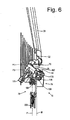
- Fig. 6 is a rear view of the derailleur in the high speed position
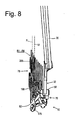
- Fig. 7 is a side view of the derailleur in a low speed position
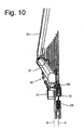
- Fig. 10 is a front view of the derailleur in the low speed position
- Fig. 12 is a laterally outer view of the rear derailleur attached to a conventional frame.
- Bicycle frame 14 is part of an overall bicycle frame that includes a chain stay 26, a seat stay 30 and a frame end 34 (commonly referred to as a dropout) that joins chain stay 26 and seat stay 26 together, typically by welding chain stay 26 and seat stay 30 to frame end 34.
- each of these frame structures is well known.
- this embodiment employs a configuration of frame end 34 that differs from common frame ends. More specifically, frame end 34 comprises a forward portion 38 and a rearward portion 42, wherein forward portion 38 extends from chain stay 26 and seat stay 30 to a horizontal position aligned with rotational axis X, and rearward portion 42 extends from the horizontal position aligned with rotational axis X rearward.
- axle receiving slot 46 dimensioned to receive rear axle 22 therein.
- axle receiving slot 46 is oriented substantially vertical with a slight incline and includes an open end 50 and a closed end 54, wherein open end 50 is disposed below closed end 54.
- Rearward portion 42 extends rearward and downward at an incline and forms a derailleur attachment structure in the form of a laterally projecting annular mounting boss 58 with an opening 60 dimensioned to receive a derailleur mounting bolt 62 therein.
- mounting boss 58 need no project laterally, in which case the surface of opening 60 forms the derailleur attachment structure.
- opening 60 may be located from approximately 180° to approximately 240° relative to rotational axis X, or, to facilitate measurement independently of axle 22, from approximately 180° to approximately 240° relative to closed end 54 of axle receiving slot 46.
- Rearward portion 42 of frame end 34 extends further rearward from mounting boss 58 to form a position setting abutment 66 that functions in a manner discussed below.
- An outer casing coupler 102 in the form of a hollow cylinder is disposed on an upper portion of transition portion 94, wherein outer casing coupler 102 is dimensioned to couple to and terminate an outer casing 106 of a Bowden cable 110 in a known manner.
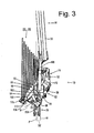
- Outer casing coupler 102 is positioned to be located rearward from rotational axis X and, more particularly, rearward from frame end 34 and at least partially laterally inward from mounting surface 90 of base member 70 as shown in Fig. 3 .
- Outer casing coupler 102 includes an outer casing receiving bore 104 having a bore axis B that is inclined relative to a pulley plane, or main central plane P described below.
- a cable adjusting bolt (not shown), the concept and structures of which are well known, may be mounted in outer casing receiving bore 104 so as to be disposed between outer casing coupler 102 and outer casing 106.
- link coupling portion 98 includes a support wall 114, an outer link mounting ear 118 and an inner link mounting ear 122.
- inner link mounting ear 122 is formed as an extension of transition portion 94 that inclines laterally inwardly from front to rear and from top to bottom
- support wall 114 extends laterally outwardly from inner mounting ear 122 so as to incline rearwardly from top to bottom and from transition portion 94 to the laterally outer end
- outer link mounting ear 118 extends downwardly from support wall 114 so as to incline laterally inwardly from front to rear and from top to bottom.
- Movable member 74 comprises a main body 130 and a link mounting frame 134.
- main body 130 comprises a generally cylindrical member that houses a torsion coil spring 138, one end of which is inserted into a spring mounting opening 142 formed in a laterally outer side wall 146 of main body 130.
- Link mounting frame 134 comprises an upper link mounting boss 150, a lower link mounting boss 154, and an upper chain guide link mounting frame 158, all of which are formed as one piece with main body 130.
- Linking mechanism 82 comprises linking members in the form of a laterally outer upper link 162 and a laterally inner lower link 166.
- a first end of upper link 162 is straddled by link coupling portion 98 of base member 70 and is pivotably connected thereto by a pivot shaft 170 that defines a pivot axis P1.
- the second end of upper link 162 is forked to straddle upper link mounting boss 150 of link mounting frame 134 of movable member 74 and is pivotably connected thereto by a pivot shaft 174 that defines a pivot axis P2. Because of this arrangement, a distance between the outermost edges of the first end of upper link 162 at base member 70 is less than a distance between the outermost edges of the second end of upper link 162 at movable member 74.
- An outer limit adjusting screw 186 and an inner limit adjusting screw 190 are mounted on upper link 162 to adjust the laterally outermost and laterally innermost positions of movable member 74, respectively, in a well known manner.
- a first end of lower link 166 is straddled by link coupling portion 98 of base member 70 and is pivotably connected thereto by a pivot shaft 178 that defines a pivot axis P3.
- An actuating arm 175 extends downwardly and laterally inwardly from the first end of lower link 166 so as to generally conform to the inclined contour formed by the outer peripheral surfaces of the plurality of sprockets R1-R8.
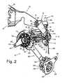
- a cable attachment structure in the form of a bolt 176 and a clamping washer 177 is provided at the outer end of actuating arm 175 to attach an inner cable 108 of Bowden cable 106 as shown in Fig. 2 .
- bolt 176 and washer 177 are disposed laterally inward from mounting surface 90 of base member 70 when chain guide 78 is located at a laterally outermost position.
- Lower link 166 is forked beginning in close proximity to pivot shaft 178 to form legs 179 and 180 ( Fig. 2 ) that extend toward movable member 74.
- Legs 179 and 180 straddle lower link mounting boss 154 of link mounting frame 134 of movable member 74 and is pivotably connected thereto by a pivot shaft 182 ( Fig. 1 ) that defines a pivot axis P4. Because of this arrangement, a distance between the outermost edges of the first end of lower link 166 at base member 70 is less than a distance between the outermost edges of the second end of lower link 166 at movable member 74.
- Chain guide 78 comprises an upper chain guide link 194, a first or upper guide pulley 198 rotatably mounted to upper chain guide link 194 through a pivot shaft 200, a lower chain guide link 202, and a second or lower tension pulley 206 rotatably mounted to lower chain guide link 202 through a pivot shaft 208.
- Upper chain guide link 194 is pivotably connected to upper chain guide link mounting frame 158 through a pivot shaft 210.
- Upper chain guide link 194 comprises a chain pushing member 214 and a chain regulating unit 218. Chain pushing member 214 is disposed between upper chain guide link mounting frame 158 and guide pulley 198, with an arcuate portion 222 disposed in close proximity to the teeth on guide pulley 198.
- Chain pushing member 214 is provided to push chain 18 when switching chain 18 from a smaller diameter sprocket to a larger diameter sprocket and to prevent chain 18 from derailing from guide pulley 198.
- Chain pushing member 214 rotates around a chain pushing member rotational axis defined by pivot shaft 210, which in this embodiment is offset from a first pulley axis defined by pivot shaft 200.
- both guide pulley 198 and chain pushing member 214 rotate around the chain pushing member rotational axis defined by pivot shaft 210.
- Chain regulating unit 218 comprises an inner plate 226, an outer plate 230 and a regulator pin 234.
- a radially inner end of inner plate 226 is coupled to pivot shaft 200, and a radially outer end of inner plate 226 is fastened to one end of regulator pin 234.
- a radially inner, portion of outer plate 230 joins with chain pushing member 214 and is coupled to pivot shaft 210, and a radially outer end of outer plate 230 is fastened to the other end of regulator pin 234.
- Inner plate 226 helps to prevent chain 18 from derailing from guide pulley 198 when switching chain 18 from a larger diameter sprocket to a smaller diameter sprocket
- outer plate 230 helps to prevent chain 18 from derailing from guide pulley 198 when switching chain 18 from a smaller diameter sprocket to a larger diameter sprocket.
- Regulator pin 234 helps to prevent excessive radial movement of chain 18 and ensures that upper chain guide link 194 rotates counterclockwise around pivot shaft 210 in response to forward swinging of chain 18.
- chain regulating unit 218 may be omitted in some embodiments.
- an upper end 205 of lower chain guide link 202 is pivotably coupled to main body 130 of movable member 74 through a pivot shaft 238 and includes a plurality of, e.g., three spring coupling openings 242.
- the other end of spring 138 mentioned above is inserted into one of the spring coupling openings 242 to set a desired biasing force on lower chain guide link 202.
- lower chain guide link 202 is biased clockwise in Fig. 1 .
- a lower end 207 of lower chain guide link 202 rotatably supports tension pulley 206 through pivot shaft 208 and nonrotatably supports a chain regulating unit 248.
- upper end 205 is substantially vertically straight and is laterally inwardly offset relative to lower end 207, which also is substantially vertically straight.
- chain regulating unit 248 comprises an inner plate 252, an outer plate 256 and a regulator pin 260.
- a radially inner end of inner plate 252 is coupled to pivot shaft 208, and a radially outer end of inner plate 252 is fastened to one end of regulator pin 260.
- outer plate 256 is formed as a part of lower chain guide link 202 and supports pivot shaft 208.
- a radially outer end of outer plate 256 is fastened to the other end of regulator pin 260.
- Inner plate 252 helps to prevent chain 18 from derailing from tension pulley 206 when switching chain 18 from a larger diameter sprocket to a smaller diameter sprocket
- outer plate 256 helps to prevent chain 18 from derailing from tension pulley 206 when switching chain 18 from a smaller diameter sprocket to a larger diameter sprocket.
- Regulator pin 260 helps to prevent excessive radial movement of chain 18.
- Chain regulating unit 248 may be omitted in some embodiments.
- base member 70, movable member 74, chain guide 78 and linking mechanism 82 are dimensioned so that guide pulley 198 is located at a range of from approximately 220° to approximately 270° relative to rotational axis X when chain guide 78 is disposed in the laterally outermost position.
- guide pulley 198 has a pulley plane or main central plane P that bisects guide pulley 198.
- each tooth on guide pulley 198 is symmetrical and centered on the pulley when viewed perpendicular to pivot shaft 200 so that pulley plane P is located in the center of guide pulley 198, and all of the pulley teeth lie in pulley plane P.
- pulley plane P also bisects tension pulley 206.
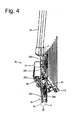
- the components are structured so that pulley plane P intersects at least one of upper link 162 or lower link 166 when chain guide 78 is disposed in a position somewhere between a laterally outermost rest position and a laterally innermost position (such as the laterally outermost position shown in Fig. 4 ).
- the laterally outermost position may be the laterally outermost position when derailleur 10 is removed from the bicycle.
- the laterally outermost position may be determined by the position of chain guide 78 with the derailleur at rest and subjected only to the biasing force of return spring 181, and the laterally innermost position is determined by the position of chain guide 78 when chain guide 78 is manually pulled to its laterally innermost position.
- the laterally outermost position may be determined by the position of chain guide 78 when it is set to be aligned with the smallest diameter rear sprocket Ri, and the laterally innermost position may be determined by the position of chain guide 78 when it is set to be aligned with the largest diameter rear sprocket R8.
- the word "between” is used in an inclusive sense.
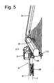
- pulley plane P intersects at least one of pivot axis P1 or pivot axis P3 when measured across all components at the coupling when chain guide 78 is disposed in a position somewhere between a laterally outermost rest position and a laterally innermost position (such as the laterally outermost position shown in Fig. 6 ).
- pivot shaft 170 defines pivot axis P1 and couples upper link 162 to base member 70. The laterally outer tip of pivot shaft 170 is exposed at outer link mounting member 118, whereas the laterally inner tip of pivot shaft 170 is inserted into a blind bore (not shown) in inner link mounting member 122 so that the inner lateral tip is not exposed at inner link mounting member 122.
- pivot shaft 178 defines pivot axis P3 and couples lower link 166 to base member 70.
- the laterally outer tip of pivot shaft 178 is exposed at outer link mounting member 118, whereas the laterally inner tip of pivot shaft 178 is inserted into a blind bore (not shown) in inner link mounting member 122 so that the inner lateral tip is not exposed at inner link mounting member 122.
- the length of pivot axis P3 measured across all components at the coupling therefore extends from the laterally outer tip of pivot shaft 178 at pivot axis P3 to the laterally inner surface of inner link mounting member 122 at pivot axis P3.
- pulley plane P intersects both upper link 162 and lower link 166 as well as pivot axes P1 and P3 when chain guide 78 is disposed in a position somewhere between the laterally outermost position and the laterally innermost position, such as the laterally outermost position shown in Fig. 4 .
- second pivot axis P2 as measured according to the definition above is disposed entirely on the laterally outer side of pulley plane P (as well as movable member plane M) in the position shown in Fig. 3 .
- pulley plane P intersects a space S1 between any facing surfaces (e.g., surfaces 261 and 262 shown in Fig. 2 ) of upper link 162 and lower link 166 as shown in Fig. 4 .
- Pulley plane P also intersects base member 70 when chain guide 78 is disposed in a position somewhere between the laterally outermost position and the laterally innermost position, such as the laterally outermost position shown in Fig. 3 .
- a movable member plane M (or simply called a plane M) that is substantially parallel to pulley plane P intersects an innermost surface 264 of movable member 74.
- movable member plane M is parallel to pulley plane P at a laterally innermost edge of the movable member and innermost surface 264 is coplanar with movable member plane M, although other configurations are possible since movable member 74 may have many different shapes.
- Movable member plane M intersects both upper link 162 and lower link 166, pivot axes P 1 and P3, and the space S1 between facing surfaces of upper link 162 and lower link 16 when chain guide 78 is disposed in a position somewhere between the laterally outermost position and the laterally innermost position. Furthermore, at least a portion of a space S2 between movable member plane M and pulley plane P intersects the space S 1 between facing surfaces of upper link 162 and lower link 16 when chain guide 78 is disposed in a position somewhere between the laterally outermost position and the laterally innermost position, such as the laterally outermost position shown in Fig. 4 .
- the space S2 at least partially coincides with the space S1 circumscribed by the base member 70, the movable member 74 and the linking mechanism 82 when chain guide 78 is disposed in a position somewhere between the laterally outermost position and the laterally innermost position, such as the laterally outermost position shown in Fig. 4
- derailleur 10 has a very low lateral profile.
- chain guide 78 when chain guide 78 is located in the laterally outermost position shown in Fig. 3 , the components barely protrude laterally outward relative to frame 14.
- Actuating arm 175 and portions of linking mechanism 82 are disposed laterally inward from pulley plane P and movable member plane M and follow the diagonal contour of sprockets R1-R8, thereby forming a very compact structure.
- mounting boss 58 is the laterally outermost portion of derailleur 10. In fact, mounting boss 58 does not even protrude laterally outward relative to chain stay 26 or seat stay 30. In this position, actuating arm 175 and linking mechanism 82 again following the diagonal contour of sprockets R1-R8.
- Prior art derailleurs do not have the ability to have such a low profile.
- the chain guide in prior art derailleurs has a chain pushing member that is formed as one piece with an inner plate that extends from the upper guide pulley to the lower tension pulley, and this inner plate limits the ability of the chain guide to move laterally outwardly.
- chain pushing member 214 is dimensioned to as not to interfere with the ability of chain guide 78 to move laterally outwardly.
- the two-piece structure of chain guide 78 further facilitates such lateral movement.
- the base member and linking mechanism in prior art derailleurs are dimensioned to be mounted substantially below, or even in front of, the rotational axis X of the rear wheel, and this requires sufficient lateral spacing to ensure that the linking mechanism does not strike the sprockets during operation.
- base member 70, upper link 162, lower link 166 movable member 74 and chain guide 78 in the presently disclosed embodiment are dimensioned so that guide pulley 198 is located at a range of from approximately 220° to approximately 270° relative to rotational axis X when chain guide 78 is disposed in the laterally outermost position, the lateral distance required for the components further decreases because the linking mechanism is able to more closely follow the contour formed by the outer peripheral surfaces of the plurality of sprockets R1-R8.
- the features described herein contribute to a markedly low profile derailleur, not all features are required, depending upon the application.
- Fig. 12 is a laterally outer view of rear derailleur 10 mounted to a frame end 300 of a conventional frame 14'.
- frame end 300 comprises a forward portion 304 and a rearward portion 308, wherein forward portion 304 extends from chain stay 26 and seat stay 30 to a horizontal position aligned with rotational axis X, and rearward portion 308 extends from a horizontal position aligned with rotational axis X rearwardly and substantially vertically downwardly.
- a junction between forward portion 304 and rearward portion 308 forms an axle receiving slot 312 dimensioned to receive rear axle 22 therein.
- axle receiving slot 312 again is oriented substantially vertically with a slight incline and defines an open end 316 and a closed end 320, wherein open end 316 is disposed below closed end 320.
- Rearward portion 308 forms an annular mounting boss 324 with an opening (not shown) dimensioned to receive a mounting bolt 328 therein.
- Extension member 330 is dimensioned such that, when extension member 330 is attached to frame end 300, mounting opening 350, and hence boss member 86 of base member 70 of derailleur 10, is located from approximately 180° to approximately 240° relative to axle receiving opening 312, from approximately 180° to approximately 240° relative to rotational axis X, or, to facilitate measurement independently of axle 22, from approximately 180° to approximately 240° relative to closed end 320 of axle receiving opening 312.
- Rearward portion 38 extends further rearwardly from derailleur mounting opening 350 to form a position setting abutment 354 that functions in the same manner as position setting abutment 66 in the first embodiment.
Claims (10)
- Dérailleur arrière de bicyclette comprenant :un élément de base (70),un élément mobile (74), qui supporte un guide de chaîne (78), comprenant une première poulie qui tourne autour d'un premier axe de poulie, la poulie ayant un plan de poulie (P) ; etun premier élément de liaison relié entre l'élément de base (70) et l'élément mobile (74), de sorte que le guide de chaîne se déplace latéralement par rapport à l'élément de base (70) entre une première position latérale et une deuxième position latérale ;un deuxième élément de liaison relié entre l'élément de base (70) et l'élément mobile (74), de sorte que le guide de chaîne (78) se déplace latéralement par rapport à l'élément de base (70) entre une première position latérale et une deuxième position latérale ;dans lequel le premier élément de liaison (162, 166) est relié à l'élément de base (70) pour pivotement autour d'un premier axe pivot (P1, P3) qui s'étend à travers tous les composants au niveau de la liaison du premier élément de liaison et de l'élément de base ;dans lequel le premier élément de liaison (162, 166) est relié à l'élément mobile (74) pour pivotement autour d'un deuxième axe pivot (P2, P4) qui s'étend à travers tous les composants au niveau de la liaison du premier élément de liaison et de l'élément mobile,dans lequel le plan de poulie (P) intersecte le premier axe pivot lorsque le guide de chaîne est situé à une première position entre la première position latérale et la deuxième position latérale, de sorte qu'un espace circonscrit par l'élément de base, l'élément mobile et les éléments de liaison (162, 166) coïncide au moins en partie avec un espace entre un plan parallèle audit plan de poulie, au niveau d'un coin ea plus interne de l'élément mobile, et le plan de poulie dans au moins une position de la poulie,et dans lequel au moins une partie du premier axe pivot est disposée sur un côté latéralement interne du plan de poulie, et dans lequel au moins une partie du deuxième axe pivot est disposée sur un côté latéralement externe du plan de poulie, caractérisé en ce quel'élément de base (70) est structuré pour être monté à une extrémité de cadre arrière,dans lequel une première largeur du premier élément de liaison au niveau du premier emplacement de pivot est différente d'une deuxième largeur du premier élément de liaison au niveau du deuxième emplacement de pivot,le premier élément de liaison chevauchant l'un de l'élément de base et de l'élément mobile, et le premier élément de liaison étant chevauché par l'autre de l'élément de base et de l'élément mobile.
- Dérailleur selon la revendication 1, comprenant en outre un élément de sollicitation qui sollicite le guide de chaîne (78) de sorte que le guide de chaîne est ajusté/fixé au niveau de la première position latérale, dans lequel le plan de poulie (P) intersecte le premier axe pivot lorsque le guide de chaîne est situé au niveau de la première position latérale.
- Dérailleur selon la revendication 1 ou 2, dans lequel la première position latérale est une position latéralement la plus externe du guide de chaîne.
- Dérailleur selon l'une quelconque des revendications 1 à 3, dans lequel un plan d'élément mobile intersecte une surface la plus interne de l'élément mobile (74) et est orienté sensiblement parallèle au plan de poulie (P), et dans lequel le plan d'élément mobile intersecte le premier axe pivot lorsque le guide de chaîne est situé au niveau de la première position latérale.
- Dérailleur selon l'une quelconque des revendications 1 à 4, dans lequel au moins une partie du premier axe pivot est disposée sur un côté latéralement interne du plan de poulie.
- Dérailleur selon l'une quelconque des revendications 1 à 5, dans lequel le plan de poulie (P) intersecte le premier élément de liaison lorsque le guide de chaîne est situé au niveau d'une première position entre la première position latérale et la deuxième position latérale.
- Dérailleur selon l'une quelconque des revendications 1 à 6, comprenant en outre un deuxième élément de liaison (162), relié entre l'élément de base et l'élément mobile, de sorte que le guide de chaîne se déplace latéralement entre la première position latérale et la deuxième position latérale, dans lequel la deuxième position latérale est disposée latéralement vers l'extérieur du premier élément de liaison.
- Dérailleur selon la revendication 7, dans lequel le plan de poulie intersecte le deuxième élément de liaison lorsque le guide de chaîne est situé au niveau d'une deuxième position entre la première position latérale et la deuxième position latérale.
- Dérailleur selon la revendication 7 ou 8, dans lequel le plan de poulie intersecte un espace entre le premier élément de liaison et le deuxième élément de liaison, lorsque le guide de chaîne est situé au niveau de la première position.
- Dérailleur selon la revendication 9, dans lequel un plan d'élément mobile (M) intersecte une surface la plus interne de l'élément mobile et est orienté sensiblement parallèle au plan de poulie, et dans lequel au moins une partie d'un espace entre le plan de poulie et le plan d'élément mobile intersecte l'espace entre le premier élément de liaison et le deuxième élément de liaison.
Priority Applications (1)
| Application Number | Priority Date | Filing Date | Title |
|---|---|---|---|
| EP10183792A EP2301835A1 (fr) | 2006-02-28 | 2006-02-28 | Structure arriére d'un vélo |
Applications Claiming Priority (1)
| Application Number | Priority Date | Filing Date | Title |
|---|---|---|---|
| EP20060004024 EP1826114B1 (fr) | 2006-02-28 | 2006-02-28 | Assemblage d'un cadre de bicyclette et un dérailleur arrière à faible encombrement |
Related Parent Applications (2)
| Application Number | Title | Priority Date | Filing Date |
|---|---|---|---|
| EP06004024.3 Division | 2006-02-28 | ||
| EP20060004024 Division EP1826114B1 (fr) | 2006-02-28 | 2006-02-28 | Assemblage d'un cadre de bicyclette et un dérailleur arrière à faible encombrement |
Related Child Applications (1)
| Application Number | Title | Priority Date | Filing Date |
|---|---|---|---|
| EP10183792.0 Division-Into | 2010-09-30 |
Publications (2)
| Publication Number | Publication Date |
|---|---|
| EP2000399A1 EP2000399A1 (fr) | 2008-12-10 |
| EP2000399B1 true EP2000399B1 (fr) | 2011-09-28 |
Family
ID=36563616
Family Applications (4)
| Application Number | Title | Priority Date | Filing Date |
|---|---|---|---|
| EP10183792A Withdrawn EP2301835A1 (fr) | 2006-02-28 | 2006-02-28 | Structure arriére d'un vélo |
| EP08161785A Revoked EP2000399B1 (fr) | 2006-02-28 | 2006-02-28 | Dérailleur |
| EP20060004024 Revoked EP1826114B1 (fr) | 2006-02-28 | 2006-02-28 | Assemblage d'un cadre de bicyclette et un dérailleur arrière à faible encombrement |
| EP06022723A Active EP1829780B1 (fr) | 2006-02-28 | 2006-02-28 | Dérailleur |
Family Applications Before (1)
| Application Number | Title | Priority Date | Filing Date |
|---|---|---|---|
| EP10183792A Withdrawn EP2301835A1 (fr) | 2006-02-28 | 2006-02-28 | Structure arriére d'un vélo |
Family Applications After (2)
| Application Number | Title | Priority Date | Filing Date |
|---|---|---|---|
| EP20060004024 Revoked EP1826114B1 (fr) | 2006-02-28 | 2006-02-28 | Assemblage d'un cadre de bicyclette et un dérailleur arrière à faible encombrement |
| EP06022723A Active EP1829780B1 (fr) | 2006-02-28 | 2006-02-28 | Dérailleur |
Country Status (2)
| Country | Link |
|---|---|
| EP (4) | EP2301835A1 (fr) |
| DE (1) | DE602006014793D1 (fr) |
Families Citing this family (5)
| Publication number | Priority date | Publication date | Assignee | Title |
|---|---|---|---|---|
| TW201641348A (zh) * | 2015-05-20 | 2016-12-01 | Zhan Zhi Green Energy Co Ltd | 多段變速三輪腳踏車可後踩倒車驅動裝置 |
| DE102018001253A1 (de) | 2017-03-20 | 2018-09-20 | Sram Deutschland Gmbh | Hinteres Schaltwerk zur koaxialen Montage |
| US10501147B2 (en) * | 2017-08-22 | 2019-12-10 | Shimano Inc. | Bicycle derailleur |
| US10981626B2 (en) | 2018-03-20 | 2021-04-20 | Sram Deutschland Gmbh | Drive arrangement for a bicycle |
| DE102020201229A1 (de) | 2019-03-22 | 2020-09-24 | Sram Deutschland Gmbh | Koaxiale Schaltwerksanbindung |
Family Cites Families (22)
| Publication number | Priority date | Publication date | Assignee | Title |
|---|---|---|---|---|
| BE425459A (fr) * | ||||
| US534680A (en) * | 1895-02-26 | Ments | ||
| FR760565A (fr) * | 1933-08-26 | 1934-02-26 | Changement de vitesse pour cycles | |
| FR799947A (fr) * | 1935-03-27 | 1936-06-23 | Tendeur dérailleur de chaîne pour bicyclettes | |
| FR869777A (fr) | 1941-02-05 | 1942-02-16 | Dérailleur pour bicyclette et, en général pour tout appareil à transmission par chaîne | |
| CH284668A (de) * | 1950-08-23 | 1952-07-31 | Trost Ernst | Wechselvorrichtung für ein Kettenübersetzungsgetriebe an einem Fahrrad. |
| FR2314093A1 (fr) * | 1975-06-12 | 1977-01-07 | Huret Roger | Derailleur pour bicyclette |
| JPS591901Y2 (ja) * | 1979-02-15 | 1984-01-19 | 株式会社シマノ | リヤデイレ−ラ− |
| JPS6015516B2 (ja) * | 1979-12-19 | 1985-04-19 | 株式会社シマノ | 自転車用デイレ−ラ− |
| EP0032049A3 (fr) * | 1979-12-29 | 1982-10-27 | Shimano Industrial Company Limited | Dérailleur de cycle et son utilisation |
| US4437848A (en) * | 1980-03-15 | 1984-03-20 | Shimano Industrial Company Limited | Derailleur for a bicycle |
| US4443208A (en) * | 1980-12-16 | 1984-04-17 | Bridgestone Cycle Co. Ltd. | Speed-change gear mounted outside a bicycle |
| JPH0671916B2 (ja) * | 1984-12-29 | 1994-09-14 | 島野工業株式会社 | 自転車用デイレ−ラ− |
| DE4022473C2 (de) * | 1990-07-14 | 1994-01-20 | Rolf Dr Meissner | Kettenschaltung für ein Fahrrad |
| WO1992010395A1 (fr) | 1990-12-08 | 1992-06-25 | Maeda Industries, Ltd. | Mecanisme de changement de vitesses pour bicyclette |
| JPH0820375A (ja) * | 1991-11-11 | 1996-01-23 | Mori San Tour:Kk | 自転車用変速機構 |
| DE9422229U1 (de) | 1993-02-03 | 1999-04-08 | Shimano Kk | Hinteres Schaltwerk für ein Fahrrad |
| JP3372616B2 (ja) * | 1993-11-30 | 2003-02-04 | 株式会社シマノ | 自転車用ディレーラ |
| US5456637A (en) * | 1994-10-07 | 1995-10-10 | Chang; Shu-Gen | Chain shifting device for bicycle |
| DE19915334A1 (de) * | 1999-04-03 | 2000-10-05 | Sram De Gmbh | Umlenkrolle für ein Seil zur Betätigung einer Kettenschaltung |
| US6287228B1 (en) | 1999-11-12 | 2001-09-11 | Shimano, Inc. | Rear derailleur with cable guide roller |
| US6354971B1 (en) * | 2000-02-02 | 2002-03-12 | Brigham Young University | Compliant derailleur |
-
2006
- 2006-02-28 EP EP10183792A patent/EP2301835A1/fr not_active Withdrawn
- 2006-02-28 DE DE200660014793 patent/DE602006014793D1/de active Active
- 2006-02-28 EP EP08161785A patent/EP2000399B1/fr not_active Revoked
- 2006-02-28 EP EP20060004024 patent/EP1826114B1/fr not_active Revoked
- 2006-02-28 EP EP06022723A patent/EP1829780B1/fr active Active
Also Published As
| Publication number | Publication date |
|---|---|
| EP1826114A1 (fr) | 2007-08-29 |
| EP1829780A1 (fr) | 2007-09-05 |
| EP1826114B1 (fr) | 2010-06-09 |
| DE602006014793D1 (de) | 2010-07-22 |
| EP2301835A1 (fr) | 2011-03-30 |
| EP1829780B1 (fr) | 2010-10-27 |
| EP2000399A1 (fr) | 2008-12-10 |
Similar Documents
| Publication | Publication Date | Title |
|---|---|---|
| US8012052B2 (en) | Low profile rear derailleur with cable guide | |
| US8277346B2 (en) | Low profile rear derailleur | |
| EP1939085B1 (fr) | Dérailleur arrière à profil bas doté d'un espace pour recevoir la chaîne | |
| EP2078668B2 (fr) | Dérailleur arrière à profil bas | |
| JP3373195B2 (ja) | 自転車用ディレイラアッセンブリ | |
| EP1632429B1 (fr) | Dérailleur arrière pour bicyclette | |
| EP2000399B1 (fr) | Dérailleur | |
| CN101704400A (zh) | 低轮廓后拨链器 | |
| CZ20004178A3 (cs) | Zadní přesmykač s lankovým vodicím válečkem |
Legal Events
| Date | Code | Title | Description |
|---|---|---|---|
| PUAI | Public reference made under article 153(3) epc to a published international application that has entered the european phase |
Free format text: ORIGINAL CODE: 0009012 |
|
| AC | Divisional application: reference to earlier application |
Ref document number: 1826114 Country of ref document: EP Kind code of ref document: P |
|
| AK | Designated contracting states |
Kind code of ref document: A1 Designated state(s): AT BE BG CH CY CZ DE DK EE ES FI FR GB GR HU IE IS IT LI LT LU LV MC NL PL PT RO SE SI SK TR |
|
| 17P | Request for examination filed |
Effective date: 20090610 |
|
| AKX | Designation fees paid |
Designated state(s): DE FR IT NL |
|
| 17Q | First examination report despatched |
Effective date: 20100316 |
|
| GRAP | Despatch of communication of intention to grant a patent |
Free format text: ORIGINAL CODE: EPIDOSNIGR1 |
|
| GRAS | Grant fee paid |
Free format text: ORIGINAL CODE: EPIDOSNIGR3 |
|
| GRAA | (expected) grant |
Free format text: ORIGINAL CODE: 0009210 |
|
| AC | Divisional application: reference to earlier application |
Ref document number: 1826114 Country of ref document: EP Kind code of ref document: P |
|
| AK | Designated contracting states |
Kind code of ref document: B1 Designated state(s): DE FR IT NL |
|
| REG | Reference to a national code |
Ref country code: DE Ref legal event code: R096 Ref document number: 602006024772 Country of ref document: DE Effective date: 20111201 |
|
| REG | Reference to a national code |
Ref country code: NL Ref legal event code: VDEP Effective date: 20110928 |
|
| PG25 | Lapsed in a contracting state [announced via postgrant information from national office to epo] |
Ref country code: NL Free format text: LAPSE BECAUSE OF FAILURE TO SUBMIT A TRANSLATION OF THE DESCRIPTION OR TO PAY THE FEE WITHIN THE PRESCRIBED TIME-LIMIT Effective date: 20110928 |
|
| PLBI | Opposition filed |
Free format text: ORIGINAL CODE: 0009260 |
|
| PLAX | Notice of opposition and request to file observation + time limit sent |
Free format text: ORIGINAL CODE: EPIDOSNOBS2 |
|
| 26 | Opposition filed |
Opponent name: SRAM DEUTSCHLAND GMBH Effective date: 20120627 |
|
| REG | Reference to a national code |
Ref country code: DE Ref legal event code: R026 Ref document number: 602006024772 Country of ref document: DE Effective date: 20120627 |
|
| PLAF | Information modified related to communication of a notice of opposition and request to file observations + time limit |
Free format text: ORIGINAL CODE: EPIDOSCOBS2 |
|
| PLBB | Reply of patent proprietor to notice(s) of opposition received |
Free format text: ORIGINAL CODE: EPIDOSNOBS3 |
|
| PLAY | Examination report in opposition despatched + time limit |
Free format text: ORIGINAL CODE: EPIDOSNORE2 |
|
| PLBC | Reply to examination report in opposition received |
Free format text: ORIGINAL CODE: EPIDOSNORE3 |
|
| PGFP | Annual fee paid to national office [announced via postgrant information from national office to epo] |
Ref country code: FR Payment date: 20140211 Year of fee payment: 9 |
|
| PLAB | Opposition data, opponent's data or that of the opponent's representative modified |
Free format text: ORIGINAL CODE: 0009299OPPO |
|
| R26 | Opposition filed (corrected) |
Opponent name: SRAM DEUTSCHLAND GMBH Effective date: 20120627 |
|
| PGFP | Annual fee paid to national office [announced via postgrant information from national office to epo] |
Ref country code: DE Payment date: 20150224 Year of fee payment: 10 |
|
| RDAF | Communication despatched that patent is revoked |
Free format text: ORIGINAL CODE: EPIDOSNREV1 |
|
| APAH | Appeal reference modified |
Free format text: ORIGINAL CODE: EPIDOSCREFNO |
|
| APBM | Appeal reference recorded |
Free format text: ORIGINAL CODE: EPIDOSNREFNO |
|
| APBP | Date of receipt of notice of appeal recorded |
Free format text: ORIGINAL CODE: EPIDOSNNOA2O |
|
| REG | Reference to a national code |
Ref country code: DE Ref legal event code: R103 Ref document number: 602006024772 Country of ref document: DE Ref country code: DE Ref legal event code: R064 Ref document number: 602006024772 Country of ref document: DE |
|
| APBU | Appeal procedure closed |
Free format text: ORIGINAL CODE: EPIDOSNNOA9O |
|
| RDAG | Patent revoked |
Free format text: ORIGINAL CODE: 0009271 |
|
| STAA | Information on the status of an ep patent application or granted ep patent |
Free format text: STATUS: PATENT REVOKED |
|
| 27W | Patent revoked |
Effective date: 20150924 |
|
| REG | Reference to a national code |
Ref country code: FR Ref legal event code: ST Effective date: 20151030 |
|
| PG25 | Lapsed in a contracting state [announced via postgrant information from national office to epo] |
Ref country code: FR Free format text: LAPSE BECAUSE OF NON-PAYMENT OF DUE FEES Effective date: 20150302 |
|
| PGFP | Annual fee paid to national office [announced via postgrant information from national office to epo] |
Ref country code: IT Payment date: 20160222 Year of fee payment: 11 |