EP2000399B1 - Derailleur - Google Patents
Derailleur Download PDFInfo
- Publication number
- EP2000399B1 EP2000399B1 EP08161785A EP08161785A EP2000399B1 EP 2000399 B1 EP2000399 B1 EP 2000399B1 EP 08161785 A EP08161785 A EP 08161785A EP 08161785 A EP08161785 A EP 08161785A EP 2000399 B1 EP2000399 B1 EP 2000399B1
- Authority
- EP
- European Patent Office
- Prior art keywords
- pulley
- chain guide
- plane
- laterally
- movable member
- Prior art date
- Legal status (The legal status is an assumption and is not a legal conclusion. Google has not performed a legal analysis and makes no representation as to the accuracy of the status listed.)
- Revoked
Links
Images


Classifications
-
- B—PERFORMING OPERATIONS; TRANSPORTING
- B62—LAND VEHICLES FOR TRAVELLING OTHERWISE THAN ON RAILS
- B62M—RIDER PROPULSION OF WHEELED VEHICLES OR SLEDGES; POWERED PROPULSION OF SLEDGES OR SINGLE-TRACK CYCLES; TRANSMISSIONS SPECIALLY ADAPTED FOR SUCH VEHICLES
- B62M9/00—Transmissions characterised by use of an endless chain, belt, or the like
- B62M9/04—Transmissions characterised by use of an endless chain, belt, or the like of changeable ratio
- B62M9/06—Transmissions characterised by use of an endless chain, belt, or the like of changeable ratio using a single chain, belt, or the like
- B62M9/10—Transmissions characterised by use of an endless chain, belt, or the like of changeable ratio using a single chain, belt, or the like involving different-sized wheels, e.g. rear sprocket chain wheels selectively engaged by the chain, belt, or the like
- B62M9/12—Transmissions characterised by use of an endless chain, belt, or the like of changeable ratio using a single chain, belt, or the like involving different-sized wheels, e.g. rear sprocket chain wheels selectively engaged by the chain, belt, or the like the chain, belt, or the like being laterally shiftable, e.g. using a rear derailleur
- B62M9/121—Rear derailleurs
- B62M9/124—Mechanisms for shifting laterally
- B62M9/1242—Mechanisms for shifting laterally characterised by the linkage mechanisms
Definitions
- said base member is having a cable sleeve fixation portion, in particular substantially extending in a direction corresponding to the pivotal movement of the link members.
- one of the pulley mount portions is a floating mount portion, in particular having a counter weight portion.
- a bicycle rear derailleur comprises a base member; a movable member that supports a chain guide including a first pulley that rotates around a first pulley axis, wherein the pulley has a pulley plane or a main central plane; and a first linking member coupled between the base member and the movable member so that the chain guide moves laterally relative to the base member between a first lateral position and a second lateral position.
- a bicycle rear derailleur is comprising: a base member; a movable member that supports a chain guide including a first pulley that rotates around a first pulley axis, wherein the pulley has a pulley plane or a main central plane; and a first linking member coupled between the base member and the movable member so that the chain guide moves laterally relative to the base member between a first lateral position and a second lateral position; wherein the pulley plane intersects the first linking member when the chain guide is located at a first position between the first lateral position and the second lateral position.
- the chain guide could eventually include a second pulley that rotates around a second pulley axis, wherein the first pulley is disposed above the second pulley, and wherein the first pulley is located at a range of from approximately 220° to approximately 270° relative to the rotational axis when the chain guide is disposed in a laterally outermost position.
- Fig. 6 is a rear view of the derailleur in the high speed position
- Fig. 7 is a side view of the derailleur in a low speed position
- Fig. 10 is a front view of the derailleur in the low speed position
- Fig. 12 is a laterally outer view of the rear derailleur attached to a conventional frame.
- Bicycle frame 14 is part of an overall bicycle frame that includes a chain stay 26, a seat stay 30 and a frame end 34 (commonly referred to as a dropout) that joins chain stay 26 and seat stay 26 together, typically by welding chain stay 26 and seat stay 30 to frame end 34.
- each of these frame structures is well known.
- this embodiment employs a configuration of frame end 34 that differs from common frame ends. More specifically, frame end 34 comprises a forward portion 38 and a rearward portion 42, wherein forward portion 38 extends from chain stay 26 and seat stay 30 to a horizontal position aligned with rotational axis X, and rearward portion 42 extends from the horizontal position aligned with rotational axis X rearward.
- axle receiving slot 46 dimensioned to receive rear axle 22 therein.
- axle receiving slot 46 is oriented substantially vertical with a slight incline and includes an open end 50 and a closed end 54, wherein open end 50 is disposed below closed end 54.
- Rearward portion 42 extends rearward and downward at an incline and forms a derailleur attachment structure in the form of a laterally projecting annular mounting boss 58 with an opening 60 dimensioned to receive a derailleur mounting bolt 62 therein.
- mounting boss 58 need no project laterally, in which case the surface of opening 60 forms the derailleur attachment structure.
- opening 60 may be located from approximately 180° to approximately 240° relative to rotational axis X, or, to facilitate measurement independently of axle 22, from approximately 180° to approximately 240° relative to closed end 54 of axle receiving slot 46.
- Rearward portion 42 of frame end 34 extends further rearward from mounting boss 58 to form a position setting abutment 66 that functions in a manner discussed below.
- An outer casing coupler 102 in the form of a hollow cylinder is disposed on an upper portion of transition portion 94, wherein outer casing coupler 102 is dimensioned to couple to and terminate an outer casing 106 of a Bowden cable 110 in a known manner.
- Outer casing coupler 102 is positioned to be located rearward from rotational axis X and, more particularly, rearward from frame end 34 and at least partially laterally inward from mounting surface 90 of base member 70 as shown in Fig. 3 .
- Outer casing coupler 102 includes an outer casing receiving bore 104 having a bore axis B that is inclined relative to a pulley plane, or main central plane P described below.
- a cable adjusting bolt (not shown), the concept and structures of which are well known, may be mounted in outer casing receiving bore 104 so as to be disposed between outer casing coupler 102 and outer casing 106.
- link coupling portion 98 includes a support wall 114, an outer link mounting ear 118 and an inner link mounting ear 122.
- inner link mounting ear 122 is formed as an extension of transition portion 94 that inclines laterally inwardly from front to rear and from top to bottom
- support wall 114 extends laterally outwardly from inner mounting ear 122 so as to incline rearwardly from top to bottom and from transition portion 94 to the laterally outer end
- outer link mounting ear 118 extends downwardly from support wall 114 so as to incline laterally inwardly from front to rear and from top to bottom.
- Movable member 74 comprises a main body 130 and a link mounting frame 134.
- main body 130 comprises a generally cylindrical member that houses a torsion coil spring 138, one end of which is inserted into a spring mounting opening 142 formed in a laterally outer side wall 146 of main body 130.
- Link mounting frame 134 comprises an upper link mounting boss 150, a lower link mounting boss 154, and an upper chain guide link mounting frame 158, all of which are formed as one piece with main body 130.
- Linking mechanism 82 comprises linking members in the form of a laterally outer upper link 162 and a laterally inner lower link 166.
- a first end of upper link 162 is straddled by link coupling portion 98 of base member 70 and is pivotably connected thereto by a pivot shaft 170 that defines a pivot axis P1.
- the second end of upper link 162 is forked to straddle upper link mounting boss 150 of link mounting frame 134 of movable member 74 and is pivotably connected thereto by a pivot shaft 174 that defines a pivot axis P2. Because of this arrangement, a distance between the outermost edges of the first end of upper link 162 at base member 70 is less than a distance between the outermost edges of the second end of upper link 162 at movable member 74.
- An outer limit adjusting screw 186 and an inner limit adjusting screw 190 are mounted on upper link 162 to adjust the laterally outermost and laterally innermost positions of movable member 74, respectively, in a well known manner.
- a first end of lower link 166 is straddled by link coupling portion 98 of base member 70 and is pivotably connected thereto by a pivot shaft 178 that defines a pivot axis P3.
- An actuating arm 175 extends downwardly and laterally inwardly from the first end of lower link 166 so as to generally conform to the inclined contour formed by the outer peripheral surfaces of the plurality of sprockets R1-R8.
- a cable attachment structure in the form of a bolt 176 and a clamping washer 177 is provided at the outer end of actuating arm 175 to attach an inner cable 108 of Bowden cable 106 as shown in Fig. 2 .
- bolt 176 and washer 177 are disposed laterally inward from mounting surface 90 of base member 70 when chain guide 78 is located at a laterally outermost position.
- Lower link 166 is forked beginning in close proximity to pivot shaft 178 to form legs 179 and 180 ( Fig. 2 ) that extend toward movable member 74.
- Legs 179 and 180 straddle lower link mounting boss 154 of link mounting frame 134 of movable member 74 and is pivotably connected thereto by a pivot shaft 182 ( Fig. 1 ) that defines a pivot axis P4. Because of this arrangement, a distance between the outermost edges of the first end of lower link 166 at base member 70 is less than a distance between the outermost edges of the second end of lower link 166 at movable member 74.
- Chain guide 78 comprises an upper chain guide link 194, a first or upper guide pulley 198 rotatably mounted to upper chain guide link 194 through a pivot shaft 200, a lower chain guide link 202, and a second or lower tension pulley 206 rotatably mounted to lower chain guide link 202 through a pivot shaft 208.
- Upper chain guide link 194 is pivotably connected to upper chain guide link mounting frame 158 through a pivot shaft 210.
- Upper chain guide link 194 comprises a chain pushing member 214 and a chain regulating unit 218. Chain pushing member 214 is disposed between upper chain guide link mounting frame 158 and guide pulley 198, with an arcuate portion 222 disposed in close proximity to the teeth on guide pulley 198.
- Chain pushing member 214 is provided to push chain 18 when switching chain 18 from a smaller diameter sprocket to a larger diameter sprocket and to prevent chain 18 from derailing from guide pulley 198.
- Chain pushing member 214 rotates around a chain pushing member rotational axis defined by pivot shaft 210, which in this embodiment is offset from a first pulley axis defined by pivot shaft 200.
- both guide pulley 198 and chain pushing member 214 rotate around the chain pushing member rotational axis defined by pivot shaft 210.
- Chain regulating unit 218 comprises an inner plate 226, an outer plate 230 and a regulator pin 234.
- a radially inner end of inner plate 226 is coupled to pivot shaft 200, and a radially outer end of inner plate 226 is fastened to one end of regulator pin 234.
- a radially inner, portion of outer plate 230 joins with chain pushing member 214 and is coupled to pivot shaft 210, and a radially outer end of outer plate 230 is fastened to the other end of regulator pin 234.
- Inner plate 226 helps to prevent chain 18 from derailing from guide pulley 198 when switching chain 18 from a larger diameter sprocket to a smaller diameter sprocket
- outer plate 230 helps to prevent chain 18 from derailing from guide pulley 198 when switching chain 18 from a smaller diameter sprocket to a larger diameter sprocket.
- Regulator pin 234 helps to prevent excessive radial movement of chain 18 and ensures that upper chain guide link 194 rotates counterclockwise around pivot shaft 210 in response to forward swinging of chain 18.
- chain regulating unit 218 may be omitted in some embodiments.
- an upper end 205 of lower chain guide link 202 is pivotably coupled to main body 130 of movable member 74 through a pivot shaft 238 and includes a plurality of, e.g., three spring coupling openings 242.
- the other end of spring 138 mentioned above is inserted into one of the spring coupling openings 242 to set a desired biasing force on lower chain guide link 202.
- lower chain guide link 202 is biased clockwise in Fig. 1 .
- a lower end 207 of lower chain guide link 202 rotatably supports tension pulley 206 through pivot shaft 208 and nonrotatably supports a chain regulating unit 248.
- upper end 205 is substantially vertically straight and is laterally inwardly offset relative to lower end 207, which also is substantially vertically straight.
- chain regulating unit 248 comprises an inner plate 252, an outer plate 256 and a regulator pin 260.
- a radially inner end of inner plate 252 is coupled to pivot shaft 208, and a radially outer end of inner plate 252 is fastened to one end of regulator pin 260.
- outer plate 256 is formed as a part of lower chain guide link 202 and supports pivot shaft 208.
- a radially outer end of outer plate 256 is fastened to the other end of regulator pin 260.
- Inner plate 252 helps to prevent chain 18 from derailing from tension pulley 206 when switching chain 18 from a larger diameter sprocket to a smaller diameter sprocket
- outer plate 256 helps to prevent chain 18 from derailing from tension pulley 206 when switching chain 18 from a smaller diameter sprocket to a larger diameter sprocket.
- Regulator pin 260 helps to prevent excessive radial movement of chain 18.
- Chain regulating unit 248 may be omitted in some embodiments.
- base member 70, movable member 74, chain guide 78 and linking mechanism 82 are dimensioned so that guide pulley 198 is located at a range of from approximately 220° to approximately 270° relative to rotational axis X when chain guide 78 is disposed in the laterally outermost position.
- guide pulley 198 has a pulley plane or main central plane P that bisects guide pulley 198.
- each tooth on guide pulley 198 is symmetrical and centered on the pulley when viewed perpendicular to pivot shaft 200 so that pulley plane P is located in the center of guide pulley 198, and all of the pulley teeth lie in pulley plane P.
- pulley plane P also bisects tension pulley 206.
- the components are structured so that pulley plane P intersects at least one of upper link 162 or lower link 166 when chain guide 78 is disposed in a position somewhere between a laterally outermost rest position and a laterally innermost position (such as the laterally outermost position shown in Fig. 4 ).
- the laterally outermost position may be the laterally outermost position when derailleur 10 is removed from the bicycle.
- the laterally outermost position may be determined by the position of chain guide 78 with the derailleur at rest and subjected only to the biasing force of return spring 181, and the laterally innermost position is determined by the position of chain guide 78 when chain guide 78 is manually pulled to its laterally innermost position.
- the laterally outermost position may be determined by the position of chain guide 78 when it is set to be aligned with the smallest diameter rear sprocket Ri, and the laterally innermost position may be determined by the position of chain guide 78 when it is set to be aligned with the largest diameter rear sprocket R8.
- the word "between” is used in an inclusive sense.
- pulley plane P intersects at least one of pivot axis P1 or pivot axis P3 when measured across all components at the coupling when chain guide 78 is disposed in a position somewhere between a laterally outermost rest position and a laterally innermost position (such as the laterally outermost position shown in Fig. 6 ).
- pivot shaft 170 defines pivot axis P1 and couples upper link 162 to base member 70. The laterally outer tip of pivot shaft 170 is exposed at outer link mounting member 118, whereas the laterally inner tip of pivot shaft 170 is inserted into a blind bore (not shown) in inner link mounting member 122 so that the inner lateral tip is not exposed at inner link mounting member 122.
- pivot shaft 178 defines pivot axis P3 and couples lower link 166 to base member 70.
- the laterally outer tip of pivot shaft 178 is exposed at outer link mounting member 118, whereas the laterally inner tip of pivot shaft 178 is inserted into a blind bore (not shown) in inner link mounting member 122 so that the inner lateral tip is not exposed at inner link mounting member 122.
- the length of pivot axis P3 measured across all components at the coupling therefore extends from the laterally outer tip of pivot shaft 178 at pivot axis P3 to the laterally inner surface of inner link mounting member 122 at pivot axis P3.
- pulley plane P intersects both upper link 162 and lower link 166 as well as pivot axes P1 and P3 when chain guide 78 is disposed in a position somewhere between the laterally outermost position and the laterally innermost position, such as the laterally outermost position shown in Fig. 4 .
- second pivot axis P2 as measured according to the definition above is disposed entirely on the laterally outer side of pulley plane P (as well as movable member plane M) in the position shown in Fig. 3 .
- pulley plane P intersects a space S1 between any facing surfaces (e.g., surfaces 261 and 262 shown in Fig. 2 ) of upper link 162 and lower link 166 as shown in Fig. 4 .
- Pulley plane P also intersects base member 70 when chain guide 78 is disposed in a position somewhere between the laterally outermost position and the laterally innermost position, such as the laterally outermost position shown in Fig. 3 .
- a movable member plane M (or simply called a plane M) that is substantially parallel to pulley plane P intersects an innermost surface 264 of movable member 74.
- movable member plane M is parallel to pulley plane P at a laterally innermost edge of the movable member and innermost surface 264 is coplanar with movable member plane M, although other configurations are possible since movable member 74 may have many different shapes.
- Movable member plane M intersects both upper link 162 and lower link 166, pivot axes P 1 and P3, and the space S1 between facing surfaces of upper link 162 and lower link 16 when chain guide 78 is disposed in a position somewhere between the laterally outermost position and the laterally innermost position. Furthermore, at least a portion of a space S2 between movable member plane M and pulley plane P intersects the space S 1 between facing surfaces of upper link 162 and lower link 16 when chain guide 78 is disposed in a position somewhere between the laterally outermost position and the laterally innermost position, such as the laterally outermost position shown in Fig. 4 .
- the space S2 at least partially coincides with the space S1 circumscribed by the base member 70, the movable member 74 and the linking mechanism 82 when chain guide 78 is disposed in a position somewhere between the laterally outermost position and the laterally innermost position, such as the laterally outermost position shown in Fig. 4
- derailleur 10 has a very low lateral profile.
- chain guide 78 when chain guide 78 is located in the laterally outermost position shown in Fig. 3 , the components barely protrude laterally outward relative to frame 14.
- Actuating arm 175 and portions of linking mechanism 82 are disposed laterally inward from pulley plane P and movable member plane M and follow the diagonal contour of sprockets R1-R8, thereby forming a very compact structure.
- mounting boss 58 is the laterally outermost portion of derailleur 10. In fact, mounting boss 58 does not even protrude laterally outward relative to chain stay 26 or seat stay 30. In this position, actuating arm 175 and linking mechanism 82 again following the diagonal contour of sprockets R1-R8.
- Prior art derailleurs do not have the ability to have such a low profile.
- the chain guide in prior art derailleurs has a chain pushing member that is formed as one piece with an inner plate that extends from the upper guide pulley to the lower tension pulley, and this inner plate limits the ability of the chain guide to move laterally outwardly.
- chain pushing member 214 is dimensioned to as not to interfere with the ability of chain guide 78 to move laterally outwardly.
- the two-piece structure of chain guide 78 further facilitates such lateral movement.
- the base member and linking mechanism in prior art derailleurs are dimensioned to be mounted substantially below, or even in front of, the rotational axis X of the rear wheel, and this requires sufficient lateral spacing to ensure that the linking mechanism does not strike the sprockets during operation.
- base member 70, upper link 162, lower link 166 movable member 74 and chain guide 78 in the presently disclosed embodiment are dimensioned so that guide pulley 198 is located at a range of from approximately 220° to approximately 270° relative to rotational axis X when chain guide 78 is disposed in the laterally outermost position, the lateral distance required for the components further decreases because the linking mechanism is able to more closely follow the contour formed by the outer peripheral surfaces of the plurality of sprockets R1-R8.
- the features described herein contribute to a markedly low profile derailleur, not all features are required, depending upon the application.
- Fig. 12 is a laterally outer view of rear derailleur 10 mounted to a frame end 300 of a conventional frame 14'.
- frame end 300 comprises a forward portion 304 and a rearward portion 308, wherein forward portion 304 extends from chain stay 26 and seat stay 30 to a horizontal position aligned with rotational axis X, and rearward portion 308 extends from a horizontal position aligned with rotational axis X rearwardly and substantially vertically downwardly.
- a junction between forward portion 304 and rearward portion 308 forms an axle receiving slot 312 dimensioned to receive rear axle 22 therein.
- axle receiving slot 312 again is oriented substantially vertically with a slight incline and defines an open end 316 and a closed end 320, wherein open end 316 is disposed below closed end 320.
- Rearward portion 308 forms an annular mounting boss 324 with an opening (not shown) dimensioned to receive a mounting bolt 328 therein.
- Extension member 330 is dimensioned such that, when extension member 330 is attached to frame end 300, mounting opening 350, and hence boss member 86 of base member 70 of derailleur 10, is located from approximately 180° to approximately 240° relative to axle receiving opening 312, from approximately 180° to approximately 240° relative to rotational axis X, or, to facilitate measurement independently of axle 22, from approximately 180° to approximately 240° relative to closed end 320 of axle receiving opening 312.
- Rearward portion 38 extends further rearwardly from derailleur mounting opening 350 to form a position setting abutment 354 that functions in the same manner as position setting abutment 66 in the first embodiment.
Description
- The present invention is directed to bicycles and, more particularly, to a low profile rear derailleur used to switch a chain among a plurality of sprockets that rotate with the rear wheel.
- A bicycle rear derailleur is used to selectively engage a chain with one of a plurality of sprockets that rotate with the rear wheel of the bicycle. A typical rear derailleur comprises a base member, a movable member supporting a chain guide, and a linking mechanism coupled between the base member and the movable member so that the chain guide moves laterally relative to the base member. The base member usually is mounted to the rear end of the bicycle frame by a mounting bolt that screws into a threaded opening formed in the frame. Because of the nature of the lateral movement of the chain guide required to switch the chain among the sprockets, the linking mechanism, the movable member and the chain guide all protrude laterally outward by a significant distance, especially when the chain is engaged with the laterally outermost rear sprocket. As a result, the chain guide is susceptible to striking or becoming entangled with nearby objects, especially when riding off-road in mountainous terrain. The effect becomes more severe as the number of sprockets increase. Document
EP 0 542 077 discloses a rear derailleur according to the preamble of claim 1. - According to the present invention a rear derailleur is comprising: a base member structured to be mounted to a rear frame end; a movable member, a linking mechanism pivotally coupled to the base member, and to the movable member; and a chain guide being pivotally coupled to the movable member and supporting a pulley that rotates around a first pulley axis, wherein the pulley has a pulley plane (P). The derailleur comprises a first linking member coupled between the base member and the movable member so that the chain guide moves laterally relative to the base member between a first lateral position and a second lateral position, and a second linking member coupled between the base member and the movable member so that the chain guide moves laterally relative to the base member between a first lateral position and a second lateral position, wherein the first linking member is coupled to the base member for pivoting around a first pivot axis that extend across all components at the coupling of the first linking member and the base member, wherein the first linking member is coupled to the movable member for pivoting around a second pivot axis that extend across all components at the coupling of the first linking member and the movable member. The pulley plane intersects the first pivot axis when the chain guide is located at a first position between the first lateral position and the second lateral position, such that a space circumscribed by the base member, the movable member and the linking members coincides at least in part with a space between a plane being parallel to the pulley plane at an innermost edge of the movable member, and the pulley plane in at least one position of the pulley. At least a portion of the first pivot axis is disposed on a laterally inner side of the pulley plane and wherein at least a portion of the second pivot axis is disposed on a laterally outer side of the pulley plane. A first width of the first linking member at the first pivot location is different from a second width of the first linking member at the second pivot location, the first linking member straddling one of the base member or the movable member, and the first linking member being straddled by the other one of the base member or the movable member.
By providing for such a configuration a low profile rear derailleur is obtained. - Preferably the linking mechanism includes a pair of link members, comprising a first link member and a second link member. A pair of link members allows for pivotal movement in conjunction with structural integrity.
- Preferably said space between said plane being parallel to said pulley at a laterally innermost edge of the movable member, and said main central plane of said pulley coincides with a space defined by respective planes being parallel to said main central plane or to said pulley at laterally innermost and outermost edges of any among the base member, the movable member and the linking mechanism, in at least one position of the pulley such that at least 80%, in particular 90%, most particularly 100% of one space are contained within the other space.
- Preferably said space between said plane being parallel to said pulley at a laterally innermost edge of the movable member, and said main central plane of said pulley coincides with a space defined by respective planes being parallel to said main central plane or to said pulley at laterally innermost and outermost edges of the linking mechanism, in at least one position of the pulley such that at least 80%, in particular 90%, most particularly 100% of one space are contained within the other space.
- Preferably said space between said plane being parallel to said pulley at a laterally innermost edge of the movable member, and said main central plane of said pulley coincides with a space defined by respective planes being parallel to said main central plane or to said pulley at laterally innermost and outermost edges of a space circumscribed by respective barycentres of the base member, the movable member and the linking mechanism, in at least one position of the pulley such that at least 80%, in particular 90%, most particularly 100% of one space are contained within the other space. This coincidence allows for a well balanced configuration of the derailleur.
- Preferably said space between said plane being parallel to said pulley at a laterally innermost edge of the movable member, and said main central plane of said pulley coincides with a space defined by respective planes being parallel to said main central plane or to said pulley at laterally innermost and outermost edges of a space circumscribed by respective inner surfaces of the base member, the movable member and the linking mechanism, in at least one position of the pulley such that at least 80%, in particular 90%, most particularly 100% of one space are contained within the other space.
- Preferably said coincidence in space occurs in at least 30%, in particular in at least 60% and most particularly in at least 80% of possible positions of the pulley during operation. In other words the derailleur is configured such that over a noticeable range of the possible positions of the pulley the linking mechanism is at least in part in register with the space occupied by the sprockets of a wheel to which the derailleur is associated.
- Preferably said coincidence in space occurs in all of possible positions of the pulley during operation except the latterly outermost and/or innermost position of said pulley. Of course the coincidence of the spaces may also occur in the extreme positions of the derailleur, as long as said coincidence occurs over a noticeable range of possible positions of said pulley.
- Preferably said coincidence in space occurs such that said centre pulley plane and/or said plane being parallel to said pulley at a laterally innermost edge of the movable member intersects both link members in the rest position.
- Preferably a surface perpendicular to pivot axis of the link members and being defined by said pivot axis is substantially rectangular in a position of the pulley substantially centred between first and second predefined positions, corresponding to the largest and the smallest selectable gear, corresponding to one of the laterally innermost and outermost positions, respectively. Accordingly, when the respective adjacent surfaces to the space are planar the space created there between is maximized in an intermediate position of the pulley. This allows to have a relatively small return spring that can be easily mounted within this space.
- Preferably said space defined by the base member, the movable member and the linking mechanism is substantially parallelepiped shaped, in particular changing in operation of the derailleur from a slanted parallelepiped shape to a substantially rectangular cubic form and further to a differently slanted parallelepiped shape. It is to be noted that the parallelepiped shape can be defined by respective outer surfaces, inner surfaces or the center planes of the constituting elements. As before with respect to the rectangular shape it is contemplated to observe the derailleur in a direction substantially corresponding to one or all of the pivot axis. Hence one can observe the interrelation of, e.g. two link members forming in such view a parallelogram together with the base member and the movable member. In one most preferred embodiment the parallelepiped shape will be substantially cubic in an intermediate position, thus allowing the shift operation by only slightly deforming the cubic form in the one or the other direction for creating a respectively tilted or slanted parallelepiped shape. Such a configuration allows the use of parts not requiring too high structural integrity since the biasing may be little.
- Preferably said pair of link members are pivotably coupled to the base member by a pair of first pivot shafts, and to the movable member by a pair of second pivot shafts extending from one edge of the respective link member to the opposite one, and wherein said plane being parallel to said pulley at a laterally innermost edge of the movable member is intersected by at least one of the pair of second pivot shafts.
- Preferably said pair of link members are pivotably coupled to the base member by a pair of first pivot shafts, and to the movable member by a pair of second pivot shafts extending from one edge of the respective link member to the opposite one, and wherein said plane being parallel to said pulley at a laterally innermost edge of the movable member is intersected by at least one of the pair of second pivot shafts. It is to be noted that the pivot shafts form part of the linking mechanism.
- Preferably at least one of said link members and/or at least one of said pivot axis being slanted with respect to the pulley centre plane. In a particularly preferred embodiment the slant is such that the linking mechanism can take a configuration such as to substantially extend in parallel to a line touching the various sprockets of a wheel to which the derailleur is associated.
- Preferably said linking mechanism is having a cable fixation portion, in particular on a portion protruding beyond one of the pivot axis. In a preferred embodiment the cable fixing portion is provided on one of the link members.
- Preferably said base member is having a cable sleeve fixation portion, in particular substantially extending in a direction corresponding to the pivotal movement of the link members.
- Preferably the rear derailleur is having two pulleys each having a pulley mount portion.
- Preferably at least one, in particular each pulley mount portion is journaled with respect to an axis different of the axis of the pulley.
- Preferably one of the pulley mount portions is a floating mount portion, in particular having a counter weight portion.
- The present invention is thus directed to various features of a bicycle rear derailleur. In one embodiment, a bicycle rear derailleur comprises a base member; a movable member that supports a chain guide including a first pulley that rotates around a first pulley axis, wherein the pulley has a pulley plane or a main central plane; and a first linking member coupled between the base member and the movable member so that the chain guide moves laterally relative to the base member between a first lateral position and a second lateral position. The pulley plane intersects the first linking member when the chain guide is located at a first position between the first lateral position and the second lateral position such that a space circumscribed by the base member, the movable member and the link members coincides at least in part with a space between a plane being parallel to said pulley plane at an innermost edge of the movable member, and said pulley plane also called main central plane of said pulley, in at least one position of the pulley.
- According to a particularly preferred embodiment a bicycle rear derailleur is comprising: a base member; a movable member that supports a chain guide including a first pulley that rotates around a first pulley axis, wherein the pulley has a pulley plane or a main central plane; and a first linking member coupled between the base member and the movable member so that the chain guide moves laterally relative to the base member between a first lateral position and a second lateral position; wherein the pulley plane intersects the first linking member when the chain guide is located at a first position between the first lateral position and the second lateral position.
- In another preferred embodiment a bicycle rear derailleur is comprising: a base member; a movable member that supports a chain guide including a first pulley that rotates around a first pulley axis, wherein the pulley has a pulley plane or a main central plane; and a first linking member coupled between the base member and the movable member so that the chain guide moves laterally relative to the base member between a first lateral position and a second lateral position; wherein the first linking member is coupled to the base member for pivoting around a first pivot axis that extends across all components at the coupling of the first linking member and the base member; wherein the first linking member is coupled to the movable member for pivoting around a second pivot axis that extends across all components at the coupling of the first linking member and the movable member; and wherein the pulley plane intersects at least one of the first pivot axis or the second pivot axis when the chain guide is located at a first position between the first lateral position and the second lateral position.
- In further preferred embodiments one or more of the following features could be implemented:
- said coincidence in space occurs in a rest position of said derailleur;
- the derailleur is further comprising a biasing member that biases the movable member so that the chain guide is set at the first lateral position, wherein the pulley plane intersects the first linking member when the chain guide is located at the first lateral position;
- the first lateral position is a laterally outermost position of the chain guide;
- the derailleur is further comprising a second linking member coupled between the base member and the movable member so that the chain guide moves laterally relative to the base member between the first lateral position and the second lateral position, wherein the second linking member is disposed laterally outward from the first linking member;
- the pulley plane intersects the second linking member when the chain guide is located at a second position between the first lateral position and the second lateral position;
- the first position is the same as the second position;
- the pulley plane intersects the second linking member when the chain guide is located at the first lateral position;
- the pulley plane intersects a space between the first linking member and the second linking member when the chain guide is located at the first position;
- the plane parallel to said pulley at a laterally innermost edge of the movable member, also referred to as a movable member plane intersects an innermost surface of the movable member and is oriented substantially parallel to the pulley plane, and wherein at least a portion of a space between the pulley plane and the movable member plane intersects the space between the first linking member and the second linking member;
- the movable member plane intersects at least one of the first linking member or the second linking member when the chain guide is located at the first position;
- the derailleur is further comprising a biasing member that biases the chain guide so that the chain guide is set at the first lateral position, wherein the movable member plane intersects the first linking member when the chain guide is located at the first lateral position;
- the movable member plane intersects the second linking member when the chain guide is located at the first lateral position;
- the movable member plane intersects the space between the first linking member and the second linking member when the chain guide is located at the first position;
- the derailleur is further comprising:
- a chain pushing member disposed between the first pulley and the movable member;
wherein the chain pushing member is dimensioned to avoid interference with the first linking member when the chain guide is located at the laterally outermost position;
- a chain pushing member disposed between the first pulley and the movable member;
- the chain pushing member is mounted for rotation around a chain pushing member rotational axis that is offset from the first pulley axis;
- the first pulley rotates together with the chain pushing member around the chain pushing member rotational axis;
- the derailleur is further comprising a second pulley mounted to the chain guide for rotation around a second pulley axis, wherein the second pulley also rotates around a rotational axis that is offset from the second pulley axis;
- the pulley plane intersects the base member when the chain guide is located at a laterally outermost position;
- the first linking member is pivotably coupled between the base member and the movable member at a first pivot location and at a second pivot location;
wherein a first width of the first linking member at the first pivot location is different from a second width of the first linking member at the second pivot location; - the first width is less than the second width;
- the first linking member straddles one of the base member or the movable member, and wherein the first linking member is straddled by the other one of the base member or the movable member;
- first linking member straddles the movable member, and wherein the first linking member is straddled by the base member;
- the base member includes a mounting surface for facing a bicycle frame, wherein the mounting surface faces laterally outward;
- the base member includes an outer casing coupler dimensioned to couple to an outer casing of a Bowden cable, wherein the outer casing coupler is disposed laterally inward from the mounting surface;
- the outer casing coupler is structured to terminate the outer casing of the Bowden cable;
- the outer casing coupler includes an outer casing receiving bore that has a bore axis, wherein the bore axis is inclined relative to the pulley plane from a laterally outer upper portion to a laterally inner lower portion;
- the derailleur is further comprising a cable attachment member for attaching an operating cable that moves to operate the derailleur, wherein the cable attachment member is disposed laterally inward from the mounting surface;
- the cable attachment member is disposed laterally inward from the mounting surface when the chain guide is located at a laterally outermost position;
- the derailleur is further comprising a biasing member that biases the chain guide so that the chain guide is set at the first lateral position, wherein the pulley plane intersects the at least one of the first pivot axis or the second pivot axis, in particular the first pivot axis when the chain guide is located at a laterally outermost position of the chain guide;
- the derailleur is further comprising a biasing member that biases the movable member so that the chain guide is set at the first lateral position, wherein the movable member plane intersects the at least one of the first pivot axis or the second pivot axis when the chain guide is located at the first lateral position, being in particular a laterally outermost position of the chain guide;
- the movable member plane intersects the second pivot axis when the chain guide is located at the first lateral position.
- the movable member plane intersects the first pivot axis when the chain guide is located at the first lateral position.
- at least a portion of the first pivot axis is disposed on a laterally inner side of the pulley plane, and wherein at least a portion of the second pivot axis is disposed on a laterally outer side of the pulley plane;
- the second pivot axis is disposed entirely on the laterally outer side of the pulley plane;
- the base member is structured to be mounted at a location from approximately 180° to approximately 240° relative to a rotational axis of a rear wheel of the bicycle;
- the base member includes an outer casing coupler dimensioned to couple to an outer casing of a Bowden cable, wherein the outer casing coupler is positioned to be located rearward from the rotational axis;
- the base member includes a mounting surface for facing a bicycle frame, wherein the mounting surface faces laterally outward;
- the outer casing coupler is disposed laterally inward from the mounting surface;
- the outer casing coupler is dimensioned to terminate the outer casing of the Bowden cable;
- the outer casing coupler includes an outer casing receiving bore that has a bore axis, wherein the bore axis is inclined relative to a vertical plane from a laterally outer upper portion to a laterally inner lower portion;
- the derailleur is further comprising a cable attachment member for attaching to an operating cable that moves to operate the derailleur, wherein the cable attachment member is disposed rearward from the rotational axis;
- the cable attachment member is disposed laterally inward from the mounting surface;
- In a preferred embodiment the cable attachment member is disposed laterally inward from the mounting surface when the chain guide is located at a laterally outermost position.
- The chain guide could eventually include a second pulley that rotates around a second pulley axis, wherein the first pulley is disposed above the second pulley, and wherein the first pulley is located at a range of from approximately 220° to approximately 270° relative to the rotational axis when the chain guide is disposed in a laterally outermost position.
- Additional inventive features will become apparent from the description below, and such features alone or in combination with the above features may form the basis of further inventions as recited in the claims and their equivalents.
-
Fig. 1 is a laterally outer view of a particular embodiment of a rear derailleur in a high speed position; -
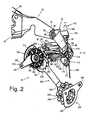
Fig. 2 is a laterally inner view of the derailleur; -
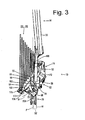
Fig. 3 is a top view of the derailleur in the high speed position; -
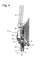
Fig. 4 is a bottom view of the derailleur in the high speed position; -
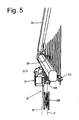
Fig. 5 is a front view of the derailleur in the high speed position; -
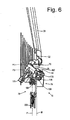
Fig. 6 is a rear view of the derailleur in the high speed position; -
Fig. 7 is a side view of the derailleur in a low speed position; -
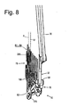
Fig. 8 is a top view of the derailleur in the low speed position; -
Fig. 9 is a bottom view of the derailleur in the low speed position; -
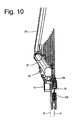
Fig. 10 is a front view of the derailleur in the low speed position; -
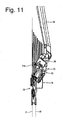
Fig. 11 is a rear view of the derailleur in the low speed position; and -
Fig. 12 is a laterally outer view of the rear derailleur attached to a conventional frame. -
Figs. 1-11 are various views of a particular embodiment of alow profile derailleur 10 in various positions. For example,Fig. 1 is a laterally outer view ofrear derailleur 10, andFig. 2 is a rear view ofderailleur 10. As shown inFig. 1 ,rear derailleur 10 is attached to the rear portion of abicycle frame 14 for guiding achain 18 among a plurality of rear sprockets R1-R8 that rotate coaxially around arear wheel axle 22 supported to frame 14, whereinaxle 22 defines a rotational axis X. -
Bicycle frame 14 is part of an overall bicycle frame that includes achain stay 26, aseat stay 30 and a frame end 34 (commonly referred to as a dropout) that joins chain stay 26 and seat stay 26 together, typically by weldingchain stay 26 and seat stay 30 to frameend 34. Conceptually, each of these frame structures is well known. However, this embodiment employs a configuration offrame end 34 that differs from common frame ends. More specifically,frame end 34 comprises aforward portion 38 and arearward portion 42, whereinforward portion 38 extends fromchain stay 26 and seat stay 30 to a horizontal position aligned with rotational axis X, andrearward portion 42 extends from the horizontal position aligned with rotational axis X rearward. A junction betweenforward portion 38 andrearward portion 42 forms anaxle receiving slot 46 dimensioned to receiverear axle 22 therein. In this embodiment,axle receiving slot 46 is oriented substantially vertical with a slight incline and includes anopen end 50 and aclosed end 54, whereinopen end 50 is disposed belowclosed end 54.Rearward portion 42 extends rearward and downward at an incline and forms a derailleur attachment structure in the form of a laterally projecting annular mountingboss 58 with anopening 60 dimensioned to receive aderailleur mounting bolt 62 therein. Of course, in someembodiments mounting boss 58 need no project laterally, in which case the surface of opening 60 forms the derailleur attachment structure. In this embodiment, opening 60 may be located from approximately 180° to approximately 240° relative to rotational axis X, or, to facilitate measurement independently ofaxle 22, from approximately 180° to approximately 240° relative toclosed end 54 ofaxle receiving slot 46.Rearward portion 42 offrame end 34 extends further rearward from mountingboss 58 to form aposition setting abutment 66 that functions in a manner discussed below. -
Derailleur 10 comprises abase member 70, amovable member 74 that supports achain guide 78, and alinking mechanism 82 coupled betweenbase member 70 andmovable member 74 so that chain guide 78 moves laterally relative tobase member 70. As best seen inFigs. 2 and3 ,base member 30 comprises an annular mountingboss 86 with a mountingsurface 90 that faces laterally outward to face mountingboss 58 onframe end 34, atransition portion 94 that extends rearward and downward at an incline from mountingboss 86, and alink coupling portion 98 disposed at a lower end portion ofextension portion 94. - As best seen in
Figs. 1 and3 , anadjuster mounting boss 99 extends rearward and then laterally outward from mountingboss 86. A laterally outer portion ofadjuster mounting boss 99 includes an adjuster mounting structure in the form a threadedopening 100 dimensioned to threadingly engage an adjuster in the form of an adjustingscrew 101. The tip of adjustingscrew 101 abuts againstposition setting abutment 66 onframe end 34. Thus, the rotational position betweenframe end 34 andbase member 70 may be adjusted simply by rotating adjustingscrew 101. - An
outer casing coupler 102 in the form of a hollow cylinder is disposed on an upper portion oftransition portion 94, whereinouter casing coupler 102 is dimensioned to couple to and terminate anouter casing 106 of aBowden cable 110 in a known manner.Outer casing coupler 102 is positioned to be located rearward from rotational axis X and, more particularly, rearward fromframe end 34 and at least partially laterally inward from mountingsurface 90 ofbase member 70 as shown inFig. 3 .Outer casing coupler 102 includes an outercasing receiving bore 104 having a bore axis B that is inclined relative to a pulley plane, or main central plane P described below. If desired, a cable adjusting bolt (not shown), the concept and structures of which are well known, may be mounted in outercasing receiving bore 104 so as to be disposed betweenouter casing coupler 102 andouter casing 106. - As shown in
Figs. 1 and2 ,link coupling portion 98 includes asupport wall 114, an outerlink mounting ear 118 and an innerlink mounting ear 122. In this embodiment, innerlink mounting ear 122 is formed as an extension oftransition portion 94 that inclines laterally inwardly from front to rear and from top to bottom,support wall 114 extends laterally outwardly from inner mountingear 122 so as to incline rearwardly from top to bottom and fromtransition portion 94 to the laterally outer end, and outerlink mounting ear 118 extends downwardly fromsupport wall 114 so as to incline laterally inwardly from front to rear and from top to bottom. -
Movable member 74 comprises a main body 130 and a link mounting frame 134. In this embodiment, main body 130 comprises a generally cylindrical member that houses atorsion coil spring 138, one end of which is inserted into aspring mounting opening 142 formed in a laterallyouter side wall 146 of main body 130. Link mounting frame 134 comprises an upperlink mounting boss 150, a lowerlink mounting boss 154, and an upper chain guidelink mounting frame 158, all of which are formed as one piece with main body 130. - Linking
mechanism 82 comprises linking members in the form of a laterally outerupper link 162 and a laterally innerlower link 166. A first end ofupper link 162 is straddled bylink coupling portion 98 ofbase member 70 and is pivotably connected thereto by apivot shaft 170 that defines a pivot axis P1. The second end ofupper link 162 is forked to straddle upperlink mounting boss 150 of link mounting frame 134 ofmovable member 74 and is pivotably connected thereto by a pivot shaft 174 that defines a pivot axis P2. Because of this arrangement, a distance between the outermost edges of the first end ofupper link 162 atbase member 70 is less than a distance between the outermost edges of the second end ofupper link 162 atmovable member 74. An outerlimit adjusting screw 186 and an innerlimit adjusting screw 190 are mounted onupper link 162 to adjust the laterally outermost and laterally innermost positions ofmovable member 74, respectively, in a well known manner. - Similarly, a first end of
lower link 166 is straddled bylink coupling portion 98 ofbase member 70 and is pivotably connected thereto by apivot shaft 178 that defines a pivot axis P3. Anactuating arm 175 extends downwardly and laterally inwardly from the first end oflower link 166 so as to generally conform to the inclined contour formed by the outer peripheral surfaces of the plurality of sprockets R1-R8. A cable attachment structure in the form of abolt 176 and a clampingwasher 177 is provided at the outer end of actuatingarm 175 to attach aninner cable 108 ofBowden cable 106 as shown inFig. 2 . As shown inFig. 3 ,bolt 176 andwasher 177 are disposed laterally inward from mountingsurface 90 ofbase member 70 when chain guide 78 is located at a laterally outermost position. -
Lower link 166 is forked beginning in close proximity to pivotshaft 178 to formlegs 179 and 180 (Fig. 2 ) that extend towardmovable member 74.Legs link mounting boss 154 of link mounting frame 134 ofmovable member 74 and is pivotably connected thereto by a pivot shaft 182 (Fig. 1 ) that defines a pivot axis P4. Because of this arrangement, a distance between the outermost edges of the first end oflower link 166 atbase member 70 is less than a distance between the outermost edges of the second end oflower link 166 atmovable member 74. - As shown in
Fig. 2 ,legs lower link 166 receive a coiledreturn spring 181 therebetween. One end ofspring 181 is connected tobase member 70 atpivot shaft 170, and the other end ofspring 181 is connected tomovable member 74 atpivot shaft 182. As a result,spring 181 biasesmovable member 74 laterally outwardly. -
Chain guide 78 comprises an upperchain guide link 194, a first orupper guide pulley 198 rotatably mounted to upper chain guide link 194 through apivot shaft 200, a lowerchain guide link 202, and a second orlower tension pulley 206 rotatably mounted to lower chain guide link 202 through apivot shaft 208. Upperchain guide link 194 is pivotably connected to upper chain guidelink mounting frame 158 through apivot shaft 210. Upperchain guide link 194 comprises achain pushing member 214 and achain regulating unit 218.Chain pushing member 214 is disposed between upper chain guidelink mounting frame 158 and guidepulley 198, with anarcuate portion 222 disposed in close proximity to the teeth onguide pulley 198.Chain pushing member 214 is provided to pushchain 18 when switchingchain 18 from a smaller diameter sprocket to a larger diameter sprocket and to preventchain 18 from derailing fromguide pulley 198.Chain pushing member 214 rotates around a chain pushing member rotational axis defined bypivot shaft 210, which in this embodiment is offset from a first pulley axis defined bypivot shaft 200. As a result, bothguide pulley 198 andchain pushing member 214 rotate around the chain pushing member rotational axis defined bypivot shaft 210. -
Chain regulating unit 218 comprises aninner plate 226, anouter plate 230 and aregulator pin 234. A radially inner end ofinner plate 226 is coupled to pivotshaft 200, and a radially outer end ofinner plate 226 is fastened to one end ofregulator pin 234. A radially inner, portion ofouter plate 230 joins withchain pushing member 214 and is coupled to pivotshaft 210, and a radially outer end ofouter plate 230 is fastened to the other end ofregulator pin 234.Inner plate 226 helps to preventchain 18 from derailing fromguide pulley 198 when switchingchain 18 from a larger diameter sprocket to a smaller diameter sprocket, andouter plate 230 helps to preventchain 18 from derailing fromguide pulley 198 when switchingchain 18 from a smaller diameter sprocket to a larger diameter sprocket.Regulator pin 234 helps to prevent excessive radial movement ofchain 18 and ensures that upperchain guide link 194 rotates counterclockwise aroundpivot shaft 210 in response to forward swinging ofchain 18. However,chain regulating unit 218 may be omitted in some embodiments. - As shown in
Fig. 2 , anupper end 205 of lowerchain guide link 202 is pivotably coupled to main body 130 ofmovable member 74 through apivot shaft 238 and includes a plurality of, e.g., threespring coupling openings 242. The other end ofspring 138 mentioned above is inserted into one of thespring coupling openings 242 to set a desired biasing force on lowerchain guide link 202. As a result, lowerchain guide link 202 is biased clockwise inFig. 1 . Alower end 207 of lower chain guide link 202 rotatably supportstension pulley 206 throughpivot shaft 208 and nonrotatably supports achain regulating unit 248. In this embodiment, as shown inFig. 4 ,upper end 205 is substantially vertically straight and is laterally inwardly offset relative tolower end 207, which also is substantially vertically straight. As withchain regulating unit 218,chain regulating unit 248 comprises aninner plate 252, anouter plate 256 and aregulator pin 260. A radially inner end ofinner plate 252 is coupled to pivotshaft 208, and a radially outer end ofinner plate 252 is fastened to one end ofregulator pin 260. In this embodiment,outer plate 256 is formed as a part of lowerchain guide link 202 and supportspivot shaft 208. A radially outer end ofouter plate 256 is fastened to the other end ofregulator pin 260.Inner plate 252 helps to preventchain 18 from derailing fromtension pulley 206 when switchingchain 18 from a larger diameter sprocket to a smaller diameter sprocket, andouter plate 256 helps to preventchain 18 from derailing fromtension pulley 206 when switchingchain 18 from a smaller diameter sprocket to a larger diameter sprocket.Regulator pin 260 helps to prevent excessive radial movement ofchain 18.Chain regulating unit 248 may be omitted in some embodiments. - In this embodiment,
base member 70,movable member 74,chain guide 78 and linkingmechanism 82 are dimensioned so thatguide pulley 198 is located at a range of from approximately 220° to approximately 270° relative to rotational axis X when chain guide 78 is disposed in the laterally outermost position. - As shown in
Fig. 4 , guidepulley 198 has a pulley plane or main central plane P that bisectsguide pulley 198. In this embodiment, each tooth onguide pulley 198 is symmetrical and centered on the pulley when viewed perpendicular to pivotshaft 200 so that pulley plane P is located in the center ofguide pulley 198, and all of the pulley teeth lie in pulley plane P. In this embodiment, pulley plane P also bisectstension pulley 206. In order to provide a decreased laterally outward profile forderailleur 10, the components are structured so that pulley plane P intersects at least one ofupper link 162 orlower link 166 when chain guide 78 is disposed in a position somewhere between a laterally outermost rest position and a laterally innermost position (such as the laterally outermost position shown inFig. 4 ). - As used throughout herein, the word "intersect" has the ordinary meaning of having one or more points in common. Thus, the term also includes, for example, a tangent relationship. The laterally outermost position may be the laterally outermost position when
derailleur 10 is removed from the bicycle. In this case, the laterally outermost position may be determined by the position ofchain guide 78 with the derailleur at rest and subjected only to the biasing force ofreturn spring 181, and the laterally innermost position is determined by the position ofchain guide 78 when chain guide 78 is manually pulled to its laterally innermost position. Alternatively, the laterally outermost position may be determined by the position ofchain guide 78 when it is set to be aligned with the smallest diameter rear sprocket Ri, and the laterally innermost position may be determined by the position ofchain guide 78 when it is set to be aligned with the largest diameter rear sprocket R8. The word "between" is used in an inclusive sense. - Furthermore, in this embodiment, pulley plane P intersects at least one of pivot axis P1 or pivot axis P3 when measured across all components at the coupling when chain guide 78 is disposed in a position somewhere between a laterally outermost rest position and a laterally innermost position (such as the laterally outermost position shown in
Fig. 6 ). For example,pivot shaft 170 defines pivot axis P1 and couplesupper link 162 tobase member 70. The laterally outer tip ofpivot shaft 170 is exposed at outerlink mounting member 118, whereas the laterally inner tip ofpivot shaft 170 is inserted into a blind bore (not shown) in innerlink mounting member 122 so that the inner lateral tip is not exposed at innerlink mounting member 122. The length of pivot axis P1 measured across all components at the coupling therefore extends from the laterally outer tip ofpivot shaft 170 at pivot axis P1 to the laterally inner surface of innerlink mounting member 122 at pivot axis P1. Similarly,pivot shaft 178 defines pivot axis P3 and coupleslower link 166 tobase member 70. The laterally outer tip ofpivot shaft 178 is exposed at outerlink mounting member 118, whereas the laterally inner tip ofpivot shaft 178 is inserted into a blind bore (not shown) in innerlink mounting member 122 so that the inner lateral tip is not exposed at innerlink mounting member 122. The length of pivot axis P3 measured across all components at the coupling therefore extends from the laterally outer tip ofpivot shaft 178 at pivot axis P3 to the laterally inner surface of innerlink mounting member 122 at pivot axis P3. - In this embodiment, pulley plane P intersects both
upper link 162 andlower link 166 as well as pivot axes P1 and P3 when chain guide 78 is disposed in a position somewhere between the laterally outermost position and the laterally innermost position, such as the laterally outermost position shown inFig. 4 . However, it is not necessary to intersect all recited components at all lateral positions ofchain guide 78. For example, while at least one of pivot axes P1-P4 is disposed on a laterally inner side of pulley plane P, and at least one of pivot axes P1-P4 is disposed on a laterally outer side of pulley plane P, in this embodiment second pivot axis P2 as measured according to the definition above is disposed entirely on the laterally outer side of pulley plane P (as well as movable member plane M) in the position shown inFig. 3 . In this embodiment, pulley plane P intersects a space S1 between any facing surfaces (e.g., surfaces 261 and 262 shown inFig. 2 ) ofupper link 162 andlower link 166 as shown inFig. 4 . Pulley plane P also intersectsbase member 70 when chain guide 78 is disposed in a position somewhere between the laterally outermost position and the laterally innermost position, such as the laterally outermost position shown inFig. 3 . - As shown further in
Fig. 4 (withspring 181 removed for clarity), a movable member plane M (or simply called a plane M) that is substantially parallel to pulley plane P intersects aninnermost surface 264 ofmovable member 74. In this embodiment, movable member plane M is parallel to pulley plane P at a laterally innermost edge of the movable member andinnermost surface 264 is coplanar with movable member plane M, although other configurations are possible sincemovable member 74 may have many different shapes. Movable member plane M intersects bothupper link 162 andlower link 166, pivot axes P 1 and P3, and the space S1 between facing surfaces ofupper link 162 and lower link 16 when chain guide 78 is disposed in a position somewhere between the laterally outermost position and the laterally innermost position. Furthermore, at least a portion of a space S2 between movable member plane M and pulley plane P intersects the space S 1 between facing surfaces ofupper link 162 and lower link 16 when chain guide 78 is disposed in a position somewhere between the laterally outermost position and the laterally innermost position, such as the laterally outermost position shown inFig. 4 . In other words, the space S2 at least partially coincides with the space S1 circumscribed by thebase member 70, themovable member 74 and thelinking mechanism 82 when chain guide 78 is disposed in a position somewhere between the laterally outermost position and the laterally innermost position, such as the laterally outermost position shown inFig. 4 - As shown in
Figs. 3 and8 ,derailleur 10 has a very low lateral profile. For example, when chain guide 78 is located in the laterally outermost position shown inFig. 3 , the components barely protrude laterally outward relative to frame 14.Actuating arm 175 and portions of linkingmechanism 82 are disposed laterally inward from pulley plane P and movable member plane M and follow the diagonal contour of sprockets R1-R8, thereby forming a very compact structure. When chain guide 78 is located in the laterally innermost position shown inFig. 8 , mountingboss 58 is the laterally outermost portion ofderailleur 10. In fact, mountingboss 58 does not even protrude laterally outward relative to chain stay 26 orseat stay 30. In this position, actuatingarm 175 and linkingmechanism 82 again following the diagonal contour of sprockets R1-R8. - Prior art derailleurs do not have the ability to have such a low profile. One reason is that the chain guide in prior art derailleurs has a chain pushing member that is formed as one piece with an inner plate that extends from the upper guide pulley to the lower tension pulley, and this inner plate limits the ability of the chain guide to move laterally outwardly. In the presently disclosed embodiment,
chain pushing member 214 is dimensioned to as not to interfere with the ability ofchain guide 78 to move laterally outwardly. The two-piece structure ofchain guide 78 further facilitates such lateral movement. Furthermore, the base member and linking mechanism in prior art derailleurs are dimensioned to be mounted substantially below, or even in front of, the rotational axis X of the rear wheel, and this requires sufficient lateral spacing to ensure that the linking mechanism does not strike the sprockets during operation. Sincebase member 70,upper link 162,lower link 166movable member 74 and chain guide 78 in the presently disclosed embodiment are dimensioned so thatguide pulley 198 is located at a range of from approximately 220° to approximately 270° relative to rotational axis X when chain guide 78 is disposed in the laterally outermost position, the lateral distance required for the components further decreases because the linking mechanism is able to more closely follow the contour formed by the outer peripheral surfaces of the plurality of sprockets R1-R8. Of course, while many of the features described herein contribute to a markedly low profile derailleur, not all features are required, depending upon the application. -
Fig. 12 is a laterally outer view ofrear derailleur 10 mounted to aframe end 300 of a conventional frame 14'. In this case,frame end 300 comprises aforward portion 304 and arearward portion 308, whereinforward portion 304 extends fromchain stay 26 and seat stay 30 to a horizontal position aligned with rotational axis X, andrearward portion 308 extends from a horizontal position aligned with rotational axis X rearwardly and substantially vertically downwardly. A junction betweenforward portion 304 andrearward portion 308 forms an axle receiving slot 312 dimensioned to receiverear axle 22 therein. In this embodiment, axle receiving slot 312 again is oriented substantially vertically with a slight incline and defines anopen end 316 and aclosed end 320, whereinopen end 316 is disposed belowclosed end 320.Rearward portion 308 forms anannular mounting boss 324 with an opening (not shown) dimensioned to receive a mounting bolt 328 therein. -
Derailleur 10 is mounted to anextension member 330 having afirst end portion 334 and asecond end portion 338, whereinfirst end portion 334 includes a mountingopening 342 dimensioned for receiving mountingbolt 346 therein.Second end portion 338 includes a derailleur attachment structure in the form of aderailleur mounting opening 350 dimensioned for receiving mountingbolt 62 therethrough.Extension member 330 is dimensioned such that, whenextension member 330 is attached to frameend 300, mountingopening 350, and henceboss member 86 ofbase member 70 ofderailleur 10, is located from approximately 180° to approximately 240° relative to axle receiving opening 312, from approximately 180° to approximately 240° relative to rotational axis X, or, to facilitate measurement independently ofaxle 22, from approximately 180° to approximately 240° relative toclosed end 320 of axle receiving opening 312.Rearward portion 38 extends further rearwardly fromderailleur mounting opening 350 to form aposition setting abutment 354 that functions in the same manner asposition setting abutment 66 in the first embodiment. - While the above is a description of various embodiments of inventive features, further modifications may be employed without departing from the scope of the present invention. For example, the size, shape, location or orientation of the various components may be changed as desired. Components that are shown directly connected or contacting each other may have intermediate structures disposed between them. The functions of one element may be performed by two, and vice versa. The function of one element may be performed by another, and functions may be interchanged among the elements. The structures and functions of one embodiment may be adopted in another embodiment. It is not necessary for all advantages to be present in a particular embodiment at the same time. Every feature which is unique from the prior art, alone or in combination with other features, also should be considered a separate description of further inventions by the applicant, including the structural and/or functional concepts embodied by such feature(s). Thus, the scope of the invention should not be limited by the specific structures disclosed or the apparent initial focus or emphasis on a particular structure or feature.
Claims (10)
- A bicycle rear derailleur comprising
a base member (70),
a movable member (74) that supports a chain guide (78) including a first pulley that rotates around a first pulley axis, wherein the pulley has a pulley plane (P); and
a first linking member coupled between the base member (70) and the movable member (74) so that the chain guide moves laterally relative to the base member (70) between a first lateral position and a second lateral position;
a second linking member coupled between the base member (70) and the movable member (74) so that the chain guide (78) moves laterally relative to the base member (70) between a first lateral position and a second lateral position;
wherein the first linking member (162, 166) is coupled to the base member (70) for pivoting around a first pivot axis (P1, P3) that extend across all components at the coupling of the first linking member and the base member;
wherein the first linking member (162, 166) is coupled to the movable member (74) for pivoting around a second pivot axis (P2, P4) that extend across all components at the coupling of the first linking member and the movable member,
wherein the pulley plane (P) intersects the first pivot axis when the chain guide is located at a first position between the first lateral position and the second lateral position, such that a space circumscribed by the base member, the movable member and the linking members (162, 166) coincides at least in part with a space between a plane being parallel to said the pulley plane at an innermost edge of the movable member, and the pulley plane in at least one position of the pulley,
and wherein at least a portion of the first pivot axis is disposed on a laterally inner side of the pulley plane and wherein at least a portion of the second pivot axis is disposed on a laterally outer side of the pulley plane
characterized in that
the base member (70) is structured to be mounted to a rear frame end, ,wherein a first width of the first linking member at the first pivot location is different from a second width of the first linking member at the second pivot location,
the first linking member straddling one of the base member or the movable member, and the first linking member being straddled by the other one of the base member or the movable member. - The derailleur according to claim 1 further comprising a biasing member that biases the chain guide (78) so that the chain guide is set at the first lateral position, wherein the pulley plane (P) intersects the first pivot axis when the chain guide is located at the first lateral position.
- The derailleur according to claim 1 or 2, wherein the first lateral position is a laterally outermost position of the chain guide.
- The derailleur according to anyone of claims I to 3, wherein a movable member plane intersects an innermost surface of the movable member (74) and is oriented substantially parallel to the pulley plane (P), and wherein the movable member plane intersects the first pivot axis when the chain guide is located at the first lateral position.
- The derailleur according to anyone of claims 1 to 4, wherein at least a portion of the first pivot axis is disposed on a laterally inner side of the pulley plane.
- The derailleur according to anyone of claims 1 to 5, wherein the pulley plane (P) intersects the first linking member when the chain guide is located at a first position between the first lateral position and the second lateral position.
- The derailleur according to anyone of claims 1 to 6, further comprising a second linking member (162) coupled between the base member and the movable member so that the chain guide moves laterally between the first lateral position and the second lateral position, wherein the second lateral position is disposed laterally outward from the first linking member.
- The derailleur according to claim 7, wherein the pulley plane intersects the second linking member when the chain guide is located at a second position between the first lateral position and the second lateral position.
- The derailleur according to claim 7 or 8, wherein the pulley plane intersects a space between the first linking member and the second linking member when the chain guide is located at the first position.
- The derailleur according to claim 9, wherein a movable member plane (M) intersects an innermost surface of the movable member and is oriented substantially parallel to the pulley plane, and wherein at least a portion of a space between the pulley plane and the movable member plane intersects the space between the first linking member and the second linking member.
Priority Applications (1)
| Application Number | Priority Date | Filing Date | Title |
|---|---|---|---|
| EP10183792A EP2301835A1 (en) | 2006-02-28 | 2006-02-28 | Bicycle rear end structure |
Applications Claiming Priority (1)
| Application Number | Priority Date | Filing Date | Title |
|---|---|---|---|
| EP20060004024 EP1826114B1 (en) | 2006-02-28 | 2006-02-28 | Assembly of a bicycle frame and a low profile derailleur |
Related Parent Applications (2)
| Application Number | Title | Priority Date | Filing Date |
|---|---|---|---|
| EP06004024.3 Division | 2006-02-28 | ||
| EP20060004024 Division EP1826114B1 (en) | 2006-02-28 | 2006-02-28 | Assembly of a bicycle frame and a low profile derailleur |
Related Child Applications (1)
| Application Number | Title | Priority Date | Filing Date |
|---|---|---|---|
| EP10183792.0 Division-Into | 2010-09-30 |
Publications (2)
| Publication Number | Publication Date |
|---|---|
| EP2000399A1 EP2000399A1 (en) | 2008-12-10 |
| EP2000399B1 true EP2000399B1 (en) | 2011-09-28 |
Family
ID=36563616
Family Applications (4)
| Application Number | Title | Priority Date | Filing Date |
|---|---|---|---|
| EP06022723A Active EP1829780B1 (en) | 2006-02-28 | 2006-02-28 | Derailleur |
| EP20060004024 Revoked EP1826114B1 (en) | 2006-02-28 | 2006-02-28 | Assembly of a bicycle frame and a low profile derailleur |
| EP08161785A Revoked EP2000399B1 (en) | 2006-02-28 | 2006-02-28 | Derailleur |
| EP10183792A Withdrawn EP2301835A1 (en) | 2006-02-28 | 2006-02-28 | Bicycle rear end structure |
Family Applications Before (2)
| Application Number | Title | Priority Date | Filing Date |
|---|---|---|---|
| EP06022723A Active EP1829780B1 (en) | 2006-02-28 | 2006-02-28 | Derailleur |
| EP20060004024 Revoked EP1826114B1 (en) | 2006-02-28 | 2006-02-28 | Assembly of a bicycle frame and a low profile derailleur |
Family Applications After (1)
| Application Number | Title | Priority Date | Filing Date |
|---|---|---|---|
| EP10183792A Withdrawn EP2301835A1 (en) | 2006-02-28 | 2006-02-28 | Bicycle rear end structure |
Country Status (2)
| Country | Link |
|---|---|
| EP (4) | EP1829780B1 (en) |
| DE (1) | DE602006014793D1 (en) |
Families Citing this family (5)
| Publication number | Priority date | Publication date | Assignee | Title |
|---|---|---|---|---|
| TW201641348A (en) * | 2015-05-20 | 2016-12-01 | Zhan Zhi Green Energy Co Ltd | Stepping-back reversing driving device of multi-speed transmission tricycle |
| DE102018001253A1 (en) | 2017-03-20 | 2018-09-20 | Sram Deutschland Gmbh | Rear derailleur for coaxial mounting |
| US10501147B2 (en) * | 2017-08-22 | 2019-12-10 | Shimano Inc. | Bicycle derailleur |
| US10981626B2 (en) | 2018-03-20 | 2021-04-20 | Sram Deutschland Gmbh | Drive arrangement for a bicycle |
| DE102020201229A1 (en) | 2019-03-22 | 2020-09-24 | Sram Deutschland Gmbh | Coaxial switchgear connection |
Family Cites Families (22)
| Publication number | Priority date | Publication date | Assignee | Title |
|---|---|---|---|---|
| BE425459A (en) * | ||||
| US534680A (en) * | 1895-02-26 | Ments | ||
| FR760565A (en) * | 1933-08-26 | 1934-02-26 | Speed change for cycles | |
| FR799947A (en) * | 1935-03-27 | 1936-06-23 | Chain derailleur tensioner for bicycles | |
| FR869777A (en) | 1941-02-05 | 1942-02-16 | Derailleur for bicycles and, in general, for any chain transmission device | |
| CH284668A (en) * | 1950-08-23 | 1952-07-31 | Trost Ernst | Changing device for a chain transmission on a bicycle. |
| FR2314093A1 (en) * | 1975-06-12 | 1977-01-07 | Huret Roger | DERAILLEUR FOR BICYCLE |
| JPS591901Y2 (en) * | 1979-02-15 | 1984-01-19 | 株式会社シマノ | rear derailleur |
| JPS6015516B2 (en) * | 1979-12-19 | 1985-04-19 | 株式会社シマノ | bicycle derailleur |
| EP0032049A3 (en) * | 1979-12-29 | 1982-10-27 | Shimano Industrial Company Limited | Cycle derailleur and use thereof |
| US4437848A (en) * | 1980-03-15 | 1984-03-20 | Shimano Industrial Company Limited | Derailleur for a bicycle |
| US4443208A (en) * | 1980-12-16 | 1984-04-17 | Bridgestone Cycle Co. Ltd. | Speed-change gear mounted outside a bicycle |
| JPH0671916B2 (en) * | 1984-12-29 | 1994-09-14 | 島野工業株式会社 | Bicycle dealer |
| DE4022473C2 (en) * | 1990-07-14 | 1994-01-20 | Rolf Dr Meissner | Derailleur for a bicycle |
| EP0513394B1 (en) | 1990-12-08 | 1995-09-27 | Mory Suntour Inc. | Change gear mechanism for bicycle |
| JPH0820375A (en) * | 1991-11-11 | 1996-01-23 | Mori San Tour:Kk | Speed change mechanis for bicycle |
| DE9422229U1 (en) | 1993-02-03 | 1999-04-08 | Shimano Kk | Rear derailleur for a bicycle |
| JP3372616B2 (en) * | 1993-11-30 | 2003-02-04 | 株式会社シマノ | Bicycle derailleur |
| US5456637A (en) * | 1994-10-07 | 1995-10-10 | Chang; Shu-Gen | Chain shifting device for bicycle |
| DE19915334A1 (en) * | 1999-04-03 | 2000-10-05 | Sram De Gmbh | Cable guide system for derailleur for bicycles has deflection pulley with two different curved cable tracks for cable deflection through more than 120o to improve efficiency |
| US6287228B1 (en) * | 1999-11-12 | 2001-09-11 | Shimano, Inc. | Rear derailleur with cable guide roller |
| US6354971B1 (en) * | 2000-02-02 | 2002-03-12 | Brigham Young University | Compliant derailleur |
-
2006
- 2006-02-28 DE DE200660014793 patent/DE602006014793D1/en active Active
- 2006-02-28 EP EP06022723A patent/EP1829780B1/en active Active
- 2006-02-28 EP EP20060004024 patent/EP1826114B1/en not_active Revoked
- 2006-02-28 EP EP08161785A patent/EP2000399B1/en not_active Revoked
- 2006-02-28 EP EP10183792A patent/EP2301835A1/en not_active Withdrawn
Also Published As
| Publication number | Publication date |
|---|---|
| DE602006014793D1 (en) | 2010-07-22 |
| EP1826114B1 (en) | 2010-06-09 |
| EP2000399A1 (en) | 2008-12-10 |
| EP1829780B1 (en) | 2010-10-27 |
| EP2301835A1 (en) | 2011-03-30 |
| EP1826114A1 (en) | 2007-08-29 |
| EP1829780A1 (en) | 2007-09-05 |
Similar Documents
| Publication | Publication Date | Title |
|---|---|---|
| US8012052B2 (en) | Low profile rear derailleur with cable guide | |
| US8277346B2 (en) | Low profile rear derailleur | |
| EP1939085B1 (en) | Low profile rear derailleur with a chain receiving space | |
| EP2078668B2 (en) | Low profile rear derailleur | |
| JP3373195B2 (en) | Bicycle derailleur assembly | |
| EP1632429B1 (en) | Bicycle rear derailleur | |
| EP2000399B1 (en) | Derailleur | |
| CN101704400A (en) | Low outline rear derailleur | |
| CZ20004178A3 (en) | Rear derailleur with cable guide roller |
Legal Events
| Date | Code | Title | Description |
|---|---|---|---|
| PUAI | Public reference made under article 153(3) epc to a published international application that has entered the european phase |
Free format text: ORIGINAL CODE: 0009012 |
|
| AC | Divisional application: reference to earlier application |
Ref document number: 1826114 Country of ref document: EP Kind code of ref document: P |
|
| AK | Designated contracting states |
Kind code of ref document: A1 Designated state(s): AT BE BG CH CY CZ DE DK EE ES FI FR GB GR HU IE IS IT LI LT LU LV MC NL PL PT RO SE SI SK TR |
|
| 17P | Request for examination filed |
Effective date: 20090610 |
|
| AKX | Designation fees paid |
Designated state(s): DE FR IT NL |
|
| 17Q | First examination report despatched |
Effective date: 20100316 |
|
| GRAP | Despatch of communication of intention to grant a patent |
Free format text: ORIGINAL CODE: EPIDOSNIGR1 |
|
| GRAS | Grant fee paid |
Free format text: ORIGINAL CODE: EPIDOSNIGR3 |
|
| GRAA | (expected) grant |
Free format text: ORIGINAL CODE: 0009210 |
|
| AC | Divisional application: reference to earlier application |
Ref document number: 1826114 Country of ref document: EP Kind code of ref document: P |
|
| AK | Designated contracting states |
Kind code of ref document: B1 Designated state(s): DE FR IT NL |
|
| REG | Reference to a national code |
Ref country code: DE Ref legal event code: R096 Ref document number: 602006024772 Country of ref document: DE Effective date: 20111201 |
|
| REG | Reference to a national code |
Ref country code: NL Ref legal event code: VDEP Effective date: 20110928 |
|
| PG25 | Lapsed in a contracting state [announced via postgrant information from national office to epo] |
Ref country code: NL Free format text: LAPSE BECAUSE OF FAILURE TO SUBMIT A TRANSLATION OF THE DESCRIPTION OR TO PAY THE FEE WITHIN THE PRESCRIBED TIME-LIMIT Effective date: 20110928 |
|
| PLBI | Opposition filed |
Free format text: ORIGINAL CODE: 0009260 |
|
| PLAX | Notice of opposition and request to file observation + time limit sent |
Free format text: ORIGINAL CODE: EPIDOSNOBS2 |
|
| 26 | Opposition filed |
Opponent name: SRAM DEUTSCHLAND GMBH Effective date: 20120627 |
|
| REG | Reference to a national code |
Ref country code: DE Ref legal event code: R026 Ref document number: 602006024772 Country of ref document: DE Effective date: 20120627 |
|
| PLAF | Information modified related to communication of a notice of opposition and request to file observations + time limit |
Free format text: ORIGINAL CODE: EPIDOSCOBS2 |
|
| PLBB | Reply of patent proprietor to notice(s) of opposition received |
Free format text: ORIGINAL CODE: EPIDOSNOBS3 |
|
| PLAY | Examination report in opposition despatched + time limit |
Free format text: ORIGINAL CODE: EPIDOSNORE2 |
|
| PLBC | Reply to examination report in opposition received |
Free format text: ORIGINAL CODE: EPIDOSNORE3 |
|
| PGFP | Annual fee paid to national office [announced via postgrant information from national office to epo] |
Ref country code: FR Payment date: 20140211 Year of fee payment: 9 |
|
| PLAB | Opposition data, opponent's data or that of the opponent's representative modified |
Free format text: ORIGINAL CODE: 0009299OPPO |
|
| R26 | Opposition filed (corrected) |
Opponent name: SRAM DEUTSCHLAND GMBH Effective date: 20120627 |
|
| PGFP | Annual fee paid to national office [announced via postgrant information from national office to epo] |
Ref country code: DE Payment date: 20150224 Year of fee payment: 10 |
|
| RDAF | Communication despatched that patent is revoked |
Free format text: ORIGINAL CODE: EPIDOSNREV1 |
|
| APAH | Appeal reference modified |
Free format text: ORIGINAL CODE: EPIDOSCREFNO |
|
| APBM | Appeal reference recorded |
Free format text: ORIGINAL CODE: EPIDOSNREFNO |
|
| APBP | Date of receipt of notice of appeal recorded |
Free format text: ORIGINAL CODE: EPIDOSNNOA2O |
|
| REG | Reference to a national code |
Ref country code: DE Ref legal event code: R103 Ref document number: 602006024772 Country of ref document: DE Ref country code: DE Ref legal event code: R064 Ref document number: 602006024772 Country of ref document: DE |
|
| APBU | Appeal procedure closed |
Free format text: ORIGINAL CODE: EPIDOSNNOA9O |
|
| RDAG | Patent revoked |
Free format text: ORIGINAL CODE: 0009271 |
|
| STAA | Information on the status of an ep patent application or granted ep patent |
Free format text: STATUS: PATENT REVOKED |
|
| 27W | Patent revoked |
Effective date: 20150924 |
|
| REG | Reference to a national code |
Ref country code: FR Ref legal event code: ST Effective date: 20151030 |
|
| PG25 | Lapsed in a contracting state [announced via postgrant information from national office to epo] |
Ref country code: FR Free format text: LAPSE BECAUSE OF NON-PAYMENT OF DUE FEES Effective date: 20150302 |
|
| PGFP | Annual fee paid to national office [announced via postgrant information from national office to epo] |
Ref country code: IT Payment date: 20160222 Year of fee payment: 11 |