EP4219084B1 - Outil de travail portatif - Google Patents
Outil de travail portatif Download PDFInfo
- Publication number
- EP4219084B1 EP4219084B1 EP22154068.5A EP22154068A EP4219084B1 EP 4219084 B1 EP4219084 B1 EP 4219084B1 EP 22154068 A EP22154068 A EP 22154068A EP 4219084 B1 EP4219084 B1 EP 4219084B1
- Authority
- EP
- European Patent Office
- Prior art keywords
- handle
- front handle
- functional element
- implement according
- housing
- Prior art date
- Legal status (The legal status is an assumption and is not a legal conclusion. Google has not performed a legal analysis and makes no representation as to the accuracy of the status listed.)
- Active
Links
Images


Classifications
-
- H—ELECTRICITY
- H05—ELECTRIC TECHNIQUES NOT OTHERWISE PROVIDED FOR
- H05B—ELECTRIC HEATING; ELECTRIC LIGHT SOURCES NOT OTHERWISE PROVIDED FOR; CIRCUIT ARRANGEMENTS FOR ELECTRIC LIGHT SOURCES, IN GENERAL
- H05B3/00—Ohmic-resistance heating
- H05B3/02—Details
-
- B—PERFORMING OPERATIONS; TRANSPORTING
- B25—HAND TOOLS; PORTABLE POWER-DRIVEN TOOLS; MANIPULATORS
- B25F—COMBINATION OR MULTI-PURPOSE TOOLS NOT OTHERWISE PROVIDED FOR; DETAILS OR COMPONENTS OF PORTABLE POWER-DRIVEN TOOLS NOT PARTICULARLY RELATED TO THE OPERATIONS PERFORMED AND NOT OTHERWISE PROVIDED FOR
- B25F5/00—Details or components of portable power-driven tools not particularly related to the operations performed and not otherwise provided for
- B25F5/02—Construction of casings, bodies or handles
-
- A—HUMAN NECESSITIES
- A01—AGRICULTURE; FORESTRY; ANIMAL HUSBANDRY; HUNTING; TRAPPING; FISHING
- A01G—HORTICULTURE; CULTIVATION OF VEGETABLES, FLOWERS, RICE, FRUIT, VINES, HOPS OR SEAWEED; FORESTRY; WATERING
- A01G3/00—Cutting implements specially adapted for horticultural purposes; Delimbing standing trees
- A01G3/04—Apparatus for trimming hedges, e.g. hedge shears
- A01G3/047—Apparatus for trimming hedges, e.g. hedge shears portable
- A01G3/053—Apparatus for trimming hedges, e.g. hedge shears portable motor-driven
-
- A—HUMAN NECESSITIES
- A01—AGRICULTURE; FORESTRY; ANIMAL HUSBANDRY; HUNTING; TRAPPING; FISHING
- A01G—HORTICULTURE; CULTIVATION OF VEGETABLES, FLOWERS, RICE, FRUIT, VINES, HOPS OR SEAWEED; FORESTRY; WATERING
- A01G3/00—Cutting implements specially adapted for horticultural purposes; Delimbing standing trees
- A01G3/08—Other tools for pruning, branching or delimbing standing trees
- A01G3/085—Motor-driven saws for pruning or branching
- A01G3/086—Chain saws
-
- H—ELECTRICITY
- H05—ELECTRIC TECHNIQUES NOT OTHERWISE PROVIDED FOR
- H05B—ELECTRIC HEATING; ELECTRIC LIGHT SOURCES NOT OTHERWISE PROVIDED FOR; CIRCUIT ARRANGEMENTS FOR ELECTRIC LIGHT SOURCES, IN GENERAL
- H05B3/00—Ohmic-resistance heating
- H05B3/20—Heating elements having extended surface area substantially in a two-dimensional [2D] plane, e.g. plate-heater
- H05B3/34—Heating elements having extended surface area substantially in a two-dimensional [2D] plane, e.g. plate-heater flexible, e.g. heating nets or webs
-
- B—PERFORMING OPERATIONS; TRANSPORTING
- B27—WORKING OR PRESERVING WOOD OR SIMILAR MATERIAL; NAILING OR STAPLING MACHINES IN GENERAL
- B27B—SAWS FOR WOOD OR SIMILAR MATERIAL; COMPONENTS OR ACCESSORIES THEREFOR
- B27B17/00—Chain saws; Equipment therefor
- B27B17/0008—Means for carrying the chain saw, e.g. handles
Definitions
- the invention relates to a hand-held working device according to the preamble of claim 1.
- Hand-held tools such as chainsaws, hedge trimmers, or similar, are known to be typically used outdoors.
- a hand-held tool is a tool whose intended use is primarily carried by the operator. At particularly low temperatures, the handles of the tool become cold.
- Heated grips are a known method for warming the handles. Heated grips can be electrically connected to a generator or battery in the tool.
- a hand-held tool is in US 2017/165863 A1 revealed.
- the invention is therefore based on the object of providing a hand-held working device that enables reliable operation of an electrical functional element arranged on a handle of the working device.
- the invention is based on the finding that a defect in the above-described functional element located on the handle, such as a handle heater, occurring during operation of the tool is due to a broken connecting cable.
- the connecting cable between the handle heater and the power source for the handle heater runs along the outside of the handle tube and is covered by a handle cover. During use of the tool, branches from bushes, shrubs, or trees, among other things, can brush against the handle, damaging the handle cover and the connecting cable.
- the hand-held tool comprises a housing, wherein the housing has a top side, a bottom side, a first longitudinal side, and a second longitudinal side, wherein the top side and the bottom side are connected to one another via the first longitudinal side and the second longitudinal side.
- the hand-held tool comprises a drive motor arranged in the housing, wherein the drive motor drives a tool arranged at the front end of the housing.
- the hand-held tool comprises a front handle and a rear handle, wherein the front handle is designed as a bow handle and has a transverse section extending along the top side of the housing and a side section extending along one of the two longitudinal sides of the housing.
- the front handle has a wall and an interior space enclosed by the wall, wherein the wall of the front handle comprises an inner side facing the interior space and an outer side facing away from the interior space.
- a first electrical functional element is arranged in the housing.
- At least one second electrical functional element is arranged on the outer side of the front handle.
- the first electrical functional element is connected to the second functional element via at least one connecting cable.
- the at least one connecting cable is arranged at least partially in the interior of the front handle in the region of the side section of the front handle.
- the second electrical functional element is preferably designed as a heating foil.
- the second electrical functional element can also be designed as a sensor.
- the first electrical functional element is preferably an energy source for supplying the second functional element with electrical current.
- the energy source is preferably a generator.
- the energy source can also be a battery.
- the first electrical functional element can alternatively also be a control unit for processing data signals.
- the control unit is supplied with electrical current via an energy source.
- an opening is provided on the wall of the front handle, in particular adjacent to the second electrical functional element, wherein the opening extends from the outside of the wall to the inside of the wall, wherein the at least one connecting cable runs from the outside of the wall through the opening into the interior of the handle.
- the opening is preferably provided with a grommet as edge protection.
- the grommet is preferably formed from an elastomer. This prevents the connecting cable from chafing at the opening.
- the front handle has an approximately horizontally extending holding section, with the opening in the wall being provided outside the holding section.
- the horizontally extending holding section is intended to hold the implement during its intended operation.
- the horizontal gripping section is the area of the front handle that the operator grips most frequently. If the opening were located on the horizontal gripping section, the operator would feel it. The operator might find the opening uncomfortable from an ergonomic point of view. To avoid this, the opening is located outside the horizontal section.
- the transverse section and the side section of the front handle are connected to one another via a curved connecting section, wherein the opening in the side section is provided adjacent to the connecting section.
- An opening in the horizontally running section of the front handle is to be avoided for the reasons already described above.
- the opening should not be formed in the curved connecting section either.
- An opening in the curve would be disadvantageous due to the high stress conditions and the associated weakening of the strength of the front handle.
- the connecting cable should be protected as much as possible by the front handle. Therefore, the opening in the side section is preferably provided directly adjacent to the curved section of the front handle.
- the handle is preferably made of aluminum or plastic.
- the implement comprises a handle tube insert for fastening the front handle to the housing of the implement, wherein the handle tube insert is arranged in the interior of the handle at one end of the front handle.
- the handle tube insert has a cable duct for guiding the at least one connecting cable.
- the handle tube insert can be inserted into the front handle, wherein the connecting cable is guided in the cable duct. This prevents the connecting cable from becoming jammed between the handle tube insert and the handle.
- the handlebar insert has a cable fixation for clamping at least one connecting cable. If the handlebar insert is almost completely inserted into the front handle, the connecting cable can be fixed in the cable fixation. This allows the length of the section of the connecting cable provided in the front handle to be specifically adjusted.
- connection point of the connecting cable to the second functional element is relieved by the clamping on the handlebar insert.
- tensile stress can occur on the connecting cable during assembly of the implement.
- the connecting cable By clamping the connecting cable, the tensile stress is absorbed at the clamping point of the connecting cable.
- the connection between the connecting cable and the second electrical functional element remains undamaged.
- connecting cable it is advantageous for the connecting cable to run from the outside of the front handle wall, through the interior of the front handle, through the connecting channel of the handle tube insert, to one end of the front handle.
- the connecting cable is largely protected from external stresses within the front handle.
- a hand-held tool 1 which is designed as a rear-handle power chainsaw.
- the tool 1 can also be a top-handle power chainsaw.
- the tool can also be designed as a hedge trimmer, power cutter, blower, brush cutter, or the like.
- the tool 1 comprises a housing 2 and a drive motor 3 arranged in the housing 2.
- the drive motor 3 is designed as an internal combustion engine.
- it can be expedient to design the drive motor 3 as an electric motor, which in turn can be supplied with energy via a battery or via a connection cable to a power grid.
- the housing 2 has a top side 26, a bottom side 27, a first longitudinal side 28, and a second longitudinal side 29.
- the top side 26 and the bottom side 27 are connected to one another via the two longitudinal sides 28, 29.
- the working device 1 also comprises a front handle 6 and a rear handle 36.
- the handles 6, 36 serve to hold and guide the working device 1.
- the rear handle is formed at a rear end 31 of the housing 2.
- a saw chain which is driven by the drive motor 3, is arranged circumferentially on the guide rail 4. The saw chain forms the tool 5 of the working device 1.
- the drive motor 3 drives a drive sprocket via a drive shaft (not shown in detail).
- the drive sprocket serves to drive the saw chain, which is guided over the drive sprocket during operation.
- the working device 1 further comprises a tensioning device 21, via which the guide bar 4 can be displaced forwards away from the drive sprocket in the direction of its longitudinal axis 22.
- the longitudinal axis 22 runs centrally through the guide bar 4 approximately parallel to the horizontal floor 51.
- the term "approximately” is to be understood such that the longitudinal axis 22 of the guide bar 4 forms an angle of no more than 15° with the floor 51.
- the guide bar 4 has a longitudinal plane 23, which, when the working device 1 is parked on a flat, horizontal floor 51, contains the longitudinal axis 22 and is perpendicular to the floor 51.
- the front handle 6 is designed as a bow handle.
- the front handle 6 is formed from a handle tube.
- the front handle 6 is preferably made of aluminum or plastic.
- the front handle 6 has a transverse section 32 extending along the top side 26 of the housing 2, a side section 33 extending along the first longitudinal side 28 and a further side section 34 extending along the second longitudinal side 29.
- the front handle 6 is fastened to the housing 2 at the respective ends.
- the end of the first longitudinal side 28 of the front handle 6 is fastened to the side section 33 of the housing 2.
- the other end of the front handle 6 is fastened to the underside 27 of the housing 2.
- a merely schematically illustrated electrical functional element 13 is arranged in the housing 2.
- the electrical functional element 13 is designed as a control unit in the exemplary embodiment.
- the control unit is used to process information and to control various components of the Working device 1, such as the drive motor 3.
- the control unit is supplied with electrical power via a generator provided on the drive motor 3.
- a second electrical functional element 14 is arranged on the front handle 6.
- the second electrical functional element 14 is designed as a heating foil.
- the heating foil serves to heat the front handle 6 and thus forms a handle heater.
- the second electrical functional element 14 can also be designed as a sensor.
- the sensor is preferably designed to detect whether the front handle 6 is grasped by the operator.
- the sensor is preferably a capacitive sensor.
- the second electrical functional element 14 can be designed as a heating foil and a third electrical functional element as a sensor.
- the front handle 6 preferably also comprises a cover 38.
- the cover 38 encloses, in particular, a holding section 16 of the front handle 6.
- the cover 38 is made of a plastic, in particular an elastomer, and serves to fix the second, electrical functional element 14 on the front handle 6. Furthermore, the cover 38 offers the operator a better, more comfortable grip on the front handle 6.
- the working device 1 comprises at least one connecting cable 15, wherein the connecting cable 15 connects the first electrical functional element 13 and the second electrical functional element 14.
- the term "connecting cable” is not limited to a single cable, but also includes multiple cables. Preferably, the cables are connected in series.
- the working device 1 comprises, in addition to the at least one connecting cable 15, a further connecting cable 15'.
- the at least one connecting cable 15 is a first conductor
- the second connecting cable 15' is a second conductor.
- the at least one connecting cable 15 runs from the second electrical functional element 14, designed as a heating foil, to the first electrical functional element 13, the control unit.
- a switch 24 (see also Fig. 8 ) is interposed.
- the second connecting cable 15' is directly connected to the first electrical functional element 13. If the switch 24 is activated, the circuit is closed and the second electrical functional element 14 can be supplied with power. If the switch 24 is deactivated, the power supply is cut off.
- the generator as the first electrical functional element 13.
- the generator is preferably an AC generator.
- the second electrical functional element 14 would be connected to the generator via the connecting cable 15.
- a rectifier is preferably provided between the generator and the second electrical functional element 13.
- the electrical second functional element 14 is arranged on an outer side 12 of the front handle 6.
- the connecting cables 15, 15' run from the second functional element 14 via an opening 8 on the front handle 6 into an interior 10 of the front handle 6.
- the front handle 6 has a wall 7, wherein the wall 7 encloses the interior 10 of the front handle 6. Accordingly, the wall 7 of the front handle 6 comprises an inner side 11 facing the interior 10 and the outer side 12 facing away from the interior 10.
- the opening 8 extends from the outer side 12 of the wall 7 to the inner side 11 of the wall 7.
- the second electrical functional element 14 is arranged on an approximately horizontally extending holding section 16 of the front handle 6.
- the holding section 16 is formed on the transverse section 32 of the front handle 6.
- the holding section 16 is the area of the front handle 6 at which the operator preferably grips the work tool 1 in a working position intended for the work tool.
- the second electrical functional element 14 extends over the transverse section 32 as far as the further longitudinal section 34 of the front handle 6. In an alternative exemplary embodiment, it may be expedient for the second electrical functional element 14 to extend from the further longitudinal section 34 over the transverse section 32 as far as the longitudinal section 33.
- the opening 8 is formed on the side portion 33 of the front handle 6.
- the opening 8 is formed on a side of the front handle 6 facing the housing 2.
- the opening 8 and the connecting cables 15, 15' running along the opening 8 are protected from branches, undergrowth or other objects that may come into contact with the front handle 6 during operation of the implement 1.
- the opening 8 is arranged outside the holding section 16.
- the opening 8 does not interfere with the operator when gripping the holding section 16.
- the opening 8 is arranged on the side section 33 directly adjacent to a connecting section 35 of the front handle 6.
- the connecting section 35 is curved and connects the transverse section 32 and the side section 33 of the front handle 6.
- the opening 8 is located directly below the connecting section 35.
- the opening 8 is preferably provided outside the connecting section 35 for reasons of strength and easier manufacture of the front handle 8.
- the opening 8 as "top” as possible on the side section 33, i.e. adjacent to the connecting section 35, in order to be able to guide the connecting cables 15, 15' in a protected manner over as wide an area as possible in the front handle 6.
- connections of the second electrical functional element 14 for the connecting cables 15, 15' are arranged in the preferred embodiment on the outer side 12 in the connecting section 35. It may also be expedient for the connections of the second electrical functional element 14 for the connecting cables 15, 15' to be arranged on the outer side 12 in the transverse section 32 of the front handle 6.
- the connecting cables 15, 15' run on the outer side 12 of the front handle 6, starting from the connecting section 35, through the opening 8 into the interior 10 of the front handle 6.
- a grommet 9 is provided at the opening 8, with the grommet 9 forming an edge protector at the opening 8. This prevents damage to the connecting cables 15, 15'.
- the connecting cables 15, 15' run from the interior 10 at the opening 8 to an end 20 of the handle 6.
- the connecting cables 15, 15' leave the interior 10 of the front handle 6 at the end 20 of the handle 6.
- the connecting cables 15, 15' run from the end 20 of the front handle 6 along the housing 2 of the working device to the first electrical functional element 13.
- the at least one connecting cable 15 is connected to the first electrical functional element 13 via a switch 24.
- the connecting cables 15, 15' are held on the housing 2 of the working device 1 via a plurality of terminals 37, 37', 37", 37′′′.
- the working device 1 comprises a handle tube insert 17.
- the handle tube insert 17 is preferably made of a metal alloy.
- the handle tube insert 17 serves to fasten the front handle 6 to the housing 2 of the working device 1.
- the handle tube insert 17 is provided at one end 20 of the front handle 6 in the Arranged in the interior space 10 of the front handle 6.
- the handle tube insert 17 comprises a plurality of openings 41, three openings 41 in the preferred embodiment. Of course, it may be expedient to provide fewer or more than three openings in the preferred embodiment.
- the front handle 6 also comprises openings 42 on its side section 33, which, when the handle tube insert 17 is fastened, are coaxial with the openings 41 of the handle tube insert 17.
- the openings 41 of the handle tube insert 17 and the openings 42 of the front handle 6 are designed such that the front handle 6 with the handle tube insert 17 can be fastened to receiving openings in the housing 2 via a plurality of screws 44 projecting through the openings 41, 42.
- the handle tube insert 17 stabilizes the front handle 6, whereby the front handle 6 can be screwed to the housing 2 with a high tightening torque of the screws 44 without deforming.
- the handlebar insert 17 includes a cable duct 18.
- the cable duct 18 serves to guide the connecting cables 15, 15'.
- the cable duct 18 is designed as a groove on the outside of the handlebar insert 17. It may also be expedient to design the cable duct 18 as a bore through the handlebar insert 17.
- the cable duct 18 extends from an upper end 45 of the handle tube insert 17 to a lower end 46 of the handle tube insert 17.
- the handle tube insert 17 extends in its longitudinal direction 47 from the upper end 45 to the lower end 46.
- the longitudinal direction 47 of the handle tube insert 17 corresponds to the insertion direction 48 of the handle tube insert 17 into the front handle 6.
- a cable fixation 19 for clamping the connecting cables 15, 15' is formed on the handle tube insert 17.
- the cable fixation 19 is formed from a further cable duct 49 which adjoins the cable duct 18.
- the further cable duct 49 is formed at an angle to the cable duct 18 of the handle tube insert 17.
- the longitudinal axes of the cable duct 18 of the handle tube insert 17 and the further cable duct 49 of the handle tube insert 17 enclose an angle ⁇ , wherein the angle ⁇ is in a range between 70° and 140°, in particular in a range between 90° and 130°.
- a plurality of lugs 50 are formed on the additional cable duct 49.
- the lugs 50 are arranged alternately on opposite sides of the additional cable duct 49 and protrude at least partially into the additional cable duct 49.
- the connecting cables 15, 15' are held clamped in the additional cable duct 49 by the alternately arranged lugs 50.
- the hand-held tool 1 preferably comprises at least one contact point for connecting the second electrical functional element 14 to the at least one connecting cable 15, 15'.
- the contact point is preferably formed near the opening 8.
- the contact point is preferably provided on the connecting section 35 of the front handle 6.
- the contact point is preferably provided on a side of the connecting section 35 of the front handle 6 facing the housing 2.
- the contact point is preferably designed as a soldered connection in order to keep the exposed cable length of the at least one connecting cable 15, 15' as short as possible.
- the exposed cable length is the section of the at least one connecting cable 15, 15' that is arranged on the outer side 12 of the front handle 6.
- the at least one connecting cable 15, 15' has a concealed cable length that corresponds to the length of the connecting cable 15, 15' from the opening 8 to the end 20 of the front handle 6.
- the exposed cable length corresponds to a maximum of 20%, in particular a maximum of 15%, preferably a maximum of 10% of the concealed cable length of the at least one connecting cable.
- the exposed cable length corresponds to a maximum of 20%, in particular a maximum of 15%, preferably a maximum of 10% of a distance a between the opening 8 and the end 20 of the front handle 6.
- the exposed cable length of the at least one connecting cable 15, 15' is less than 40 mm, in particular less than 30 mm.
- the exposed cable length is preferably approximately 25 mm.
- the concealed cable length of the at least one connecting cable 15, 15' is in a range between preferably 175 mm to 325 mm, in particular between 205 mm and 275 mm.
- the concealed cable length of at least one connecting cable 15, 15' is approximately 235 mm.
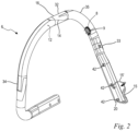
- FIG. 4 The end 20 of the front handle 6 is shown, with the connecting cables 15, 15' protruding from the end 20 of the front handle 6.
- the handle tube insert 17 is located outside the front handle 6.
- the connecting cables 15, 15' are to be inserted into the cable duct 18.
- the handle tube insert 17 is then to be pushed in the insertion direction 48 into the interior 10 of the front handle 6, as shown in Fig. 5 shown.
- the connecting cables 15, 15' are to be guided through the cable channel 18 of the handlebar insert 17.
- the connecting cables 15, 15' can be clamped into the further cable channel 49 via the lugs 50 ( Fig. 6 ).
- the handle tube insert 17 can then be pushed into the front handle 6 until it stops.
Landscapes
- Life Sciences & Earth Sciences (AREA)
- Biodiversity & Conservation Biology (AREA)
- Ecology (AREA)
- Forests & Forestry (AREA)
- Environmental Sciences (AREA)
- Engineering & Computer Science (AREA)
- Mechanical Engineering (AREA)
- Harvester Elements (AREA)
- Dental Tools And Instruments Or Auxiliary Dental Instruments (AREA)
Claims (14)
- Outil de travail à main,- comprenant un boîtier (2), le boîtier (2) présentant un côté supérieur (26), un côté inférieur (27), un premier côté longitudinal (28) et un deuxième côté longitudinal (29), le côté supérieur (26) et le côté inférieur (27) étant reliés entre eux par les deux côtés longitudinaux (28, 29),- comprenant un moteur d'entraînement (3) agencé dans le boîtier (2), le moteur d'entraînement (3) entraînant un outil (5) agencé à l'extrémité avant (30) du boîtier (2),- comprenant une poignée avant (6) et une poignée arrière (36), la poignée avant (6) étant réalisée sous forme de poignée étrier et comprenant une partie transversale (32) s'étendant le long du côté supérieur (26) du boîtier (2) et une partie latérale (33) s'étendant le long de l'un des deux côtés longitudinaux (28, 29) du boîtier (2),- la poignée avant (6) comprenant une paroi (7) et un espace intérieur (10) entouré par la paroi (7), la paroi (7) de la poignée avant (6) comprenant un côté intérieur (11) tourné vers l'espace intérieur (10) et un côté extérieur (12) opposé à l'espace intérieur (10),- un premier élément fonctionnel électrique (13) étant agencé dans le boîtier (2), et- au moins un deuxième élément fonctionnel électrique (14) étant agencé sur la face extérieure (12) de la poignée avant (6),- le premier élément fonctionnel électrique (13) étant relié au deuxième élément fonctionnel (14) par au moins un câble de connexion (15),caractérisé en ce que ledit au moins un câble de connexion (15) est agencé au moins en partie dans l'espace intérieur (10) de la poignée avant (6) dans la zone de la partie latérale (33) de la poignée avant (6).
- Outil de travail selon la revendication 1,
caractérisé en ce que le deuxième élément fonctionnel (14) est conçu sous la forme d'une feuille chauffante. - Outil de travail selon la revendication 1,
caractérisé en ce que le deuxième élément fonctionnel (14) est conçu sous la forme d'un capteur. - Outil de travail selon l'une des revendications 1 à 3,
caractérisé en ce que le premier élément fonctionnel électrique (13) est une source d'énergie pour alimenter le deuxième élément fonctionnel (14) en courant électrique. - Outil de travail selon la revendication 3,
caractérisé en ce que le premier élément fonctionnel électrique (14) est une unité de commande pour le traitement de signaux de données. - Outil de travail selon l'une des revendications 1 à 5,
caractérisé en ce qu'une ouverture (8) est prévue sur la paroi (7) de la poignée avant (6) vers le deuxième élément fonctionnel électrique (14), l'ouverture (8) s'étendant de la face extérieure (12) de la paroi (7) vers le côté intérieur (11) de la paroi (7), ledit un câble de connexion (15) s'étendant depuis le côté extérieur (12) de la paroi (7), à travers l'ouverture (8), dans l'espace intérieur (10) de la poignée (6). - Outil de travail selon la revendication 6,
caractérisé en ce que l'ouverture (8) est pourvue d'un passe-câble (9) servant de protection des bords. - Outil de travail selon l'une des revendications 1 à 7,
caractérisé en ce que la poignée avant (6) comprend une partie de maintien (16) s'étendant approximativement horizontalement, l'ouverture (8) de la paroi (7) étant ménagée à l'extérieur de la partie de maintien (16). - Outil de travail selon l'une des revendications 1 à 8,
caractérisé en ce que la partie transversale (32) et la partie latérale (33) de la poignée avant (6) sont reliées entre elles par une partie de liaison courbée (35), l'ouverture (8) étant prévue dans la partie latérale (33) adjacente à la partie de liaison (35). - Outil de travail selon l'une des revendications 1 à 9,
caractérisé en ce que la poignée (6) est formée d'aluminium ou de matière plastique. - Outil de travail selon l'une des revendications 1 à 10,
caractérisé en ce que l'outil de travail (1) comprend un insert tubulaire (17) de poignée pour fixer la poignée avant (6) au boîtier (2) de l'outil de travail (1), l'insert tubulaire (17) de poignée étant agencé dans l'espace intérieur (10) de la poignée (6) à une extrémité (20) de la poignée avant (6). - Outil de travail selon la revendication 11,
caractérisé en ce que l'insert de poignée (17) comprend un canal de câble (18) pour guider ledit au moins un câble de connexion (15). - Outil de travail selon la revendication 11 ou la revendication 12,
caractérisé en ce que l'insert tubulaire (17) de poignée comprend une fixation de câble (19) pour serrer ledit au moins un câble de connexion (15). - Outil de travail selon la revendication 13,
caractérisé en ce que le câble de connexion (15) s'étend depuis le côté extérieur (12) de la paroi (7) de la poignée avant (6) à travers l'espace intérieur (10) de la poignée avant (6) par le canal de connexion (15) de l'insert tubulaire (17) de poignée, jusqu'à ladite une extrémité (20) de la poignée avant (6).
Priority Applications (3)
| Application Number | Priority Date | Filing Date | Title |
|---|---|---|---|
| EP22154068.5A EP4219084B1 (fr) | 2022-01-28 | 2022-01-28 | Outil de travail portatif |
| CN202310072373.9A CN116508522A (zh) | 2022-01-28 | 2023-01-13 | 手持式工作器具 |
| US18/159,791 US20230241756A1 (en) | 2022-01-28 | 2023-01-26 | Handheld work apparatus |
Applications Claiming Priority (1)
| Application Number | Priority Date | Filing Date | Title |
|---|---|---|---|
| EP22154068.5A EP4219084B1 (fr) | 2022-01-28 | 2022-01-28 | Outil de travail portatif |
Publications (2)
| Publication Number | Publication Date |
|---|---|
| EP4219084A1 EP4219084A1 (fr) | 2023-08-02 |
| EP4219084B1 true EP4219084B1 (fr) | 2025-06-25 |
Family
ID=80122736
Family Applications (1)
| Application Number | Title | Priority Date | Filing Date |
|---|---|---|---|
| EP22154068.5A Active EP4219084B1 (fr) | 2022-01-28 | 2022-01-28 | Outil de travail portatif |
Country Status (3)
| Country | Link |
|---|---|
| US (1) | US20230241756A1 (fr) |
| EP (1) | EP4219084B1 (fr) |
| CN (1) | CN116508522A (fr) |
Families Citing this family (3)
| Publication number | Priority date | Publication date | Assignee | Title |
|---|---|---|---|---|
| JP1720038S (ja) * | 2021-10-18 | 2022-07-19 | 剪定機本体 | |
| USD1084799S1 (en) * | 2021-11-09 | 2025-07-22 | Husqvarna Ab | Hedge trimmer |
| USD1084800S1 (en) * | 2021-11-09 | 2025-07-22 | Husqvarna Ab | Hedge trimmer |
Family Cites Families (5)
| Publication number | Priority date | Publication date | Assignee | Title |
|---|---|---|---|---|
| SE388336B (sv) * | 1974-06-18 | 1976-09-27 | Jonsereds Fabrikers Ab | Rorformigt handtag for eller vid berbar motorkedjesag, i vilket handtag er monterat ett elektriskt vermeelement och sett for dess framstellning |
| DE8617528U1 (de) * | 1986-07-01 | 1986-08-14 | Fa. Andreas Stihl, 7050 Waiblingen | Heizeinrichtung für ein tragbares Arbeitsgerät |
| DE20208761U1 (de) * | 2002-06-06 | 2003-10-09 | Dolmar GmbH, 22045 Hamburg | Beheizbare Griffe, für handgehaltene Arbeitsgeräte |
| DE20308674U1 (de) * | 2003-06-04 | 2003-08-28 | Dolmar GmbH, 22045 Hamburg | Handgeführtes Werkzeug mit Griffheizung auf Mikrowellen-Basis |
| DE102015016485A1 (de) * | 2015-12-15 | 2017-06-22 | Andreas Stihl Ag & Co. Kg | Handgeführtes Arbeitsgerät mit einer Steuereinrichtung |
-
2022
- 2022-01-28 EP EP22154068.5A patent/EP4219084B1/fr active Active
-
2023
- 2023-01-13 CN CN202310072373.9A patent/CN116508522A/zh active Pending
- 2023-01-26 US US18/159,791 patent/US20230241756A1/en active Pending
Also Published As
| Publication number | Publication date |
|---|---|
| EP4219084A1 (fr) | 2023-08-02 |
| CN116508522A (zh) | 2023-08-01 |
| US20230241756A1 (en) | 2023-08-03 |
Similar Documents
| Publication | Publication Date | Title |
|---|---|---|
| EP4219084B1 (fr) | Outil de travail portatif | |
| EP2223781B1 (fr) | Appareil de travail portatif fonctionnant sur batterie | |
| US5323502A (en) | Wire stripping tool | |
| EP3824714B1 (fr) | Appareil d'usinage pourvu de partie tubulaire et de dispositif câble ainsi que procédé de montage | |
| DE3216446A1 (de) | Sicherheitseinrichtung an einem tragbaren, motorisch angetriebenen handgeraet | |
| DE112008001929T5 (de) | Isolierendes Hand-Werkzeug | |
| DE2317060A1 (de) | Verbindungsklammer fuer leitungen | |
| EP4488007A1 (fr) | Outil | |
| WO2019063212A1 (fr) | Bloc-batterie | |
| DE202015001919U1 (de) | Kettensäge | |
| DE102015207149A1 (de) | Elektrisch isolierendes Verbindungsmittel für Handwerkzeugmaschine | |
| DE102015114134B4 (de) | Anschlusseinrichtung zum elektrischen Kontaktieren einer Leitung, insbesondere eines Flachbandkabels | |
| DE102005036885B4 (de) | Handgeführtes Arbeitsgerät | |
| DE102005051886A1 (de) | Handgeführtes Arbeitsgerät | |
| DE1046133B (de) | Zange zum Abisolieren von elektrischen Leitungen | |
| EP4025386A1 (fr) | Insert de sertissage et pince de sertissage | |
| DE4301764A1 (de) | Mehrzweckwerkzeug | |
| DE2932501C2 (de) | Abisoliergerät | |
| EP1507324B1 (fr) | Dispositif de dénudage Uniplus | |
| DE102017217487A1 (de) | Akkupack | |
| DE102023110264A1 (de) | Handgehaltenes gartengerät | |
| DE102007013643B4 (de) | Zugentlastung eines Kabels für ein elektromotorisch betriebenes, handgeführtes Arbeitsgerät | |
| DE102015216252B4 (de) | Handgehaltenes Gartengerät | |
| DE102023117457A1 (de) | Griffanordnung und Arbeitsgerät mit einer Griffanordnung | |
| DE102023117456A1 (de) | Arbeitsgerät |
Legal Events
| Date | Code | Title | Description |
|---|---|---|---|
| PUAI | Public reference made under article 153(3) epc to a published international application that has entered the european phase |
Free format text: ORIGINAL CODE: 0009012 |
|
| STAA | Information on the status of an ep patent application or granted ep patent |
Free format text: STATUS: THE APPLICATION HAS BEEN PUBLISHED |
|
| AK | Designated contracting states |
Kind code of ref document: A1 Designated state(s): AL AT BE BG CH CY CZ DE DK EE ES FI FR GB GR HR HU IE IS IT LI LT LU LV MC MK MT NL NO PL PT RO RS SE SI SK SM TR |
|
| STAA | Information on the status of an ep patent application or granted ep patent |
Free format text: STATUS: REQUEST FOR EXAMINATION WAS MADE |
|
| 17P | Request for examination filed |
Effective date: 20240125 |
|
| RBV | Designated contracting states (corrected) |
Designated state(s): AL AT BE BG CH CY CZ DE DK EE ES FI FR GB GR HR HU IE IS IT LI LT LU LV MC MK MT NL NO PL PT RO RS SE SI SK SM TR |
|
| RIN1 | Information on inventor provided before grant (corrected) |
Inventor name: AUPPERLE, JUERGEN Inventor name: NEFZGER, MARKUS |
|
| GRAP | Despatch of communication of intention to grant a patent |
Free format text: ORIGINAL CODE: EPIDOSNIGR1 |
|
| STAA | Information on the status of an ep patent application or granted ep patent |
Free format text: STATUS: GRANT OF PATENT IS INTENDED |
|
| INTG | Intention to grant announced |
Effective date: 20250122 |
|
| GRAS | Grant fee paid |
Free format text: ORIGINAL CODE: EPIDOSNIGR3 |
|
| GRAA | (expected) grant |
Free format text: ORIGINAL CODE: 0009210 |
|
| STAA | Information on the status of an ep patent application or granted ep patent |
Free format text: STATUS: THE PATENT HAS BEEN GRANTED |
|
| AK | Designated contracting states |
Kind code of ref document: B1 Designated state(s): AL AT BE BG CH CY CZ DE DK EE ES FI FR GB GR HR HU IE IS IT LI LT LU LV MC MK MT NL NO PL PT RO RS SE SI SK SM TR |
|
| REG | Reference to a national code |
Ref country code: GB Ref legal event code: FG4D Free format text: NOT ENGLISH |
|
| REG | Reference to a national code |
Ref country code: CH Ref legal event code: EP |
|
| REG | Reference to a national code |
Ref country code: CH Ref legal event code: EP |
|
| REG | Reference to a national code |
Ref country code: IE Ref legal event code: FG4D Free format text: LANGUAGE OF EP DOCUMENT: GERMAN |
|
| REG | Reference to a national code |
Ref country code: DE Ref legal event code: R096 Ref document number: 502022004374 Country of ref document: DE |
|
| REG | Reference to a national code |
Ref country code: SE Ref legal event code: TRGR |
|
| PG25 | Lapsed in a contracting state [announced via postgrant information from national office to epo] |
Ref country code: FI Free format text: LAPSE BECAUSE OF FAILURE TO SUBMIT A TRANSLATION OF THE DESCRIPTION OR TO PAY THE FEE WITHIN THE PRESCRIBED TIME-LIMIT Effective date: 20250625 |
|
| REG | Reference to a national code |
Ref country code: LT Ref legal event code: MG9D |
|
| PG25 | Lapsed in a contracting state [announced via postgrant information from national office to epo] |
Ref country code: NO Free format text: LAPSE BECAUSE OF FAILURE TO SUBMIT A TRANSLATION OF THE DESCRIPTION OR TO PAY THE FEE WITHIN THE PRESCRIBED TIME-LIMIT Effective date: 20250925 Ref country code: GR Free format text: LAPSE BECAUSE OF FAILURE TO SUBMIT A TRANSLATION OF THE DESCRIPTION OR TO PAY THE FEE WITHIN THE PRESCRIBED TIME-LIMIT Effective date: 20250926 |
|
| PG25 | Lapsed in a contracting state [announced via postgrant information from national office to epo] |
Ref country code: BG Free format text: LAPSE BECAUSE OF FAILURE TO SUBMIT A TRANSLATION OF THE DESCRIPTION OR TO PAY THE FEE WITHIN THE PRESCRIBED TIME-LIMIT Effective date: 20250625 |
|
| PG25 | Lapsed in a contracting state [announced via postgrant information from national office to epo] |
Ref country code: HR Free format text: LAPSE BECAUSE OF FAILURE TO SUBMIT A TRANSLATION OF THE DESCRIPTION OR TO PAY THE FEE WITHIN THE PRESCRIBED TIME-LIMIT Effective date: 20250625 |
|
| PG25 | Lapsed in a contracting state [announced via postgrant information from national office to epo] |
Ref country code: RS Free format text: LAPSE BECAUSE OF FAILURE TO SUBMIT A TRANSLATION OF THE DESCRIPTION OR TO PAY THE FEE WITHIN THE PRESCRIBED TIME-LIMIT Effective date: 20250925 |
|
| PG25 | Lapsed in a contracting state [announced via postgrant information from national office to epo] |
Ref country code: LV Free format text: LAPSE BECAUSE OF FAILURE TO SUBMIT A TRANSLATION OF THE DESCRIPTION OR TO PAY THE FEE WITHIN THE PRESCRIBED TIME-LIMIT Effective date: 20250625 |
|
| REG | Reference to a national code |
Ref country code: NL Ref legal event code: MP Effective date: 20250625 |
|
| PG25 | Lapsed in a contracting state [announced via postgrant information from national office to epo] |
Ref country code: NL Free format text: LAPSE BECAUSE OF FAILURE TO SUBMIT A TRANSLATION OF THE DESCRIPTION OR TO PAY THE FEE WITHIN THE PRESCRIBED TIME-LIMIT Effective date: 20250625 |
|
| PG25 | Lapsed in a contracting state [announced via postgrant information from national office to epo] |
Ref country code: PT Free format text: LAPSE BECAUSE OF FAILURE TO SUBMIT A TRANSLATION OF THE DESCRIPTION OR TO PAY THE FEE WITHIN THE PRESCRIBED TIME-LIMIT Effective date: 20251027 |
|
| PG25 | Lapsed in a contracting state [announced via postgrant information from national office to epo] |
Ref country code: IS Free format text: LAPSE BECAUSE OF FAILURE TO SUBMIT A TRANSLATION OF THE DESCRIPTION OR TO PAY THE FEE WITHIN THE PRESCRIBED TIME-LIMIT Effective date: 20251025 |
|
| PG25 | Lapsed in a contracting state [announced via postgrant information from national office to epo] |
Ref country code: SM Free format text: LAPSE BECAUSE OF FAILURE TO SUBMIT A TRANSLATION OF THE DESCRIPTION OR TO PAY THE FEE WITHIN THE PRESCRIBED TIME-LIMIT Effective date: 20250625 |
|
| PG25 | Lapsed in a contracting state [announced via postgrant information from national office to epo] |
Ref country code: CZ Free format text: LAPSE BECAUSE OF FAILURE TO SUBMIT A TRANSLATION OF THE DESCRIPTION OR TO PAY THE FEE WITHIN THE PRESCRIBED TIME-LIMIT Effective date: 20250625 |
|
| PG25 | Lapsed in a contracting state [announced via postgrant information from national office to epo] |
Ref country code: PL Free format text: LAPSE BECAUSE OF FAILURE TO SUBMIT A TRANSLATION OF THE DESCRIPTION OR TO PAY THE FEE WITHIN THE PRESCRIBED TIME-LIMIT Effective date: 20250625 |
|
| PG25 | Lapsed in a contracting state [announced via postgrant information from national office to epo] |
Ref country code: EE Free format text: LAPSE BECAUSE OF FAILURE TO SUBMIT A TRANSLATION OF THE DESCRIPTION OR TO PAY THE FEE WITHIN THE PRESCRIBED TIME-LIMIT Effective date: 20250625 |
|
| PG25 | Lapsed in a contracting state [announced via postgrant information from national office to epo] |
Ref country code: SK Free format text: LAPSE BECAUSE OF FAILURE TO SUBMIT A TRANSLATION OF THE DESCRIPTION OR TO PAY THE FEE WITHIN THE PRESCRIBED TIME-LIMIT Effective date: 20250625 |
|
| PG25 | Lapsed in a contracting state [announced via postgrant information from national office to epo] |
Ref country code: ES Free format text: LAPSE BECAUSE OF FAILURE TO SUBMIT A TRANSLATION OF THE DESCRIPTION OR TO PAY THE FEE WITHIN THE PRESCRIBED TIME-LIMIT Effective date: 20250625 |
|
| PGFP | Annual fee paid to national office [announced via postgrant information from national office to epo] |
Ref country code: SE Payment date: 20260126 Year of fee payment: 5 |
|
| PGFP | Annual fee paid to national office [announced via postgrant information from national office to epo] |
Ref country code: GB Payment date: 20260126 Year of fee payment: 5 |
|
| PG25 | Lapsed in a contracting state [announced via postgrant information from national office to epo] |
Ref country code: DK Free format text: LAPSE BECAUSE OF FAILURE TO SUBMIT A TRANSLATION OF THE DESCRIPTION OR TO PAY THE FEE WITHIN THE PRESCRIBED TIME-LIMIT Effective date: 20250625 |
|
| PGFP | Annual fee paid to national office [announced via postgrant information from national office to epo] |
Ref country code: DE Payment date: 20260127 Year of fee payment: 5 |
|
| PGFP | Annual fee paid to national office [announced via postgrant information from national office to epo] |
Ref country code: AT Payment date: 20260301 Year of fee payment: 5 |
|
| PG25 | Lapsed in a contracting state [announced via postgrant information from national office to epo] |
Ref country code: IT Free format text: LAPSE BECAUSE OF FAILURE TO SUBMIT A TRANSLATION OF THE DESCRIPTION OR TO PAY THE FEE WITHIN THE PRESCRIBED TIME-LIMIT Effective date: 20250625 |
|
| PGFP | Annual fee paid to national office [announced via postgrant information from national office to epo] |
Ref country code: FR Payment date: 20260126 Year of fee payment: 5 |