EP4186571B1 - Procédé de fabrication et moule pour volant artificiel - Google Patents
Procédé de fabrication et moule pour volant artificiel Download PDFInfo
- Publication number
- EP4186571B1 EP4186571B1 EP22206361.2A EP22206361A EP4186571B1 EP 4186571 B1 EP4186571 B1 EP 4186571B1 EP 22206361 A EP22206361 A EP 22206361A EP 4186571 B1 EP4186571 B1 EP 4186571B1
- Authority
- EP
- European Patent Office
- Prior art keywords
- annular grooves
- shuttlecock
- grooves
- semi
- mold
- Prior art date
- Legal status (The legal status is an assumption and is not a legal conclusion. Google has not performed a legal analysis and makes no representation as to the accuracy of the status listed.)
- Active
Links
Images




Classifications
-
- B—PERFORMING OPERATIONS; TRANSPORTING
- B29—WORKING OF PLASTICS; WORKING OF SUBSTANCES IN A PLASTIC STATE IN GENERAL
- B29C—SHAPING OR JOINING OF PLASTICS; SHAPING OF MATERIAL IN A PLASTIC STATE, NOT OTHERWISE PROVIDED FOR; AFTER-TREATMENT OF THE SHAPED PRODUCTS, e.g. REPAIRING
- B29C45/00—Injection moulding, i.e. forcing the required volume of moulding material through a nozzle into a closed mould; Apparatus therefor
- B29C45/14—Injection moulding, i.e. forcing the required volume of moulding material through a nozzle into a closed mould; Apparatus therefor incorporating preformed parts or layers, e.g. injection moulding around inserts or for coating articles
- B29C45/14065—Positioning or centering articles in the mould
-
- A—HUMAN NECESSITIES
- A63—SPORTS; GAMES; AMUSEMENTS
- A63B—APPARATUS FOR PHYSICAL TRAINING, GYMNASTICS, SWIMMING, CLIMBING, OR FENCING; BALL GAMES; TRAINING EQUIPMENT
- A63B67/00—Sporting games or accessories therefor, not provided for in groups A63B1/00 - A63B65/00
- A63B67/18—Badminton or similar games with feathered missiles
- A63B67/183—Feathered missiles
- A63B67/187—Shuttlecocks
- A63B67/19—Shuttlecocks with several feathers connected to each other
-
- B—PERFORMING OPERATIONS; TRANSPORTING
- B29—WORKING OF PLASTICS; WORKING OF SUBSTANCES IN A PLASTIC STATE IN GENERAL
- B29C—SHAPING OR JOINING OF PLASTICS; SHAPING OF MATERIAL IN A PLASTIC STATE, NOT OTHERWISE PROVIDED FOR; AFTER-TREATMENT OF THE SHAPED PRODUCTS, e.g. REPAIRING
- B29C45/00—Injection moulding, i.e. forcing the required volume of moulding material through a nozzle into a closed mould; Apparatus therefor
- B29C45/14—Injection moulding, i.e. forcing the required volume of moulding material through a nozzle into a closed mould; Apparatus therefor incorporating preformed parts or layers, e.g. injection moulding around inserts or for coating articles
- B29C45/14467—Joining articles or parts of a single article
-
- B—PERFORMING OPERATIONS; TRANSPORTING
- B29—WORKING OF PLASTICS; WORKING OF SUBSTANCES IN A PLASTIC STATE IN GENERAL
- B29C—SHAPING OR JOINING OF PLASTICS; SHAPING OF MATERIAL IN A PLASTIC STATE, NOT OTHERWISE PROVIDED FOR; AFTER-TREATMENT OF THE SHAPED PRODUCTS, e.g. REPAIRING
- B29C45/00—Injection moulding, i.e. forcing the required volume of moulding material through a nozzle into a closed mould; Apparatus therefor
- B29C45/0053—Injection moulding, i.e. forcing the required volume of moulding material through a nozzle into a closed mould; Apparatus therefor combined with a final operation, e.g. shaping
- B29C45/006—Joining parts moulded in separate cavities
- B29C45/0062—Joined by injection moulding
-
- B—PERFORMING OPERATIONS; TRANSPORTING
- B29—WORKING OF PLASTICS; WORKING OF SUBSTANCES IN A PLASTIC STATE IN GENERAL
- B29C—SHAPING OR JOINING OF PLASTICS; SHAPING OF MATERIAL IN A PLASTIC STATE, NOT OTHERWISE PROVIDED FOR; AFTER-TREATMENT OF THE SHAPED PRODUCTS, e.g. REPAIRING
- B29C45/00—Injection moulding, i.e. forcing the required volume of moulding material through a nozzle into a closed mould; Apparatus therefor
- B29C45/14—Injection moulding, i.e. forcing the required volume of moulding material through a nozzle into a closed mould; Apparatus therefor incorporating preformed parts or layers, e.g. injection moulding around inserts or for coating articles
- B29C45/14008—Inserting articles into the mould
-
- B—PERFORMING OPERATIONS; TRANSPORTING
- B29—WORKING OF PLASTICS; WORKING OF SUBSTANCES IN A PLASTIC STATE IN GENERAL
- B29C—SHAPING OR JOINING OF PLASTICS; SHAPING OF MATERIAL IN A PLASTIC STATE, NOT OTHERWISE PROVIDED FOR; AFTER-TREATMENT OF THE SHAPED PRODUCTS, e.g. REPAIRING
- B29C45/00—Injection moulding, i.e. forcing the required volume of moulding material through a nozzle into a closed mould; Apparatus therefor
- B29C45/14—Injection moulding, i.e. forcing the required volume of moulding material through a nozzle into a closed mould; Apparatus therefor incorporating preformed parts or layers, e.g. injection moulding around inserts or for coating articles
- B29C45/14467—Joining articles or parts of a single article
- B29C45/14475—Joining juxtaposed parts of a single article, e.g. edges of a folded container blank
-
- B—PERFORMING OPERATIONS; TRANSPORTING
- B29—WORKING OF PLASTICS; WORKING OF SUBSTANCES IN A PLASTIC STATE IN GENERAL
- B29C—SHAPING OR JOINING OF PLASTICS; SHAPING OF MATERIAL IN A PLASTIC STATE, NOT OTHERWISE PROVIDED FOR; AFTER-TREATMENT OF THE SHAPED PRODUCTS, e.g. REPAIRING
- B29C45/00—Injection moulding, i.e. forcing the required volume of moulding material through a nozzle into a closed mould; Apparatus therefor
- B29C45/17—Component parts, details or accessories; Auxiliary operations
- B29C45/26—Moulds
- B29C45/263—Moulds with mould wall parts provided with fine grooves or impressions, e.g. for record discs
-
- A—HUMAN NECESSITIES
- A63—SPORTS; GAMES; AMUSEMENTS
- A63B—APPARATUS FOR PHYSICAL TRAINING, GYMNASTICS, SWIMMING, CLIMBING, OR FENCING; BALL GAMES; TRAINING EQUIPMENT
- A63B2102/00—Application of clubs, bats, rackets or the like to the sporting activity ; particular sports involving the use of balls and clubs, bats, rackets, or the like
- A63B2102/04—Badminton
-
- B—PERFORMING OPERATIONS; TRANSPORTING
- B29—WORKING OF PLASTICS; WORKING OF SUBSTANCES IN A PLASTIC STATE IN GENERAL
- B29C—SHAPING OR JOINING OF PLASTICS; SHAPING OF MATERIAL IN A PLASTIC STATE, NOT OTHERWISE PROVIDED FOR; AFTER-TREATMENT OF THE SHAPED PRODUCTS, e.g. REPAIRING
- B29C45/00—Injection moulding, i.e. forcing the required volume of moulding material through a nozzle into a closed mould; Apparatus therefor
- B29C45/14—Injection moulding, i.e. forcing the required volume of moulding material through a nozzle into a closed mould; Apparatus therefor incorporating preformed parts or layers, e.g. injection moulding around inserts or for coating articles
- B29C45/14336—Coating a portion of the article, e.g. the edge of the article
- B29C45/14385—Coating a portion of a bundle of inserts, e.g. making brushes
-
- B—PERFORMING OPERATIONS; TRANSPORTING
- B29—WORKING OF PLASTICS; WORKING OF SUBSTANCES IN A PLASTIC STATE IN GENERAL
- B29L—INDEXING SCHEME ASSOCIATED WITH SUBCLASS B29C, RELATING TO PARTICULAR ARTICLES
- B29L2031/00—Other particular articles
- B29L2031/52—Sports equipment ; Games; Articles for amusement; Toys
Definitions
- the present disclosure relates to a manufacturing method and a mold for an artificial shuttlecock.
- Badminton games are common and popular ball games, and badminton players play the games by hitting a shuttlecock.
- a conventional shuttlecock is primarily in a structure of natural feather combined at a ball head.
- the natural feather is mostly goose feather or duck feather, and is bleached, selected and then made into shuttlecocks.
- the acquisition of natural feather has become increasingly difficult, and the selection process is complicated and labor consuming.
- artificial shuttlecocks having feathers made of a light foam material have more complicated manufacturing steps. For example, a plurality of feathers are respectively adhered to one end of a plurality of stems, and the other end of each of the stems is inserted at a ball head, so as to form a semi-finished shuttlecock having the ball head, the stems and the feathers. Next, linen yarn is wound around these stems to keep the distances between the stems constant. After winding of the linen yarn, the linen yarn needs to be tied and knotted manually, and glue is applied to the linen yarn. A connecting member of an artificial shuttlecock is formed once the glue is dried. In other words, there is need for an improvement for the complicated manufacturing steps of a connecting member of an artificial shuttlecock having feathers made of a foam material.
- GB 686059 A relates to mold for manufacturing an artificial shuttlecock including a male mold and a female mold.
- the male mold includes a cone frustum and a plurality of first annular grooves.
- the first annular grooves are disposed apart on an outside of the cone frustum.
- the female mold includes a tapered slot, a plurality of second annular grooves and an injection channel.
- the second annular grooves are disposed apart on an inner surface of the tapered slot.
- Each of the first annular grooves corresponds to each of the second annular grooves to form a plurality of molded grooves.
- the injection channel communicates with the second annular grooves, and the molded grooves communicate with the injection channel through the second annular grooves.
- a plastic material is injected from the injection channel, and the plastic material is solidified in the molded grooves to form a plurality of connecting members.
- KR 2015 0039912 A relates to a manufacturing method for an artificial shuttlecock, comprising providing a semi-finished shuttlecock, the semi-finished shuttlecock comprising a plurality of stems and a plurality of feathers, one end of each of the stems to be inserted at the ball head, the feathers connected to one other end of each of the stems; placing the semi-finished shuttlecock in a male mold, the male mold comprising a cone frustum the semi-finished shuttlecock disposed on the outside of the cone frustum; placing the semi-finished shuttlecock and the male mold into a female mold.
- a manufacturing method for an artificial shuttlecock according to claim 1 and a mold for manufacturing an artificial shuttlecock from a semi-finished shuttlecock according to claim 8 are provided.
- the manufacturing method includes: providing a semi-finished shuttlecock including a ball head, a plurality of stems and a plurality of feathers, one end of each of the stems inserted at the ball head, the feathers connected to the other end of each of the stems; placing the semi-finished shuttlecock into a male mold, the male mold including a cone frustum and a plurality of first annular grooves, the first annular grooves disposed apart on an outside of the cone frustum, the semi-finished shuttlecock placed on the outside of the cone frustum; placing the semi-finished shuttlecock and the male mold into a female mode, the female mold including a tapered slot, a plurality of second annular grooves and an injection channel, the second annular grooves disposed apart on an inner surface of the tapered slot, the injection channel communicating with the second annular grooves, each of the first annular grooves corresponding to each of the second annular grooves to form a
- the present disclosure further provides a mold for manufacturing an artificial shuttlecock from a semi-finished shuttlecock.
- the semi-finished shuttlecock includes a ball head, a plurality of stems and a plurality of feathers. One end of each of the stems is inserted at the ball head, and the feathers are connected to the other end of each of the stems.
- the mold includes a male mold and a female mold.
- the male mold includes a cone frustum and a plurality of first annular grooves.
- the cone frustum has an outside, and the semi-finished shuttlecock is placed on the outside of the cone frustum.
- the first annular grooves are disposed apart on the outside of the cone frustum.
- the female mold includes a tapered slot, a plurality of second annular grooves and an injection channel.
- the tapered slot has an inner surface.
- the second annular grooves are disposed apart on the inner surface of the tapered slot.
- each of the first annular grooves corresponds to each of the second annular grooves to form a plurality of molded grooves.
- the injection channel communicates with the second annular grooves, and the molded grooves communicate with the injection channel through the second annular grooves.
- a plastic material is injected from the injection channel, and the plastic material is solidified in the molded grooves to form a plurality of connecting members.
- the first annular grooves are parallel to a top surface of the cone frustum.
- the male mold includes a plurality of first stem grooves.
- the first stem grooves are disposed apart on the outside of the cone frustum, and intersect the first annular grooves.
- the stems of the semi-finished shuttlecock are accommodated in the first stem grooves.
- the numbers of the first annular grooves and the second annular grooves are three, respectively, so as to form three molded grooves.
- distances between every two adjacent of the first annular grooves are substantially equal.
- the tapered slot includes a ball head portion and a first cone portion, wherein the first cone portion is disposed adjacent to the ball head portion.
- the ball head of the semi-finished shuttlecock is accommodated in the ball head portion, and the second annular grooves are disposed at the first cone portion.
- the tapered slot includes a second cone portion, which is disposed adjacent to the first cone portion.
- An inner diameter of the second cone portion is greater than an inner diameter of the first cone portion.
- the feathers of the semi-finished shuttlecock are accommodated in the second cone portion.
- the mold in the manufacturing method and the mold for an artificial shuttlecock according to the present disclosure, includes a male mold and a female mold.
- the male mold includes a cone frustum and a plurality of first annular grooves, and the first annular grooves are disposed apart on an outside of the cone frustum.
- the female mold includes a tapered slot and a plurality of second annular grooves, and the second annular grooves are disposed apart at the tapered slot.
- the first annular grooves correspond to the second annular grooves to form molded grooves.
- the female mold further includes an injection channel communicating with the second annular grooves.
- the plastic material is solidified in the molded grooves to form a plurality of connecting members, thereby forming the artificial shuttlecock.
- steps including winding, tying, knotting and gluing of wheel lines for connecting members using a linen yarn can be eliminated, further enhancing manufacturing efficiency of artificial shuttlecocks.
- FIG. 1 shows a flowchart of a manufacturing method for an artificial shuttlecock according to an embodiment of the present disclosure.
- FIG. 2 shows a schematic diagram of a semi-finished shuttlecock provided by step S10 in FIG. 1 .
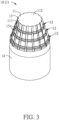
- FIG. 3 shows a schematic diagram of a male mold according to an embodiment of the present disclosure.
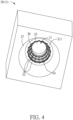
- FIG. 4 shows a schematic diagram of a female mold according to an embodiment of the present disclosure. Refer to FIG. 1 , FIG. 2 , FIG. 3 and FIG. 4 .
- An artificial shuttlecock 9 of this embodiment is manufactured by using a mold 1, with a manufacturing method thereof as shown in FIG. 1 .
- the mold 1 of this embodiment is further described according to details of the steps below.
- step S 10 a semi-finished shuttlecock 9' is provided.
- the manufacturing method for an artificial shuttlecock of this embodiment is primarily a method for manufacturing the artificial shuttlecock 9 (referring to FIG. 1 ) from the semi-finished shuttlecock 9' (as shown in FIG. 1 ).
- the semi-finished shuttlecock 9' includes a ball head 91, a plurality of stems 92 and a plurality of feathers 93.
- One side of the ball head 91 is a semispherical concave surface, and the other side is a flat surface that can be inserted by the stems 92.
- the plurality of stems 92 are disposed apart at the ball head 91, and one end of each of the stems 92 is inserted at the flat surface of the ball head 91.
- each of the stems 92 is connected to the feathers 93, that is, the feathers 93 are respectively connected to the stems 92.
- the stems 92 are made a carbon fiber reinforced resin material, so as to reinforce the durability of the stems 92. More specifically, the stems 92 of this embodiment are formed by stacking unidirectional (UD) carbon fiber fabric and woven glass fiber, hence reinforcing the strength and durability of the stems 92.
- UD unidirectional
- the feathers 93 are connected to the stems 92 by an adhesive and are close to the stems 92.
- every two feathers 93 are combined with one stem 92, that is, every two feathers 93 are connected to two opposite sides of the stem 92, respectively.
- the feathers 93 can be adhered to the stems 92, and then the stems 92 are then inserted to the ball head 91.
- the feathers 93 of this embodiment may also be artificial feathers in substitution for natural feathers.
- the feathers 93 are made of a plastic material having a density between 0.9 g/cm 3 to 1.48 g/cm 3 , and the types of the plastic material may be, for example but not limited to, low-density polyethylene (LDPE), linear low-density polyethylene (LLDPE), polyethylene terephthalate (PET), polyethylene (PE), polypropylene (PP), acrylonitrile-butadiene-styrene (ABS), polyamide (PA) and extruded polyethylene (EPE) plastic materials.
- LDPE low-density polyethylene
- LLDPE linear low-density polyethylene
- PET polyethylene terephthalate
- PE polyethylene
- PE polypropylene
- PP acrylonitrile-butadiene-styrene
- PA extruded polyethylene
- EPE extruded polyethylene
- the overall structure of the feather 93 corresponds to the structure of the natural feather of a shuttlecock.
- the feather 93 may be in a mutually symmetrical structure
- the stem 92 is a mutually symmetrical structure about an axis of symmetry, for example, a kite-shaped structure.
- step S20 the semi-finished shuttlecock 9' is placed into a male mold 10.
- the mold 1 of this embodiment includes a male mold 10 (as shown in FIG. 3 ) and a female mold 20 (as shown in FIG. 4 ).
- the male mold 10 includes a cone frustum 11 and a plurality of first annular grooves 12.
- the cone frustum 11 has an outside 111, and the semi-finished shuttlecock 9' may be placed on the outside 111 of the cone frustum 11.
- the first annular grooves 12 are disposed apart on the outside 111 of the cone frustum 11. More specifically, the first annular grooves 12 surround the outside 111 of the cone frustum 11 in a manner of being parallel to one another along the center axis of the cone frustum 11, such that the first annular grooves 12 are also parallel to a top surface 112 of the cone frustum 11.
- the first annular grooves 12 are used to form a partial structure of connecting members 94 (referring to FIG. 8 ) of the artificial shuttlecock 9.
- the number of the first annular grooves 12 may be determined with reference to the number of connecting members 94 to be formed.
- the number of the first annular grooves 12 of this embodiment may be three, so as to form three connecting members 93 in the subsequent steps.
- distances between every two adjacent of the first annular grooves 12 are equal, and are preferably between 5 mm and 17.5 mm, which includes 5 mm and 17.5 mm.
- the male mold 10 further includes a plurality of first stem grooves 13.
- the first stem grooves 13 are similarly disposed apart on the outside 111 of the cone frustum 11, and intersect the first annular grooves 12.
- the first annular grooves 12 are horizontally disposed on the outside 111 of the cone frustum 11, and the first stem grooves 13 are vertically disposed on the outside 111 of the cone frustum 11, such that the first stem grooves 13 intersect the first annular grooves 12. Because the first annular grooves 12 surround the outside 111 of the cone frustum 11, each of the first annular grooves 12 connects to all of the first stem grooves 13.
- step S20 the semi-finished shuttlecock 9' is placed on the outside 111 of the cone frustum 11, and at the same time the stems 92 of the semi-finished shuttlecock 9' are respectively accommodated in the first stem grooves 13.
- the first stem grooves 13 serve as limiting structures of the stems 92.
- step S30 the semi-finished shuttlecock 9' and the male mold 10 are placed into the female mold 20.
- FIG. 5 shows a schematic diagram of a semi-finished shuttlecock and a male mold placed into a female mold in step S30 in FIG. 1 .
- FIG. 6 shows a section diagram of a mold according to an embodiment of the present disclosure.
- FIG. 7 shows an enlarged schematic diagram of a circled portion of the mold in FIG. 6.
- FIG. 6 is also a section diagram after the male mold in FIG. 3 is combined with the female mold in FIG. 4 .
- the female mold 20 includes a tapered slot 21, a plurality of second annular grooves 22 and an injection channel 23.
- the tapered slot 21 has an inner surface 211 (as shown in FIG.
- the second annular grooves 22 are disposed apart on the inner surface 211 of the tapered slot 21.
- the arrangement positions of the second annular grooves 22 need to mutually correspond to the first annular grooves 12, so the second annular grooves 22 surround the inner surface 211 of the tapered slot 21 in a manner of being parallel to one another along the center axis of the tapered slot 21.
- distances between every two adjacent of the second annular grooves 22 are equal to the distances between every two adjacent of the first annular grooves 21.
- each of the first annular grooves 12 can also correspond to each of the second annular grooves 22 when the male mold 10 is placed into the tapered slot 21 of the female mold 20, so as to together form a plurality of molded grooves M, as shown in FIG. 6 and FIG. 7 .
- the number of the molded grooves M is equal to the number of the first annular grooves 12 (or the second annular grooves 22).
- the numbers of the first annular grooves 12 and the second annular grooves 22 are respectively three, so three molded grooves M can be formed.
- the molded grooves M are grooves for subsequently molding the connecting members 94.
- the injection channel 23 is for injecting a plastic material of the connecting members 94 to be formed.
- the injection channel 22 communicates with the second annular grooves 23.
- the injection channel 23 has three branch channels 231, which respectively communicate with the second annular grooves 22.
- the number of the branch channels 231 is the same as the number of the second annular grooves 22 (also the same as the numbers of the first annular grooves 12 and the molded grooves M).
- step S40 a plastic material is injected from the injection channel 23, and the plastic material is solidified in the molded grooves M to form the plurality of connecting members 94.
- the injection channel 23 communicates with the second annular grooves 22, and the first annular grooves 12 and the second annular grooves 22 together form the molded grooves M; that is, the molded grooves M can communicate with the injection channel 23 through the second annular grooves 22.
- the plastic material can be injected into the injection channel 23, flow into the molded grooves M through the branch channels 231, and then solidify in the molded grooves M to form the connecting members 94.
- the plastic material may be, for example but not limited to, a plastic material such as Polypropylene (PP) or Polyamide (PA), so as to form the connecting members 94 made of PP or PA.
- the first annular grooves 12 are disposed to intersect the first stem grooves 13 (for accommodating the stems 92), the first annular grooves 12 communicate with the first stem grooves 92 at the intersections.
- the plastic material can further flow to the intersections once being injected into the molded grooves M, and solidify on outsides of parts (intersections) of the stems 92, further connecting the solidified and formed connecting members 94 with the stems 92.
- the female mold 20 may also include a plurality of second stem grooves 24, which are disposed apart on the inner surface 211 of the tapered slot 21 and intersect the second annular grooves 22, as shown in FIG. 4 .
- the stems 92 of the semi-finished product 9' may be accommodated in spaces formed by the first stem grooves 13 and the second stem grooves 24, allowing the solidified and formed connecting members 94 to evenly envelop the outsides of the stems 92.
- the tapered slot 21 further includes a ball head portion 25, a first cone portion 26 and the second cone portion 27.
- the first cone portion 26 is disposed adjacent to the ball head portion 25, and the second cone portion 27 is disposed adjacent to the first cone portion 26. That is, the first cone portion 26 is located between the ball head portion 25 and the second cone portion 27.
- the ball head 91 of the semi-finished shuttlecock 9' is accommodated in the ball head portion 25, and the second annular grooves 22 and the second stem grooves 24 are both disposed at the first cone portion 26.
- an inner diameter of the second cone portion 27 is greater than an inner diameter of the first cone portion 26. That is, the second cone portion 27 expands toward an outside of the tapered slot 21, such that the feathers 93 of the semi-finished shuttlecock 9' can be accommodated in the second cone portion 27.
- the male mold 10 further includes a cylindrical portion 14, which is disposed adjacent to the cone frustum 11 and may correspond to the second cone portion 27 of the female mold 20. The feathers 93 may be accommodated between the cylindrical portion 14 and the second cone portion 27.
- step S50 the artificial shuttlecock 9 is removed from the mold 1.
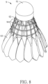
- FIG. 8 shows a schematic diagram of an artificial shuttlecock made using the mold in FIG. 3 .
- the artificial shuttlecock 9 is manufactured after the connecting members 94 are formed from the solidified plastic material in the molded grooves M (step S40). Lastly, the artificial shuttlecock 9 is removed from the mold 1, as shown in FIG. 8 .
- connecting members 94 By forming the connecting members 94 by means of solidifying and molding a plastic material, steps including winding, tying, knotting and gluing of wheel lines for connecting members using a linen yarn can be eliminated, further enhancing manufacturing efficiency of the artificial shuttlecock 9.
- the last step of the manufacturing method for the artificial shuttlecock 9 is applying an adhesive to the entire of the artificial shuttlecock 9, and thus time is needed to wait for the adhesive to dry.
- an adhesive may be applied to the entire artificial shuttlecock 9 by using a light curing adhesive (for example, UV adhesive), similarly enhancing the manufacturing efficiency of the artificial shuttlecock 9.
- the mold in the manufacturing method and the mold for an artificial shuttlecock according to the present disclosure, includes a male mold and a female mold.
- the male mold includes a cone frustum and a plurality of first annular grooves, and the first annular grooves are disposed apart on an outside of the cone frustum.
- the male mold includes a tapered slot and a plurality of second annular grooves, and the second annular grooves are disposed apart at the tapered slot.
- the first annular grooves correspond to the second annular grooves to form molded grooves.
- the female mold further includes an injection channel communicating with the second annular grooves.
- the plastic material is solidified in the molded grooves to form a plurality of connecting members, thereby forming the artificial shuttlecock.
- steps including winding, tying, knotting and gluing of wheel lines for connecting members using a linen yarn can be eliminated, further enhancing manufacturing efficiency of artificial shuttlecocks.
Landscapes
- Engineering & Computer Science (AREA)
- Manufacturing & Machinery (AREA)
- Mechanical Engineering (AREA)
- Health & Medical Sciences (AREA)
- General Health & Medical Sciences (AREA)
- Physical Education & Sports Medicine (AREA)
- Injection Moulding Of Plastics Or The Like (AREA)
- Moulds For Moulding Plastics Or The Like (AREA)
- Moulding By Coating Moulds (AREA)
Claims (12)
- Procédé de fabrication d'un volant artificiel (9), comprenant :la fourniture d'un volant semi-fini (9'), le volant semi-fini (9') comprenant une tête de balle (91), une pluralité de tiges (92) et une pluralité de plumes (93), une extrémité de chacune des tiges (92) insérée au niveau de la tête de balle (91), les plumes (93) reliées à une autre extrémité de chacune des tiges (92) ;le placement du volant semi-fini (9') dans un moule mâle (10), le moule mâle (10) comprenant un tronc de cône (11) et une pluralité de premières rainures annulaires (12), les premières rainures annulaires (12) étant disposées à l'écart sur un extérieur du tronc de cône (11), le volant semi-fini (9') étant disposé sur l'extérieur du tronc de cône (11) ;le placement du volant semi-fini (9') et du moule mâle (10) dans un moule femelle (20), le moule femelle (20) comprenant une fente conique (21), une pluralité de deuxièmes rainures annulaires (22) et un canal d'injection (23), les deuxièmes rainures annulaires (22) étant disposées à l'écart sur une surface intérieure (211) de la fente conique (21), le canal d'injection (23) communiquant avec les deuxièmes rainures annulaires (22), chacune des premières rainures annulaires (12) correspondant à chacune des deuxièmes rainures annulaires (22) pour former une pluralité de rainures moulées (M), les rainures moulées (M) communiquant avec le canal d'injection (23) à travers les deuxièmes rainures annulaires (22) ; etl'injection d'une matière plastique à partir du canal d'injection (23), la matière plastique se solidifiant dans les rainures moulées (M) pour former une pluralité d'éléments de liaison (94).
- Procédé de fabrication d'un volant artificiel (9) selon la revendication 1, dans lequel les premières rainures annulaires (12) sont parallèles à une surface supérieure (112) du tronc de cône (11).
- Procédé de fabrication d'un volant artificiel (9) selon la revendication 1, dans lequel le moule mâle (10) comprend une pluralité de premières rainures de tige (13) disposées à l'écart sur l'extérieur du tronc de cône (11) et recoupant les premières rainures annulaires (12), et les tiges (92) du volant semi-fini (9') sont logées dans les premières rainures de tige (13).
- Procédé de fabrication d'un volant artificiel (9) selon la revendication 1, dans lequel des nombres des premières rainures annulaires (12) et des deuxièmes rainures annulaires (22) sont respectivement trois de manière à former trois des rainures moulées (M).
- Procédé de fabrication d'un volant artificiel (9) selon la revendication 4, dans lequel des distances entre respectivement deux adjacentes des premières rainures annulaires (12) sont sensiblement égales.
- Procédé de fabrication d'un volant artificiel (9) selon la revendication 1, dans lequel la fente conique (21) comprend une partie de tête de balle (25) et une première partie de cône (26), la première partie de cône (26) est disposée de manière adjacente à la partie de tête de balle (25), la tête de balle (91) du volant semi-fini (9') est logée dans la partie tête de balle (25), et les deuxièmes rainures annulaires (22) sont disposées au niveau de la première partie de cône (26).
- Procédé de fabrication d'un volant artificiel (9) selon la revendication 6, dans lequel la fente conique (21) comprend une deuxième partie de cône (27) disposée de manière adjacente à la première partie de cône (26), un diamètre intérieur de la deuxième partie de cône (27) est supérieur à un diamètre intérieur de la première partie de cône (26), et les plumes (93) du volant semi-fini (9') sont logées dans la deuxième partie de cône (27).
- Moule pour la fabrication d'un volant artificiel (9) à partir d'un volant semi-fini (9'), le volant semi-fini (9') comprenant une tête de balle (91), une pluralité de tiges (92) et une pluralité de plumes (93), une extrémité de chacune des tiges (92) insérée au niveau de la tête de balle (91), les plumes (93) reliées à une autre extrémité de chacune des tiges (92) ; le moule comprenant :un moule mâle (10), comprenant :un tronc de cône (11), ayant un extérieur tel que, en utilisation, le volant semi-fini (9') peut être placé sur l'extérieur du tronc de cône (11) ; etune pluralité de premières rainures annulaires (12), disposées à l'écart sur l'extérieur du tronc de cône (11) ; etun moule femelle (20), comprenant :une fente conique (21), ayant une surface intérieure (211) ;une pluralité de deuxièmes rainures annulaires (22), disposées à l'écart sur la surface intérieure (211) de la fente conique (21), chacune des premières rainures annulaires (12) correspondant à chacune des deuxièmes rainures annulaires (22) pour former une pluralité de rainures moulées (M) lorsque le volant semi-fini (9') et le moule mâle (10) sont placés dans le moule femelle (20) ; etun canal d'injection (23), communiquant avec les deuxièmes rainures annulaires (22), les rainures moulées (M) communiquant avec le canal d'injection (23) à travers les deuxièmes rainures annulaires (22),dans lequel, en utilisation, une matière plastique peut être injectée à partir du canal d'injection (23), et la matière plastique se solidifie dans les rainures moulées (M) pour former une pluralité d'éléments de liaison (94),dans lequel la fente conique (21) comprend :une partie de tête de balle (25), dans laquelle, en utilisation, la tête de balle (91) du volant semi-fini (9') peut être logée dans la partie de tête de balle (25) ; etune première partie de cône (26) disposée de manière adjacente à la partie de tête de balle (25), les deuxièmes rainures annulaires (22) étant disposées au niveau de la première partie de cône (26),caractérisé en ce que la fente conique (21) comprend en outre une deuxième partie de cône (27) disposée de manière adjacente à la première partie de cône (26), un diamètre intérieur de la deuxième partie de cône (27) est supérieur à un diamètre intérieur de la première partie de cône (26), et, en utilisation, les plumes (93) du volant semi-fini (9') peuvent être logées dans la deuxième partie de cône (27).
- Moule selon la revendication 8, dans lequel les premières rainures annulaires (12) sont parallèles à une surface supérieure (112) du tronc de cône (11).
- Moule selon la revendication 8, dans lequel le moule mâle (10) comprend une pluralité de premières rainures de tige (13) disposées à l'écart sur l'extérieur du tronc de cône (11) et recoupant les premières rainures annulaires (12), et, en utilisation, les tiges (92) du volant semi-fini (9') peuvent être logées dans les premières rainures de tige (13) .
- Moule selon la revendication 8, dans lequel des nombres des premières rainures annulaires (12) et des deuxièmes rainures annulaires (22) sont respectivement trois de manière à former trois des rainures moulées (M).
- Moule selon la revendication 11, dans lequel des distances entre respectivement deux adjacentes des premières rainures annulaires (12) sont sensiblement égales.
Applications Claiming Priority (1)
| Application Number | Priority Date | Filing Date | Title |
|---|---|---|---|
| TW110144061A TWI774617B (zh) | 2021-11-25 | 2021-11-25 | 人造羽毛球的製造方法及模具 |
Publications (2)
| Publication Number | Publication Date |
|---|---|
| EP4186571A1 EP4186571A1 (fr) | 2023-05-31 |
| EP4186571B1 true EP4186571B1 (fr) | 2024-06-26 |
Family
ID=83807448
Family Applications (1)
| Application Number | Title | Priority Date | Filing Date |
|---|---|---|---|
| EP22206361.2A Active EP4186571B1 (fr) | 2021-11-25 | 2022-11-09 | Procédé de fabrication et moule pour volant artificiel |
Country Status (6)
| Country | Link |
|---|---|
| US (1) | US11890794B2 (fr) |
| EP (1) | EP4186571B1 (fr) |
| JP (1) | JP7462008B2 (fr) |
| CN (1) | CN116160613B (fr) |
| DK (1) | DK4186571T3 (fr) |
| TW (1) | TWI774617B (fr) |
Family Cites Families (21)
| Publication number | Priority date | Publication date | Assignee | Title |
|---|---|---|---|---|
| US2025325A (en) * | 1934-01-03 | 1935-12-24 | Bauer Eddie | Shuttle cock |
| US2485421A (en) * | 1946-11-22 | 1949-10-18 | Atwood M Timpe | Apparatus for making shuttlecocks |
| US2666643A (en) * | 1947-10-24 | 1954-01-19 | Miller John William | Shuttlecock and method of manufacture |
| GB686059A (en) * | 1951-02-19 | 1953-01-14 | Carlton William Charles | An improved method of manufacturing plastic shuttlecocks |
| JPS58188073U (ja) * | 1982-06-11 | 1983-12-14 | 山本 次夫 | シヤトルコツク |
| JPH07299174A (ja) * | 1994-04-28 | 1995-11-14 | Mizuno Corp | シャトルコック及びその強化方法 |
| GB2312855B (en) * | 1996-05-10 | 1999-12-01 | William Charles Carlton | An improved shuttlecock |
| GB2333970A (en) * | 1998-02-10 | 1999-08-11 | Dunlop Slazenger Group Ltd | Shuttlecock |
| AUPQ023799A0 (en) * | 1999-05-07 | 1999-06-03 | Britax Rainsfords Pty Ltd | Method of producing a plastics moulded part including a film covering |
| TW201000174A (en) * | 2008-06-24 | 2010-01-01 | Ming Keng Ind Co Ltd | Manufacturing method of badminton head |
| KR101130974B1 (ko) * | 2009-11-12 | 2012-04-12 | 김두림 | 배드민턴 셔틀콕 |
| JP5866285B2 (ja) * | 2010-08-20 | 2016-02-17 | ヨネックス株式会社 | シャトルコック用人工羽根、シャトルコック、およびシャトルコック用人工羽根の製造方法 |
| JP2015501687A (ja) * | 2011-11-28 | 2015-01-19 | ダイ,ジアンリン | シャトルコック及びその製造方法 |
| US10857447B2 (en) * | 2013-02-28 | 2020-12-08 | Mary Louise Rainwater | Pool table cue and ball holder |
| KR101552239B1 (ko) * | 2013-10-04 | 2015-09-10 | 김상웅 | 인조 셔틀콕 및 그 제조방법 |
| JP2017038910A (ja) | 2016-03-11 | 2017-02-23 | 株式会社コスモ精機 | バドミントン用シャトル |
| CN105771207B (zh) | 2016-03-12 | 2018-02-09 | 无为县宏喜体育用品有限公司 | 一种羽毛球植毛架安装装置 |
| CN107456742B (zh) * | 2016-06-02 | 2023-06-13 | 戴见霖 | 羽毛球、羽毛球球头和羽毛产品及其制造方法 |
| WO2017213039A1 (fr) | 2016-06-10 | 2017-12-14 | 美津濃株式会社 | Volant |
| TWM575720U (zh) * | 2018-12-26 | 2019-03-21 | 勝利體育事業股份有限公司 | Artificial badminton |
| TWI705843B (zh) | 2019-08-28 | 2020-10-01 | 勝利體育事業股份有限公司 | 人造羽毛球 |
-
2021
- 2021-11-25 TW TW110144061A patent/TWI774617B/zh active
-
2022
- 2022-08-17 CN CN202210987450.9A patent/CN116160613B/zh active Active
- 2022-10-14 JP JP2022165137A patent/JP7462008B2/ja active Active
- 2022-10-20 US US17/969,881 patent/US11890794B2/en active Active
- 2022-11-09 DK DK22206361.2T patent/DK4186571T3/da active
- 2022-11-09 EP EP22206361.2A patent/EP4186571B1/fr active Active
Also Published As
| Publication number | Publication date |
|---|---|
| CN116160613B (zh) | 2025-08-01 |
| EP4186571A1 (fr) | 2023-05-31 |
| US11890794B2 (en) | 2024-02-06 |
| JP7462008B2 (ja) | 2024-04-04 |
| TW202320893A (zh) | 2023-06-01 |
| TWI774617B (zh) | 2022-08-11 |
| CN116160613A (zh) | 2023-05-26 |
| US20230158722A1 (en) | 2023-05-25 |
| DK4186571T3 (da) | 2024-09-23 |
| JP2023078077A (ja) | 2023-06-06 |
Similar Documents
| Publication | Publication Date | Title |
|---|---|---|
| US11806584B2 (en) | Fiber composite and process of manufacture | |
| US5217221A (en) | Hockey stick formed of composite materials | |
| US6939257B2 (en) | Method for manufacturing shaft of stick, and shaft | |
| KR20110056501A (ko) | 배드민턴용 셔틀콕 | |
| CN102612427A (zh) | 一种纤维复合材料和生产工艺 | |
| EP4186571B1 (fr) | Procédé de fabrication et moule pour volant artificiel | |
| US2494796A (en) | Inflatable game ball | |
| US11130035B2 (en) | Artificial shuttlecock | |
| CN102463676B (zh) | 类鹅毛羽球及其制造方法 | |
| US20150042010A1 (en) | Production method for baseball and softball cover | |
| TWI904030B (zh) | 人造羽毛球 | |
| CN220640629U (zh) | 毽子及其包装盒 | |
| KR100629700B1 (ko) | 보강된 나무 배트 | |
| JPH037179A (ja) | 複合バット及びその製造法 | |
| JPH02274270A (ja) | バドミントン用ラケットフレームの製法 | |
| JPH09122277A (ja) | ラケットおよびその製造方法 | |
| CN201042592Y (zh) | 球体结构改良 | |
| JPS63294872A (ja) | 繊維強化プラスチック製バットの製造法 | |
| US20180117858A1 (en) | Hollow wall composite tube, methods of production and uses thereof | |
| JPS60119968A (ja) | 強化プラスチック製野球バット及びその製造方法 | |
| JPS62189081A (ja) | 球技用ボ−ル | |
| KR20050092689A (ko) | 수박용 그물망의 제작방법 및 이에 의해 제작된 수박용그물망 | |
| JPS5928980A (ja) | 野球、ソフトボ−ル用バツト | |
| TW201932164A (zh) | 羽毛球拍的握柄 | |
| JPH0113389B2 (fr) |
Legal Events
| Date | Code | Title | Description |
|---|---|---|---|
| PUAI | Public reference made under article 153(3) epc to a published international application that has entered the european phase |
Free format text: ORIGINAL CODE: 0009012 |
|
| STAA | Information on the status of an ep patent application or granted ep patent |
Free format text: STATUS: THE APPLICATION HAS BEEN PUBLISHED |
|
| AK | Designated contracting states |
Kind code of ref document: A1 Designated state(s): AL AT BE BG CH CY CZ DE DK EE ES FI FR GB GR HR HU IE IS IT LI LT LU LV MC ME MK MT NL NO PL PT RO RS SE SI SK SM TR |
|
| STAA | Information on the status of an ep patent application or granted ep patent |
Free format text: STATUS: REQUEST FOR EXAMINATION WAS MADE |
|
| 17P | Request for examination filed |
Effective date: 20231010 |
|
| RBV | Designated contracting states (corrected) |
Designated state(s): AL AT BE BG CH CY CZ DE DK EE ES FI FR GB GR HR HU IE IS IT LI LT LU LV MC ME MK MT NL NO PL PT RO RS SE SI SK SM TR |
|
| GRAP | Despatch of communication of intention to grant a patent |
Free format text: ORIGINAL CODE: EPIDOSNIGR1 |
|
| STAA | Information on the status of an ep patent application or granted ep patent |
Free format text: STATUS: GRANT OF PATENT IS INTENDED |
|
| RIC1 | Information provided on ipc code assigned before grant |
Ipc: A63B 102/04 20150101ALN20240125BHEP Ipc: A63B 67/19 20160101AFI20240125BHEP |
|
| RIC1 | Information provided on ipc code assigned before grant |
Ipc: A63B 102/04 20150101ALN20240130BHEP Ipc: A63B 67/19 20160101AFI20240130BHEP |
|
| INTG | Intention to grant announced |
Effective date: 20240214 |
|
| GRAS | Grant fee paid |
Free format text: ORIGINAL CODE: EPIDOSNIGR3 |
|
| GRAA | (expected) grant |
Free format text: ORIGINAL CODE: 0009210 |
|
| STAA | Information on the status of an ep patent application or granted ep patent |
Free format text: STATUS: THE PATENT HAS BEEN GRANTED |
|
| AK | Designated contracting states |
Kind code of ref document: B1 Designated state(s): AL AT BE BG CH CY CZ DE DK EE ES FI FR GB GR HR HU IE IS IT LI LT LU LV MC ME MK MT NL NO PL PT RO RS SE SI SK SM TR |
|
| REG | Reference to a national code |
Ref country code: GB Ref legal event code: FG4D |
|
| REG | Reference to a national code |
Ref country code: CH Ref legal event code: EP |
|
| P01 | Opt-out of the competence of the unified patent court (upc) registered |
Free format text: CASE NUMBER: APP_32814/2024 Effective date: 20240531 |
|
| REG | Reference to a national code |
Ref country code: DE Ref legal event code: R096 Ref document number: 602022004163 Country of ref document: DE |
|
| REG | Reference to a national code |
Ref country code: DK Ref legal event code: T3 Effective date: 20240917 |
|
| PG25 | Lapsed in a contracting state [announced via postgrant information from national office to epo] |
Ref country code: BG Free format text: LAPSE BECAUSE OF FAILURE TO SUBMIT A TRANSLATION OF THE DESCRIPTION OR TO PAY THE FEE WITHIN THE PRESCRIBED TIME-LIMIT Effective date: 20240626 |
|
| PG25 | Lapsed in a contracting state [announced via postgrant information from national office to epo] |
Ref country code: FI Free format text: LAPSE BECAUSE OF FAILURE TO SUBMIT A TRANSLATION OF THE DESCRIPTION OR TO PAY THE FEE WITHIN THE PRESCRIBED TIME-LIMIT Effective date: 20240626 Ref country code: HR Free format text: LAPSE BECAUSE OF FAILURE TO SUBMIT A TRANSLATION OF THE DESCRIPTION OR TO PAY THE FEE WITHIN THE PRESCRIBED TIME-LIMIT Effective date: 20240626 |
|
| REG | Reference to a national code |
Ref country code: LT Ref legal event code: MG9D |
|
| PG25 | Lapsed in a contracting state [announced via postgrant information from national office to epo] |
Ref country code: GR Free format text: LAPSE BECAUSE OF FAILURE TO SUBMIT A TRANSLATION OF THE DESCRIPTION OR TO PAY THE FEE WITHIN THE PRESCRIBED TIME-LIMIT Effective date: 20240927 |
|
| PG25 | Lapsed in a contracting state [announced via postgrant information from national office to epo] |
Ref country code: LV Free format text: LAPSE BECAUSE OF FAILURE TO SUBMIT A TRANSLATION OF THE DESCRIPTION OR TO PAY THE FEE WITHIN THE PRESCRIBED TIME-LIMIT Effective date: 20240626 |
|
| REG | Reference to a national code |
Ref country code: NL Ref legal event code: MP Effective date: 20240626 |
|
| PG25 | Lapsed in a contracting state [announced via postgrant information from national office to epo] |
Ref country code: NO Free format text: LAPSE BECAUSE OF FAILURE TO SUBMIT A TRANSLATION OF THE DESCRIPTION OR TO PAY THE FEE WITHIN THE PRESCRIBED TIME-LIMIT Effective date: 20240926 Ref country code: LV Free format text: LAPSE BECAUSE OF FAILURE TO SUBMIT A TRANSLATION OF THE DESCRIPTION OR TO PAY THE FEE WITHIN THE PRESCRIBED TIME-LIMIT Effective date: 20240626 Ref country code: HR Free format text: LAPSE BECAUSE OF FAILURE TO SUBMIT A TRANSLATION OF THE DESCRIPTION OR TO PAY THE FEE WITHIN THE PRESCRIBED TIME-LIMIT Effective date: 20240626 Ref country code: GR Free format text: LAPSE BECAUSE OF FAILURE TO SUBMIT A TRANSLATION OF THE DESCRIPTION OR TO PAY THE FEE WITHIN THE PRESCRIBED TIME-LIMIT Effective date: 20240927 Ref country code: FI Free format text: LAPSE BECAUSE OF FAILURE TO SUBMIT A TRANSLATION OF THE DESCRIPTION OR TO PAY THE FEE WITHIN THE PRESCRIBED TIME-LIMIT Effective date: 20240626 Ref country code: BG Free format text: LAPSE BECAUSE OF FAILURE TO SUBMIT A TRANSLATION OF THE DESCRIPTION OR TO PAY THE FEE WITHIN THE PRESCRIBED TIME-LIMIT Effective date: 20240626 Ref country code: RS Free format text: LAPSE BECAUSE OF FAILURE TO SUBMIT A TRANSLATION OF THE DESCRIPTION OR TO PAY THE FEE WITHIN THE PRESCRIBED TIME-LIMIT Effective date: 20240926 |
|
| PG25 | Lapsed in a contracting state [announced via postgrant information from national office to epo] |
Ref country code: NL Free format text: LAPSE BECAUSE OF FAILURE TO SUBMIT A TRANSLATION OF THE DESCRIPTION OR TO PAY THE FEE WITHIN THE PRESCRIBED TIME-LIMIT Effective date: 20240626 |
|
| REG | Reference to a national code |
Ref country code: AT Ref legal event code: MK05 Ref document number: 1697234 Country of ref document: AT Kind code of ref document: T Effective date: 20240626 |
|
| PG25 | Lapsed in a contracting state [announced via postgrant information from national office to epo] |
Ref country code: NL Free format text: LAPSE BECAUSE OF FAILURE TO SUBMIT A TRANSLATION OF THE DESCRIPTION OR TO PAY THE FEE WITHIN THE PRESCRIBED TIME-LIMIT Effective date: 20240626 |
|
| PG25 | Lapsed in a contracting state [announced via postgrant information from national office to epo] |
Ref country code: PT Free format text: LAPSE BECAUSE OF FAILURE TO SUBMIT A TRANSLATION OF THE DESCRIPTION OR TO PAY THE FEE WITHIN THE PRESCRIBED TIME-LIMIT Effective date: 20241028 |
|
| PG25 | Lapsed in a contracting state [announced via postgrant information from national office to epo] |
Ref country code: PT Free format text: LAPSE BECAUSE OF FAILURE TO SUBMIT A TRANSLATION OF THE DESCRIPTION OR TO PAY THE FEE WITHIN THE PRESCRIBED TIME-LIMIT Effective date: 20241028 |
|
| PG25 | Lapsed in a contracting state [announced via postgrant information from national office to epo] |
Ref country code: PL Free format text: LAPSE BECAUSE OF FAILURE TO SUBMIT A TRANSLATION OF THE DESCRIPTION OR TO PAY THE FEE WITHIN THE PRESCRIBED TIME-LIMIT Effective date: 20240626 |
|
| PG25 | Lapsed in a contracting state [announced via postgrant information from national office to epo] |
Ref country code: EE Free format text: LAPSE BECAUSE OF FAILURE TO SUBMIT A TRANSLATION OF THE DESCRIPTION OR TO PAY THE FEE WITHIN THE PRESCRIBED TIME-LIMIT Effective date: 20240626 |
|
| PG25 | Lapsed in a contracting state [announced via postgrant information from national office to epo] |
Ref country code: IS Free format text: LAPSE BECAUSE OF FAILURE TO SUBMIT A TRANSLATION OF THE DESCRIPTION OR TO PAY THE FEE WITHIN THE PRESCRIBED TIME-LIMIT Effective date: 20241026 Ref country code: AT Free format text: LAPSE BECAUSE OF FAILURE TO SUBMIT A TRANSLATION OF THE DESCRIPTION OR TO PAY THE FEE WITHIN THE PRESCRIBED TIME-LIMIT Effective date: 20240626 |
|
| PG25 | Lapsed in a contracting state [announced via postgrant information from national office to epo] |
Ref country code: CZ Free format text: LAPSE BECAUSE OF FAILURE TO SUBMIT A TRANSLATION OF THE DESCRIPTION OR TO PAY THE FEE WITHIN THE PRESCRIBED TIME-LIMIT Effective date: 20240626 |
|
| PG25 | Lapsed in a contracting state [announced via postgrant information from national office to epo] |
Ref country code: RO Free format text: LAPSE BECAUSE OF FAILURE TO SUBMIT A TRANSLATION OF THE DESCRIPTION OR TO PAY THE FEE WITHIN THE PRESCRIBED TIME-LIMIT Effective date: 20240626 Ref country code: SK Free format text: LAPSE BECAUSE OF FAILURE TO SUBMIT A TRANSLATION OF THE DESCRIPTION OR TO PAY THE FEE WITHIN THE PRESCRIBED TIME-LIMIT Effective date: 20240626 |
|
| PG25 | Lapsed in a contracting state [announced via postgrant information from national office to epo] |
Ref country code: ES Free format text: LAPSE BECAUSE OF FAILURE TO SUBMIT A TRANSLATION OF THE DESCRIPTION OR TO PAY THE FEE WITHIN THE PRESCRIBED TIME-LIMIT Effective date: 20240626 Ref country code: SM Free format text: LAPSE BECAUSE OF FAILURE TO SUBMIT A TRANSLATION OF THE DESCRIPTION OR TO PAY THE FEE WITHIN THE PRESCRIBED TIME-LIMIT Effective date: 20240626 |
|
| PG25 | Lapsed in a contracting state [announced via postgrant information from national office to epo] |
Ref country code: SM Free format text: LAPSE BECAUSE OF FAILURE TO SUBMIT A TRANSLATION OF THE DESCRIPTION OR TO PAY THE FEE WITHIN THE PRESCRIBED TIME-LIMIT Effective date: 20240626 Ref country code: SK Free format text: LAPSE BECAUSE OF FAILURE TO SUBMIT A TRANSLATION OF THE DESCRIPTION OR TO PAY THE FEE WITHIN THE PRESCRIBED TIME-LIMIT Effective date: 20240626 Ref country code: RO Free format text: LAPSE BECAUSE OF FAILURE TO SUBMIT A TRANSLATION OF THE DESCRIPTION OR TO PAY THE FEE WITHIN THE PRESCRIBED TIME-LIMIT Effective date: 20240626 Ref country code: PL Free format text: LAPSE BECAUSE OF FAILURE TO SUBMIT A TRANSLATION OF THE DESCRIPTION OR TO PAY THE FEE WITHIN THE PRESCRIBED TIME-LIMIT Effective date: 20240626 Ref country code: IS Free format text: LAPSE BECAUSE OF FAILURE TO SUBMIT A TRANSLATION OF THE DESCRIPTION OR TO PAY THE FEE WITHIN THE PRESCRIBED TIME-LIMIT Effective date: 20241026 Ref country code: ES Free format text: LAPSE BECAUSE OF FAILURE TO SUBMIT A TRANSLATION OF THE DESCRIPTION OR TO PAY THE FEE WITHIN THE PRESCRIBED TIME-LIMIT Effective date: 20240626 Ref country code: EE Free format text: LAPSE BECAUSE OF FAILURE TO SUBMIT A TRANSLATION OF THE DESCRIPTION OR TO PAY THE FEE WITHIN THE PRESCRIBED TIME-LIMIT Effective date: 20240626 Ref country code: CZ Free format text: LAPSE BECAUSE OF FAILURE TO SUBMIT A TRANSLATION OF THE DESCRIPTION OR TO PAY THE FEE WITHIN THE PRESCRIBED TIME-LIMIT Effective date: 20240626 Ref country code: AT Free format text: LAPSE BECAUSE OF FAILURE TO SUBMIT A TRANSLATION OF THE DESCRIPTION OR TO PAY THE FEE WITHIN THE PRESCRIBED TIME-LIMIT Effective date: 20240626 |
|
| PG25 | Lapsed in a contracting state [announced via postgrant information from national office to epo] |
Ref country code: IT Free format text: LAPSE BECAUSE OF FAILURE TO SUBMIT A TRANSLATION OF THE DESCRIPTION OR TO PAY THE FEE WITHIN THE PRESCRIBED TIME-LIMIT Effective date: 20240626 |
|
| REG | Reference to a national code |
Ref country code: DE Ref legal event code: R097 Ref document number: 602022004163 Country of ref document: DE |
|
| PLBE | No opposition filed within time limit |
Free format text: ORIGINAL CODE: 0009261 |
|
| STAA | Information on the status of an ep patent application or granted ep patent |
Free format text: STATUS: NO OPPOSITION FILED WITHIN TIME LIMIT |
|
| 26N | No opposition filed |
Effective date: 20250327 |
|
| PG25 | Lapsed in a contracting state [announced via postgrant information from national office to epo] |
Ref country code: MC Free format text: LAPSE BECAUSE OF FAILURE TO SUBMIT A TRANSLATION OF THE DESCRIPTION OR TO PAY THE FEE WITHIN THE PRESCRIBED TIME-LIMIT Effective date: 20240626 |
|
| PG25 | Lapsed in a contracting state [announced via postgrant information from national office to epo] |
Ref country code: LU Free format text: LAPSE BECAUSE OF NON-PAYMENT OF DUE FEES Effective date: 20241109 |
|
| REG | Reference to a national code |
Ref country code: BE Ref legal event code: MM Effective date: 20241130 |
|
| PG25 | Lapsed in a contracting state [announced via postgrant information from national office to epo] |
Ref country code: SE Free format text: LAPSE BECAUSE OF FAILURE TO SUBMIT A TRANSLATION OF THE DESCRIPTION OR TO PAY THE FEE WITHIN THE PRESCRIBED TIME-LIMIT Effective date: 20240626 |
|
| PG25 | Lapsed in a contracting state [announced via postgrant information from national office to epo] |
Ref country code: BE Free format text: LAPSE BECAUSE OF NON-PAYMENT OF DUE FEES Effective date: 20241130 |
|
| PG25 | Lapsed in a contracting state [announced via postgrant information from national office to epo] |
Ref country code: FR Free format text: LAPSE BECAUSE OF NON-PAYMENT OF DUE FEES Effective date: 20241130 |
|
| PG25 | Lapsed in a contracting state [announced via postgrant information from national office to epo] |
Ref country code: IE Free format text: LAPSE BECAUSE OF NON-PAYMENT OF DUE FEES Effective date: 20241109 |
|
| PGFP | Annual fee paid to national office [announced via postgrant information from national office to epo] |
Ref country code: DE Payment date: 20251031 Year of fee payment: 4 |
|
| PGFP | Annual fee paid to national office [announced via postgrant information from national office to epo] |
Ref country code: DK Payment date: 20251119 Year of fee payment: 4 |
|
| PG25 | Lapsed in a contracting state [announced via postgrant information from national office to epo] |
Ref country code: HU Free format text: LAPSE BECAUSE OF FAILURE TO SUBMIT A TRANSLATION OF THE DESCRIPTION OR TO PAY THE FEE WITHIN THE PRESCRIBED TIME-LIMIT; INVALID AB INITIO Effective date: 20221109 |
|
| PG25 | Lapsed in a contracting state [announced via postgrant information from national office to epo] |
Ref country code: CY Free format text: LAPSE BECAUSE OF FAILURE TO SUBMIT A TRANSLATION OF THE DESCRIPTION OR TO PAY THE FEE WITHIN THE PRESCRIBED TIME-LIMIT; INVALID AB INITIO Effective date: 20221109 |